EP1542785B1 - A method and an apparatus for processing flue gas scrubber material flows - Google Patents
A method and an apparatus for processing flue gas scrubber material flows Download PDFInfo
- Publication number
- EP1542785B1 EP1542785B1 EP20030798201 EP03798201A EP1542785B1 EP 1542785 B1 EP1542785 B1 EP 1542785B1 EP 20030798201 EP20030798201 EP 20030798201 EP 03798201 A EP03798201 A EP 03798201A EP 1542785 B1 EP1542785 B1 EP 1542785B1
- Authority
- EP
- European Patent Office
- Prior art keywords
- tank
- foam
- washing fluid
- gypsum
- fluid
- Prior art date
- Legal status (The legal status is an assumption and is not a legal conclusion. Google has not performed a legal analysis and makes no representation as to the accuracy of the status listed.)
- Expired - Lifetime
Links
- 239000003546 flue gas Substances 0.000 title claims abstract description 40
- UGFAIRIUMAVXCW-UHFFFAOYSA-N Carbon monoxide Chemical compound [O+]#[C-] UGFAIRIUMAVXCW-UHFFFAOYSA-N 0.000 title claims abstract description 23
- 238000000034 method Methods 0.000 title claims abstract description 21
- 239000000463 material Substances 0.000 title claims abstract description 14
- 239000012530 fluid Substances 0.000 claims abstract description 93
- 239000006260 foam Substances 0.000 claims abstract description 78
- 238000005406 washing Methods 0.000 claims abstract description 43
- 239000010440 gypsum Substances 0.000 claims abstract description 42
- 229910052602 gypsum Inorganic materials 0.000 claims abstract description 42
- 239000002002 slurry Substances 0.000 claims abstract description 19
- 230000002745 absorbent Effects 0.000 claims abstract description 7
- 239000002250 absorbent Substances 0.000 claims abstract description 7
- OYPRJOBELJOOCE-UHFFFAOYSA-N Calcium Chemical compound [Ca] OYPRJOBELJOOCE-UHFFFAOYSA-N 0.000 claims abstract description 4
- 229910052791 calcium Inorganic materials 0.000 claims abstract description 4
- 239000011575 calcium Substances 0.000 claims abstract description 4
- XTQHKBHJIVJGKJ-UHFFFAOYSA-N sulfur monoxide Chemical class S=O XTQHKBHJIVJGKJ-UHFFFAOYSA-N 0.000 claims abstract description 3
- XLYOFNOQVPJJNP-UHFFFAOYSA-N water Substances O XLYOFNOQVPJJNP-UHFFFAOYSA-N 0.000 claims description 37
- 239000007921 spray Substances 0.000 claims description 7
- 238000000926 separation method Methods 0.000 claims description 6
- 239000007789 gas Substances 0.000 description 10
- 235000019738 Limestone Nutrition 0.000 description 8
- 239000006028 limestone Substances 0.000 description 8
- 230000003647 oxidation Effects 0.000 description 7
- 238000007254 oxidation reaction Methods 0.000 description 7
- 230000008569 process Effects 0.000 description 7
- 238000005187 foaming Methods 0.000 description 6
- 238000011084 recovery Methods 0.000 description 5
- 239000004071 soot Substances 0.000 description 5
- VTYYLEPIZMXCLO-UHFFFAOYSA-L Calcium carbonate Chemical compound [Ca+2].[O-]C([O-])=O VTYYLEPIZMXCLO-UHFFFAOYSA-L 0.000 description 4
- RAHZWNYVWXNFOC-UHFFFAOYSA-N Sulphur dioxide Chemical compound O=S=O RAHZWNYVWXNFOC-UHFFFAOYSA-N 0.000 description 4
- 239000002518 antifoaming agent Substances 0.000 description 4
- OSGAYBCDTDRGGQ-UHFFFAOYSA-L calcium sulfate Chemical compound [Ca+2].[O-]S([O-])(=O)=O OSGAYBCDTDRGGQ-UHFFFAOYSA-L 0.000 description 4
- 238000005086 pumping Methods 0.000 description 4
- 239000007787 solid Substances 0.000 description 4
- NINIDFKCEFEMDL-UHFFFAOYSA-N Sulfur Chemical compound [S] NINIDFKCEFEMDL-UHFFFAOYSA-N 0.000 description 3
- 239000003795 chemical substances by application Substances 0.000 description 3
- 239000000446 fuel Substances 0.000 description 3
- 239000002245 particle Substances 0.000 description 3
- 238000005201 scrubbing Methods 0.000 description 3
- 239000002699 waste material Substances 0.000 description 3
- 238000009825 accumulation Methods 0.000 description 2
- QVGXLLKOCUKJST-UHFFFAOYSA-N atomic oxygen Chemical compound [O] QVGXLLKOCUKJST-UHFFFAOYSA-N 0.000 description 2
- 229910000019 calcium carbonate Inorganic materials 0.000 description 2
- GBAOBIBJACZTNA-UHFFFAOYSA-L calcium sulfite Chemical compound [Ca+2].[O-]S([O-])=O GBAOBIBJACZTNA-UHFFFAOYSA-L 0.000 description 2
- 239000001175 calcium sulphate Substances 0.000 description 2
- 235000011132 calcium sulphate Nutrition 0.000 description 2
- 239000004295 calcium sulphite Substances 0.000 description 2
- 235000010261 calcium sulphite Nutrition 0.000 description 2
- 239000000314 lubricant Substances 0.000 description 2
- 239000001301 oxygen Substances 0.000 description 2
- 229910052760 oxygen Inorganic materials 0.000 description 2
- 238000004064 recycling Methods 0.000 description 2
- 239000000126 substance Substances 0.000 description 2
- 239000004291 sulphur dioxide Substances 0.000 description 2
- 235000010269 sulphur dioxide Nutrition 0.000 description 2
- 239000005864 Sulphur Substances 0.000 description 1
- 239000006096 absorbing agent Substances 0.000 description 1
- 238000005273 aeration Methods 0.000 description 1
- 239000003638 chemical reducing agent Substances 0.000 description 1
- 238000002485 combustion reaction Methods 0.000 description 1
- 238000001514 detection method Methods 0.000 description 1
- 230000000694 effects Effects 0.000 description 1
- 239000000706 filtrate Substances 0.000 description 1
- 238000001914 filtration Methods 0.000 description 1
- 239000013505 freshwater Substances 0.000 description 1
- 230000008570 general process Effects 0.000 description 1
- 230000005484 gravity Effects 0.000 description 1
- 239000012535 impurity Substances 0.000 description 1
- 238000002156 mixing Methods 0.000 description 1
- 239000000203 mixture Substances 0.000 description 1
- 238000012986 modification Methods 0.000 description 1
- 230000004048 modification Effects 0.000 description 1
- 238000000053 physical method Methods 0.000 description 1
- 238000011045 prefiltration Methods 0.000 description 1
- 229910052815 sulfur oxide Inorganic materials 0.000 description 1
Images


Classifications
-
- B—PERFORMING OPERATIONS; TRANSPORTING
- B01—PHYSICAL OR CHEMICAL PROCESSES OR APPARATUS IN GENERAL
- B01D—SEPARATION
- B01D53/00—Separation of gases or vapours; Recovering vapours of volatile solvents from gases; Chemical or biological purification of waste gases, e.g. engine exhaust gases, smoke, fumes, flue gases, aerosols
- B01D53/34—Chemical or biological purification of waste gases
- B01D53/46—Removing components of defined structure
- B01D53/48—Sulfur compounds
- B01D53/50—Sulfur oxides
- B01D53/501—Sulfur oxides by treating the gases with a solution or a suspension of an alkali or earth-alkali or ammonium compound
-
- Y—GENERAL TAGGING OF NEW TECHNOLOGICAL DEVELOPMENTS; GENERAL TAGGING OF CROSS-SECTIONAL TECHNOLOGIES SPANNING OVER SEVERAL SECTIONS OF THE IPC; TECHNICAL SUBJECTS COVERED BY FORMER USPC CROSS-REFERENCE ART COLLECTIONS [XRACs] AND DIGESTS
- Y10—TECHNICAL SUBJECTS COVERED BY FORMER USPC
- Y10S—TECHNICAL SUBJECTS COVERED BY FORMER USPC CROSS-REFERENCE ART COLLECTIONS [XRACs] AND DIGESTS
- Y10S261/00—Gas and liquid contact apparatus
- Y10S261/26—Foam
-
- Y—GENERAL TAGGING OF NEW TECHNOLOGICAL DEVELOPMENTS; GENERAL TAGGING OF CROSS-SECTIONAL TECHNOLOGIES SPANNING OVER SEVERAL SECTIONS OF THE IPC; TECHNICAL SUBJECTS COVERED BY FORMER USPC CROSS-REFERENCE ART COLLECTIONS [XRACs] AND DIGESTS
- Y10—TECHNICAL SUBJECTS COVERED BY FORMER USPC
- Y10T—TECHNICAL SUBJECTS COVERED BY FORMER US CLASSIFICATION
- Y10T137/00—Fluid handling
- Y10T137/2931—Diverse fluid containing pressure systems
- Y10T137/2984—Foam control in gas charged liquids
Definitions
- a method and an apparatus for processing flue gas scrubber material flows
- the invention relates to a method for processing flue gas scrubber material flows according to the preamble of claim 1.
- the invention relates to an apparatus for processing flue gas scrubber material flows according to the preamble of claim 9.
- flue gases derived from fuel contain impurities, which are often oxides of sulphur (SO x ) because of the sulphur compounds contained in the fuel.
- SO x oxides of sulphur
- These flue gases are cleaned with a gas scrubber, i.e. an absorber, wherein the sulphur dioxide is removed with the washing fluid by using an absorbent in the washing fluid, which absorbent reacts with sulphur dioxide.
- Limestone-based scrubbers are based on that the sulphur oxides coming with the flue gases react with calcium carbonate and form calcium sulphite, which oxidizes to calcium sulphate (gypsum) under the influence of the oxygen contained in the flue gases and forced oxidation. After this the gypsum can be separated from the fluid and the fluid can be recycled back to the scrubber.
- Limestone scrubbers are advantageous to use because of their low operating costs (cheap absorbent).
- problems have been caused by the detection of foaming and cumulation of the foam in the limestone scrubber in diesel power plants and in other power plants.
- With the flue gases in a diesel power plant come lubricants and soot, which together with the bubbles of the oxidation air easily form foam onto the fluid surface of the scrubber.
- the quality of the water used in the washing fluid has an effect on foaming.
- foam Because of the recycling of the washing fluid, foam also continuously circulates back to the scrubber, because it does not exit via the hydrocyclone, which is used in separating gypsum from the washing fluid. Because of this, the amount of foam on the fluid surface of the scrubber increases.
- Foam is removed from the washing fluid after the scrubber in a special tank. This can be performed in a tank located after the separating point in a separator known as such, for example in the excess tank of a hydrocyclone, where the washing fluid separated from the gypsum is directed to. Another possibility is to remove foam in the recycle tank before the separator. In the tank, the foam separates as its own phase onto the surface of the fluid and it can be removed from the fluid circulation with physical methods without chemicals. One way is to remove the foam as overflow via an overflow point on an appropriate level. In addition, it is possible to utilize air or water sprays to remove foam from the fluid surface in the tank.
- anti-flow structures in the tank in order to improve the separation of water and foam.
- the substantially foam-free fluid coming from the tank can be recycled back as the washing fluid of the flue gas scrubber.
- the purpose is not to prevent foaming, but to prevent it from cumulating in the desulphuration plant at places where it causes problems by disturbing the process or by taking up space. Foam is removed in a controlled manner after the scrubber in the flow direction of the washing fluid and it is directed to the desired place for further processing.
- Fig. 1 shows the desulphuration plant for flue gases in a diesel power plant as a general process chart, which plant includes a gas scrubber 1, whose operating principle is known, to which the flue gases created in fuel combustion are directed from the diesel motors (arrow A) and from which the cleaned flue gases are directed away via a waste flue (arrow B).
- the gas scrubber 1 refers to an actual scrubber tower, where flue gases and washing fluid are put into contact with each other and in whose lower part the washing fluid accumulates.
- Gas scrubber 1 is a limestone-based scrubber. From limestone silo 2, limestone is supplied in a powdered form to the limestone slurry tank 3, from where it is pumped into the scrubber 1.
- Limestone slurry is recycled from the lower part of the scrubber 1 to nozzles 4, which are located above the inlet of flue gases and which form a spray zone, which scrubs the flue gases with a countercurrent principle.
- Calcium carbonate reacts with the sulphur compounds of flue gases by forming calcium sulphite, which oxidizes into calcium sulphate i.e. gypsum because of the oxygen coming in with flue gases and the forced oxidation taking place in the lower part of the scrubber.
- Oxidation air is supplied to the fluid volume in the lower part of the scrubber via line C.
- Gypsum slurry is formed on the bottom of the gas scrubber 1, which slurry is directed from the bottom of the scrubber via the waste line D to the separator 5.
- the separator is a hydrocyclone, whose substantially gypsum-free excess is directed back to the scrubber 1 via the recovery line E as washing fluid. Water is used as the carrier of the washing fluid, which water carries the materials used in the flue gas scrubbing process and formed in it.
- the waste line D and the recovery line E form a recycle line, the purpose of which is to create a water circulation as closed as possible in order to keep the need for fresh water as small as possible.
- the reject of the hydrocyclone which is gypsum slurry, which has a high solid matter content, is directed to the belt filter 6, where water is further removed from the gypsum by filtering and from on top of which the gypsum cake is moved to further processing.
- the washing fluid received as filtrate from the belt filter can be further recycled to the scrubber 1.
- Soot foam which includes air, water and other materials that have come in with flue gases, is formed in the fluid in the lower part of the scrubber, especially due to the combined influence of oxidation air input, soot particles contained by the flue gases, lubricant solids and heavy mixing.
- a tank 7 in the plant wherein the foam that has separated as its own phase on the fluid surface can be separated from the fluid purely in a mechanical manner, and it is not necessary to use anti-foam agents to prevent foam cumulation.
- the tank is located in the recycling line of washing fluid after the separating point of separator 5 in the flow direction of the washing fluid.
- the tank 7 is an excess tank normally used in connection with a hydrocyclone, to which the excess of hydrocyclone is directed. Changes have been made in the excess tank in order to separate foam, which will be described hereinbelow.
- the foam removed from the fluid can be directed among the gypsum separated in the separator 5 or it can be taken out as a separate material flow and be processed separately.
- the alternatives depend on, e.g., the desired purity of the gypsum produced by the plant and its purpose of use.
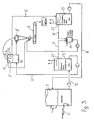
- Fig. 2 shows in more detail the tank 7 for foam removal after the separating point in the separator 5 in the recovery line.
- a prefilter 8 before the separator 5, from which filter the gypsum slurry is directed to the pressure chamber 16 and from there along the input pipe 5a to the separator.
- the separator the gypsum that is solid matter in water separates in a known manner as heavier and it falls into a reject funnel, which is in the beginning of the gypsum conveying line.
- fluid is directed along the excess pipe 5b to the tank 7, which can be open or closed on top.
- foam can, when desired, be kept off from gypsum, if desired, and be handled separately.
- the fluid from which foam is separated is directed to the outlet 12 of the tank below the level of the fluid surface, via which outlet the washing fluid enters the recovery line E and the gas scrubber 1.
- FIG. 2 shows baffle plates, which are placed in the tank 7 in such a manner that they extend vertically.
- the baffle plates are used to control the fluid surface and to prevent the foam separated onto the fluid surface from being carried with the fluid flow to the water outlet 12.
- the first baffle plate 9 extends from the bottom of the tank to a level, which determines the level of the fluid surface in the tank, and it separates the outlet 12 from the rest of the tank and from the fluid inlet.
- baffle plate 10 on the overflow 11 side of the first baffle plate 9, between whose lower end and the tank bottom there is a space for water to flow toward the first baffle plate 9 and the outlet 12.
- the underedge of the second baffle plate 10 is below the upper edge of the first baffle plate 9 and the upper edge extends so high that it is above the fluid surface and the foam layer, and thus maintains the foam on the other side from the first baffle plate 9.
- the baffle plates 9 and 10 thus force the water to flow down and up on a sinuous path before the outlet 12.
- the first baffle plate 9 is attached to the tank, its upper edge is at the same time placed on such a height that by means of it, it is possible to control the fluid level at the correct level position in view of the overflow 11.
- the purpose is to get the fluid level a bit higher than the overflow 11 in order for the foam to be removed from the tank via the overflow on top of the outflowing water.
- a new part is also the overflow pipe 11 a after the overflow, by means of which the foam can be directed to the desired place for further processing.
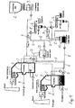
- Fig. 3 shows a chart according to the second alternative, wherein there are several foam removal points in the process fluid flow.
- Gypsum slurry is pumped from the bottom of the scrubber 1 as a continuous flow to the gypsum slurry recycle tank 13, where the fluid settles for the first time. Already at this point, most of the bubbles and the fluid form foam.
- there is a mixer in the gypsum slurry recycle tank the purpose of which is to prevent the gypsum slurry from remaining in the bottom. From the surface of the recycle tank 13 foam can be directed by means of special air or water sprays via the overflow 21 and the foam removal line F to the foam slaking and pumping tank 14.
- the recycle tank 13 thus functions in the washing fluid recycle line as the first tank, from which foam can be removed. Foam removal takes place in this tank advantageously periodically.
- the recycle tank 13 is relatively large in its volume, and by adjusting the ratio of the input and output gypsum slurry flow, its fluid level can be raised, if necessary, close to the overflow 21, via which foam can be removed possibly by means of the above-mentioned sprays.
- a corresponding foam separation can also exist in the circulation water tank 15, to which the substantially foam-free fluid from the above-described tank 7 used in connection with the separator 5 is directed via the recovery line E. Also from this circulation water tank 15, the foam is directed to the foam slaking and pumping tank 14.
- the foam in the foam slaking and pumping tank 14 the foam can be slaked with a water spray and possibly a small amount of a surface tension reducing agent can be added, in which case the particles in the foam, for example soot particles, mix better in the fluid formed from the foam.
- the foam in the tank 7 after the separator 5 is directed along with the gypsum, and in this case also the fluid from the foam slaking and pumping tank 14 can be directed in the same ways along with the gypsum, but it is also possible to process the foam separately.
- Figure 4 shows a process chart, whose material flows correspond to those presented in Fig. 1 .
- the difference here is that there are two flue gas scrubbers 1 in the plant, from both of which the gypsum slurry is gathered to the same recycle tank 13, from which it is directed to two different separators 5, in connection with both of which there can be the above-described tank 7 for foam removal.
- the gypsum slurry recycle tank 13 the in connection with Fig. 3 described foam removal by means of air or water sprays can also exist.
- both scrubbers have a shared gypsum slurry recycle tank 13 and a shared separator 5, in connection with which there is the tank 7 according to Fig. 2 for foam removal.
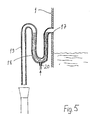
- Fig. 5 shows an overflow pipe arranged in connection with the gas scrubber 1, wherein there is a water seal 18, which prevents the break up of the internal gas pressure.
- the purpose of the overflow pipe is to remove the extra fluid from the scrubber when the surface of the fluid in its lower part has risen too high, for example in disturbance situations.
- fluid or washing fluid used above refers more generally to water or a corresponding washing water, but the invention is applicable to be used in an analogous manner also in such systems, wherein the medium carrying different solids or dissolved components is some other fluid than water.
Landscapes
- Engineering & Computer Science (AREA)
- Chemical & Material Sciences (AREA)
- Health & Medical Sciences (AREA)
- Biomedical Technology (AREA)
- Environmental & Geological Engineering (AREA)
- Analytical Chemistry (AREA)
- General Chemical & Material Sciences (AREA)
- Oil, Petroleum & Natural Gas (AREA)
- Chemical Kinetics & Catalysis (AREA)
- Treating Waste Gases (AREA)
Abstract
Description
- A method and an apparatus for processing flue gas scrubber material flows
- The invention relates to a method for processing flue gas scrubber material flows according to the preamble of
claim 1. The invention relates to an apparatus for processing flue gas scrubber material flows according to the preamble of claim 9. - In power plants, flue gases derived from fuel contain impurities, which are often oxides of sulphur (SOx) because of the sulphur compounds contained in the fuel. These flue gases are cleaned with a gas scrubber, i.e. an absorber, wherein the sulphur dioxide is removed with the washing fluid by using an absorbent in the washing fluid, which absorbent reacts with sulphur dioxide. Limestone-based scrubbers are based on that the sulphur oxides coming with the flue gases react with calcium carbonate and form calcium sulphite, which oxidizes to calcium sulphate (gypsum) under the influence of the oxygen contained in the flue gases and forced oxidation. After this the gypsum can be separated from the fluid and the fluid can be recycled back to the scrubber.
- Limestone scrubbers are advantageous to use because of their low operating costs (cheap absorbent). However, problems have been caused by the detection of foaming and cumulation of the foam in the limestone scrubber in diesel power plants and in other power plants. With the flue gases in a diesel power plant come lubricants and soot, which together with the bubbles of the oxidation air easily form foam onto the fluid surface of the scrubber. Also, the quality of the water used in the washing fluid has an effect on foaming. Because of the recycling of the washing fluid, foam also continuously circulates back to the scrubber, because it does not exit via the hydrocyclone, which is used in separating gypsum from the washing fluid. Because of this, the amount of foam on the fluid surface of the scrubber increases.
- In power industry, it is possible to use a conventional solution for the problem of foaming: the use of anti-foam agent. However, anti-foam agents cause the problem that they may disturb scrubbing process. In addition, their dosage must be continuous and they increase the operating costs of the scrubber. On the other hand, the removal of foam from the scrubber by adjusting the running sequence is difficult because of the floatability of the foam.
- It is an aim of the invention to eliminate the above-mentioned draw-backs and to control foaming without specific anti-foam chemicals. To attain this purpose, the method according to the invention is presented in the appended
claim 1. The apparatus according to the invention is presented in the appended claim 9. - Foam is removed from the washing fluid after the scrubber in a special tank. This can be performed in a tank located after the separating point in a separator known as such, for example in the excess tank of a hydrocyclone, where the washing fluid separated from the gypsum is directed to. Another possibility is to remove foam in the recycle tank before the separator. In the tank, the foam separates as its own phase onto the surface of the fluid and it can be removed from the fluid circulation with physical methods without chemicals. One way is to remove the foam as overflow via an overflow point on an appropriate level. In addition, it is possible to utilize air or water sprays to remove foam from the fluid surface in the tank.
- In addition, it is possible to arrange anti-flow structures in the tank in order to improve the separation of water and foam. The substantially foam-free fluid coming from the tank can be recycled back as the washing fluid of the flue gas scrubber.
- Thus, the purpose is not to prevent foaming, but to prevent it from cumulating in the desulphuration plant at places where it causes problems by disturbing the process or by taking up space. Foam is removed in a controlled manner after the scrubber in the flow direction of the washing fluid and it is directed to the desired place for further processing.
- In the following, the invention will be described in more detail with reference to the appended drawings, in which
-
Fig. 1 shows a flue gas scrubber and material flows connected to it as a diagrammatic plan, -
Fig. 2 shows an apparatus for separating foam according to the invention in more detail, -
Fig. 3 shows an apparatus according to a second embodiment as a process chart, -
Fig. 4 shows an alternative with several gas scrubbers, and -
Fig. 5 shows an overflow tube used in connection with the scrubber. -
Fig. 1 shows the desulphuration plant for flue gases in a diesel power plant as a general process chart, which plant includes agas scrubber 1, whose operating principle is known, to which the flue gases created in fuel combustion are directed from the diesel motors (arrow A) and from which the cleaned flue gases are directed away via a waste flue (arrow B). Here thegas scrubber 1 refers to an actual scrubber tower, where flue gases and washing fluid are put into contact with each other and in whose lower part the washing fluid accumulates.Gas scrubber 1 is a limestone-based scrubber. Fromlimestone silo 2, limestone is supplied in a powdered form to thelimestone slurry tank 3, from where it is pumped into thescrubber 1. Limestone slurry is recycled from the lower part of thescrubber 1 tonozzles 4, which are located above the inlet of flue gases and which form a spray zone, which scrubs the flue gases with a countercurrent principle. Calcium carbonate reacts with the sulphur compounds of flue gases by forming calcium sulphite, which oxidizes into calcium sulphate i.e. gypsum because of the oxygen coming in with flue gases and the forced oxidation taking place in the lower part of the scrubber. Oxidation air is supplied to the fluid volume in the lower part of the scrubber via line C. There is also a mixer in the lower part of the scrubber, the purpose of which is to mix oxidation air to the fluid volume. Gypsum slurry is formed on the bottom of thegas scrubber 1, which slurry is directed from the bottom of the scrubber via the waste line D to theseparator 5. The separator is a hydrocyclone, whose substantially gypsum-free excess is directed back to thescrubber 1 via the recovery line E as washing fluid. Water is used as the carrier of the washing fluid, which water carries the materials used in the flue gas scrubbing process and formed in it. The waste line D and the recovery line E form a recycle line, the purpose of which is to create a water circulation as closed as possible in order to keep the need for fresh water as small as possible. The reject of the hydrocyclone, which is gypsum slurry, which has a high solid matter content, is directed to thebelt filter 6, where water is further removed from the gypsum by filtering and from on top of which the gypsum cake is moved to further processing. The washing fluid received as filtrate from the belt filter can be further recycled to thescrubber 1. - The parts described above and their operations are known as such. Soot foam, which includes air, water and other materials that have come in with flue gases, is formed in the fluid in the lower part of the scrubber, especially due to the combined influence of oxidation air input, soot particles contained by the flue gases, lubricant solids and heavy mixing. In order to remove foam and to prevent foam cumulation, there is a
tank 7 in the plant, wherein the foam that has separated as its own phase on the fluid surface can be separated from the fluid purely in a mechanical manner, and it is not necessary to use anti-foam agents to prevent foam cumulation. The tank is located in the recycling line of washing fluid after the separating point ofseparator 5 in the flow direction of the washing fluid. Thetank 7 is an excess tank normally used in connection with a hydrocyclone, to which the excess of hydrocyclone is directed. Changes have been made in the excess tank in order to separate foam, which will be described hereinbelow. - With the arrangement in question it is possible to prevent the so-called soot foam accumulation in the process fluid of the desulphuration plant, especially in power plants based on diesel motors. The foam removed from the fluid can be directed among the gypsum separated in the
separator 5 or it can be taken out as a separate material flow and be processed separately. The alternatives depend on, e.g., the desired purity of the gypsum produced by the plant and its purpose of use. -
Fig. 2 shows in more detail thetank 7 for foam removal after the separating point in theseparator 5 in the recovery line. In the case shown in the figure, there is in the direction of flow of the gypsum slurry first aprefilter 8 before theseparator 5, from which filter the gypsum slurry is directed to thepressure chamber 16 and from there along the input pipe 5a to the separator. In the separator, the gypsum that is solid matter in water separates in a known manner as heavier and it falls into a reject funnel, which is in the beginning of the gypsum conveying line. From the separator, fluid is directed along the excess pipe 5b to thetank 7, which can be open or closed on top. The tank infig. 2 is the excess tank of a hydrocyclone, which is located on top of thepressure chamber 16.Tank 7 and thepressure chamber 16 below it are in the same container separated by an intermediate floor. The fluid coming from theseparator 5 via the excess pipe 5b ends up below the fluid surface oftank 7. There is still a baffle at the end of the excess pipe 5b, which directs the fluid coming from the pipe upwards in order to separate foam well from it. Foam remains on top of the fluid surface of the tank and it can be removed as overflow and directed to the same gypsum conveyance line as the gypsum separated in the separator. In the figure foam is shown to be directed to the same reject funnel with the gypsum. However, foam can, when desired, be kept off from gypsum, if desired, and be handled separately. The fluid from which foam is separated is directed to theoutlet 12 of the tank below the level of the fluid surface, via which outlet the washing fluid enters the recovery line E and thegas scrubber 1. - In connection with the hydrocyclone, it has been known to use an excess tank, to which the excess can be directed from the separating point of fluid and gypsum. In the following, the modifications to the structure of this type of an excess tank in order to use it for foam removal will be discussed.
Fig. 2 shows baffle plates, which are placed in thetank 7 in such a manner that they extend vertically. The baffle plates are used to control the fluid surface and to prevent the foam separated onto the fluid surface from being carried with the fluid flow to thewater outlet 12. The first baffle plate 9 extends from the bottom of the tank to a level, which determines the level of the fluid surface in the tank, and it separates theoutlet 12 from the rest of the tank and from the fluid inlet. There is asecond baffle plate 10 on theoverflow 11 side of the first baffle plate 9, between whose lower end and the tank bottom there is a space for water to flow toward the first baffle plate 9 and theoutlet 12. The underedge of thesecond baffle plate 10 is below the upper edge of the first baffle plate 9 and the upper edge extends so high that it is above the fluid surface and the foam layer, and thus maintains the foam on the other side from the first baffle plate 9. Thebaffle plates 9 and 10 thus force the water to flow down and up on a sinuous path before theoutlet 12. When the first baffle plate 9 is attached to the tank, its upper edge is at the same time placed on such a height that by means of it, it is possible to control the fluid level at the correct level position in view of theoverflow 11. The purpose is to get the fluid level a bit higher than theoverflow 11 in order for the foam to be removed from the tank via the overflow on top of the outflowing water. A new part is also theoverflow pipe 11 a after the overflow, by means of which the foam can be directed to the desired place for further processing. -
Fig. 3 shows a chart according to the second alternative, wherein there are several foam removal points in the process fluid flow. Gypsum slurry is pumped from the bottom of thescrubber 1 as a continuous flow to the gypsumslurry recycle tank 13, where the fluid settles for the first time. Already at this point, most of the bubbles and the fluid form foam. In addition, there is a mixer in the gypsum slurry recycle tank, the purpose of which is to prevent the gypsum slurry from remaining in the bottom. From the surface of therecycle tank 13 foam can be directed by means of special air or water sprays via theoverflow 21 and the foam removal line F to the foam slaking andpumping tank 14. Therecycle tank 13 thus functions in the washing fluid recycle line as the first tank, from which foam can be removed. Foam removal takes place in this tank advantageously periodically. Therecycle tank 13 is relatively large in its volume, and by adjusting the ratio of the input and output gypsum slurry flow, its fluid level can be raised, if necessary, close to theoverflow 21, via which foam can be removed possibly by means of the above-mentioned sprays. In addition, a corresponding foam separation can also exist in thecirculation water tank 15, to which the substantially foam-free fluid from the above-describedtank 7 used in connection with theseparator 5 is directed via the recovery line E. Also from thiscirculation water tank 15, the foam is directed to the foam slaking andpumping tank 14. In the foam slaking andpumping tank 14 the foam can be slaked with a water spray and possibly a small amount of a surface tension reducing agent can be added, in which case the particles in the foam, for example soot particles, mix better in the fluid formed from the foam. As can be seen in the figure, the foam in thetank 7 after theseparator 5 is directed along with the gypsum, and in this case also the fluid from the foam slaking andpumping tank 14 can be directed in the same ways along with the gypsum, but it is also possible to process the foam separately. -
Figure 4 shows a process chart, whose material flows correspond to those presented inFig. 1 . The difference here is that there are twoflue gas scrubbers 1 in the plant, from both of which the gypsum slurry is gathered to thesame recycle tank 13, from which it is directed to twodifferent separators 5, in connection with both of which there can be the above-describedtank 7 for foam removal. In the gypsumslurry recycle tank 13, the in connection withFig. 3 described foam removal by means of air or water sprays can also exist. Also, it is possible that both scrubbers have a shared gypsumslurry recycle tank 13 and a sharedseparator 5, in connection with which there is thetank 7 according toFig. 2 for foam removal. -
Fig. 5 shows an overflow pipe arranged in connection with thegas scrubber 1, wherein there is awater seal 18, which prevents the break up of the internal gas pressure. The purpose of the overflow pipe is to remove the extra fluid from the scrubber when the surface of the fluid in its lower part has risen too high, for example in disturbance situations. It has been known in gas scrubbers to use an overflow pipe taken through the chamber wall, in which pipe there is an internal water seal, as which is functioning a pipe extending below the scrubber fluid surface. The internal water seal is in the solution ofFig. 1 been replaced with anexternal water seal 18 in such a manner that it is located outside thescrubber 1 chamber below theoverflow point 17 as an U-shaped pipe, whose upright branch located the furthest from the overflow point extends above theoverflow point 17. After this, there is adrain pipe 19, through which the extra fluid can flow out by means of gravity. A water connection 20 has been brought to the lower part of thewater seal 18, through which water is continuously supplied in a small flow, the purpose of which is to maintain the fluid surface of thewater seal 18 at the level of theoverflow point 17 with a small overflow into the scrubber via theoverflow point 17. Theoverflow point 17 opens inside the scrubber above the fluid level. In this manner it is possible to avoid foam accumulation in the water seal and its continuous gushing out from the scrubber via the overflow pipe, which has been a problem in those scrubbers, where the water seal is inside the scrubber as a pipe extending below the fluid level, which pipe is easily filled with foam. Thus it is possible to prevent the uncontrolled output of foam from the scrubber and to gather foam from the washing fluid flow directed outside thescrubber 1 via one or more tanks. - Even though the foam problems of flue gas washing fluids in diesel power plants have been discussed above, it can be used in all power plants using flue gas scrubbing processes with calcium-based absorbent, which processes have foaming problems because of the aeration required by forced oxidation. The term fluid or washing fluid used above refers more generally to water or a corresponding washing water, but the invention is applicable to be used in an analogous manner also in such systems, wherein the medium carrying different solids or dissolved components is some other fluid than water.
Claims (18)
- A method for processing flue gas scrubber material flows, in which method flue gas is scrubbed in a flue gas scrubber (1) with a washing fluid containing calcium-based absorbent to absorb sulphur oxides from the flue gases and the formed gypsum slurry is directed from the flue gas scrubber (1) to a separator (5), in whose separation point the gypsum is separated from the washing fluid, and from which the gypsum and gypsum-free washing fluid are taken out as separate material flows, characterized in that from the separator (5) the gypsum-free washing fluid is directed to a tank (7), in which tank foam is separated from the gypsum-free washing fluid and taken out from the tank (7).
- The method according to claim 1, characterized in that from the flue gas scrubber (1) the gypsum slurry is directed to a tank (13) located before the separating point of the separator (5), in which tank (13) foam is separated from the gypsum slurry and taken out from the tank (13).
- The method according to claim 1 or 2, characterized in that the foam is taken out from the surface of the tank (7, 13).
- The method according to claim 3, characterized in that the foam is taken out as overflow.
- The method according to claim 3 or 4, characterized in that in the tank (7) the washing fluid is directed away from the foam towards its own outlet by means of vertically extending baffle structures, which prevent the direct horizontal flow of water.
- The method according to any of the preceding claims, characterized in that the washing fluid is recycled from the tank (7, 13) back to the flue gas scrubber (1).
- The method according to claim 6, characterized in that the washing fluid is directed from the tank (7, 13) back to the flue gas scrubber (1) via at least one new foam removal phase.
- The method according to any of the preceding claims, characterized in that gypsum is separated from the washing fluid with a hydrocyclone, whose excess is directed to the tank (7), wherein foam is separated from the fluid.
- An apparatus for processing flue gas scrubber material flows, in which apparatus there is a flue gas scrubber (1) using a calcium-based absorbent, an outlet line (D) for directing the gypsum-containing washing fluid out of the scrubber to a separator (5), as well as the separator (5) having a separation point for separating the gypsum and the gypsum-free washing fluid, characterized in that in the direction of flow of the washing fluid there is a tank (7) after the separation point of the separator (5), in which there are means for separating foam from the upper part of the tank and an outlet (12) or an outlet point for removing clean washing fluid from foam.
- The apparatus according to claim 9, characterized in that in the direction of flow of the washing fluid there is a tank (13) before the separation point of the separator (5), in which there are means for separating foam from the upper part of the tank and an outlet (21) or an outlet point for removing cleaned gypsum-containing washing fluid from foam.
- The apparatus according to claim 9 or 10, characterized in that the means for separating foam comprise an overflow (11, 21) for directing the foam on the fluid surface of the tank (7, 13) away.
- The apparatus according to claim 11, characterized in that in the tank (7) there is one or more vertically extending baffle structures between the overflow (11) and the outlet (12) or the outlet point, such as a baffle plate (9, 10) or the like.
- The apparatus according to claim 12, characterized in that the baffle structure (9) is located between said overflow (11) and tank outlet (12) or outlet point, and is directed from the bottom of the tank (7) upwards.
- The apparatus according to claim 13, characterized in that the second baffle structure (10) is located between the first baffle structure (9) and the overflow (11), extends above the first baffle structure (9), and extends at the lower end to a distance from the bottom of the tank (7), thus leaving a flow outlet free for the fluid to flow towards the tank outlet (12) or the outlet point.
- The apparatus according to claim 10, characterized in that the means for foam removal in the tank (13) before the separating point of the separator (5) comprise a spray device or the like for directing the foam away from the tank (13) fluid surface.
- The apparatus according to any of the preceding claims 9 to 15, characterized in that after the tank (7) following the separating point of the separator (5) there is another tank (15) having means for directing foam away from the upper part of the tank and an outlet for removing clean washing fluid from foam.
- The apparatus according to any of the preceding claims 9 to 16, characterized in that an overflow pipe, whose water seal (18) is located outside the scrubber below the overflow point (17), has been connected to the scrubber (1).
- The apparatus according to claim 17, characterized in that in the water seal (18) there is a water connection (20), through which water can be supplied to the water seal.
Applications Claiming Priority (3)
| Application Number | Priority Date | Filing Date | Title |
|---|---|---|---|
| FI20021704 | 2002-09-24 | ||
| FI20021704A FI113843B (en) | 2002-09-24 | 2002-09-24 | Method and plant for processing material flows of a flue gas scrubber |
| PCT/FI2003/000676 WO2004028666A1 (en) | 2002-09-24 | 2003-09-17 | A method and an apparatus for processing flue gas scrubber material flows |
Publications (2)
| Publication Number | Publication Date |
|---|---|
| EP1542785A1 EP1542785A1 (en) | 2005-06-22 |
| EP1542785B1 true EP1542785B1 (en) | 2011-07-06 |
Family
ID=8564639
Family Applications (1)
| Application Number | Title | Priority Date | Filing Date |
|---|---|---|---|
| EP20030798201 Expired - Lifetime EP1542785B1 (en) | 2002-09-24 | 2003-09-17 | A method and an apparatus for processing flue gas scrubber material flows |
Country Status (6)
| Country | Link |
|---|---|
| US (1) | US7306776B2 (en) |
| EP (1) | EP1542785B1 (en) |
| AT (1) | ATE515318T1 (en) |
| AU (1) | AU2003262601A1 (en) |
| FI (1) | FI113843B (en) |
| WO (1) | WO2004028666A1 (en) |
Families Citing this family (11)
| Publication number | Priority date | Publication date | Assignee | Title |
|---|---|---|---|---|
| JP5384799B2 (en) * | 2007-03-30 | 2014-01-08 | 三菱重工メカトロシステムズ株式会社 | Exhaust gas treatment apparatus and exhaust gas treatment method |
| DE102007050904B4 (en) * | 2007-10-23 | 2013-07-25 | Babcock Noell Gmbh | Plant and process for the purification of flue gases |
| JP5031003B2 (en) * | 2009-07-17 | 2012-09-19 | 三菱重工業株式会社 | Exhaust gas treatment equipment |
| CN105561770A (en) * | 2015-03-17 | 2016-05-11 | 孙厚杰 | Wet flue gas desulfurization absorption tower |
| EP3069781B1 (en) * | 2015-03-20 | 2019-05-08 | General Electric Technology GmbH | System for sulphur removal from a flue gas |
| CA2940950C (en) * | 2015-09-03 | 2024-01-09 | Questor Technology Inc. | Method and system for reducing produced water disposal volumes utilizing waste heat |
| JP7242378B2 (en) * | 2019-03-28 | 2023-03-20 | 三菱重工業株式会社 | Separation and recovery system and separation and recovery method |
| CN110317642B (en) * | 2019-07-05 | 2021-05-25 | 宁波科新化工工程技术有限公司 | Extraction process of desulfurization regenerated sulfur foam |
| JP2021154245A (en) * | 2020-03-27 | 2021-10-07 | 三菱パワー株式会社 | Absorption liquid treatment system for flue gas desulfurization equipment |
| CN111701436B (en) * | 2020-06-23 | 2022-10-04 | 湖北真诚纸业有限公司 | Double-alkali desulfurization method |
| CN113877402B (en) * | 2021-11-02 | 2023-07-14 | 福建龙净环保股份有限公司 | Wet desulfurization process system and wet desulfurization process method with ultralow wastewater discharge capacity |
Family Cites Families (5)
| Publication number | Priority date | Publication date | Assignee | Title |
|---|---|---|---|---|
| DE3331993A1 (en) * | 1983-09-05 | 1984-03-29 | Heinz Prof. Dr.-Ing. 7261 Gechingen Blenke | Process and equipment for degassing gas/liquid systems without foam formation |
| WO1987005530A1 (en) | 1986-03-19 | 1987-09-24 | Insinööritoimisto Lisop Oy | Flue-gas purifying procedure |
| JP3564289B2 (en) | 1997-02-05 | 2004-09-08 | 三菱重工業株式会社 | Method and apparatus for treating desulfurization absorbent |
| JP3422738B2 (en) * | 2000-01-14 | 2003-06-30 | 三菱重工業株式会社 | Exhaust gas desulfurization method and system |
| US6939523B2 (en) * | 2002-12-10 | 2005-09-06 | Chemical Lime Company | Method of removing SO3 from flue gases |
-
2002
- 2002-09-24 FI FI20021704A patent/FI113843B/en not_active IP Right Cessation
-
2003
- 2003-09-17 WO PCT/FI2003/000676 patent/WO2004028666A1/en not_active Ceased
- 2003-09-17 AT AT03798201T patent/ATE515318T1/en not_active IP Right Cessation
- 2003-09-17 US US10/528,407 patent/US7306776B2/en not_active Expired - Lifetime
- 2003-09-17 AU AU2003262601A patent/AU2003262601A1/en not_active Abandoned
- 2003-09-17 EP EP20030798201 patent/EP1542785B1/en not_active Expired - Lifetime
Also Published As
| Publication number | Publication date |
|---|---|
| EP1542785A1 (en) | 2005-06-22 |
| WO2004028666A1 (en) | 2004-04-08 |
| AU2003262601A1 (en) | 2004-04-19 |
| ATE515318T1 (en) | 2011-07-15 |
| FI113843B (en) | 2004-06-30 |
| US7306776B2 (en) | 2007-12-11 |
| FI20021704L (en) | 2004-03-25 |
| FI20021704A0 (en) | 2002-09-24 |
| US20050271569A1 (en) | 2005-12-08 |
Similar Documents
| Publication | Publication Date | Title |
|---|---|---|
| US6214097B1 (en) | Flue gas scrubbing apparatus | |
| US4526764A (en) | Scrubber operating method for the desulfurization of flue gases | |
| CN101939080B (en) | Installation and method for cleaning flue gases | |
| US5645802A (en) | Method and apparatus for the treatment of a waste gas containing dists and chemical contaminants | |
| KR100890854B1 (en) | Method and apparatus for separating sulfur dioxide from gas | |
| WO2005007274A1 (en) | A method and a device for the separation of sulphur dioxide from a gas | |
| US7306776B2 (en) | Method and an apparatus for processing flue gas scrubber material flows | |
| RU2149679C1 (en) | Method of scrubbing and device for removal of sulfur oxides from combustion products | |
| CN1196001A (en) | Method and device for wet separation of acid gas | |
| EP0706814B1 (en) | Wet flue-gas desulphurization system | |
| US6090357A (en) | Flue gas scrubbing method | |
| EA000771B1 (en) | A method and apparatus for removing gaseous elementary mercury from a gas | |
| US6007783A (en) | Flue gas treating system and process | |
| WO2018163733A1 (en) | Desulfurizing method and desulfurizing device | |
| SK92093A3 (en) | Method of desulfurization of flue gases and device for executing this method | |
| MXPA96006215A (en) | Improved method of wet deposition and apparatus to remove sulfur oxides from combust effluents |
Legal Events
| Date | Code | Title | Description |
|---|---|---|---|
| PUAI | Public reference made under article 153(3) epc to a published international application that has entered the european phase |
Free format text: ORIGINAL CODE: 0009012 |
|
| 17P | Request for examination filed |
Effective date: 20050322 |
|
| AK | Designated contracting states |
Kind code of ref document: A1 Designated state(s): AT BE BG CH CY CZ DE DK EE ES FI FR GB GR HU IE IT LI LU MC NL PT RO SE SI SK TR |
|
| AX | Request for extension of the european patent |
Extension state: AL LT LV MK |
|
| DAX | Request for extension of the european patent (deleted) | ||
| 17Q | First examination report despatched |
Effective date: 20071228 |
|
| RAP1 | Party data changed (applicant data changed or rights of an application transferred) |
Owner name: METSO POWER OY |
|
| GRAP | Despatch of communication of intention to grant a patent |
Free format text: ORIGINAL CODE: EPIDOSNIGR1 |
|
| GRAS | Grant fee paid |
Free format text: ORIGINAL CODE: EPIDOSNIGR3 |
|
| GRAA | (expected) grant |
Free format text: ORIGINAL CODE: 0009210 |
|
| AK | Designated contracting states |
Kind code of ref document: B1 Designated state(s): AT BE BG CH CY CZ DE DK EE ES FI FR GB GR HU IE IT LI LU MC NL PT RO SE SI SK TR |
|
| REG | Reference to a national code |
Ref country code: GB Ref legal event code: FG4D |
|
| REG | Reference to a national code |
Ref country code: CH Ref legal event code: EP |
|
| REG | Reference to a national code |
Ref country code: IE Ref legal event code: FG4D |
|
| REG | Reference to a national code |
Ref country code: DE Ref legal event code: R096 Ref document number: 60337640 Country of ref document: DE Effective date: 20110901 |
|
| REG | Reference to a national code |
Ref country code: NL Ref legal event code: VDEP Effective date: 20110706 |
|
| REG | Reference to a national code |
Ref country code: GR Ref legal event code: EP Ref document number: 20110402258 Country of ref document: GR Effective date: 20111013 |
|
| PG25 | Lapsed in a contracting state [announced via postgrant information from national office to epo] |
Ref country code: SI Free format text: LAPSE BECAUSE OF FAILURE TO SUBMIT A TRANSLATION OF THE DESCRIPTION OR TO PAY THE FEE WITHIN THE PRESCRIBED TIME-LIMIT Effective date: 20110706 |
|
| REG | Reference to a national code |
Ref country code: AT Ref legal event code: MK05 Ref document number: 515318 Country of ref document: AT Kind code of ref document: T Effective date: 20110706 |
|
| PG25 | Lapsed in a contracting state [announced via postgrant information from national office to epo] |
Ref country code: BE Free format text: LAPSE BECAUSE OF FAILURE TO SUBMIT A TRANSLATION OF THE DESCRIPTION OR TO PAY THE FEE WITHIN THE PRESCRIBED TIME-LIMIT Effective date: 20110706 Ref country code: FI Free format text: LAPSE BECAUSE OF FAILURE TO SUBMIT A TRANSLATION OF THE DESCRIPTION OR TO PAY THE FEE WITHIN THE PRESCRIBED TIME-LIMIT Effective date: 20110706 Ref country code: SE Free format text: LAPSE BECAUSE OF FAILURE TO SUBMIT A TRANSLATION OF THE DESCRIPTION OR TO PAY THE FEE WITHIN THE PRESCRIBED TIME-LIMIT Effective date: 20110706 Ref country code: PT Free format text: LAPSE BECAUSE OF FAILURE TO SUBMIT A TRANSLATION OF THE DESCRIPTION OR TO PAY THE FEE WITHIN THE PRESCRIBED TIME-LIMIT Effective date: 20111107 Ref country code: NL Free format text: LAPSE BECAUSE OF FAILURE TO SUBMIT A TRANSLATION OF THE DESCRIPTION OR TO PAY THE FEE WITHIN THE PRESCRIBED TIME-LIMIT Effective date: 20110706 |
|
| PG25 | Lapsed in a contracting state [announced via postgrant information from national office to epo] |
Ref country code: CY Free format text: LAPSE BECAUSE OF FAILURE TO SUBMIT A TRANSLATION OF THE DESCRIPTION OR TO PAY THE FEE WITHIN THE PRESCRIBED TIME-LIMIT Effective date: 20110706 Ref country code: AT Free format text: LAPSE BECAUSE OF FAILURE TO SUBMIT A TRANSLATION OF THE DESCRIPTION OR TO PAY THE FEE WITHIN THE PRESCRIBED TIME-LIMIT Effective date: 20110706 |
|
| PG25 | Lapsed in a contracting state [announced via postgrant information from national office to epo] |
Ref country code: CZ Free format text: LAPSE BECAUSE OF FAILURE TO SUBMIT A TRANSLATION OF THE DESCRIPTION OR TO PAY THE FEE WITHIN THE PRESCRIBED TIME-LIMIT Effective date: 20110706 Ref country code: MC Free format text: LAPSE BECAUSE OF NON-PAYMENT OF DUE FEES Effective date: 20110930 Ref country code: SK Free format text: LAPSE BECAUSE OF FAILURE TO SUBMIT A TRANSLATION OF THE DESCRIPTION OR TO PAY THE FEE WITHIN THE PRESCRIBED TIME-LIMIT Effective date: 20110706 |
|
| REG | Reference to a national code |
Ref country code: CH Ref legal event code: PL |
|
| PLBE | No opposition filed within time limit |
Free format text: ORIGINAL CODE: 0009261 |
|
| STAA | Information on the status of an ep patent application or granted ep patent |
Free format text: STATUS: NO OPPOSITION FILED WITHIN TIME LIMIT |
|
| PG25 | Lapsed in a contracting state [announced via postgrant information from national office to epo] |
Ref country code: RO Free format text: LAPSE BECAUSE OF FAILURE TO SUBMIT A TRANSLATION OF THE DESCRIPTION OR TO PAY THE FEE WITHIN THE PRESCRIBED TIME-LIMIT Effective date: 20110706 Ref country code: EE Free format text: LAPSE BECAUSE OF FAILURE TO SUBMIT A TRANSLATION OF THE DESCRIPTION OR TO PAY THE FEE WITHIN THE PRESCRIBED TIME-LIMIT Effective date: 20110706 |
|
| 26N | No opposition filed |
Effective date: 20120411 |
|
| REG | Reference to a national code |
Ref country code: IE Ref legal event code: MM4A |
|
| REG | Reference to a national code |
Ref country code: FR Ref legal event code: ST Effective date: 20120531 |
|
| GBPC | Gb: european patent ceased through non-payment of renewal fee |
Effective date: 20111006 |
|
| PG25 | Lapsed in a contracting state [announced via postgrant information from national office to epo] |
Ref country code: DK Free format text: LAPSE BECAUSE OF FAILURE TO SUBMIT A TRANSLATION OF THE DESCRIPTION OR TO PAY THE FEE WITHIN THE PRESCRIBED TIME-LIMIT Effective date: 20110706 |
|
| PG25 | Lapsed in a contracting state [announced via postgrant information from national office to epo] |
Ref country code: LI Free format text: LAPSE BECAUSE OF NON-PAYMENT OF DUE FEES Effective date: 20110930 Ref country code: CH Free format text: LAPSE BECAUSE OF NON-PAYMENT OF DUE FEES Effective date: 20110930 Ref country code: IE Free format text: LAPSE BECAUSE OF NON-PAYMENT OF DUE FEES Effective date: 20110917 |
|
| REG | Reference to a national code |
Ref country code: DE Ref legal event code: R097 Ref document number: 60337640 Country of ref document: DE Effective date: 20120411 |
|
| PG25 | Lapsed in a contracting state [announced via postgrant information from national office to epo] |
Ref country code: GB Free format text: LAPSE BECAUSE OF NON-PAYMENT OF DUE FEES Effective date: 20111006 Ref country code: FR Free format text: LAPSE BECAUSE OF NON-PAYMENT OF DUE FEES Effective date: 20110930 |
|
| PG25 | Lapsed in a contracting state [announced via postgrant information from national office to epo] |
Ref country code: ES Free format text: LAPSE BECAUSE OF FAILURE TO SUBMIT A TRANSLATION OF THE DESCRIPTION OR TO PAY THE FEE WITHIN THE PRESCRIBED TIME-LIMIT Effective date: 20111017 |
|
| PG25 | Lapsed in a contracting state [announced via postgrant information from national office to epo] |
Ref country code: LU Free format text: LAPSE BECAUSE OF NON-PAYMENT OF DUE FEES Effective date: 20110917 |
|
| PG25 | Lapsed in a contracting state [announced via postgrant information from national office to epo] |
Ref country code: BG Free format text: LAPSE BECAUSE OF FAILURE TO SUBMIT A TRANSLATION OF THE DESCRIPTION OR TO PAY THE FEE WITHIN THE PRESCRIBED TIME-LIMIT Effective date: 20111006 |
|
| PG25 | Lapsed in a contracting state [announced via postgrant information from national office to epo] |
Ref country code: TR Free format text: LAPSE BECAUSE OF FAILURE TO SUBMIT A TRANSLATION OF THE DESCRIPTION OR TO PAY THE FEE WITHIN THE PRESCRIBED TIME-LIMIT Effective date: 20110706 |
|
| PG25 | Lapsed in a contracting state [announced via postgrant information from national office to epo] |
Ref country code: HU Free format text: LAPSE BECAUSE OF FAILURE TO SUBMIT A TRANSLATION OF THE DESCRIPTION OR TO PAY THE FEE WITHIN THE PRESCRIBED TIME-LIMIT Effective date: 20110706 |
|
| PGFP | Annual fee paid to national office [announced via postgrant information from national office to epo] |
Ref country code: DE Payment date: 20200925 Year of fee payment: 18 Ref country code: GR Payment date: 20200918 Year of fee payment: 18 |
|
| PGFP | Annual fee paid to national office [announced via postgrant information from national office to epo] |
Ref country code: IT Payment date: 20200922 Year of fee payment: 18 |
|
| REG | Reference to a national code |
Ref country code: DE Ref legal event code: R119 Ref document number: 60337640 Country of ref document: DE |
|
| PG25 | Lapsed in a contracting state [announced via postgrant information from national office to epo] |
Ref country code: DE Free format text: LAPSE BECAUSE OF NON-PAYMENT OF DUE FEES Effective date: 20220401 |
|
| PG25 | Lapsed in a contracting state [announced via postgrant information from national office to epo] |
Ref country code: GR Free format text: LAPSE BECAUSE OF NON-PAYMENT OF DUE FEES Effective date: 20220407 |
|
| PG25 | Lapsed in a contracting state [announced via postgrant information from national office to epo] |
Ref country code: IT Free format text: LAPSE BECAUSE OF NON-PAYMENT OF DUE FEES Effective date: 20210917 |