EP1542446A1 - An image reading device and method, and an image forming apparatus and method - Google Patents
An image reading device and method, and an image forming apparatus and method Download PDFInfo
- Publication number
- EP1542446A1 EP1542446A1 EP04029265A EP04029265A EP1542446A1 EP 1542446 A1 EP1542446 A1 EP 1542446A1 EP 04029265 A EP04029265 A EP 04029265A EP 04029265 A EP04029265 A EP 04029265A EP 1542446 A1 EP1542446 A1 EP 1542446A1
- Authority
- EP
- European Patent Office
- Prior art keywords
- image
- reading
- signal amplifier
- value
- image sensor
- Prior art date
- Legal status (The legal status is an assumption and is not a legal conclusion. Google has not performed a legal analysis and makes no representation as to the accuracy of the status listed.)
- Granted
Links
- 238000000034 method Methods 0.000 title claims description 45
- 230000003321 amplification Effects 0.000 claims abstract description 27
- 238000003199 nucleic acid amplification method Methods 0.000 claims abstract description 27
- 238000000701 chemical imaging Methods 0.000 description 29
- 238000010586 diagram Methods 0.000 description 6
- 230000015572 biosynthetic process Effects 0.000 description 2
- 238000004519 manufacturing process Methods 0.000 description 2
- 230000008569 process Effects 0.000 description 2
- 230000004044 response Effects 0.000 description 2
- 241000227425 Pieris rapae crucivora Species 0.000 description 1
- 230000008859 change Effects 0.000 description 1
- 238000012986 modification Methods 0.000 description 1
- 230000004048 modification Effects 0.000 description 1
- 230000035945 sensitivity Effects 0.000 description 1
Images




Classifications
-
- H—ELECTRICITY
- H04—ELECTRIC COMMUNICATION TECHNIQUE
- H04N—PICTORIAL COMMUNICATION, e.g. TELEVISION
- H04N1/00—Scanning, transmission or reproduction of documents or the like, e.g. facsimile transmission; Details thereof
- H04N1/04—Scanning arrangements, i.e. arrangements for the displacement of active reading or reproducing elements relative to the original or reproducing medium, or vice versa
- H04N1/10—Scanning arrangements, i.e. arrangements for the displacement of active reading or reproducing elements relative to the original or reproducing medium, or vice versa using flat picture-bearing surfaces
- H04N1/1013—Scanning arrangements, i.e. arrangements for the displacement of active reading or reproducing elements relative to the original or reproducing medium, or vice versa using flat picture-bearing surfaces with sub-scanning by translatory movement of at least a part of the main-scanning components
- H04N1/1017—Scanning arrangements, i.e. arrangements for the displacement of active reading or reproducing elements relative to the original or reproducing medium, or vice versa using flat picture-bearing surfaces with sub-scanning by translatory movement of at least a part of the main-scanning components the main-scanning components remaining positionally invariant with respect to one another in the sub-scanning direction
-
- H—ELECTRICITY
- H04—ELECTRIC COMMUNICATION TECHNIQUE
- H04N—PICTORIAL COMMUNICATION, e.g. TELEVISION
- H04N1/00—Scanning, transmission or reproduction of documents or the like, e.g. facsimile transmission; Details thereof
- H04N1/04—Scanning arrangements, i.e. arrangements for the displacement of active reading or reproducing elements relative to the original or reproducing medium, or vice versa
-
- H—ELECTRICITY
- H04—ELECTRIC COMMUNICATION TECHNIQUE
- H04N—PICTORIAL COMMUNICATION, e.g. TELEVISION
- H04N1/00—Scanning, transmission or reproduction of documents or the like, e.g. facsimile transmission; Details thereof
- H04N1/40—Picture signal circuits
- H04N1/407—Control or modification of tonal gradation or of extreme levels, e.g. background level
- H04N1/4076—Control or modification of tonal gradation or of extreme levels, e.g. background level dependent on references outside the picture
-
- H—ELECTRICITY
- H04—ELECTRIC COMMUNICATION TECHNIQUE
- H04N—PICTORIAL COMMUNICATION, e.g. TELEVISION
- H04N2201/00—Indexing scheme relating to scanning, transmission or reproduction of documents or the like, and to details thereof
- H04N2201/04—Scanning arrangements
- H04N2201/0402—Arrangements not specific to a particular one of the scanning methods covered by groups H04N1/04 - H04N1/207
- H04N2201/0426—Scanning an image in a series of contiguous zones
Definitions
- the present invention relates to image reading devices and method, and image forming apparatus and method.
- Prior image forming apparatus compatible with A0 size subject paper uses only one close image sensor (referred to as "CIS" hereinafter). That is, such a prior image forming apparatus uses a CIS having a length of A0 size paper width to read an original subject. However, such prior image forming apparatus is very large and takes high manufacturing cost, resulting in high price of the image forming apparatus.
- the white color reference adjustment is a process wherein an output of the CIS reading light generated by a light source is adjusted (gain adjusted) to a predetermined output reference value by an amplifier (or a signal amplifier) before image forming.
- Patent Reference 1 Japanese Patent Laid-open Publication 2001-157006
- a prior image forming apparatus compatible with A0 size paper having plural CISs arranged zigzag has only one amplifier (or signal amplifier), and therefore can adjust one white reference for only one CIS (e.g. CISm shown in Fig. 2), and the other CISs cannot be adjusted, resulting in variations in CIS outputs.
- each CIS has a different white color reference, and when the same white color is read by plural CISs, some CISs output grey color, providing bad image forming.
- the invention provides as follows.
- an image reading device having plural image sensors and a reading controller for obtaining image data over a subject by joining sub-image data outputs read by the plural image sensors, each image sensor comprising:
- an image forming apparatus including the image reading device as explained above, comprising:
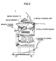
- Fig. 3 generally shows an image forming apparatus to which the present invention may be applied.
- the image forming apparatus 1 comprises an image reader 10, an image writer 11, an image forming unit 12, a manual paper feeder 13, a roll paper feeder 14, and a cassette paper feeder 15.
- the image reader 10 corresponds to an image reading device 50 (explained later), and reads image data and the like.
- the image writer 11 responds to image data read by the image reader 10, and writes the image on a paper fed by the roll paper feeder 14.
- the image forming unit 12 forms an image based on the image data ready by the image reader 10, to write it on a paper fed by the roll paper feeder 14.
- the manual paper feeder 13 is used when a user manually feeds a sheet of paper to the image forming apparatus 1.
- the roll paper feeder 14 supplies a sheet of paper contained in the cassette paper feeder 15 to the image writer 11.
- the cassette paper feeder 15 stores sheets of papers put by the user.
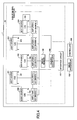
- Fig. 4 is a block diagram of an example of an image forming apparatus 1 according to a first embodiment of the present invention.
- the image forming apparatus 1 shown in Fig. 4 comprises an image reading device 50, an image processor 108, and a controller 109.
- the image reading device 50 comprises plural CISs 100-104 and light sources 200-204.
- the CISs and the light sources are arranged zigzag.
- Each of the CISs has N reading pixels, and each CIS 100-104 has a signal amplifier 1-5, and an A/D converter 1-5.
- the image reading device 50 further comprises an image memory 105, a reading controller 106 and an interface 107.
- the light sources 200-204 emit light in response to a request from the reading controller 106 and others.
- the CISs 100-104 are image sensors that convert light signals (pixels) to electric signals.
- the amplifiers 1-5 amplify electric signals.
- the A/D converters 1-5 convert analog values (signals) output from corresponding CIS 100-104 and amplified by corresponding amplifier 1-5 to digital values (signals).
- the image memory 105 relates to image reading and processing, and stores image data.
- the reading controller 106 performs white reference adjustment processing, which is explained later.
- the interface circuit 107 connects the image reading device 50 to the image forming apparatus 1, or connects the reading controller 106 of the image reading device 50 to an image processor 108 of the image forming apparatus 1.
- a controller 109 controls the image forming apparatus overall.
- the image processor 108 forms an image, based on the reading value of the reference white board adjusted by the reading controller 106 for each CIS.
- the white reference adjustment processing is performed by the reading controller 106 each time whenever the image forming apparatus 1 is first started (powered-on) by the user in the morning, or resumed or woken up from sleeping mode.
- the white reference adjustment process is performed so that the reading controller 106 makes the CISs read a white board 22 shown in Fig. 5.
- the CISs of the image reading device 50 are arranged zigzag as shown in Fig. 1, which does not limit the scope of the present invention.
- FIG. 5 A cross section of the image reading device 50 cut by A-A' plane in Fig. 1 is shown in Fig. 5.
- the cross-sectional view of the image reading device 50 shown in Fig. 5 corresponds to a portion indicated by A in Fig. 3.
- the image reading device 50 includes conveying rollers 21, a reference white board 22 and CIS 1-5.
- the conveying rollers 21 convey an original paper.
- the reference white board 22 is a white board used for white reference adjustment processing.
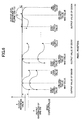
- Fig. 6 shows an example of signal levels of plural CISs, wherein their signal outputs are adjusted (amplification factor adjustment or white reference adjustment) by the reading controller 106.
- the reading controller 106 When the image forming apparatus 1 is powered on by a user, the reading controller 106 turns on only the light source 200 corresponding to the CIS 100, and performs the white reference adjustment for the light from the light source 200.
- This white reference adjustment processing is processing wherein the reading controller 106 adjusts an amplification factor of the amplifier 1 so as to change a peak of a value (or output value) of the white reference 22 read by CIS 100 to a predetermined output value (for example, an output value A as shown in Fig. 6).
- the output value (or analog value) of the CIS after the white reference adjustment processing is converted to a digital value (for example, a digital value of 220 when 8-bit processing is carried out) by an A/D converter.
- the reading controller 106 After the adjustment (white reference adjustment) of the amplification factor of the amplifier 1 corresponding to the CIS 100, the reading controller 106 turns off the light source 200 corresponding to the CIS 100. At that time, since the light sources 201 ⁇ 204 corresponding to other CIS 101-104 are also off, A/D converted output values from the CIS 100-104 are zero or close to zero (digital value equivalent to black).
- the reading controller 106 turns on only the light source 201 corresponding to the CIS 101, and performs the white reference adjustment processing against the amplifier 2 corresponding to the CIS 101.
- the reading controller 106 performs the same processing against the CIS 102-104 (or the amplifiers 3-5 corresponding the CIS 102-104).
- the white reference adjustment is finished for all the CISs (or all the amplifiers).
- the peak value of each CIS output value is changed to the reference value A and therefore there becomes no variation in the white reference values.
- the reading controller 106 can reduce the output unevenness over all pixels of the plural CISs to an extent that can be corrected by the image processor 108.
- the reading controller 106 performs white reference adjustment on the CIS 100 to begin with.
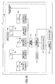
- Fig. 7 is a flowchart showing a procedure for the white reference adjustment processing in the reading controller 106 and image forming processing in the image processor 108.
- the image controller 106 starts its procedure with step S10, where the image controller sets 1 to a counter N.
- step S10 The procedure goes from step S10 to step S11, where the reading controller 106 turns on only the light corresponding to the Nth CIS.
- the procedure goes from the step S11 to a step S12, where the reading controller 106 performs the white reference adjustment processing on the Nth CIS. That is, the reading controller 106 makes the Nth CIS read the reference white board 22, and adjusts the amplification factor of the amplifier corresponding to the Nth CIS so that the peak of the read values becomes a predetermined output value.
- step S12 After the white reference adjustment processing is completed, the procedure goes from step S12 to step S13, where the reading controller 106 turns off the light corresponding to the Nth CIS.
- step S13 the reading controller 106 increases the counter N by one.
- step S15 the reading controller 106 determines if the counter N is larger than Nmax (that is the number of the CISs included in the image reading device 50). If the reading controller 106 determines that the counter N is larger than Nmax (YES at the step S15), the procedure goes to step S16. If the reading controller 106 determines that the counter N is equal to or smaller than Nmax (NO at step S15), the procedure returns to step S11, and repeats the above mentioned steps.
- the image processor 108 forms an image based on read values (white reference values) of the reference white board 22, which have been adjusted for each CIS by the reading controller 106.
- Fig. 8 is a block diagram illustrating a structure of an image forming apparatus according to the second embodiment of the present invention.
- the image forming apparatus 1 in the second embodiment further includes a memory 110.
- the memory 110 stores adjustments values, etc., explained below, in response to a request from the reading controller 106.
- the reading controller 106 When the image forming apparatus 1 is powered on by a user, the reading controller 106 turns on all the lights. Then the reading controller 106 begins the white reference adjustments with the CIS 100 (or the amplifier 1 corresponding to the CIS 100). When the reading controller 106 performs the white reference adjustment on the CIS 100 (or the amplifier 1 corresponding to the CIS 100), it forcibly minimizes the white reference adjustment values of other amplifiers 2-5 corresponding to other CISs 101 ⁇ 104.
- the reading controller 106 first forcibly makes the white reference adjustment values of the amplifiers 2-5 corresponding to the CIS101-104 "1 times" (that is 0 dB, the lowest sensitivity), and then performs the white reference adjustment on CIS 100 (or the amplifier 1 to CIS 100).
- the reading controller 106 adjusts the amplification factor of the amplifier 1 so that the peak of the read values (or the output values) of the reference white board 22 read by the CIS 100 becomes a predetermined output (output reference A in Fig. 6). After the white reference adjustments are completed, the reading controller 106 stores the amplification factor values (adjusted values) after the white reference adjustments into the memory 110.
- the reading controller 106 performs the white reference adjustments on all the CISs (or the amplifiers corresponding to the CISs) in a similar manner. After the completion of the white reference adjustments of all the CISs (or the amplifiers), the reading controller 106 transfers the adjusted values stored in the memory 110 to the corresponding amplifiers 1-5, and turns off all the lights. The reading controller 106 may transfer the adjusted values to the corresponding amplifiers 1-5 after turning off all the lights.
- the peak values of the CISs are set at the reference value A, that is there becomes no variation in the white reference values, as shown in Fig. 6 of the first embodiment.
- the reading controller 106 can remove variation in paper reference values, and reduce the output unevenness of all the pixels of plural CISs to a level that can be corrected by the image processor 108, etc.
- Fig. 9 is a flow chart showing another example of procedure for the white reference adjustment processing in the reading controller 106 and image forming processing in the image processor 108.
- the image controller 106 starts its procedure with step S20, where the image controller 106 sets 1 to a counter N.
- step S20 The procedure goes from step S20 to step S21, where the reading controller 106 turns on all the lights.
- step S21 the reading controller 106 forcibly minimizes the white reference adjustments of the amplifiers (e.g. amplifiers 2-5) corresponding to any CISs (e.g. CIS101-CIS104) other than the Nth CIS (e.g. CIS100).
- the amplifiers e.g. amplifiers 2-5
- any CISs e.g. CIS101-CIS104
- the Nth CIS e.g. CIS100
- step S23 the reading controller 106 performs the white reference adjustment processing on the Nth CIS. That is, the reading controller 106 makes the Nth CIS read the reference white board 22, and adjusts the amplification factor of the amplifier corresponding to the Nth CIS so that the peak of the read values becomes a predetermined output value.
- step S23 the reading controller 106 stores (registers) the adjusted amplification factor (the adjusted value) into the memory 110.
- step 24 goes from step 24 to step 25, where the reading controller 106 increases the counter N by one.
- step S26 the reading controller 106 determines if the counter N is larger than Nmax (that is the number of the CISs included in the image reading device 50). If the reading controller 106 determines that the counter N is larger than Nmax (YES at the step S26), the procedure goes to step S16. If the reading controller 106 determines that the counter N is equal to or smaller than Nmax (NO at step S26), the procedure returns to step S21, and repeats the above mentioned steps.
- the image processor 108 transfers the adjusted values stored in the memory 110 to the corresponding amplifiers (e.g. amplifiers 1 ⁇ 5).
- step S28 the image processor 108 forms an image based on read values (white reference values) of the reference white board 22, which has been adjusted for each CIS by the reading controller 106.
- each of the CISs does not have to have a separate light.
- Fig. 10 is a block diagram of an image forming apparatus according to another embodiment.
- the image forming apparatus 1 shown in Fig. 10 comprises only one light 200, whereby manufacturing cost can be reduced to lower the price of the image forming apparatus.
Landscapes
- Engineering & Computer Science (AREA)
- Multimedia (AREA)
- Signal Processing (AREA)
- Facsimile Scanning Arrangements (AREA)
- Image Input (AREA)
- Facsimile Image Signal Circuits (AREA)
Abstract
Description
- The present invention relates to image reading devices and method, and image forming apparatus and method.
- Prior image forming apparatus compatible with A0 size subject paper uses only one close image sensor (referred to as "CIS" hereinafter). That is, such a prior image forming apparatus uses a CIS having a length of A0 size paper width to read an original subject. However, such prior image forming apparatus is very large and takes high manufacturing cost, resulting in high price of the image forming apparatus.
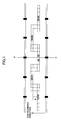
- Therefore, as shown in Fig. 1, an image forming apparatus having 5 CISs equivalent to A4 size paper arranged zigzag is already known.
- In order to accurately read the original subject and obtain good results, it is necessary that the image forming apparatus should correctly recognize white color as reference. Accordingly it is required to adjust the image forming apparatus to make it properly recognize the white color that is called "white color reference adjustment". The white color reference adjustment is a process wherein an output of the CIS reading light generated by a light source is adjusted (gain adjusted) to a predetermined output reference value by an amplifier (or a signal amplifier) before image forming.
- Since a prior image forming apparatus compatible with A0 size paper has only one large CIS, even if a problem occurs in white reference adjusting, it is easy to re-adjust the white reference for the only one CIS during the following image processing step.
- Patent Reference 1: Japanese Patent Laid-open Publication 2001-157006
- However, a prior image forming apparatus compatible with A0 size paper having plural CISs arranged zigzag, has only one amplifier (or signal amplifier), and therefore can adjust one white reference for only one CIS (e.g. CISm shown in Fig. 2), and the other CISs cannot be adjusted, resulting in variations in CIS outputs.
- As a result, each CIS has a different white color reference, and when the same white color is read by plural CISs, some CISs output grey color, providing bad image forming.
- Accordingly, it is a general object of the present invention to provide an image reading device and method in which the white reference value for each CIS is adjusted independently to reduce variation in white reference values of plural CISs and provide a white reference value common to each CIS.
- Features and advantages of the present invention are set forth in the description that follows, and in part will become apparent from the description and the accompanying drawings, or may be learned by practice of the invention according to the teachings provided in the description. Objects as well as other features and advantages of the present invention will be realized and attained by an image reading device and method and an image forming apparatus and method particularly pointed out in the specification in such full, clear, concise, and exact terms as to enable a person having ordinary skill in the art to practice the invention.
- To achieve these and other advantages and in accordance with the purpose of the invention, as embodied and broadly described herein, the invention provides as follows.
- According to one feature of the present invention, there is provided an image reading device having plural image sensors and a reading controller for obtaining image data over a subject by joining sub-image data outputs read by the plural image sensors, each image sensor comprising:
- a signal amplifier; and
- an A/D converter for converting an analog value output from the image sensor to a digital value;
- whereby the reading controller adjusts an amplification factor of each signal amplifier so that a read value of a white board read by each image sensor becomes a predetermined value.
-
- According to another feature of the present invention, there is provided an image forming apparatus including the image reading device as explained above, comprising:
- an image processor for forming an image based on read values of the reference white board adjusted for each image sensor.
-
- According to another feature of the present invention, there is provided an image reading method in an image reading device having plural image sensors and a reading controller, for obtaining image data over a subject by joining sub-image data outputs read by the plural image sensors, each image sensor comprising:
- a signal amplifier; and
- an A/D converter for converting an analog value output from the image sensor to a digital value;
- the image reading method comprising:
- a reading controlling step for adjusting an amplification factor of each signal amplifier so that a read value of a white board read by each image sensor becomes a predetermined value.
-
- According to another feature of the present invention, there is provided an image forming method in an image forming apparatus having plural image sensors and a reading controller, for obtaining an image data over a subject by joining sub-image data outputs read by the plural image sensors, each image sensor comprising:
- a signal amplifier; and
- an A/D converter for converting an analog value output from the image sensor to a digital value;
- the image reading method comprising:
- a reading controlling step for adjusting an amplification factor of each signal amplifier so that a read value of a white board read by each image sensor becomes a predetermined value; and
- an image forming step for forming an image based on read values of the reference white board adjusted for each image sensor.
-
-
- Fig. 1 shows an arrangement of plural CISs in an image reading device;
- Fig. 2 shows a chart illustrating signal levels of plural CISs;
- Fig. 3 generally shows an image forming apparatus to which the present invention may be applied;
- Fig. 4 is a block diagram of an example of an image forming apparatus according to a first embodiment of the present invention;
- Fig. 5 is a cross-sectional view of the image reading device cut by A-A' plane in Fig. 1;
- Fig. 6 is a chart illustrating signal
levels of plural CISs that are adjusted by the
reading controller 106; - Fig. 7 is a flow chart showing procedure for the white reference adjustment processing in the reading controller and image forming processing in the image processor;
- Fig. 8 is a block diagram illustrating a structure of an image forming apparatus according to a second embodiment of the present invention;
- Fig. 9 is a flowchart showing another example of procedure for the white reference adjustment processing in the reading controller and image forming processing in the image processor; and
- Fig. 10 is a block diagram of an image forming apparatus according to another embodiment.
-
- In the following, embodiments of the present invention are described with reference to the accompanying drawings.
- Fig. 3 generally shows an image forming apparatus to which the present invention may be applied. As shown in Fig. 3, the
image forming apparatus 1 comprises animage reader 10, animage writer 11, animage forming unit 12, amanual paper feeder 13, aroll paper feeder 14, and acassette paper feeder 15. - The
image reader 10 corresponds to an image reading device 50 (explained later), and reads image data and the like. Theimage writer 11 responds to image data read by theimage reader 10, and writes the image on a paper fed by theroll paper feeder 14. Theimage forming unit 12 forms an image based on the image data ready by theimage reader 10, to write it on a paper fed by theroll paper feeder 14. Themanual paper feeder 13 is used when a user manually feeds a sheet of paper to theimage forming apparatus 1. Theroll paper feeder 14 supplies a sheet of paper contained in thecassette paper feeder 15 to theimage writer 11. The cassette paper feeder 15 stores sheets of papers put by the user. - Fig. 4 is a block diagram of an example of an
image forming apparatus 1 according to a first embodiment of the present invention. - The
image forming apparatus 1 shown in Fig. 4 comprises animage reading device 50, animage processor 108, and acontroller 109. Theimage reading device 50 comprises plural CISs 100-104 and light sources 200-204. The CISs and the light sources are arranged zigzag. Each of the CISs has N reading pixels, and each CIS 100-104 has a signal amplifier 1-5, and an A/D converter 1-5. Theimage reading device 50 further comprises animage memory 105, a readingcontroller 106 and aninterface 107. - The light sources 200-204 emit light in response to a request from the reading
controller 106 and others. The CISs 100-104 are image sensors that convert light signals (pixels) to electric signals. The amplifiers 1-5 amplify electric signals. The A/D converters 1-5 convert analog values (signals) output from corresponding CIS 100-104 and amplified by corresponding amplifier 1-5 to digital values (signals). - The
image memory 105 relates to image reading and processing, and stores image data. The readingcontroller 106 performs white reference adjustment processing, which is explained later. Theinterface circuit 107 connects theimage reading device 50 to theimage forming apparatus 1, or connects the readingcontroller 106 of theimage reading device 50 to animage processor 108 of theimage forming apparatus 1. - A
controller 109 controls the image forming apparatus overall. Theimage processor 108 forms an image, based on the reading value of the reference white board adjusted by the readingcontroller 106 for each CIS. - The white reference adjustment processing is performed by the reading
controller 106 each time whenever theimage forming apparatus 1 is first started (powered-on) by the user in the morning, or resumed or woken up from sleeping mode. The white reference adjustment process is performed so that the readingcontroller 106 makes the CISs read awhite board 22 shown in Fig. 5. In this embodiment, it is assumed that the CISs of theimage reading device 50 are arranged zigzag as shown in Fig. 1, which does not limit the scope of the present invention. - A cross section of the
image reading device 50 cut by A-A' plane in Fig. 1 is shown in Fig. 5. The cross-sectional view of theimage reading device 50 shown in Fig. 5 corresponds to a portion indicated by A in Fig. 3. - As shown in Fig. 5, the
image reading device 50 includes conveyingrollers 21, a referencewhite board 22 and CIS 1-5. - The conveying
rollers 21 convey an original paper. The referencewhite board 22 is a white board used for white reference adjustment processing. - Fig. 6 shows an example of signal levels of plural CISs, wherein their signal outputs are adjusted (amplification factor adjustment or white reference adjustment) by the reading
controller 106. - When the
image forming apparatus 1 is powered on by a user, the readingcontroller 106 turns on only thelight source 200 corresponding to theCIS 100, and performs the white reference adjustment for the light from thelight source 200. This white reference adjustment processing is processing wherein the readingcontroller 106 adjusts an amplification factor of theamplifier 1 so as to change a peak of a value (or output value) of thewhite reference 22 read byCIS 100 to a predetermined output value (for example, an output value A as shown in Fig. 6). The output value (or analog value) of the CIS after the white reference adjustment processing is converted to a digital value (for example, a digital value of 220 when 8-bit processing is carried out) by an A/D converter. - After the adjustment (white reference adjustment) of the amplification factor of the
amplifier 1 corresponding to theCIS 100, the readingcontroller 106 turns off thelight source 200 corresponding to theCIS 100. At that time, since thelight sources 201~204 corresponding to other CIS 101-104 are also off, A/D converted output values from the CIS 100-104 are zero or close to zero (digital value equivalent to black). - Next, the reading
controller 106 turns on only thelight source 201 corresponding to theCIS 101, and performs the white reference adjustment processing against theamplifier 2 corresponding to theCIS 101. The readingcontroller 106 performs the same processing against the CIS 102-104 (or the amplifiers 3-5 corresponding the CIS 102-104). Then the white reference adjustment is finished for all the CISs (or all the amplifiers). As a result, the peak value of each CIS output value is changed to the reference value A and therefore there becomes no variation in the white reference values. - Since white paper reference values have no variation, image forming disorder or variation can be suppressed in the
image processor 108. That is, by reducing the variation in the white paper reference values, the readingcontroller 106 can reduce the output unevenness over all pixels of the plural CISs to an extent that can be corrected by theimage processor 108. - In the above explained embodiment, the reading
controller 106 performs white reference adjustment on theCIS 100 to begin with. However, it is possible to begin with another CIS for performing white reference adjustment processing. No specific order is required in this and other embodiments. - Fig. 7 is a flowchart showing a procedure for the white reference adjustment processing in the
reading controller 106 and image forming processing in theimage processor 108. - When the
image forming apparatus 1 is turned on, theimage controller 106 starts its procedure with step S10, where the image controller sets 1 to a counter N. - The procedure goes from step S10 to step S11, where the reading
controller 106 turns on only the light corresponding to the Nth CIS. - The procedure goes from the step S11 to a step S12, where the reading
controller 106 performs the white reference adjustment processing on the Nth CIS. That is, the readingcontroller 106 makes the Nth CIS read the referencewhite board 22, and adjusts the amplification factor of the amplifier corresponding to the Nth CIS so that the peak of the read values becomes a predetermined output value. - After the white reference adjustment processing is completed, the procedure goes from step S12 to step S13, where the reading
controller 106 turns off the light corresponding to the Nth CIS. - The procedure goes from step S13 to step S14, where the reading
controller 106 increases the counter N by one. - The procedure goes from step S14 to step S15, where the reading
controller 106 determines if the counter N is larger than Nmax (that is the number of the CISs included in the image reading device 50). If thereading controller 106 determines that the counter N is larger than Nmax (YES at the step S15), the procedure goes to step S16. If thereading controller 106 determines that the counter N is equal to or smaller than Nmax (NO at step S15), the procedure returns to step S11, and repeats the above mentioned steps. - At step S16, the
image processor 108 forms an image based on read values (white reference values) of the referencewhite board 22, which have been adjusted for each CIS by the readingcontroller 106. - The above processing is performed and there becomes no variation in the white reference values and no variation or disorder in image formation.
- Other examples of the
image forming apparatus 1, the white reference adjustment processing carried out by the readingcontroller 106 and image forming processing carried out by theimage processor 108 are shown in a second embodiment. Mainly different points from the first embodiment are explained below. - Fig. 8 is a block diagram illustrating a structure of an image forming apparatus according to the second embodiment of the present invention. The
image forming apparatus 1 in the second embodiment further includes amemory 110. - The
memory 110 stores adjustments values, etc., explained below, in response to a request from the readingcontroller 106. - When the
image forming apparatus 1 is powered on by a user, the readingcontroller 106 turns on all the lights. Then the readingcontroller 106 begins the white reference adjustments with the CIS 100 (or theamplifier 1 corresponding to the CIS 100). When the readingcontroller 106 performs the white reference adjustment on the CIS 100 (or theamplifier 1 corresponding to the CIS 100), it forcibly minimizes the white reference adjustment values of other amplifiers 2-5 corresponding toother CISs 101~104. If the white reference adjustment is done in the range of 1 times - 10 times, the readingcontroller 106 first forcibly makes the white reference adjustment values of the amplifiers 2-5 corresponding to the CIS101-104 "1 times" (that is 0 dB, the lowest sensitivity), and then performs the white reference adjustment on CIS 100 (or theamplifier 1 to CIS 100). - The reading
controller 106, as shown in the first embodiment, adjusts the amplification factor of theamplifier 1 so that the peak of the read values (or the output values) of the referencewhite board 22 read by theCIS 100 becomes a predetermined output (output reference A in Fig. 6). After the white reference adjustments are completed, the readingcontroller 106 stores the amplification factor values (adjusted values) after the white reference adjustments into thememory 110. - The reading
controller 106 performs the white reference adjustments on all the CISs (or the amplifiers corresponding to the CISs) in a similar manner. After the completion of the white reference adjustments of all the CISs (or the amplifiers), the readingcontroller 106 transfers the adjusted values stored in thememory 110 to the corresponding amplifiers 1-5, and turns off all the lights. The readingcontroller 106 may transfer the adjusted values to the corresponding amplifiers 1-5 after turning off all the lights. - As a result of the above white reference adjustment processing according to the second embodiment, the peak values of the CISs are set at the reference value A, that is there becomes no variation in the white reference values, as shown in Fig. 6 of the first embodiment.
- Since there is no variation in white paper reference value, disorder or variation in image forming in the
image processor 108 can be suppressed. That is, the readingcontroller 106 can remove variation in paper reference values, and reduce the output unevenness of all the pixels of plural CISs to a level that can be corrected by theimage processor 108, etc. - Fig. 9 is a flow chart showing another example of procedure for the white reference adjustment processing in the
reading controller 106 and image forming processing in theimage processor 108. - When the
image forming apparatus 1 is turned on, theimage controller 106 starts its procedure with step S20, where theimage controller 106sets 1 to a counter N. - The procedure goes from step S20 to step S21, where the reading
controller 106 turns on all the lights. - The procedure goes from step S21 to step S22, where the reading
controller 106 forcibly minimizes the white reference adjustments of the amplifiers (e.g. amplifiers 2-5) corresponding to any CISs (e.g. CIS101-CIS104) other than the Nth CIS (e.g. CIS100). - The procedure goes from step S22 to step S23, where the reading
controller 106 performs the white reference adjustment processing on the Nth CIS. That is, the readingcontroller 106 makes the Nth CIS read the referencewhite board 22, and adjusts the amplification factor of the amplifier corresponding to the Nth CIS so that the peak of the read values becomes a predetermined output value. - The procedure goes from step S23 to step S24, where the reading
controller 106 stores (registers) the adjusted amplification factor (the adjusted value) into thememory 110. - The procedure goes from step 24 to step 25, where the reading
controller 106 increases the counter N by one. - The procedure goes from step S25 to step S26, where the reading
controller 106 determines if the counter N is larger than Nmax (that is the number of the CISs included in the image reading device 50). If thereading controller 106 determines that the counter N is larger than Nmax (YES at the step S26), the procedure goes to step S16. If thereading controller 106 determines that the counter N is equal to or smaller than Nmax (NO at step S26), the procedure returns to step S21, and repeats the above mentioned steps. - At step 27, the
image processor 108 transfers the adjusted values stored in thememory 110 to the corresponding amplifiers (e.g. amplifiers 1~5). - The procedure goes from step 27 to step S28, where the
image processor 108 forms an image based on read values (white reference values) of the referencewhite board 22, which has been adjusted for each CIS by the readingcontroller 106. - The above processing is performed and there becomes no variation in the white reference values and no variation or disorder in image formation.
- In the second embodiment, each of the CISs does not have to have a separate light.
- Fig. 10 is a block diagram of an image forming apparatus according to another embodiment. The
image forming apparatus 1 shown in Fig. 10 comprises only onelight 200, whereby manufacturing cost can be reduced to lower the price of the image forming apparatus. - As explained above, according to the embodiments of the present invention, there becomes. no variation in the white reference values of the CISs, and it is possible to adjust so that each CIS has a common white reference value.
- The present invention is not limited to these embodiments, but various variations and modifications may be made without departing from the scope of the present invention.
Claims (18)
- An image reading device (50) having a plurality of image sensors (100-104) and a reading controller, for obtaining image data over a subject by joining sub-image data outputs read by the image sensors, each image sensor comprising:whereby the reading controller adjusts an amplification factor of each signal amplifier so that a read value of a white board (22) read by each image sensor becomes a predetermined value.a signal amplifier; andan A/D converter for converting an analog value output from the image sensor to a digital value;
- The image reading device as claimed in Claim 1, wherein the reading controller adjusts the amplification factor of each signal amplifier so that the peak value of the analog value output from the image'sensor becomes equal to the predetermined value.
- The image reading device as claimed in Claim 1, wherein each image sensor further comprises:a light source; andthe reading controller adjusts the amplification factor of each signal amplifier by turning on and off each of the lights in turn.
- The image reading device as claimed in Claim 3, wherein the reading controller does not turn on the lights of any other image sensors other than the image sensor under adjustment, and digital values converted from the analog values output from said any other image sensors are zero or close to zero.
- The image reading device as claimed in Claim 1, further comprising:whereby the reading controller turns on all the lights, minimizes the amplification factors of all the signal amplifiers except one signal amplifier, adjusts the amplification factor of said except one signal amplifier, and stores the adjusted value into the memory.at least one light source; anda memory for storing adjusted values after adjusting the amplification factor of each signal amplifier;
- The image reading device as claimed in Claim 5, wherein the reading controller adjusts the amplification factors of all the signal amplifiers, and then takes out the adjusted values from the memory, and gives the adjusted values to corresponding signal amplifiers.
- The image reading device as claimed in Claim 5, wherein one of the lights is provided for each image sensor.
- The image reading device as claimed in claim 5, wherein only one light is provided in common to all the image sensors.
- An image forming apparatus including the image reading device as claimed in Claim 1, comprising:an image processor for forming an image based on read values of the reference white board adjusted for each image sensor.
- An image reading method in an image reading device having a plurality of image sensors and a reading controller, for obtaining image data over a subject by joining sub-image data outputs read by the image sensors, each image sensor including
a signal amplifier; and
an A/D converter for converting an analog value output from the image sensor to a digital value;
the image reading method comprising:a reading controlling step for adjusting an amplification factor of each signal amplifier so that a read value of a white board read by each image sensor becomes a predetermined value. - The image reading method as claimed in Claim 10, wherein the reading controlling step adjusts the amplification factor of each signal amplifier so that the peak value of the analog value output from the image sensor becomes equal to the predetermined value.
- The image reading method as claimed in Claim 10, wherein each image sensor further comprises:a light source; andthe reading controlling step adjusting the amplification factor of each signal amplifier by turning on and off each of the lights in turn.
- The image reading method as claimed in Claim 12, wherein the reading controlling step does not turn on the lights of any other image sensors other than the image sensor under adjustment, and digital values converted from the analog values output from said any other image sensors are zero or close to zero.
- The image reading method as claimed in Claim 10, further comprising:whereby the reading controlling step turns on all the lights, minimizes the amplification factors of all the signal amplifiers except one signal amplifier, adjusts the amplification factor of said except one signal amplifier, and stores the adjusted value into the memory.at least one light source; anda memory for storing adjusted values after adjusting the amplification factor of each signal amplifier;
- The image reading device as claimed in Claim 14, wherein the reading controlling step adjusts the amplification factors of all the signal amplifiers, and then takes out the adjusted values from the memory, and gives the adjusted values to corresponding signal amplifiers.
- The image reading method as claimed in Claim 14, wherein one of the lights is provided for each image sensor.
- The image reading method as claimed in claim 14, wherein only one light is provided in common to all the image sensors.
- An image forming method in an image forming apparatus having a plurality of image sensors and a reading controller for obtaining image data over a subject by joining sub-image data outputs read by the plural image sensors, each image sensor including
a signal amplifier; and
an A/D converter for converting an analog value output from the image sensor to a digital value;
the image reading method comprising:a reading controlling step for adjusting an amplification factor of each signal amplifier so that a read value of a reference white board read by each image sensor becomes a predetermined value; andan image forming step for forming an image based on the read values of the reference white board adjusted for each image sensor.
Applications Claiming Priority (4)
| Application Number | Priority Date | Filing Date | Title |
|---|---|---|---|
| JP2003410577 | 2003-12-09 | ||
| JP2003410577 | 2003-12-09 | ||
| JP2004324893 | 2004-11-09 | ||
| JP2004324893A JP4464253B2 (en) | 2003-12-09 | 2004-11-09 | Image reading apparatus, image forming apparatus, image reading method, and image forming method |
Publications (2)
| Publication Number | Publication Date |
|---|---|
| EP1542446A1 true EP1542446A1 (en) | 2005-06-15 |
| EP1542446B1 EP1542446B1 (en) | 2011-08-10 |
Family
ID=34525494
Family Applications (1)
| Application Number | Title | Priority Date | Filing Date |
|---|---|---|---|
| EP04029265A Expired - Lifetime EP1542446B1 (en) | 2003-12-09 | 2004-12-09 | An image reading device and method, and an image forming apparatus and method |
Country Status (4)
| Country | Link |
|---|---|
| US (1) | US7755803B2 (en) |
| EP (1) | EP1542446B1 (en) |
| JP (1) | JP4464253B2 (en) |
| CN (1) | CN100403763C (en) |
Families Citing this family (2)
| Publication number | Priority date | Publication date | Assignee | Title |
|---|---|---|---|---|
| US7889404B2 (en) | 2007-05-31 | 2011-02-15 | Ricoh Company, Ltd. | Image reading device, image forming apparatus, and reading-unit install method |
| JP5438331B2 (en) * | 2009-01-30 | 2014-03-12 | 浜松ホトニクス株式会社 | Solid-state imaging device |
Citations (11)
| Publication number | Priority date | Publication date | Assignee | Title |
|---|---|---|---|---|
| JPS63314959A (en) | 1987-06-17 | 1988-12-22 | Minolta Camera Co Ltd | Color image input device |
| JPH034676A (en) * | 1989-06-01 | 1991-01-10 | Canon Inc | Image reading device |
| US5028783A (en) * | 1988-08-24 | 1991-07-02 | Fuji Photo Film Co., Ltd. | Shading elimination method for an image read-out apparatus |
| JPH08181859A (en) * | 1994-12-26 | 1996-07-12 | Nikon Corp | Image reading system |
| US6011636A (en) * | 1995-10-13 | 2000-01-04 | Fuji Photo Film Co., Ltd. | Method of controlling exposure in film scanner |
| US6188493B1 (en) * | 1997-04-18 | 2001-02-13 | Matsushita Electric Industrial Co., Ltd. | Electronic blackboard device |
| JP2001157006A (en) | 1999-11-30 | 2001-06-08 | Ricoh Co Ltd | Image reading processing system |
| US6292269B1 (en) * | 1997-11-26 | 2001-09-18 | Ricoh Company, Ltd. | Method and apparatus for image reading capable of detecting dust that disturbs image reading operation |
| US6304826B1 (en) * | 1999-02-05 | 2001-10-16 | Syscan, Inc. | Self-calibration method and circuit architecture of image sensor |
| JP2002199218A (en) * | 2000-12-26 | 2002-07-12 | Canon Inc | Image reader and image processing method, and storage medium |
| US20020122213A1 (en) * | 2001-03-01 | 2002-09-05 | Hill Edward A. | Correction for debris and low output photosensors in scroll fed scanner using stored initial calibration data |
Family Cites Families (9)
| Publication number | Priority date | Publication date | Assignee | Title |
|---|---|---|---|---|
| JPS61120570A (en) * | 1984-11-16 | 1986-06-07 | Ricoh Co Ltd | Image reader |
| JPS6212267A (en) | 1985-07-09 | 1987-01-21 | Tokyo Electric Co Ltd | optical reader |
| US4862286A (en) | 1986-11-14 | 1989-08-29 | Canon Kabushiki Kaisha | Image reading apparatus which adjusts image signals to improve signal balance |
| JP2617925B2 (en) | 1986-11-14 | 1997-06-11 | キヤノン株式会社 | Image reading device |
| US5130788A (en) * | 1987-05-21 | 1992-07-14 | Minolta Camera Kabushiki Kaisha | Shading correction using FIFO memory for correction data |
| US5151796A (en) * | 1989-03-29 | 1992-09-29 | Canon Kabushiki Kaisha | Image reading apparatus having a D/A converter with a controllable output |
| JP2507675B2 (en) | 1990-06-21 | 1996-06-12 | 富士通株式会社 | Shading correction method for optical line sensor |
| JP3276026B2 (en) | 1993-11-25 | 2002-04-22 | 富士ゼロックス株式会社 | Image data adjustment method for image reading device |
| JPH10215374A (en) | 1997-01-29 | 1998-08-11 | Ricoh Co Ltd | Reading device and control method thereof |
-
2004
- 2004-11-09 JP JP2004324893A patent/JP4464253B2/en not_active Expired - Fee Related
- 2004-12-08 US US11/006,637 patent/US7755803B2/en not_active Expired - Fee Related
- 2004-12-09 CN CNB2004101037372A patent/CN100403763C/en not_active Expired - Fee Related
- 2004-12-09 EP EP04029265A patent/EP1542446B1/en not_active Expired - Lifetime
Patent Citations (11)
| Publication number | Priority date | Publication date | Assignee | Title |
|---|---|---|---|---|
| JPS63314959A (en) | 1987-06-17 | 1988-12-22 | Minolta Camera Co Ltd | Color image input device |
| US5028783A (en) * | 1988-08-24 | 1991-07-02 | Fuji Photo Film Co., Ltd. | Shading elimination method for an image read-out apparatus |
| JPH034676A (en) * | 1989-06-01 | 1991-01-10 | Canon Inc | Image reading device |
| JPH08181859A (en) * | 1994-12-26 | 1996-07-12 | Nikon Corp | Image reading system |
| US6011636A (en) * | 1995-10-13 | 2000-01-04 | Fuji Photo Film Co., Ltd. | Method of controlling exposure in film scanner |
| US6188493B1 (en) * | 1997-04-18 | 2001-02-13 | Matsushita Electric Industrial Co., Ltd. | Electronic blackboard device |
| US6292269B1 (en) * | 1997-11-26 | 2001-09-18 | Ricoh Company, Ltd. | Method and apparatus for image reading capable of detecting dust that disturbs image reading operation |
| US6304826B1 (en) * | 1999-02-05 | 2001-10-16 | Syscan, Inc. | Self-calibration method and circuit architecture of image sensor |
| JP2001157006A (en) | 1999-11-30 | 2001-06-08 | Ricoh Co Ltd | Image reading processing system |
| JP2002199218A (en) * | 2000-12-26 | 2002-07-12 | Canon Inc | Image reader and image processing method, and storage medium |
| US20020122213A1 (en) * | 2001-03-01 | 2002-09-05 | Hill Edward A. | Correction for debris and low output photosensors in scroll fed scanner using stored initial calibration data |
Non-Patent Citations (4)
| Title |
|---|
| PATENT ABSTRACTS OF JAPAN vol. 013, no. 164 (E - 745) 19 April 1989 (1989-04-19) * |
| PATENT ABSTRACTS OF JAPAN vol. 015, no. 114 (E - 1047) 19 March 1991 (1991-03-19) * |
| PATENT ABSTRACTS OF JAPAN vol. 1996, no. 11 29 November 1996 (1996-11-29) * |
| PATENT ABSTRACTS OF JAPAN vol. 2002, no. 11 6 November 2002 (2002-11-06) * |
Also Published As
| Publication number | Publication date |
|---|---|
| CN100403763C (en) | 2008-07-16 |
| JP4464253B2 (en) | 2010-05-19 |
| CN1645893A (en) | 2005-07-27 |
| US20050141049A1 (en) | 2005-06-30 |
| EP1542446B1 (en) | 2011-08-10 |
| JP2005198258A (en) | 2005-07-21 |
| US7755803B2 (en) | 2010-07-13 |
Similar Documents
| Publication | Publication Date | Title |
|---|---|---|
| US8064105B2 (en) | Image scanning device and image forming device | |
| EP0999697B1 (en) | An image scanner having image correcting function | |
| US7782496B2 (en) | Image signal processing circuit, image reading device, and image forming apparatus | |
| US8259371B2 (en) | Image reading apparatus, image reading method, program and recording medium for color processing parameter adjustment using a first color processing step on an image read from a front side of a document and a second color processing step on an image read from a back side of the document | |
| US20050206981A1 (en) | Method and apparatus for improving quality of scanned image through preview operation | |
| US5325210A (en) | Shading data accepting system in image readers | |
| US7616351B2 (en) | Image reading device | |
| US20030142367A1 (en) | Image reader | |
| EP1542446B1 (en) | An image reading device and method, and an image forming apparatus and method | |
| EP0964569B1 (en) | Image reading apparatus | |
| JP2008278277A (en) | Image reading device | |
| US6611360B1 (en) | Image reading apparatus | |
| JP4107635B2 (en) | Image reading device | |
| JPH06189132A (en) | Image reader | |
| JP2002057899A (en) | Image reading device and image forming device | |
| JP2004040443A (en) | Image reading device and image processing device | |
| JP2014197814A (en) | Image reading device, image forming apparatus, and image reading method | |
| JP4124394B2 (en) | Color image reading apparatus and image forming apparatus | |
| JP3378750B2 (en) | Image scanner | |
| JP2001157006A (en) | Image reading processing system | |
| JP2612211B2 (en) | Image input device | |
| JP3347787B2 (en) | Image density correction method in image reading device | |
| JP3441626B2 (en) | Image reading device | |
| JP2021125815A (en) | Image reader | |
| JP2002374393A (en) | Image reading apparatus and image reading method |
Legal Events
| Date | Code | Title | Description |
|---|---|---|---|
| PUAI | Public reference made under article 153(3) epc to a published international application that has entered the european phase |
Free format text: ORIGINAL CODE: 0009012 |
|
| 17P | Request for examination filed |
Effective date: 20041209 |
|
| AK | Designated contracting states |
Kind code of ref document: A1 Designated state(s): AT BE BG CH CY CZ DE DK EE ES FI FR GB GR HU IE IS IT LI LT LU MC NL PL PT RO SE SI SK TR |
|
| AX | Request for extension of the european patent |
Extension state: AL BA HR LV MK YU |
|
| AKX | Designation fees paid |
Designated state(s): AT BE BG |
|
| RBV | Designated contracting states (corrected) |
Designated state(s): DE FR GB |
|
| REG | Reference to a national code |
Ref country code: DE Ref legal event code: 8566 |
|
| 17Q | First examination report despatched |
Effective date: 20070312 |
|
| GRAP | Despatch of communication of intention to grant a patent |
Free format text: ORIGINAL CODE: EPIDOSNIGR1 |
|
| GRAS | Grant fee paid |
Free format text: ORIGINAL CODE: EPIDOSNIGR3 |
|
| GRAA | (expected) grant |
Free format text: ORIGINAL CODE: 0009210 |
|
| RIN1 | Information on inventor provided before grant (corrected) |
Inventor name: BABA, TORU, C/O RICOH UNITECHNO CO.,LTD. |
|
| AK | Designated contracting states |
Kind code of ref document: B1 Designated state(s): DE FR GB |
|
| REG | Reference to a national code |
Ref country code: GB Ref legal event code: FG4D |
|
| REG | Reference to a national code |
Ref country code: DE Ref legal event code: R096 Ref document number: 602004033831 Country of ref document: DE Effective date: 20111006 |
|
| PLBE | No opposition filed within time limit |
Free format text: ORIGINAL CODE: 0009261 |
|
| STAA | Information on the status of an ep patent application or granted ep patent |
Free format text: STATUS: NO OPPOSITION FILED WITHIN TIME LIMIT |
|
| 26N | No opposition filed |
Effective date: 20120511 |
|
| REG | Reference to a national code |
Ref country code: DE Ref legal event code: R097 Ref document number: 602004033831 Country of ref document: DE Effective date: 20120511 |
|
| REG | Reference to a national code |
Ref country code: FR Ref legal event code: PLFP Year of fee payment: 12 |
|
| REG | Reference to a national code |
Ref country code: FR Ref legal event code: PLFP Year of fee payment: 13 |
|
| PGFP | Annual fee paid to national office [announced via postgrant information from national office to epo] |
Ref country code: GB Payment date: 20161222 Year of fee payment: 13 Ref country code: DE Payment date: 20161213 Year of fee payment: 13 |
|
| PGFP | Annual fee paid to national office [announced via postgrant information from national office to epo] |
Ref country code: FR Payment date: 20161222 Year of fee payment: 13 |
|
| REG | Reference to a national code |
Ref country code: DE Ref legal event code: R119 Ref document number: 602004033831 Country of ref document: DE |
|
| GBPC | Gb: european patent ceased through non-payment of renewal fee |
Effective date: 20171209 |
|
| REG | Reference to a national code |
Ref country code: FR Ref legal event code: ST Effective date: 20180831 |
|
| PG25 | Lapsed in a contracting state [announced via postgrant information from national office to epo] |
Ref country code: FR Free format text: LAPSE BECAUSE OF NON-PAYMENT OF DUE FEES Effective date: 20180102 Ref country code: DE Free format text: LAPSE BECAUSE OF NON-PAYMENT OF DUE FEES Effective date: 20180703 |
|
| PG25 | Lapsed in a contracting state [announced via postgrant information from national office to epo] |
Ref country code: GB Free format text: LAPSE BECAUSE OF NON-PAYMENT OF DUE FEES Effective date: 20171209 |