BACKGROUND OF THE INVENTION
FIELD OF THE INVENTION
This invention relates to a computer network technique, more particularly, to a
method of peer-to-peer connecting devices when implementing dynamic
networking and resource sharing in a home network.
DESCRIPTION OF THE PRIOR ART
With the rapid development of computer and network technologies and individual
requirements to digitalization and informatization of lives, Home Network (such as
Smart Home, Electronic Home, e-Home, Digital Family, Network Home, and
Intelligent Home) has been developed as a hot technique. The home network
technique is a key one for implementing digitalization of home devices. With this
technique, all electrical devices in a home can be connected as a whole so as to
achieve device interconnection and information transmission at anytime and
anywhere.
The requirements to the home network are completely different from those to a
commercial network, such as it does not need any additional wiring, and should be
easy to use, low cost and so on. The existing network techniques suitable to home
device interconnection such as HomePNA can implement interconnections of
digital devices by means of existing telephone line of each home, and easy to use
without influencing normal reception of a call. The automatic control of home
electrical appliances can be conveniently implemented by networking with a power
line equipped in the home in which signals and data are transmitted.
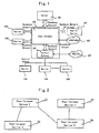
Fig.1 shows a topological structure of digital home network architecture,
hierarchically including a backbone network and a control subnet. The networking
forms of a home backbone network includes two parts of a wired access (a wired
backbone network) and a wireless access (a wireless backbone network) (in order
to implement interconnections of some wireless devices and make users enjoy
information access without limitation of time and location, the wireless backbone
network is an indispensable part of the home backbone network). Generally, in the
backbone network, there is one home network server 101 which is a processing
center and a storing center of the digital home and can be one PC device or a
dedicated server. A home gateway 102 in the backbone network is used to effect
the interconnections among an internal device 104 of the home network and a
mobile device 103 and a broadband access of the home such that the devices 103
and 104 in the home backbone network can share the information from Internet
105. The home backbone network constitutes a home information/multimedia
network and implements the interconnections and resource sharing among
information devices, communication devices, entertainment devices and the like.
The preliminary data transmitted by the home backbone network are text, picture,
audio and video etc.
The control subnet is used to effect the interconnections among devices (108) such
as home electrical appliances, automatic devices and security (monitoring)
apparatuses; its constitution is an important premise for achieving home
automation. The data transmitted in the control subnet are mainly various control
instructions to devices and status data of devices. A control gateway 106 in the
control subnet, on one hand, implements the interconnections among various home
devices 108, and on the other hand, implements the interconnections between the
control subnet and the backbone network, and also provides external interfaces for
a remote telephone alarm and a telephone remote control (implemented with Public
Switched Telephone Network (PSTN) 107).
The interactions between the home backbone network and the Internet 105 have
two hierarchical meanings: (1) a user may invoke services on the home backbone
network remotely through the Internet; and (2) the user may access services on the
Internet through the home backbone network.
The interactions between the home backbone network and the home control
subnet are implemented by the control gateway 106. The control gateway 106 is
responsible for performing protocol conversion between the backbone network and
the control subnet such that the services in the control subnet are represented as
services in the home backbone network. The operations to devices and services in
the control subnet are converted into the operations to the corresponding services
on the control gateway 106. In control subnet protocols, the descriptions about
services are all described based on XML language. With respect to services in the
control subnet, the control gateway 106 generates corresponding XML descriptions
and these services are registered as backbone network services onto the control
gateway 106.
In order to make users enjoy entertainments freely and lives comfortable, those
various and complex electrical devices in home must be interconnected organically
and cooperated. Therefore, in the backbone network of the home network
architecture, the objects of high-rates transmission, high-quality services, dynamic
networking and effective resource sharing of the home backbone network will be
achieved by designing a reasonable and effective method (backbone network
protocols) for dynamic networking and sharing resources among the devices.
In the present invention, supporting dynamic networking among various devices in
home refers to that without performing network parameters configuration in a
manual manner in advance, a device in the network can dynamically select
relevant devices from the network so as to form a home network, which is used to
implement a function that cannot be fulfilled with any single device, or to improve
the performance of an original function of any single device. Resource sharing
means that a device in the network can issue resources provided by itself, and can
also retrieve and utilize resources provided by other devices. A direct
communication and resource sharing between any two devices are implemented to
extent the functions of single device.
A method for implementing dynamic networking and resource sharing among
devices in a home backbone network may include the steps of:
Actually, the implementing procedure of service utilizing devices or service
providing devices constituting a home network in a peer-to-peer connecting manner
in step D of the above solution is the method of peer-to-peer connecting the
devices during dynamic networking to be solved by the present invention.
SUMMARY OF THE INVENTION
Therefore, an object of the present invention is to provide a device peer-to-peer
connecting method for implementing dynamic networking in a backbone network of
a home network. In the range of the home, a premise is prepared for dynamically
generating the backbone network of the home network and resource sharing
thereof, that is, a connecting method is designed for implementing the peer-to-peer
connections of devices.
The members of the home backbone network involved in the inventive method
include information devices, communication devices and entertainment devices etc.,
and can also interact with some home electrical appliances such as refrigerator,
washing machine, television set and audio device in a manner of protocol gateway.
Thus, the device involved in the inventive method refers to a carrier for providing or
accepting services.
The service involved in the inventive method refers to a functional entity running on
a device and satisfying a standard interface defined by a backbone network
protocol.
The resource management device involved in the inventive method refers to a
device being able to provide registration and service indexing functions to devices
in the network.
The service providing device involved in the inventive method refers to a device
providing services to other devices in the network.
The service utilizing device involved in the inventive method refers to a device
utilizing services provided by other devices in the network.
The multicast involved in the inventive method refers to one sending device
sending information to a certain group of receiving devices, and the unicast
involved in the inventive method refers to one sending device sending information
to one designated receiving device.
The object of the prevent invention is achieved by the following technical solutions.
A method of peer-to-peer connecting devices when implementing dynamic
networking in a home network, including a connection creating method and a
connection disconnecting method of peer-to-peer devices, which is characterized in
that:
In the step b, the connection target device also saves the connection challenge
value; in the step c, the connection initiating device retrieves key information
corresponding to the connection challenge value and generates the connection
reply value together with the connection challenge value; in the step d, the
connection target device judges validity of the connection reply value according to
the saved connection challenge value and the key corresponding to this connection
challenge value, and when it is valid, sends a connection response message about
success of connection to the connection initiating device, and when it is invalid,
sends a connection response message about denial of access to the connection
initiating device.
The connection initiating device is a service providing device or a service utilizing
device. The connection target device is a service utilizing device or a service
providing device.
According to the inventive method, a device in a network can search other devices
and services thereon by means of a device discovering protocol. A service utilizing
device can initiate a device connection creating request to a found service
providing device so as to create a peer-to-peer connection.
After receiving the device connection creating request initiated by the service
utilizing device, the service providing device sends out a connection creating
response message.
After the peer-to-peer connection is established between the service utilizing
device and the service providing device, a transmission key is generated according
to an encryption method defined in security mechanism in order to transmit
subsequent data.
After the service utilizing device and the service providing device create the
peer-to-peer connection, the service utilizing device initiates a service searching
procedure to the service providing device so as to acquire detailed service
information on the service providing device, initiates a service renting procedure to
the service providing device so as to acquire a right to utilize the service, and
initiates a service invoking request to the service providing device so as to utilize
the service.
When the service utilizing device does not need the service of the service providing
device any more, it can disconnect the connection with the service providing device
at anytime. The service providing device in one peer-to-peer connection relation
can disconnect the connection with the service utilizing device at anytime.
In the home network, with the inventive device peer-to-peer connecting method, the
dynamic networking among any peer-to-peer devices within the network range
without a resource management device can be simply implemented.
BRIEF DESCRIPTION OF THE DRAWINGS
Figure 1 is a diagram of a topological structure of a digital home network
architecture.
Figure 2 is a schematic diagram of a network structure when performing a
peer-to-peer connection in a home network device management.
Figure 3 is flow chart of a device peer-to-peer connecting procedure of a inventive
method.
DETAILED DESCRIPTION OF THE PREFERRED EMBODIMENTS
The key idea of a home network is to implement interconnection and
communication as well as resource sharing among devices dynamically. When
there is a master control device, that is, a resource management device, in the
network, a centralized management to devices can be achieved by registration and
cancellation procedures of the master control device to various devices in the
network. However, not in all home network environments, there will be a stationary
resource management device. Therefore, the method according to the present
invention is adapted to a home network environment without a resource
management device. A simple device management is achieved by a peer-to-peer
connecting mechanism among peer-to-peer devices so as to achieve the
interconnection and communication as well as resource sharing among devices.
For the convenience of describing the inventive device peer-to-peer connecting
method, the home network structure of Fig. 1 can be simplified as the structure as
shown in Fig. 2.
Referring to Fig. 2, a plurality of information devices are included in the composition
of home electrical appliances, for example, a peer-to-peer device 1 (21), a
peer-to-peer device 2 (22), a peer-to-peer device 3 (23) and a peer-to-peer device
4 (24). A peer-to-peer device can refer to either a service providing device or a
service utilizing device. There is no resource management device in a peer-to-peer
connected home network.
In the method according to the invention, when a peer-to-peer device connection is
performed, there is one connection initiating device and one connection target
device. In which, the connection target device is designated by the connection
initiating device. A piece of software is necessarily added into the both devices to
perform communications therebetween so as to implement a peer-to-peer
connection.
A device discovering procedure is prior to the connection of devices, and is
performed between the connection initiating device and the connection target
device. The connection initiating device firstly discovers the connection target
device through the device discovering procedure, and whereby can start a device
connecting procedure.
As described in the Background of The Invention, in the implementing method of
dynamic networking and resource sharing, steps B and C are the device
discovering procedure, and include two procedures of device announcing and
device searching.
When the devices in the home network are powered on, the software running
thereon announces its own existence information and relevant security requirement
information into the network in a multicasting manner according to the device
announcing method. The devices in the network can acquire the existence
information of other devices by intercepting such device announcement information
(including type of device, IP address of device and service information provided by
the device). The devices in the network can send device searching information in a
multicasting manner. When a device receiving the multicast searching information
finds that its own conditions is consistent with the searching conditions in the
searching request, it returns announcement information of itself in a unicasting
manner. By means of such device announcing and device searching steps, all
devices in the home network can discover each other.
Referring to Fig. 3, the steps as shown represent a connecting procedure of
peer-to-peer devices. The connecting procedure starts with sending a device
connecting request, by a connection initiating device, to a connection target device.
If the security property of a service providing device is set as that authentication is
needless (which is set in the device announcement), then the service providing
device allows connection creating request of anyone of service utilizing devices,
and sends a connection creating response message to the service utilizing device.
If the security property of a service providing device is set as that authentication is
needed (which is set in the device announcement), the service providing device
and the service utilizing device apply a connection creation process in accordance
with the steps shown in the drawing. An entire device connecting procedure
includes 8 steps of key configuration and connection request sending, connection
request processing, connection challenge value sending, connection challenge
value processing, connection reply value sending, connection reply value
processing, connection response value sending, and connection response value
processing.
Before performing Step 1, a device information setting and a key configuration are
necessarily performed. The administrator of the home network performs connection
setting for all devices (connection initiating devices and connection target devices)
desiring to support peer-to-peer connections, which includes configuring account
information allowing to connect which comprises user name and password for all
devices, in which when the devices themselves have a human-machine interface,
the configuration is performed through the human-machine interface, whereas for
those devices without a human-machine interface, a remote setting to them can be
performed through a device with a human-machine interface; and further
configuring an allowed maximum parallel connection number for each device.
In Step 1, key configuration and connection request sending, a connection initiating
device (such as a service utilizing device) sends it to a connection target device
(such as a service providing device), the device connecting procedure starts.
The device connecting request information sent from the connection initiating
device to the connection target device includes four fields of type of message,
serial number of message, user name and serial number of connection request.
The names, content and value ranges of respective fields are as shown in the
following table.
| Field Name | Content | Value Range |
| Type of message | connection creating request | a character string (ConnectRequest) |
| Serial number of message | serial number of protocol message | an unsigned integer more than 1 |
| User name | indicating user's information of the device | a character string whose length is more than 1 and less than 32 |
| Serial number of connection request | request's serial number during the connecting procedure | [1] |
In Step 2, connection request processing, the connection target device conducts
processing. When the connection target device receives the connection request
from the connection initiating device, it firstly judges whether the number of
connection initiating devices currently connected with the present connection target
device has reached the upper limit of the allowed connection number. If so, it
returns a connection response message whose connecting result is overload
(OVERLOAD) in a subsequent step, and this device connecting procedure is ended.
Otherwise, it further judges whether the user information of the connection initiating
device is in the present connection target device according to the user information
indicated in the device connecting request. If not so, then it returns a connection
response message whose connecting result is denial of access (ACCESSDENIED).
Otherwise, a challenge value whose length is 32 bits are randomly generated, and
based on which, a connection challenge value message is generated in order to be
sent to the connection initiating device, and the challenge value is also saved for
later usages (such as waiting for the arrival of a response value so as to make a
comparison).
In Step 3, connection challenge value sending, the connection target device sends
it to the connection initiating device.
The procedure of sending the connection challenge value is also the procedure of
the service providing device sending the connection creating response message to
the service utilizing device. The connecting result is included in the response
message in order to notify the service utilizing device of carrying out corresponding
process according to the result. The response message also includes an identity
authenticating algorithm identifier ID used by the service providing device and the
challenge value ChallengeValue randomly selected by the service utilizing device.
The names, contents and value ranges of respective fields of the connection
creating response message are as shown in the following table.
| Field Name | Content | Value Range |
| Type of message | connection creating response | ConnectResponse |
| Serial number of message | serial number of protocol message | an unsigned integer more than 1 |
| Serial number of connection response | serial number of connection response | 1 |
| Connecting result | reply character string | SUCCESS or OVERLOAD or ACCESSDENIED or AUTHENTICATE |
| Identity authenticating algorithm | authenticating algorithm identifier ID | ShareKey |
| Challenge value | ChallengeValue | a 32 bits long character string |
In Step 4, connection challenge value processing, it is carried out by the connection
initiating device. After receiving the connection challenge value message, the
connection initiating device should retrieve whether there is key information
corresponding to the challenge value in the device itself. If there isn't, then the
present connection is failed, and the present connecting procedure is ended.
Otherwise, a reply value (a response value, Response) should be generated in
accordance with the security mechanism according to the challenge value and the
key (after receiving the identity authenticating algorithm identifier ID and the
challenge value, the connection initiating device encrypts the challenge value with
its own key), and is sent to the connection target device.
In
Step 5, connection reply value sending, after generating the connection reply
value, the connection initiating device sends it to the connection target device. This
connection reply message includes four fields of type of message, serial number of
message, serial number of connection request and reply value. The names,
contents and value ranges of respective fields are as shown in the following table.
| Field Name | Content | Value Range |
| Type of message | connection creating request | ConnectRequest |
| Serial number of message | serial number of protocol message | an unsigned integer more than 1 |
| Serial number of connection request | request's serial number during the connecting procedure | 2 |
| Reply value | reply character string | a 32 bits long character string |
In Step 6, connection reply value processing, it is carried out by the connection
target device. After receiving the connection reply value sent from the connection
initiating device, the connection target device should judge whether this reply value
is valid according to the saved challenge value and its corresponding key. If it is
valid, the connection target device sends a connection response message
containing success of connection to the connection initiating device; otherwise, a
connection response message containing information about wrong key is sent.
Specifically, the connection target device decrypts the challenge value with a
shared key KeyID corresponding to the ID announced by the connection initiating
device. If Response = Encrypt (KeyID, ChallengeValue), then the connection is
allowed to be created, and also a response of connection success is sent to the
connection initiating device, and the environment of connection is prepared. If
Response <> Encrypt (KeyID, ChallengeValue), then the connection is not allowed
to be created, and also a response of creation failure is sent to the service utilizing
device, and the information corresponding to the device is deleted.
If the connection target device regards that the present connection is successful,
then the connection numbers of both devices connected should be increased.
In which, the judgment whether the configuration of the key and the reply value is
valid or not should be carried out in accordance with the security mechanism.
In Step 7, connection response message sending, the connection target device
sends it to the connection initiating device. The connection target device sends a
connection response message according to the result of reply value processing.
The connection response message includes four fields of type of message, serial
number of message, serial number of connection response message and
connecting result. The names, contents and value ranges of respective fields are
as shown in the following table.
| Field Name | Content | Value Range |
| Type of message | connection creating response | ConnectResponse |
| Serial number of message | serial number of protocol message | an unsigned integer more than 1 |
| Serial number of connection response message | serial number of connection response message | 2 |
| Connecting result | reply character string | SUCCESS or OVERLOAD or ACCESSDENIED or |
| | | AUTHENTICATE |
In Step 8, connection response message processing, it is carried out by the
connection initiating device. After receiving the connection response message, the
connection initiating device can immediately judge the present connection is
successful or not.
After the connection relation is established between two devices, a connection
disconnection can be performed at anytime. The connection disconnection includes
two steps of connection disconnecting request and connection disconnecting
request message processing.
During the connection disconnecting request, any one of the devices (the initiating
connection device or the target connection device) can both initiate a connection
disconnecting request to the other device at any time to disconnect the established
connection. The sent connection disconnecting request message includes three
fields of type of message, serial number of message and reason for disconnecting
connection (normal or protoerror). The names, contents and value ranges of
respective fields are as shown in the following table.
| Field Name | Content | Value Range |
| Type of message | connection disconnecting message | Disconnect |
| Serial number of message | serial number of protocol message | an unsigned integer more than 1 |
| Reason for disconnecting connection | reasons for disconnecting the connection | NORMAL or PROTOERROR |
In order to ensure that no fraudulent device connection disconnecting request
occurs, the sending of the device connection disconnecting request should be
transmitted according to the encrypting method defined in the security mechanism.
During the connection disconnecting message processing, when any one of the
devices with an established connection relation receives the connection
disconnecting request from the other device, it regards that the present connection
is disconnected, and at the same time, the both devices should decrease the
connection numbers thereof.
In the inventive method, the devices in the network are managed, connection and
disconnection among various devices are implemented and the dynamic
networking and resource sharing in the extent of home network when there is not
resource management device are achieved by means of a peer-to-peer connection
mechanism cooperating with the home backbone network protocol.