EP1542254A2 - Slot motor including legs engaging openings of circuit breaker housing and electrical switching apparatus employing the same - Google Patents
Slot motor including legs engaging openings of circuit breaker housing and electrical switching apparatus employing the same Download PDFInfo
- Publication number
- EP1542254A2 EP1542254A2 EP04029365A EP04029365A EP1542254A2 EP 1542254 A2 EP1542254 A2 EP 1542254A2 EP 04029365 A EP04029365 A EP 04029365A EP 04029365 A EP04029365 A EP 04029365A EP 1542254 A2 EP1542254 A2 EP 1542254A2
- Authority
- EP
- European Patent Office
- Prior art keywords
- circuit breaker
- housing
- slot motor
- opening
- motor assembly
- Prior art date
- Legal status (The legal status is an assumption and is not a legal conclusion. Google has not performed a legal analysis and makes no representation as to the accuracy of the status listed.)
- Withdrawn
Links
Images




Classifications
-
- H—ELECTRICITY
- H01—ELECTRIC ELEMENTS
- H01H—ELECTRIC SWITCHES; RELAYS; SELECTORS; EMERGENCY PROTECTIVE DEVICES
- H01H71/00—Details of the protective switches or relays covered by groups H01H73/00 - H01H83/00
- H01H71/02—Housings; Casings; Bases; Mountings
- H01H71/025—Constructional details of housings or casings not concerning the mounting or assembly of the different internal parts
- H01H71/0257—Strength considerations
-
- H—ELECTRICITY
- H01—ELECTRIC ELEMENTS
- H01H—ELECTRIC SWITCHES; RELAYS; SELECTORS; EMERGENCY PROTECTIVE DEVICES
- H01H77/00—Protective overload circuit-breaking switches operated by excess current and requiring separate action for resetting
- H01H77/02—Protective overload circuit-breaking switches operated by excess current and requiring separate action for resetting in which the excess current itself provides the energy for opening the contacts, and having a separate reset mechanism
- H01H77/10—Protective overload circuit-breaking switches operated by excess current and requiring separate action for resetting in which the excess current itself provides the energy for opening the contacts, and having a separate reset mechanism with electrodynamic opening
- H01H77/107—Protective overload circuit-breaking switches operated by excess current and requiring separate action for resetting in which the excess current itself provides the energy for opening the contacts, and having a separate reset mechanism with electrodynamic opening characterised by the blow-off force generating means, e.g. current loops
- H01H77/108—Protective overload circuit-breaking switches operated by excess current and requiring separate action for resetting in which the excess current itself provides the energy for opening the contacts, and having a separate reset mechanism with electrodynamic opening characterised by the blow-off force generating means, e.g. current loops comprising magnetisable elements, e.g. flux concentrator, linear slot motor
Definitions
- the present invention relates to electrical switching apparatus, such as, for example, circuit breakers and, more particularly, to circuit breakers employing a slot motor.
- Circuit breakers such as molded case circuit breakers, include at least one pair of separable contacts.
- a first contact is fixed within the molded case housing and a second movable contact is coupled to an operating mechanism. These separable contacts are in electrical communication with either the line or the load coupled to the circuit breaker.
- the operating mechanism moves the movable contact between a first, open position wherein the movable contact is spaced from the fixed contact, and a second, closed position wherein the fixed and movable contacts are in contact and electrical communication.
- the operating mechanism may be operated manually or by a trip mechanism.
- the contacts may be disposed within a slot motor, which increases interruption performance.
- the slot motor is a ring or loop-shaped device made of magnetically permeable material (e.g. , steel), which surrounds the contacts and the movable contact arm of the circuit breaker. When the circuit is live, an electrical arc may be drawn between the electrical contacts during separation.
- the electrical current interacts electromagnetically with the slot motor to induce a magnetic field in the magnetic material of the slot motor, which, in turns, interacts with the separating contacts and the movable contact arm to accelerate the contact opening process. Examples of slot motors are disclosed in U.S. Patent Nos. 4,375,021; 4,546,336; 4,546,337; 4,549,153; 4,970,482; 5,694,098, and 6,281,459.
- Slot motors generally have two assemblies, an upper assembly and a lower assembly. Both upper and lower assemblies include a corresponding housing and a plurality of plates composed of the magnetically permeable material.
- the lower assembly is disposed below the fixed contact.
- the upper assembly is an inverted U-shaped assembly having a housing assembly 1 and a plurality of plates 2, forming a bight portion 3 and two legs 4,5.
- the upper slot motor assembly is structured to be disposed over the movable contact (not shown) wherein the tips of the upper assembly legs 4,5 contact the lower slot motor assembly (not shown).
- the upper assembly legs 4,5 have an extended length to accommodate the path of travel of the movable contact arm (not shown).
- the movable contact (not shown) is disposed between the upper assembly legs 4,5 and as the movable contact moves between the first, open position and the second, closed position, the movable contact moves from a position adjacent to the upper assembly bight portion 3 to a position adjacent the tips of the legs 4,5. Accordingly, the legs 4,5 have a sufficient length to accommodate the path of travel of the movable contact arm.
- the present invention which employs the rigid legs of a slot motor to reinforce the exterior walls of a circuit breaker housing.
- this structure reduces parts, since it eliminates a corresponding slot motor housing assembly and, instead, employs the circuit breaker housing.
- an upper slot motor assembly for a circuit breaker slot motor assembly comprises: a circuit breaker housing including a circuit breaker base having a first opening and a second opening; and a rigid magnetic member having a bight portion, a first leg, and a second leg, the first leg of the rigid magnetic member engaging the circuit breaker base of the circuit breaker housing at the first opening, the second leg of the rigid magnetic member engaging the circuit breaker base of the circuit breaker housing at the second opening.
- the rigid magnetic member may comprise a plurality of laminated U-shaped plates resting in a U-shaped holder.
- Each of the laminated U-shaped plates may include a bight portion, and a pair of legs.
- the U-shaped holder may include a bight portion engaging the bight portion of each of the laminated U-shaped plates and a pair of legs engaging the pair of legs of each of the laminated U-shaped plates.
- the circuit breaker base of the circuit breaker housing may include a plurality of first interior walls and a first exterior wall, which define the first opening of the circuit breaker base, and a plurality of second interior walls and a second exterior wall, which define the second opening of the circuit breaker base.
- the first and second legs of the rigid magnetic member may engage the first and second interior walls, in order to reinforce the first and second exterior walls, respectively, of the circuit breaker base.
- the first and second exterior walls may have a first thickness
- the first and second legs of the rigid magnetic member may have a second thickness, which is greater than the first thickness
- the first and second interior walls may have a third thickness, which is less than the first thickness.
- a circuit breaker comprises: a housing including a first opening and a second opening; at least one pair of separable contacts including a stationary contact and a movable contact disposed in the housing; an operating mechanism disposed in the housing and coupled to the separable contacts, the operating mechanism being structured to move the separable contacts between an open position and a closed position; a trip mechanism disposed in the housing and coupled to the operating mechanism, the trip mechanism being structured to actuate the operating mechanism to open the separable contacts; and a slot motor assembly disposed about the separable contacts, the slot motor assembly having an upper slot motor assembly and a lower slot motor assembly, the lower slot motor assembly being disposed below the stationary contact, the upper slot motor assembly being disposed above the movable contact, the upper slot motor assembly comprising a rigid magnetic member having a bight portion, a first leg, and a second leg, the first leg of the rigid magnetic member engaging the housing within the first opening, the second leg of the rigid magnetic member engaging the housing within the second opening.
- the rigid magnetic member may comprise a plurality of laminated U-shaped steel plates resting in a U-shaped holder.
- the housing may further include a plurality of first interior walls and a first exterior wall, which define the first opening, and a plurality of second interior walls and a second exterior wall, which define the second opening.
- the first and second legs of the rigid magnetic member may engage the first and second interior walls, in order to reinforce the first and second exterior walls, respectively.
- the first and second interior walls of the housing in combination with the first and second legs may limit motion of the first and second exterior walls, respectively, of the housing during interruption of a power circuit when the separable contacts move from the closed position to the open position in response to the trip mechanism.
- the first and second interior walls of the housing in combination with the first and second legs may enable the first and second exterior walls, respectively, of the housing to withstand pressure within the housing during interruption of the power circuit.
- the first and second legs may provide a continuous bridge between the first and second interior walls of the housing and the first and second exterior walls, respectively, of the housing.
- the rigid magnetic member may be installed in the circuit breaker after assembly of the trip mechanism and the operating mechanism in the housing.
- an electrical switching apparatus comprises: a housing including a first opening and a second opening; separable contacts including a first contact and a second contact disposed in the housing; an operating mechanism disposed in the housing and coupled to the separable contacts, the operating mechanism being structured to move the separable contacts between an open position and a closed position; a trip mechanism disposed in the housing and cooperating with the operating mechanism to trip open the separable contacts; and a slot motor assembly disposed about the separable contacts, the slot motor assembly having a first slot motor portion and a second slot motor portion, the first slot motor portion being disposed proximate the first contact, the second slot motor portion being disposed proximate the second contact, the first slot motor portion comprising a rigid magnetic member having a bight portion, a first leg, and a second leg, the first leg of the rigid magnetic member engaging the housing at the first opening, the second leg of the rigid magnetic member engaging the housing at the second opening.
- the first and second openings may have four sides.
- the housing may further include three first interior walls and a first exterior wall, which define the four sides of the first opening, and three second interior walls and a second exterior wall, which define the four sides of the second opening.
- the first and second legs of the rigid magnetic member may include four sides, which engage the four sides of the first and second openings, in order to reinforce the first and second exterior walls, respectively.
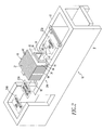
- a single pole circuit breaker 8 includes a molded housing 10 having a molded base 12 with first and second openings 14,16 molded therein for holding an upper slot motor assembly 18.
- a single pole circuit breaker 8 is shown, the invention is applicable to a wide range of electrical switching apparatus having a wide range of phase or pole counts.
- the circuit breaker 8 includes a cover (not shown), separable contacts 21A, an operating mechanism 22A, an arc chamber 23A, a trip mechanism 24A, and a slot motor assembly 26A disposed about such separable contacts.
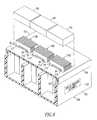
- the three-pole circuit breaker 19 of Figure 8 includes a cover 20, separable contacts 21, an operating mechanism 22 coupled to the separable contacts 21 and structured to move such contacts between an open position (not shown) and a closed position, a trip mechanism 24 structured to actuate the operating mechanism 22 to trip open the separable contacts 21, a slot motor assembly 26 disposed about the separable contacts 21, and a base 28.
- the slot motor assembly 26 includes an upper slot motor assembly 156A and a lower slot motor assembly 156B.
- this circuit breaker 19 similar to the circuit breaker 8 of Figure 2, incorporates the slot motor assembly 26 within the circuit breaker base 28.
- the upper slot motor assembly 18 is a rigid magnetic member 31 having a general U-shape (e.g. , made from a plurality of laminations stacked together; made from a solid machined or cast piece), with a bight portion 32, a first leg 34, a second leg 36, and a gap 38 between the first and second legs 34,36.
- the first leg 34 engages the base 12 at the first opening 14 and the second leg 36 engages the base 12 at the second opening 16.
- the member 31 includes a plurality of laminated U-shaped plates 40 (e.g.
- the magnetic member 31 is preferably installed in the circuit breaker housing 10 after assembly of the trip mechanism 24A and the operating mechanism 22A in the housing 10.
- each of the laminated U-shaped plates 40 includes a bight portion 44, a pair of legs 46,48, and a gap 50 between the pair of legs 46,48.
- the U-shaped holder 42 of Figure 4 includes a bight portion 52 engaging the bight portion 44 of each of the laminated U-shaped plates 40 and a pair of legs 54,56 engaging the pair of legs 46,48, respectively, of each of the laminated U-shaped plates 40.
- the laminated U-shaped plates 40 include a first laminated U-shaped plate 40A, a plurality of second or central laminated U-shaped plates 40B and a third laminated U-shaped plate 40C.
- the U-shaped holder 42 further includes a first U-shaped edge 58 engaging the first laminated U-shaped plate 40A and a second U-shaped edge 60 engaging the third laminated U-shaped plate 40C.
- the second laminated U-shaped plates 40B are laminated between the first and third laminated U-shaped plates 40A,40C.
- a sufficient count of the plates 40A,40B,40C is employed such that the combination of these plates is compressively held between the U-shaped edges 58,60.
- a suitable minimal clearance is provided between the legs 54,56 and the respective openings 14,16, in order to minimize flexing of the housing base 12.
- the laminated U-shaped steel plates 40A,40B,40C and the U-shaped holder 42 form the magnetic member 31 of Figure 2.
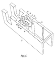
- the housing base 12 of Figure 5 includes a plurality of first interior walls 62',64,66 and a first exterior wall 68, which define the first opening 14, and a plurality of second interior walls 70,72,74 and a second exterior wall 76, which define the second opening 16.
- the first leg 34 and the second leg 36 of the magnetic member 31 of Figure 2 engage the first interior walls 62,64,66 and the second interior walls 70,72,74, in order to reinforce and add rigidity to the first exterior wall 68 and the second exterior wall 76, respectively.
- the first and second exterior walls 68,76 have a first thickness 78.
- the first and second legs 34,36 of the magnetic member 31 (and the openings 14,16) have a second thickness 80 (shown in Figures 3 and 5), which is greater than the first thickness 78.
- the first interior walls 62,64,66 and the second interior walls 70,72,74 in combination with the first leg 34 and the second leg 36 limit motion of the first exterior wall 68 and the second exterior wall 76, respectively, during interruption of a power circuit (not shown) (e.g. , when the separable contacts 21A of Figure 2 move from the closed position to the open position in response to the trip mechanism 24A).
- first and second legs 34,36 provide a continuous bridge between the first and second interior walls 62,64,66 and 70,72,74 and the first and second exterior walls 68 and 76, respectively.
- a third thickness 82 of the interior walls, such as 64,72, is smaller than the first exterior wall thickness 78.
- Non-limiting examples of the thicknesses 78, 80 and 82 are 0.200", 0.250" and 0.060" (minimum), respectively.
- the second thickness 80 of the magnetic member legs may be less than the first thickness 78 of the exterior walls.
- Each of the first and second openings 14,16 of Figure 5 has four sides 84,86,88,90.
- the three first interior walls 62,64,66 and the interior surface of the first exterior wall 68 define the four sides of the first opening 14.
- the three second interior walls 70,72,74 and the interior surface of the second exterior wall 76 define the four sides of the second opening 16.
- the first and second legs 34,36 of the magnetic member 31 of Figure 2 include four sides 92,94,96,98 (generally shown in Figure 2, with side 94 shown in Figure 3), which engage the four sides 84,86,88,90 of the first and second openings 14,16 (as shown with the opening 14 of Figure 5), in order to reinforce and add rigidity to the first and second exterior walls 68,76, respectively.
- a three-phase circuit breaker molded housing 100 includes a molded base 102 and a molded cover 104 having three cover portions 106,108,110 (shown exploded for convenience of illustration).
- both the base 102 and the cover 104 have six openings 111,112,113,114,115,116 (as shown only with the cover 104) molded therein for holding three rigid magnetic members 118A,118B,118C ( e.g., three of the rigid magnetic members 31 of Figure 2).
- the legs 34,36 of the rigid magnetic member 118A engage the molded cover 104 at the openings 111,112, respectively.
- the legs 34,36 of the rigid magnetic member 118B engage the molded cover 104 at the openings 113,114, and the legs 34,36 of the rigid magnetic member 118C engage the molded cover 104 at the openings 115,116, respectively.
- the rigid magnetic members 118A,118B,118C are installed after assembly of circuit breaker assembly 120 (as shown in block form in hidden line drawing) (including, e.g. , separable contacts, operating mechanism, trip mechanism, lower slot motor assembly, arc chamber) is complete.
- This adds rigidity to the entire circuit breaker molded housing 100 ( e.g. , the base 102 and the cover 104) and enables the exterior case walls 122,124 to withstand relatively greater pressure forces.
- Another advantage of this embodiment is that it is possible to readily change from a standard performance circuit breaker ( e.g., without a slot motor) to a relatively high performance circuit breaker ( e.g. , with a slot motor), thereby, eliminating different manufacturing styles.
- FIG. 7 shows another three-phase circuit breaker molded housing 126, with the molded cover (not shown) removed for convenience of illustration.
- This housing 126 includes the molded base 28, which is similar to the molded base 102 of Figure 6, having six openings 131,132,133,134,135,136 for holding three rigid magnetic members 138A,138B,138C ( e.g. , three of the rigid magnetic members 31 of Figure 2).
- the legs 34,36 of the rigid magnetic member 138A engage the molded base 28 at the openings 131,132, respectively.
- the legs 34,36 of the rigid magnetic member 138B engage the molded base 28 at the openings 133,134
- the legs 34,36 of the rigid magnetic member 138C engage the molded base 28 at the openings 135,136, respectively.
- the members 138A,138C add rigidity to the exterior walls 140,142
- the members 138A,138B,138C also add rigidity to the interior walls 144,146.
- the circuit breaker 19 includes a load terminal 150 and a line terminal 152. There is shown a plasma arc acceleration chamber 154 comprising the slot motor assembly 26 and an arc extinguisher assembly 158. Also shown is a contact assembly 160, the operating mechanism 22, arid the trip mechanism 24. Although not viewable in Figure 8, each phase of the three-phase circuit breaker 19 has its own load terminal 150, line terminal 152, plasma arc acceleration chamber 154, slot motor assembly 26, arc extinguisher assembly 158, and contact assembly 160.
- Each slot motor assembly 26 includes a separate first or upper slot motor portion or assembly 156A, which is disposed proximate or above the first or movable contact 180, and a second or lower slot motor portion or assembly 156B, which is disposed proximate or below the second or fixed contact 184.
- the upper slot motor assembly 156A includes a plurality of plates 168 and is structurally and functionally similar to the magnetic member 31 of Figure 2. Similar to that magnetic member, the first and second legs 186,187 (only leg 186 is shown in Figure 8) of the upper slot motor assembly 156A engage the base 28 at or within two corresponding openings 131,132 (only opening 131 with interior walls 62' and 66' is shown in Figure 8).
- the lower slot motor assembly 156B includes a lower slot motor assembly housing 170 within which are stacked side-by-side lower slot motor assembly plates 172 composed of magnetic material.
- the lower slot motor assembly 156B is structurally and functionally similar to that described in U.S. Patent Nos. 5,910,760 and 6,452,470, which are incorporated herein by reference.
- the plates 168 and 172 form an essentially closed electromagnetic path in the vicinity of movable contact 180 and stationary contact 184.
- electrical current continues to flow in a movable contact arm 178 and through an electrical arc created between contacts 180 and 184.
- This current induces a magnetic field into the closed magnetic loop provided by upper plates 168 and lower plates 172 of upper slot motor assembly 156A and lower slot motor assembly 156B, respectively.
- This magnetic field electromagnetically interacts with the current in such a manner as to accelerate the movement of the movable contact arm 178 in the opening direction whereby contacts 180 and 184 are more rapidly separated.
- the higher the magnitude of the electrical current flowing in the arc the stronger the magnetic interaction and the more quickly contacts 180 and 184 separate.
- the rigid member 31 has a general U-shape, a wide range of shapes and sizes may be employed.
- the U-shape may have square or rounded comers.
- the legs 34,36 are preferably parallel, those may be angled outward or inward to the extent that the openings 14,16 are suitably modified to receive the legs.
Landscapes
- Physics & Mathematics (AREA)
- Electromagnetism (AREA)
- Breakers (AREA)
Abstract
Description
- 1
- housing assembly
- 2
- plates
- 3
- bight portion
- 4
- leg
- 5
- leg
- 8
- circuit breaker
- 10
- circuit breaker housing
- 12
- base
- 14
- opening
- 16
- opening
- 18
- upper slot motor assembly
- 19
- circuit breaker
- 20
- cover
- 21
- separable contacts
- 21A
- separable contacts
- 22
- operating mechanism
- 22A
- operating mechanism
- 23A
- arc chamber
- 24
- trip mechanism
- 24A
- trip mechanism
- 26
- slot motor assembly
- 26A
- slot motor assembly
- 28
- base
- 31
- rigid magnetic member
- 32
- bight portion
- 34
- first leg
- 36
- second leg
- 38
- gap
- 40
- plurality of laminated U-shaped steel plates
- 40A
- first laminated U-shaped plate
- 40B
- plurality of second laminated U-shaped plates
- 40C
- third laminated U-shaped plate
- 42
- U-shaped holder
- 44
- bight portion
- 46
- leg
- 48
- leg
- 50
- gap
- 52
- bight portion
- 54
- leg
- 56
- leg
- 58
- first U-shaped edge
- 60
- second U-shaped edge
- 62
- first interior wall
- 62'
- first interior wall
- 64
- first interior wall
- 66
- first interior wall
- 66'
- first interior wall
- 68
- first exterior wall
- 70
- second interior wall
- 72
- second interior wall
- 74
- second interior wall
- 76
- second exterior wall
- 78
- first thickness
- 80
- second thickness
- 82
- third thickness
- 84
- side
- 86
- side
- 88
- side
- 90
- side
- 92
- side
- 94
- side
- 96
- side
- 98
- side
- 100
- three-phase circuit breaker molded housing
- 102
- molded base
- 104
- molded cover
- 106
- cover portion
- 108
- cover portion
- 110
- cover portion
- 111
- opening
- 112
- opening
- 113
- opening
- 114
- opening
- 115
- opening
- 116
- opening
- 118A
- rigid magnetic member
- 118B
- rigid magnetic member
- 118C
- rigid magnetic member
- 120
- circuit breaker assembly
- 122
- exterior case wall
- 124
- exterior case wall
- 126
- three-phase circuit breaker molded housing
- 131
- opening
- 132
- opening
- 133
- opening
- 134
- opening
- 135
- opening
- 136
- opening
- 138A
- rigid magnetic member
- 138B
- rigid magnetic member
- 138C
- rigid magnetic member
- 140
- exterior wall
- 142
- exterior wall
- 144
- interior wall
- 146
- interior wall
- 150
- load terminal
- 152
- line terminal
- 154
- plasma arc acceleration chamber
- 156A
- separate upper slot motor assembly
- 156B
- separate lower slot motor assembly
- 158
- arc extinguisher assembly
- 160
- contact assembly
- 168
- stacked side-by-side U-shaped upper slot motor assembly plates
- 170
- lower slot motor assembly housing
- 172
- stacked side-by-side lower slot motor assembly plates
- 178
- movable contact arm
- 180
- contact
- 184
- contact
- 186
- leg
- 187
- leg
- 190
- pivot pin
- 192
- crossbar assembly
Claims (24)
- An upper slot motor assembly (18) for a circuit breaker slot motor assembly (26A), said upper slot motor assembly (18) comprising:a circuit breaker housing (10) including a circuit breaker base (12) having a first opening (14) and a second opening (16); anda rigid magnetic member (31) having a bight portion (32), a first leg (34), and a second leg (36), the first leg (34) of said rigid magnetic member (31) engaging the circuit breaker base (12) of said circuit breaker housing (10) at said first opening (14), the second leg (36) of said rigid magnetic member (31) engaging the circuit breaker base (12) of said circuit breaker housing (10) at said second opening (16).
- The upper slot motor assembly (18) of Claim 1 wherein said rigid magnetic member (31) comprises a plurality of laminated U-shaped plates (40) resting in a U-shaped holder (42).
- The upper slot motor assembly (18) of Claim 2 wherein said U-shaped holder (42) engages the circuit breaker base (12) of said circuit breaker housing (10) proximate the first and second opening (14,16) of said circuit breaker base (12).
- The upper slot motor assembly (18) of Claim 2 wherein each of said laminated U-shaped plates (40) includes a bight portion (44), and a pair of legs (46,48); and wherein said U-shaped holder (42) includes a bight portion (52) engaging the bight portion (44) of each of said laminated U-shaped plates (40) and a pair of legs (54,56) engaging the pair of legs (46,48) of each of said laminated U-shaped plates (40).
- The upper slot motor assembly (18) of Claim 4 wherein said laminated U-shaped plates (40) include a first laminated U-shaped plate (40A), a plurality of second laminated U-shaped plates (40B) and a third laminated U-shaped plate (40C); wherein said U-shaped holder (42) further includes a first U-shaped edge (58) engaging the first laminated U-shaped plate (40A) and a second U-shaped edge (60) engaging the third laminated U-shaped plate (40C); and wherein said second laminated U-shaped plates (40B) are laminated between said first and third laminated U-shaped plates (40A,40C).
- The upper slot motor assembly (18) of Claim 5 wherein said first, second and third laminated U-shaped plates (40A,40B,40C) are made of steel.
- The upper slot motor assembly (18) of Claim 1 wherein the circuit breaker base (12) of said circuit breaker housing (10) includes a plurality of first interior walls (62,64,66) and a first exterior wall (68), which define the first opening (14) of said circuit breaker base (12), and a plurality of second interior walls (70,72,74) and a second exterior wall (76), which define the second opening (16) of said circuit breaker base (12); and wherein the first and second legs (34,36) of said rigid magnetic member (31) engage said first and second interior walls (62,64,66;70,72,74), in order to reinforce the first and second exterior walls (68,76), respectively, of said circuit breaker base (12).
- The upper slot motor assembly (18) of Claim 7 wherein the first and second exterior walls (68,76) have a first thickness (78); and wherein the first and second legs (34,36) of said rigid magnetic member (31) have a second thickness (80), which is greater than said first thickness (78).
- The upper slot motor assembly (18) of Claim 8 wherein the first and second interior walls (64;72) have a third thickness (82), which is less than said first thickness (78).
- The upper slot motor assembly (18) of Claim 1 wherein said rigid magnetic member (31) is made of steel.
- The upper slot motor assembly (18) of Claim 1 wherein the circuit breaker base (12) of said circuit breaker housing (10) is a molded circuit breaker base (12) having the first and second openings (14,16) molded therein.
- The upper slot motor assembly (18) of Claim 1 wherein the circuit breaker base (12) of said circuit breaker housing (10) is a molded circuit breaker base (12); wherein said circuit breaker housing (10) further includes a molded cover (104) having a third opening (111) and a fourth opening (112); and wherein the first leg (34) of said rigid magnetic member (118A) engages the molded cover (104) of said circuit breaker housing (100) at said third opening (111), and the second leg (36) of said rigid magnetic member (118A) engages the molded cover (104) of said circuit breaker housing (100) at said fourth opening (112).
- A circuit breaker (19) comprising:a housing (20,28) including a first opening (131) and a second opening (132);at least one pair of separable contacts (21) including a stationary contact (184) and a movable contact (180) disposed in said housing (20,28);an operating mechanism (22) disposed in said housing (20,28) and coupled to said separable contacts (21), said operating mechanism (22) being structured to move said separable contacts (21) between an open position and a closed position;a trip mechanism (24) disposed in said housing (20,28) and coupled to said operating mechanism (22), said trip mechanism (24) being structured to actuate said operating mechanism (22) to open said separable contacts (21); anda slot motor assembly (26) disposed about said separable contacts (21), said slot motor assembly (26) having an upper slot motor assembly (156A) and a lower slot motor assembly (156B), said lower slot motor assembly (156B) being disposed below said stationary contact (184), said upper slot motor assembly (156A) being disposed above said movable contact (180), said upper slot motor assembly (156A) comprising a rigid magnetic member (31) having a bight portion (32), a first leg (34), and a second leg (36), the first leg (34) of said rigid magnetic member (31) engaging said housing (20,28) within said first opening (131), the second leg (36) of said rigid magnetic member (31) engaging said housing (20,28) within said second opening (132).
- The circuit breaker (19) of Claim 13 wherein said rigid magnetic member (31) comprises a plurality of laminated U-shaped steel plates (40) resting in a U-shaped holder (42).
- The circuit breaker (19) of Claim 13 wherein said housing (20,28) further includes a plurality of first interior walls (62,64,66) and a first exterior wall (68), which define the first opening (14), and a plurality of second interior walls (70,72,74) and a second exterior wall (76), which define the second opening (16); and wherein the first and second legs (34,36) of said rigid magnetic member (31) engage said first and second interior walls (62,64,66;70,72,74), in order to reinforce the first and second exterior walls (68,76), respectively.
- The circuit breaker (19) of Claim 15 wherein the first and second exterior walls (68,76) have a first thickness (78); and wherein the first and second legs (34,36) of said rigid magnetic member (31) have a second thickness (80), which is greater than said first thickness (78).
- The circuit breaker (19) of Claim 15 wherein the first and second interior walls (62,64,66;70,72,74) of said housing (20,28) in combination with said first and second legs (34,36) limit motion of the first and second exterior walls (68,76), respectively, of said housing (20,28) during interruption of a power circuit when said separable contacts (160) move from the closed position to the open position in response to said trip mechanism (24).
- The circuit breaker (19) of Claim 17 wherein the first and second interior walls (62,64,66;70,72,74) of said housing (20,28) in combination with said first and second legs (34,36) enable the first and second exterior walls (68,76), respectively, of said housing (20,28) to withstand pressure within said housing (20,28) during interruption of said power circuit.
- The circuit breaker (19) of Claim 17 wherein said first and second legs (34,36) provide a continuous bridge between the first and second interior walls (62,64,66;70,72,74) of said housing (20,28) and the first and second exterior walls (68,76), respectively, of said housing (10).
- The circuit breaker (19) of Claim 13 wherein said housing (20,28) further includes a molded base (28) having the first and second openings (131,132) molded therein.
- The circuit breaker (19) of Claim 13 wherein said housing (20,28) further includes a molded base (102) and a molded cover (104) having the first and second openings (111,112,113,114,115,116) molded therein.
- The circuit breaker (19) of Claim 13 wherein said rigid magnetic member (31) is installed in said circuit breaker (19) after assembly of said trip mechanism (24) and said operating mechanism (22) in said housing (20,28).
- An electrical switching apparatus (19) comprising:a housing (20,28) including a first opening (131) and a second opening (132);separable contacts (21) including a first contact (180) and a second contact (184) disposed in said housing (20,28);an operating mechanism (22) disposed in said housing (20,28) and coupled to said separable contacts (21), said operating mechanism (22) being structured to move said separable contacts (21) between an open position and a closed position;a trip mechanism (24) disposed in said housing (20,28) and cooperating with said operating mechanism (22) to trip open said separable contacts (21); anda slot motor assembly (26) disposed about said separable contacts (21), said slot motor assembly (26) having a first slot motor portion (156A) and a second slot motor portion (156B), said first slot motor portion being disposed proximate said first contact (180), said second slot motor portion (156B) being disposed proximate said second contact (184), said first slot motor portion (156A) comprising a rigid magnetic member (31) having a bight portion (32), a first leg (34), and a second leg (36), the first leg (34) of said rigid magnetic member (31) engaging said housing (20,28) at said first opening (131), the second leg (36) of said rigid magnetic member (31) engaging said housing (20,28) at said second opening (132).
- The electrical switching apparatus (19) of Claim 23 wherein said first (131;14) and second (132;16) openings have four sides (84,86,88,90); wherein said housing (20,28) further includes three first interior walls (62,64,66) and a first exterior wall (68), which define the four sides (84,86,88,90) of the first opening (14), and three second interior walls (70,72,74) and a second exterior wall (76), which define the four sides (84,86,88,90) of the second opening (16); and wherein the first and second legs (34,36) of said rigid magnetic member (31) include four sides (92,94,96,98), which engage the four sides (84,86,88,90) of said first and second openings (14,16), in order to reinforce the first and second exterior walls (68,76), respectively.
Applications Claiming Priority (2)
| Application Number | Priority Date | Filing Date | Title |
|---|---|---|---|
| US733145 | 2003-12-11 | ||
| US10/733,145 US6970059B2 (en) | 2003-12-11 | 2003-12-11 | Slot motor including legs engaging openings of circuit breaker housing and electrical switching apparatus employing the same |
Publications (2)
| Publication Number | Publication Date |
|---|---|
| EP1542254A2 true EP1542254A2 (en) | 2005-06-15 |
| EP1542254A3 EP1542254A3 (en) | 2007-12-19 |
Family
ID=34523064
Family Applications (1)
| Application Number | Title | Priority Date | Filing Date |
|---|---|---|---|
| EP04029365A Withdrawn EP1542254A3 (en) | 2003-12-11 | 2004-12-10 | Slot motor including legs engaging openings of circuit breaker housing and electrical switching apparatus employing the same |
Country Status (4)
| Country | Link |
|---|---|
| US (1) | US6970059B2 (en) |
| EP (1) | EP1542254A3 (en) |
| AU (1) | AU2004237833B2 (en) |
| CA (1) | CA2490035A1 (en) |
Cited By (1)
| Publication number | Priority date | Publication date | Assignee | Title |
|---|---|---|---|---|
| EP2830076A1 (en) * | 2013-07-26 | 2015-01-28 | Siemens Aktiengesellschaft | Switching device |
Families Citing this family (9)
| Publication number | Priority date | Publication date | Assignee | Title |
|---|---|---|---|---|
| US6970059B2 (en) * | 2003-12-11 | 2005-11-29 | Eaton Corporation | Slot motor including legs engaging openings of circuit breaker housing and electrical switching apparatus employing the same |
| US7348514B2 (en) * | 2006-04-12 | 2008-03-25 | Eaton Corporation | Slot motor and circuit breaker including the same |
| US7358837B2 (en) * | 2006-04-12 | 2008-04-15 | Eaton Corporation | Electrical switching apparatus and circuit breaker including a molded enclosure and machine screws reinforcing the same |
| US7532097B2 (en) * | 2007-02-12 | 2009-05-12 | Eaton Corporation | Slot motor housing and circuit interrupter including the same |
| US20140253264A1 (en) * | 2013-03-07 | 2014-09-11 | Eaton Corporation | Circuit breaker slot motor |
| US9767980B2 (en) | 2015-10-28 | 2017-09-19 | Eaton Corporation | Electrical switching apparatus, and slot motor and enclosure therefor |
| US9653237B1 (en) | 2015-12-03 | 2017-05-16 | Eaton Corporation | Electrical switching apparatus and slot motor therefor |
| US10128069B1 (en) | 2017-07-18 | 2018-11-13 | Eaton Intelligent Power Limited | Electrical switching apparatus and debris barrier therefor |
| US11183817B2 (en) | 2019-05-22 | 2021-11-23 | Eaton Intelligent Power Limited | Arc mitigation devices and systems for panelboard applications |
Family Cites Families (14)
| Publication number | Priority date | Publication date | Assignee | Title |
|---|---|---|---|---|
| US3815059A (en) | 1972-12-01 | 1974-06-04 | Westinghouse Electric Corp | Circuit interrupter comprising electromagnetic opening means |
| IT1129691B (en) | 1980-01-31 | 1986-06-11 | Elettromeccanica Spa Cge Comp | RAPID EXTINGUISHING COMPLEX OF THE ELECTRIC ARC IN INTERRUPTION DEVICES SUCH AS ELECTRIC SWITCHES |
| US4549153A (en) | 1983-09-02 | 1985-10-22 | Eaton Corporation | Residential circuit breaker with slot motor |
| US4546336A (en) | 1983-09-02 | 1985-10-08 | Eaton Corporation | Residential circuit breaker with combination slot motor and arc chute |
| US4546337A (en) | 1983-09-02 | 1985-10-08 | Eaton Corporation | Residential circuit breaker with one piece slot motor |
| US4743720A (en) * | 1985-11-25 | 1988-05-10 | Matsushita Electric Works, Ltd. | Current limiting circuit interrupter |
| US4963849A (en) * | 1989-04-28 | 1990-10-16 | General Electric Company | Compact current limiting circuit breaker |
| US4970482A (en) | 1990-01-29 | 1990-11-13 | General Electric Company | Current limiting circuit breaker compact arc chute configuration |
| US5258733A (en) * | 1992-08-06 | 1993-11-02 | Eaton Corporation | Molded case circuit breaker having improved trip unit |
| US5694098A (en) * | 1996-05-20 | 1997-12-02 | Eaton Corporation | Rate of current rise sensitive slot motor and switching apparatus having current limiting contact arrangement incorporating said slot motor |
| US5927484A (en) | 1997-05-28 | 1999-07-27 | Eaton Corporation | Circuit breaker with welded contact interlock, gas sealing cam rider and double rate spring |
| AU6588800A (en) | 1999-08-30 | 2001-03-26 | Eaton Corporation | Circuit interrupter with crossbar having improved barrier protection |
| US6281459B1 (en) * | 2000-04-21 | 2001-08-28 | Eaton Corporation | Circuit interrupter having an improved slot motor assembly |
| US6970059B2 (en) * | 2003-12-11 | 2005-11-29 | Eaton Corporation | Slot motor including legs engaging openings of circuit breaker housing and electrical switching apparatus employing the same |
-
2003
- 2003-12-11 US US10/733,145 patent/US6970059B2/en not_active Expired - Fee Related
-
2004
- 2004-12-09 AU AU2004237833A patent/AU2004237833B2/en not_active Ceased
- 2004-12-10 EP EP04029365A patent/EP1542254A3/en not_active Withdrawn
- 2004-12-10 CA CA002490035A patent/CA2490035A1/en not_active Abandoned
Cited By (1)
| Publication number | Priority date | Publication date | Assignee | Title |
|---|---|---|---|---|
| EP2830076A1 (en) * | 2013-07-26 | 2015-01-28 | Siemens Aktiengesellschaft | Switching device |
Also Published As
| Publication number | Publication date |
|---|---|
| AU2004237833A1 (en) | 2005-06-30 |
| AU2004237833B2 (en) | 2008-10-23 |
| US6970059B2 (en) | 2005-11-29 |
| EP1542254A3 (en) | 2007-12-19 |
| US20050128033A1 (en) | 2005-06-16 |
| CA2490035A1 (en) | 2005-06-11 |
Similar Documents
| Publication | Publication Date | Title |
|---|---|---|
| EP1906430B1 (en) | Electrical switching apparatus including a split core slot motor and method of installing a slot motor assembly in a circuit interrupter | |
| US20020056705A1 (en) | Current-limiting contact arrangement | |
| EP3384512B1 (en) | Electrical switching apparatus and slot motor therefor | |
| EP1956624B1 (en) | Slot motor housing and circuit interrupter including the same | |
| US6970059B2 (en) | Slot motor including legs engaging openings of circuit breaker housing and electrical switching apparatus employing the same | |
| EP2005459B1 (en) | Slot motor and circuit breaker including the same | |
| EP4120304B1 (en) | Air circuit breaker | |
| EP0105381B1 (en) | Circuit breaker | |
| MXPA97007781A (en) | Electrical current switch apparatus with arc tornad extinguishing mechanism | |
| EP4120306B1 (en) | Arc extinguishing unit and air circuit breaker comprising same | |
| US12198879B2 (en) | Air circuit breaker | |
| US6831536B1 (en) | Circuit breaker slot motor having a stepped out portion | |
| US7439469B2 (en) | Electric switching device comprising an arc-quenching unit | |
| JP6044927B2 (en) | DC switch and DC circuit breaker | |
| JPH0696656A (en) | Three-pole circuit breaker | |
| JP3267660B2 (en) | Electromagnetic contactor |
Legal Events
| Date | Code | Title | Description |
|---|---|---|---|
| PUAI | Public reference made under article 153(3) epc to a published international application that has entered the european phase |
Free format text: ORIGINAL CODE: 0009012 |
|
| AK | Designated contracting states |
Kind code of ref document: A2 Designated state(s): AT BE BG CH CY CZ DE DK EE ES FI FR GB GR HU IE IS IT LI LT LU MC NL PL PT RO SE SI SK TR |
|
| AX | Request for extension of the european patent |
Extension state: AL BA HR LV MK YU |
|
| PUAL | Search report despatched |
Free format text: ORIGINAL CODE: 0009013 |
|
| AK | Designated contracting states |
Kind code of ref document: A3 Designated state(s): AT BE BG CH CY CZ DE DK EE ES FI FR GB GR HU IE IS IT LI LT LU MC NL PL PT RO SE SI SK TR |
|
| AX | Request for extension of the european patent |
Extension state: AL BA HR LV MK YU |
|
| 17P | Request for examination filed |
Effective date: 20080402 |
|
| AKX | Designation fees paid |
Designated state(s): DE FR GB IT NL |
|
| STAA | Information on the status of an ep patent application or granted ep patent |
Free format text: STATUS: THE APPLICATION IS DEEMED TO BE WITHDRAWN |
|
| 18D | Application deemed to be withdrawn |
Effective date: 20100701 |