TECHNICAL FIELD
The present invention relates to a recording medium made
of a photosensitive material, so-called a holographic memory,
and especially the present invention relates to a method for
holographic recording and reproducing and an optical information
recording and reproducing apparatus using the holographic
memory.
BACKGROUND ART
A volume holographic recording system is known as a digital
data recording system using a principle of holography. This
system is characterized in that information is recorded on a
recording medium made of a photosensitive material such as a
photorefractive material as a variation of a refractive index
of the medium.
One of conventional methods for holographic recording and
reproducing uses the Fourier transform for recording and
reproducing.
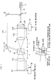
Referring to Fig. 1, in the conventional 4f series of
holographic recording and reproducing apparatus, a beam splitter
13 splits a laser beam 12 generated from a laser light source
11 into light beams 12a and 12b. A beam expander BX expands the
diameter of the light beam 12a. Then, the light beam 12a being
a parallel pencil is applied to a spatial light modulator SLM
such as the panel of a transmissive TFT liquid crystal display
(LCD) and the like. The spatial light modulator SLM receives
information to be recorded as electronic signals encoded by an
encoder, to form two-dimensional data, that is, a light and dark
dot pattern and the like corresponding to the information formed
on a plane. When the light beam 12a passes through the spatial
light modulator SLM, the spatial light modulator SLM optically
modulates the light beam 12a to a signal beam including a data
signal component. Since the signal beam 12a including a dot
pattern signal component passes through a Fourier transform lens
16 disposed at a distance of a focal length f from the spatial
light modulator SLM, the dot pattern signal component is
transformed to a Fourier component and converged into a recording
medium 10. A light beam 12b split by the beam splitter 13 is
led into the recording medium 10 with mirrors 18 and 19. The
light beam 12b as a reference beam intersects the light path of
the signal beam 12a inside the recording medium 10. The
interference of the light beam 12b and the signal beam 12a creates
a light interference pattern. The whole light interference
pattern is recorded as a diffraction grating such as the variation
of a refractive index (a refractive index grating) and the like.
As described above, the coherent parallel pencil is
diffracted by the dot pattern data, and forms an optical image
with the Fourier transform lens. The distribution of the image
on the focal plane of the Fourier transform lens, namely on a
Fourier plane, interferes with the coherent reference beam. Then,
interference fringes are recorded on the recording medium in the
vicinity of a focal point. After finishing the record of a first
page, the turnable mirror is turned by predetermined degrees and
moved in parallel, in order to vary the incident angle of the
reference beam 12b into the recording medium 10. Then, a second
page is recorded following the same procedure as above. Multiple
angle recording is carried out in this way.
On the other hand, the inverse Fourier transform is used
in reproducing a dot pattern image. In reproducing the recorded
information, as shown in Fig. 1, the spatial light modulator SLM,
for example, intercepts the light path of the signal beam 12a,
so that only the reference beam 12b is incident on the recording
medium 10. The position and the angle of the mirror are so
controlled by varying the combination of rotation and movement
thereof, that the incident angle of the reference beam 12b becomes
same as that in recording of the page to be reproduced. A
reproduced beam which reproduces the recorded signal beam appears
on the opposite side of the recording medium 10, on which the
recorded signal beam 12a is incident. Leading the reproduced
beam to an inverse Fourier transform lens 16a and performing the
inverse Fourier transform reproduces the dot pattern signals.
The dot pattern signals are received by a photo detector 20 such
as a charge-coupled device CCD and the like disposed in the
position of a focal length of the lens 16a, and re-converted into
the electrical digital data signals. Then, the digital data
signals are sent to a decoder to decode original data.
Referring to Fig. 1, the multiple images are conventionally
recorded in a few millimeters volume of the recording medium with
the use of multiple angles and multiple wavelengths, in order
to record the information in some volume thereof in high density.
Accordingly, a wide field and long range coherent for the signal
beam and the reference beam is necessary to secure the selectivity
of an angle and a wavelength. Therefore, the intensity of the
light beam per the amount of light used for recording is decreased.
Multiple recording is necessary for high density recording, so
that the recording medium which has a large erasure time constant
and is easy to perform the multiple recording is required.
The conventional holographic recording and reproducing
apparatus requires high spec two lenses, which are the Fourier
transform lens and the inverse Fourier transform lens. The
apparatus also needs to be provided with a high accuracy paging
control mechanism for controlling the reference beam in recording
and reproducing the information. Therefore, there is a
disadvantage that the apparatus becomes large in size.
DISCLOSURE OF INVENTION
An object of the present invention is to provide a method
for holographic recording and reproducing and an apparatus
therefor which can decrease in size and record a hologram on a
holographic recording medium.
According to the present invention, there is provided a
method for holographic recording and reproducing comprising a
recording process and a reproducing process,
The signal beam is a light beam resulted from such operation
that a coherent reference beam spatially modulated in accordance
with information to be recorded, which comprises a 0th-order beam
having a wavefront having the same shape wherever regardless
spatial modulation; and a diffraction beam subjected to the
spatial modulation. Thus, the present invention uses the
0th-order beam of the signal beam as reference light for a
holographic recording.
In recording, the recording medium is illuminated with the
signal beam to generate optical interference fringe patterns
caused by the 0th-order beam and the diffraction beam at the path
of the signal beam to record the refractive index grating in the
recording medium correspondingly to the interference fringe
patterns.
In reproducing, the recording medium particularly the
refractive index grating therein is illuminated with a signal
beam which is not spatially modulated i.e., non-modulated
reference beam with the same positional and angular condition
of the signal beam used in the recording. Since the non-modulated
reference beam includes the 0th-order beam as a major components,
the illumination of the non-modulated reference beam to the
refractive index grating of the recording medium generates a
reproduced wave having a wavefront as the same as that of the
signal beam used in the recording.
In a detection of the reproduced wave, the reproduced waves
emitted from the refractive index grating in the recording medium
overlap with the non-modulated reference beam used for the
reproducing. Removing or reducing the non-modulated reference
beam used for the reproducing facilitates to detect the
reproduced wave easily and reproduce the recorded information
electrically.
According to the present invention, there is also provided
a recording medium made of a photosensitive material capable of
being recorded by illumination with a coherent light beam, the
recording medium comprising an incident-light-processing area
provided in said recording medium on an opposite side of an
entrance surface of the recording medium on which the light beam
is incident, the incident-light-processing area separating a
0th-order beam and a diffraction beam of the light beam from each
other to return a part of the incident beam to the inside of said
recording medium.
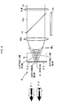
To removing or reduce the non-modulated reference beam used
for the reproducing, as shown in Fig. 2, the recording medium
10 is provided with an incident-light-processing area R which
comprises a 0th-order-beam-processing area R1 processing the
0th-order beam of the signal beam and the non-modulated reference
beam and a diffraction-beam-processing area R2 processing the
diffraction beam of the signal beam in such a manner that the
incident-light-processing area is disposed at a beam waist of
the non-modulated reference beam which is converged by a
condenser lens to focus on the opposite side of an entrance surface
of the recording medium on which the beam is incident.
There are considered the use of a phase conjugate wave as
one of methods for a holographic recording and reproducing system
in the recording and reproducing method. The reproducing method
with the phase conjugate beam generally requires the identical
reference beam in both the recording and reproducing similarly
to the other methods. For example, there is a method for
recording and reproducing information in which the refractive
index grating is generated and recorded by interference in the
recording medium in such a manner that the signal beam is irradiate
to the recording medium and reflected by a mirror to generate
a phase conjugate wave back to the recording medium so that the
phase conjugate wave and the signal beam interfere each other.
In such recording and reproducing method, there are drawbacks
such as a necessity to insert and detach the reflecting mirror,
a degradation of light source with a return of the signal beam
particularly the 0th-order beam, and a large-sized device
including an optical systems to prevent the return light. In
contrast, according to the present invention, the incident-light-processing
area dissolves the problems because the
0th-order beam and the diffraction beam in the incident light
are processed individually with different processed such as a
separation to return a part of the incident beam to the inside
of the recording medium.
In addition, there is no necessity to provide respective
two optical systems for the reference beam and signal beam
differently than the conventional holographic recording and
reproducing method in the present invention. Furthermore, the
method of the present invention does not require a condenser lens
with a high performance which is used as an objective lens and
the like. Adopting this recording and reproducing method is
highly effective to simplify and miniaturize a recording and
reproducing apparatus, because of using the 0th-order beam and
the diffraction beam (spatially modulated in accordance with
information to be recorded) included in the signal beam.
According to the present invention, there is further
provided a method for holographic recording comprising the steps
of:
According to the present invention, there is still further
provided a method for holographic reproducing comprising the
steps of:
According to the present invention, moreover there is
provided a holographic recording and reproducing apparatus for
recording information as a diffraction grating area in a
recording medium, and for reproducing said recorded information
from said diffraction grating area, said holographic recording
and reproducing apparatus comprising:
According to the present invention, there is also provided
a holographic recording apparatus for recording information as
a diffraction grating area in a recording medium, comprising:
According to the present invention, there is furthermore
provided a holographic reproducing apparatus for reproducing
information recorded as a diffraction grating area in a recording
medium, the reproducing apparatus comprising:
According to the present invention, there is furthermore
provided another holographic recording and reproducing apparatus
for recording information as a diffraction grating area in a
recording medium, and for reproducing said recorded information
from said diffraction grating area, said holographic recording
and reproducing apparatus comprising:
According to the present invention, there is also provided
another holographic recording apparatus for recording
information as a diffraction grating area in a recording medium,
comprising:
According to the present invention, there is further
provided another holographic reproducing apparatus for
reproducing information recorded as a diffraction grating area
in a recording medium, the reproducing apparatus comprising:
BRIEF DESCRIPTION OF THE DRAWINGS
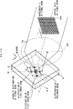
Fig. 1 is a schematic view showing the configuration of
a conventional holographic recording and reproducing system.
Fig. 2 is a schematic sectional view of a holographic
recording medium according to an embodiment of the present
invention.
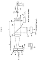
Fig. 3 is a schematic view showing the configuration of
a holographic recording and reproducing apparatus according to
an embodiment of the present invention.
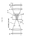
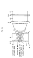
Fig. 4 is a schematic sectional view for explaining the
recording process carried out by the holographic recording and
reproducing apparatus according to the embodiment of the present
invention.
Fig. 5 is a schematic sectional view of a holographic
recording medium for use in the embodiment of the present
invention.
Fig. 6 is a schematic plan view for explaining the relation
between the holographic recording medium and a spatial light
modulator according to the embodiment of the present invention.
Fig. 7 is a schematic perspective view for explaining the
recording process carried out by the holographic recording and
reproducing apparatus according to the present invention.
Fig. 8 is a schematic sectional view for explaining the
reproducing process carried out by the holographic recording and
reproducing apparatus according to the embodiment of the present
invention.
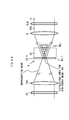
Figs. 9 and 10 are schematic sectional views for explaining
the recording process carried out by the holographic recording
and reproducing apparatus according to modified examples of the
embodiment of the present invention.
Fig. 11 is a schematic view showing the configuration of
a holographic recording and reproducing apparatus according to
another embodiment of the present invention.
Fig. 12 is a schematic sectional view for explaining the
recording process carried out by the holographic recording and
reproducing apparatus according to the embodiment of the present
invention.
Fig. 13 is a schematic sectional view of a holographic
recording medium for use in the embodiment of the present
invention.
Fig. 14 is a schematic sectional view for explaining the
reproducing process carried out by the holographic recording and
reproducing apparatus according to the embodiment of the present
invention.
Figs. 15 to 17 are schematic sectional views for explaining
the recording process carried out by the holographic recording
and reproducing apparatus according to modified examples of the
embodiment of the present invention.
Fig. 18 is a schematic view showing the configuration of
a holographic recording and reproducing apparatus according to
another embodiment of the present invention.
Fig. 19 is a schematic plan view for explaining the relation
between the holographic recording medium and a spatial light
modulator according to the embodiment of the present invention.
Fig. 20 is a schematic perspective view for explaining the
recording process carried out by the holographic recording and
reproducing apparatus according to the present invention.
Figs. 21 and 22 are schematic sectional views for
explaining the recording process carried out by the holographic
recording and reproducing apparatus according to modified
examples of the other embodiment of the present invention.
Fig. 23 is a schematic view showing the configuration of
a holographic recording and reproducing apparatus according to
another embodiment of the present invention.
Figs. 24 to 26 are schematic sectional views for explaining
the recording process carried out by the holographic recording
and reproducing apparatus according to modified examples of the
other embodiments of the present invention.
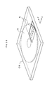
Fig. 27 is a schematic perspective view showing a device
for an incident-light-processing area of a holographic recording
and reproducing apparatus according to another embodiment of the
present invention.
Fig. 28 is a schematic perspective view showing a recording
medium cartridge of a holographic recording and reproducing
apparatus according to another embodiment of the present
invention.
DETAILED DESCRIPTION OF THE INVENTION
Embodiments of the present invention will be hereinafter
described with reference to the accompanying drawings.
The present embodiment does not use the reference beam
provided by another optical path in recording. Instead, only
the signal beam is incident on the recording medium, and a
refractive index grating generated by interference between the
0th-order beam and the diffraction beam of the signal beam is
recorded. After that, the reproduced wave is reproduced from
the refractive index grating by illuminating the refractive index
grating only with the reference beam. An incident-light-processing
area is integrally provided in the recording medium
on an opposite side of an entrance surface thereof on which the
light beam is incident. The incident-light-processing area
separates a 0th-order beam and a diffraction beam of the light
beam from each other to return a part of the incident beam to
the inside of the recording medium.
<First embodiment>
Fig. 3 shows a holographic recording and reproducing
apparatus according to an embodiment. In the apparatus, a
near-infrared laser like a DBR (Distributed Bragg Reflector)
laser with a wavelength of 850nm, for example, is used as a light
source 11. A shutter SHs, a beam expander BX, a spatial light
modulator SLM, a beam splitter 15, and a condenser lens 160 are
disposed in the optical path of a reference beam 12. The shutter
SHs, controlled by a controller 32, controls an illumination time
of the recording medium with light beam.
The beam expander BX expands the diameter of the light beam
12 passing through the shutter SHs. The light beam 12 becoming
a parallel pencil is incident on the spatial light modulator SLM.
The spatial light modulator SLM displays light and dark dot matrix
signals, in accordance with electronic data received from an
encoder 25. The electronic data is represented as a series of
a page unit corresponding to a two-dimensional page. Upon
passing through the spatial light modulator SLM on which the data
is displayed, the reference beam is optically modulated into a
signal beam 12a including the data as a dot matrix component.
The condenser lens 160 performs the Fourier transform on the dot
matrix component of the signal beam 12a passing through the beam
splitter 15, and converges it so that the signal beam 12a comes
into a focus behind a mounted recording medium 10. When the
shutter SHs is opened, the signal beam 12a or the reference beam
12 is incident on the principal surface of the recording medium
10 at a predetermined incident angle, a zero-degree for example,
due to the condenser lens 160. The beam splitter 15 is a splitting
unit to separate a reproduced wave (described later) from the
optical path of the reference beam to supply it the photo detector
20 of a photoelectric transfer device like a CCD. The spatial
light modulator SLM and the CCD 20 are disposed at the focal point
of the condenser lens 160.
In addition, the beam splitter 15 is disposed in such a
position as to be able to send the reproduced wave to the CCD
20. The CCD 20 is connected to a decoder 26. The decoder 26 is
connected to the controller 32. Taking a case where information
corresponding to the type of a photorefractive crystal is
attached to the recording medium 10 in advance, when the recording
medium 10 is mounted on a movable stage 60, which is a holding
section to move the recording medium 10, the controller 32
automatically reads the information with a proper sensor to
perform controllings of the movement of the recording medium 10
and the recording and reprocusing adapted to the recording medium
10.
Referring to Fig. 3, the recording medium 10 is integrally
provided on the opposite side of an entrance surface with an
incident-light-processing area R which includes a 0th-order-beam-processing
area R1 for passing the 0th-order beam in the
signal beam 12a and a diffraction-beam-processing area R2 for
reflecting the diffraction beam in the signal beam 12a. The
incident-light-processing area R is provided for processing the
signal beam. For example, the incident-light-processing area
R comprises an opening for passing the 0th-order beam, and the
diffraction-beam-processing area R2 for defining the opening.
The incident-light-processing area R is not limited to above,
as long as the 0th-order-beam-processing area R1 has a different
role than the diffraction-beam-processing area R2. Zeroth-order
beam absorbing material may be provided for the 0th-order-beam-processing
area R1 instead of the opening. In other
words, the 0th-order-beam-processing area R1 in the
incident-light-processing area R passes or absorbs the 0th-order
beam.
The operation in a recording process will be hereinafter
described.
The controller 32 shown in Fig. 3 controls the position
of the movable stage 60 holding the recording medium 10 so that
the objective recording medium 10 is moved to a predetermined
recording position.
Then, the recording signals are sent from the encoder 25
to the spatial light modulator SLM, and the spatial light
modulator SLM displays a specific pattern corresponding to data
to be recorded.
Then, the shutter SHs is opened, and the spatial light
modulator SLM is illuminated with a reference beam 12. A signal
beam 12a is generated in the reference beam 12 spatially modulated
by the spatial light modulator SLM on which the pattern is
displayed in accordance with information to be recorded. The
recording medium 10 is irradiated with the generated signal beam
12a to the to start the recording process.
The recording process of the refractive index grating using
the signal beam 12a (i.e., 0th-order beam and diffraction beam
therein) in the recording medium will be hereinafter described
in detail.
As shown in Fig. 4, the signal beam 12a includes a 0th-order
beam and a diffraction beam subjected to the spatial modulation.
The 0th-order beam of the signal beam 12a has a wavefront having
a constant shape without any influence from the spatial
modulation and therefore it is referred to as "hologram-reference
beam". The diffraction beam of the signal beam 12a subjected
to the spatial modulation is referred to as "hologram-signal
beam". Accordingly, the signal beam 12a comprises the
hologram-reference beam and the hologram-signal beam at least
in recording.
Since the recording medium 10 is illuminated with the
signal beam 12a, the hologram-reference beam and the
hologram-signal beam are optically interfered with each other
to create an optical interference fringe pattern P1, so that a
refractive index grating P1 is recorded in the recording medium
10 due to the photorefractive effect.
The 0th-order beam (i.e. , hologram-reference beam) of the
signal beam 12a passes through the 0th-order-beam-processing
area R1 of the incident-light-processing area R and goes out from
the opposite side of the recording medium 10, on which the signal
beam 12a is incident. The diffraction beam (i.e., hologram-signal
beam) of the signal beam 12a is reflected by the
diffraction-beam-processing area R2 of the incident-light-processing
area R back to the recording medium 10. Therefore
such diffraction beam of the signal beam 12a reflected by the
diffraction-beam-processing area R2 is referred to as
"reflected-hologram-signal beam".
The reflected-hologram-signal beam and the hologram-reference
beam are optically interfered with each other in the
recording medium 10 to create an optical interference fringe
pattern P2, so that a refractive index grating P2 is recorded
corresponding to the optical interference fringe pattern P2 in
the recording medium 10 due to the photorefractive effect.
In this way, the 0th-order beam and the diffraction beam
(i.e. , the signal beam 12a) from the spatial light modulator SLM
together with the reflected diffraction beam from the
diffraction-beam-processing area R2 create the set of the
three-dimensional interference patterns inside the recording
medium 10 in the recording. As shown in Fig. 5, the refractive
index gratings P1, P2 corresponding to optical interference
fringe patterns P1, P2 are hologram-recorded in the recording
medium 10 due to a photorefractive effect.
After recording of the recording medium 10, the shutter
SHs is closed by control of the controller 32.
When the recording is finished at the predetermined
recording position of the recording medium 10, the recording
medium 10 is forced to move (in a "y" direction of Fig. 3) for
the purpose of reaching another predetermined recording position
of the signal beam 12a with respect to the recording medium 10.
Then a next recording is carried out following the previous
procedure. The recording is sequentially carried out like this.
Fig. 6 shows the recording medium 10 and the spatial light
modulator SLM placed side by side, which are viewed on an optical
axis of the signal beam 12a in the direction from the light source.
The 0th-order-beam-processing area R1 of the incident-light-processing
area R provided in the recording medium 10 on the
opposite side of the entrance surface defines a track TR which
functions as the opening through which the 0th-order beam of the
signal beam 12a can mainly pass, as shown in Fig. 6. The track
TR continuously extends to a "y" direction of Fig. 6. A plurality
of tracks TR may be intermittently provided in a line-like form.
In this case, the tracks TR can hold a positional information
of the 0th-order-beam-processing area R1 in the recording medium
10.
The recording medium 10 and the spatial light modulator
SLM are relatively disposed with respect to the optical axis in
such a manner that the extending direction DTR of the track TR
makes a predetermined angle of (≠0) with the extending
direction DSLM of a row in the pixel matrix of the spatial light
modulator SLM. Otherwise the extending direction of a column
of the spatial light modulator SLM pixel matrix may be used for
the angle setting between the recording medium 10 and the spatial
light modulator SLM. The reason for this configuration of the
angle setting between the recording medium 10 and the spatial
light modulator SLM is as follows.
Generally, the spatial light modulator SLM displays a
two-dimensional dot pattern whether or not to allow light to pass
through each pixel based on information to be recorded during
recording. The spatial light modulator SLM spatially modulates
the reference beam 12 passing therethrough to generate the signal
beam 12a. Then, the Fourier transform lens or condenser lens
160 performs the Fourier transform on the signal beam 12a to
illuminate the recording medium 10 and to form on a Fourier plane
FF a dot image caused by the 0th order beam and diffraction beam.
As shown in Fig. 7, the highest frequency component in the
signal beam 12a modulated by the spatial light modulator SLM is
that corresponds to the diffraction on the basis of pixel matrix
(pitch is "a") thereof. The signal beam 12a is Fourier-transformed
through the condenser lens 160 and then the spectrum
distribution of light intensity with respect to a spatial
frequency appears on the Fourier plane FF, as shown in Fig. 7,
according to the spatial modulation due to the spatial light
modulator SLM.
When using the spatial frequency (1/a) based on the pixel
pitch of the spatial light modulator SLM, the wavelength (λ)
of the signal beam 12a and the focal length (f) of the Fourier
transfer lens (condenser lens 160), then the distance (d1)
between the 0th-order beam and the 1st-order diffraction beam
on the Fourier plane FF can be expressed as follows: d1 = (1/a) ·
(λ) · (f). Taking a case where, for example, the spatial light
modulator having the pixel dot pitch of 10 µm, the wavelength
of the signal beam 12a is 530 nm and the focal length is 14 mm,
the distance (d1) between the 0th-order beam and the 1st-order
diffraction beam is approximately 750 µm, according to the above
equation. Since the highest frequency component in the signal
beam 12a modulated by the spatial light modulator SLM that
corresponds to the pixel matrix pitch, dot images corresponding
to such pixel matrix pitch appear at positions farthest from the
dot image caused by the 0th order beam of the signal beam 12a
on a Fourier plane FF. Therefore, on the Fourier plane FF, the
most part of the spectrum distribution of spatial frequency
caused by the spatial light modulator resides within the area
which centers on the 0th-order beam of the signal beam 12a and
is delineated by the 1st-order diffraction beams that correspond
to the pixel pitches along the row and column directions in the
the spatial light modulator SLM.
The dot image caused by the diffraction beam corresponding
to the extending direction DSLM of a row of the spatial light
modulator SLM pixel matrix is included in the incident-light-processing
area R in the Fourier plane FF. When the
extending direction DTR of the track TR makes an angle =0 with
the extending direction DSLM of a row in the pixel matrix of the
spatial light modulator SLM with respect to the optical axis of
the signal beam intersecting them, the dot image corresponding
to a spatial frequency component in the row extending direction
DSLM of the spatial light modulator SLM falls on the track TR.
Therefore the diffraction beam corresponding to the row
extending direction DSLM of the spatial light modulator SLM is
not reflected by the diffraction-beam-processing area R2.
Accordingly, there is no reflected-hologram-signal beam
(corresponding to the row extending direction DSLM of the spatial
light modulator SLM) originated from the signal beam 12a in the
generation of the optical interference fringe pattern P2
above-mentioned, so that no optical interference occurs with the
hologram-reference beam of the signal beam 12a. In other words,
when the extending direction DTR of the track TR makes an angle
=0 with the extending direction DSLM of a row in the pixel matrix
of the spatial light modulator SLM with respect to the optical
axis of the signal beam intersecting them, any information based
on the diffraction beam corresponding to the row extending
direction of the spatial light modulator SLM is not recorded in
the refractive index grating P2 of the recording medium 10.
The low frequency component of information to be recorded
concentrates in the vicinity of the 0th-order beam, but the
0th-order beam is passed through on purpose. This embodiment
uses the remaining diffraction beam which appears at points
around the 0th-order beam.
In order to effectively use the diffraction beam, namely
to optically interfere the reflected-hologram-signal beam of the
signal beam 12a (corresponding to the row extending direction
of the spatial light modulator SLM) with the 0th-order beam of
the signal beam 12a (i.e., hologram-reference beam), the
recording medium 10 and the spatial light modulator SLM are
relatively disposed with respect to the optical axis in such a
manner that the extending direction DTR of the track TR makes a
predetermined angle (≠0) with the extending direction DSLM of
a row (or a column) of the spatial light modulator SLM pixel
matrix .
The operation in a reproducing process will be hereinafter
described.
The controller 32 controls the position of the movable
stage 60 holding the recording medium 10, as shown in Fig. 3,
so that the objective recording medium 10 is moved to the
predetermined recording position.
Then, in order not to modulate a reference beam 12 spatially
modulated by the spatial light modulator SLM, the information
which changes all pixels into a transparent state is sent from
the encoder 25 to the spatial light modulator SLM, and the spatial
light modulator SLM displays a transparent pattern.
Then, the shutter SHs is opened, and the spatial light
modulator SLM is illuminated with reference beam 12 to generate
a signal beam 12a. Then the recording medium 10 is illuminated
with the signal beam 12a. In this way, the reproducing is started.
It is noted that the signal beam 12a is not spatially modulated
during the reproducing process because the spatial light
modulator SLM displays the transparent pattern. Therefore no
diffraction beam due to the spatial modulation occurs and thus
the signal beam 12a includes only the 0th-order beam (i.e.,
hologram-reference beam).
The reproducing process of the refractive index grating
using the signal beam 12a (i.e., hologram-reference beam) in the
recording medium 10 will be hereinafter described.
As shown in Fig. 8, the recording medium 10 is illuminated
with a signal beam 12a (which is not spatially modulated i.e.,
hologram-reference beam) with the same positional and angular
condition of the signal beam used in the recording. Just then,
the refractive index gratings P1 and P2 are illuminated with the
signal beam 12a in the recording medium 10, so that there emanate
a first reproduced wave from the refractive index grating P1
corresponding to the recorded information and a second reproduced
wave from the refractive index grating P2 respectively. The
signal beam 12a passing through the 0th-order-beam-processing
area R1 goes out from the opposite side of the entrance surface
of the recording medium 10 on which the beam is incident.
Therefore, the signal beam 12a does not return to the condenser
lens 160 nor reach the photo detector 20. This phenomenon
contributes to simplification of the reproducing of the recorded
information.
The first reproduced wave is reflected back by the
diffraction-beam-processing area R2 of the incident-light-processing
area R to the recording medium 10 and goes out from
the entrance surface of the recording medium 10 and passes through
the condenser lens 160. The second reproduced wave, being
originated from the diffraction grating recorded with the light
reflected by the diffraction-beam-processing area R2 in the
recording process, goes out from the entrance surface of the
recording medium 10 and passes through the condenser lens 160.
In this way, at least the first and second reproduced waves go
out from the entrance surface of the recording medium 10 and pass
through the condenser lens 160.
After passing through the condenser lens 160, the first
and second reproduced waves are reflected by the beam splitter
15 and form an image dot pattern corresponding to the recorded
information on the photo detector 20. Then the photoreceptor
of the CCD 20 receives it to re-convert its dot pattern signals
into the electrical digital data signals. Then, the digital data
signals are sent to the decoder 26 to reproduce the original data.
Next the shutter SHs is closed by control of the controller
32, after reproducing of the recording information at the
predetermined recording position.
Next the recording medium 10 is forced to move (in a "y"
direction of Fig. 3) for the purpose of reaching another
predetermined recording position of the signal beam 12a with
respect to the recording medium 10. Then a next reproducing is
carried out following the previous procedure. The reproducing
is sequentially carried out like this.
<Second embodiment>
Fig. 9 shows another modified example of the embodiment.
An incident-light-processing area R comprises the
diffraction-beam-processing area R2 provided in the recording
medium 10 on the opposite side of the entrance surface, and a
0th-order-beam-scattering area SC provided inside the recording
medium 10 along a track. The 0th-order-beam-scattering area SC
functions as another 0th-order-beam-processing area R1 which
separates the 0th-order beam of the incident light from the
diffraction beam thereof and returns a part of the beam to the
inside of the recording medium 10. The 0th-order-beam-scattering
area SC scatters the 0th-order beam of the signal beam
12a. The track-shaped 0th-order-beam-scattering area SC
extending in the "y" direction sends the 0th-order beam of the
signal beam 12a back into the recording medium 10. The
holographic recording is carried out with the use of the
interference fringes created from the scattered 0th-order beam,
the incident 0th-order beam, the incident diffraction beam and
the reflected diffraction beam.
In other words, the incident-light-processing area R of
the recording medium 10 comprises a 0th-order-beam-scattering
area SC scattering the 0th-order beam of the signal beam 12a (i.e.,
hologram-reference beam) and a diffraction-beam-processing area
R2 reflecting the diffraction beam (i.e. , hologram-signal beam).
The 0th-order-beam-scattering area SC continuously extends to
a "y" direction of Fig. 9 like a track. A plurality of 0th-order-beam-scattering
areas SC may be intermittently provided
in a line-like form. In this case, the 0th-order-beam-scattering
areas SC can hold a positional information of the 0th-order-beam-processing
area R1 in the recording medium 10.
The recording process of the refractive index grating
using the signal beam 12a (i.e., hologram-reference beam and
hologram-signal beam) in the recording medium will be hereinafter
described.
Since the recording medium 10 is illuminated with the
signal beam 12a, the hologram-reference beam and the
hologram-signal beam are optically interfered with each other
to create an optical interference fringe pattern P1, so that a
refractive index grating P1 is recorded in the recording medium
10 due to the photorefractive effect.
The 0th-order beam of the signal beam 12a (i.e.,
hologram-reference beam) is scattered by the 0th-order-beam-scattering
area SC of the incident-light-processing area R back
to the recording medium 10. Therefore such scattered 0th-order
beam of the signal beam 12a is referred to as "scattered-hologram-reference
beam". The diffraction beam (i.e.,
hologram-signal beam) of the signal beam 12a is reflected by the
diffraction-beam-processing area R2 of the incident-light-processing
area R back to enter the recording medium 10 as the
reflected-hologram-signal beam.
The reflected-hologram-signal beam and the hologram-reference
beam of the signal beam 12a are optically interfered
with each other in the recording medium 10 to create an optical
interference fringe pattern P2, so that a refractive index
grating P2 is recorded corresponding to the optical interference
fringe pattern P2 in the recording medium 10 due to the
photorefractive effect.
The scattered-hologram-reference beam and hologram-signal
beam of the signal beam 12a are optically interfered with each
other in the recording medium 10 to create an optical interference
fringe pattern P3, so that a refractive index grating P3 is
recorded in the recording medium 10 due to the photorefractive
effect.
The scattered-hologram-reference beam and reflected-hologram-signal
beam of the signal beam 12a are optically
interfered with each other in the recording medium 10 to create
an optical interference fringe pattern P4, so that a refractive
index grating P4 is recorded in the recording medium 10 due to
the photorefractive effect.
Therefore, in the embodiment shown in Fig. 9, the
refractive index gratings P1, P2, P3 and P4 corresponding to
optical interference fringe patterns P1, P2, P3 and P4 are
hologram-recorded in the recording medium 10 due to a
photorefractive effect at least.
The reproducing process of the refractive index grating
using the signal beam 12a (i.e. , hologram-reference beam) in the
recording medium 10 will be hereinafter described.
The signal beam 12a is not spatially modulated during the
reproducing process because the spatial light modulator SLM
displays the transparent pattern. Therefore no diffraction beam
due to the spatial modulation occurs and thus the signal beam
12a includes only the 0th-order beam.
The recording medium 10 is illuminated with a signal beam
12a (which is not spatially modulated i.e., hologram-reference
beam) with the same positional and angular condition of the signal
beam used in the recording. Just then, the refractive index
gratings P1 and P2 are illuminated with the signal beam in the
recording medium 10, so that there emanate a first reproduced
wave from the refractive index grating P1 corresponding to the
recorded information and a second reproduced wave from the
refractive index grating P2 respectively. Next the signal beam
12a (i.e., hologram-reference beam) is scattered by the 0th-order-beam-scattering
area SC of the incident-light-processing
area R back to the recording medium 10 and becomes a
scattered-hologram-reference beam. Since the refractive index
grating P3 and the refractive index grating P4 in the recording
medium 10 are illuminated with the scattered-hologram-reference
beam, there emanate a third reproduced wave from the refractive
index grating P3 corresponding to the recorded information and
a fourth reproduced wave from the refractive index grating P4.
The scattered-hologram-reference beam goes out from the
entrance surface of the recording medium 10, a part of which passes
through the condenser lens 160. However, the scattered-hologram-reference
beam is hardly received by the photo detector
20 because of being scattered. This phenomenon contributes to
simplification of the reproducing of the recorded information.
The first and third reproduced waves originated from the
diffraction beam component are reflected by the diffraction-beam-processing
area R2 of the incident-light-processing area
R back to the recording medium 10 and go out from the entrance
surface of the recording medium 10 and passes through the
condenser lens 160. The second and fourth reproduced waves
originated from the diffraction beam component reflected by the
diffraction-beam-processing area R2 in the recording process go
out from the entrance surface of the recording medium 10 and passes
through the condenser lens 160. In this way, at least the first,
second third and fourth reproduced waves go out from the entrance
surface of the recording medium 10 and pass through the condenser
lens 160. The later processes are performed in the same manner
of the embodiment shown in Fig. 3.
<Third embodiment>
Fig. 10 shows a further modified example of the embodiment.
An incident-light-processing area comprises the diffraction-beam-processing
area R2 provided in the recording medium 10 on
the opposite side of the entrance surface, and a 0th-order-beam-deflecting
area RL provided inside the recording medium 10
along the track. The 0th-order-beam-deflecting area RL has an
inclined reflective surface for deflecting the 0th-order beam
of the signal beam 12a to the inside with respect to the axis
of the signal beam 12a. The 0th-order-beam-deflecting area RL
functions as another 0th-order-beam-processing area R1 which
separates the 0th-order beam of the incident light from the
diffraction beam and returns a part of the beam to the inside
of the recording medium 10. The track-shaped 0th-order-beam-deflecting
area RL extending in the "y" direction returns
the 0th-order beam of the signal beam 12a to the recording medium
10, in the state of deflection toward one side of the track. The
holographic recording is carried out with the use of the
interference fringes created from the deflected 0th-order beam,
the incident 0th-order beam and the incident diffraction beam
and the reflected diffraction beam. According to the both
modified examples described above, since all of the signal beam
and the diffraction beam are returned to the inside of the
recording medium 10, it is possible to efficiently use an amount
of illuminated light.
In other words, the incident-light-processing area R of
the recording medium 10 comprises a 0th-order-beam-deflecting
area RL deflecting the 0th-order beam of the signal beam 12a (i.e. ,
hologram-reference beam) and a diffraction-beam-processing area
R2 reflecting the diffraction beam (i.e. , hologram-signal beam).
The 0th-order-beam-deflecting area RL continuously extends to
a "y" direction of Fig. 10 like a track. A plurality of
0th-order-beam-deflecting areas RL may be intermittently
provided in a line-like form. In this case, the 0th-order-beam-deflecting
areas RL can hold a positional information of
the 0th-order-beam-processing area R1 in the recording medium
10.
The recording process of the refractive index grating
using the signal beam 12a (i.e., hologram-reference beam and
hologram-signal beam) in the recording medium will be hereinafter
described.
Since the recording medium 10 is illuminated with the
signal beam 12a, the hologram-reference beam and the
hologram-signal beam are optically interfered with each other
to create an optical interference fringe pattern P1, so that a
refractive index grating P1 is recorded in the recording medium
10 due to the photorefractive effect.
The 0th-order beam of the signal beam 12a (i.e.,
hologram-reference beam) is deflected and reflected by the
0th-order-beam-deflecting area RL of the incident-light-processing
area R back to the recording medium 10. Therefore
such deflected and reflected 0th-order beam of the signal beam
12a is referred to as "deflected-hologram-reference beam". The
diffraction beam (i.e., hologram-signal beam) of the signal beam
12a is reflected by the diffraction-beam-processing area R2 of
the incident-light-processing area R back to enter.
The reflected-hologram-signal beam and the hologram-reference
beam of the signal beam 12a are optically interfered
with each other in the recording medium 10 to create an optical
interference fringe pattern P2, so that a refractive index
grating P2 is recorded corresponding to the optical interference
fringe pattern P2 in the recording medium 10 due to the
photorefractive effect.
The deflected-hologram-reference beam and hologram-signal
beam of the signal beam 12a are optically interfered with each
other in the recording medium 10 to create an optical interference
fringe pattern P3, so that a refractive index grating P3 is
recorded in the recording medium 10 due to the photorefractive
effect.
The deflected-hologram-reference beam and reflected-hologram-signal
beam of the signal beam 12a are optically
interfered with each other in the recording medium 10 to create
an optical interference fringe pattern P4, so that a refractive
index grating P4 is recorded in the recording medium 10 due to
the photorefractive effect.
Therefore, in the embodiment shown in Fig. 10, the
refractive index gratings P1, P2, P3 and P4 corresponding to
optical interference fringe patterns P1, P2, P3 and P4 are
hologram-recorded in the recording medium 10 due to a
photorefractive effect at least.
The reproducing process of the refractive index grating
using the signal beam 12a (i.e. , hologram-reference beam) in the
recording medium 10 will be hereinafter described.
The signal beam 12a is not spatially modulated during the
reproducing process because the spatial light modulator SLM
displays the transparent pattern. Therefore no diffraction beam
due to the spatial modulation occurs and thus the signal beam
12a includes only the 0th-order beam.
The recording medium 10 is illuminated with a signal beam
12a (which is not spatially modulated i.e., hologram-reference
beam) with the same positional and angular condition of the signal
beam used in the recording. Just then, the refractive index
gratings P1 and P2 are illuminated with the signal beam in the
recording medium 10, so that there emanate a first reproduced
wave from the refractive index grating P1 and a second reproduced
wave from the refractive index grating P2 respectively. Next
the signal beam 12a (i.e., hologram-reference beam) is deflected
and reflected by the 0th-order-beam-deflecting area RL of the
incident-light-processing area R back to the recording medium
10 and becomes a deflected-hologram-reference beam. Since the
refractive index grating P3 and the refractive index grating P4
in the recording medium 10 are illuminated with the
deflected-hologram-reference beam, there emanate a third
reproduced wave from the refractive index grating P3
corresponding to the recorded information and a fourth reproduced
wave from the refractive index grating P4.
The deflected-hologram-reference beam goes out from the
entrance surface of the recording medium 10, a part of which passes
through the condenser lens 160. Alternatively, a configuration
preventing the beam from returning to the condenser lens 160 may
be provided by a modified slanting angular shape of 0th-order-beam-deflecting
area RL. Even if a part of the beam returns
to the condenser lens 160, it is hardly received by the photo
detector 20 because of being deflected. This phenomenon
contributes to simplification of the reproducing of the recorded
information.
The first and third reproduced waves originated from the
diffraction beam component are reflected by the diffraction-beam-processing
area R2 of the incident-light-processing area
R back to the recording medium 10 and go out from the entrance
surface of the recording medium 10 and passes through the
condenser lens 160. The second and fourth reproduced waves
originated from the diffraction beam component reflected by the
diffraction-beam-processing area R2 in the recording process go
out from the entrance surface of the recording medium 10 and passes
through the condenser lens 160. In this way, at least the first,
second third and fourth reproduced waves go out from the entrance
surface of the recording medium 10 and pass through the condenser
lens 160. The later processes are performed in the same manner
of the embodiment shown in Fig. 3.
According to both the adjacent modified examples described
above, since the 0th-order beam of the signal beam 12a is returned
to the inside of the recording medium 10 via the incident-light-processing
area R, it is possible to efficiently use an
amount of illuminated light and further these configurations
contribute to simplification of the reproducing of the recorded
information.
<Fourth embodiment>
In the above embodiments, the holographic recording and
producing in the reflective form in which the diffraction-beam-processing
area R2 of the incident-light-processing area
R reflects the light beam are described, but a transparent
diffraction-beam-processing area R2 can also be used with the
same effect in the present invention.
Fig. 11 shows a holographic recording and reproducing
apparatus according to another embodiment that uses the recording
medium having a 0th-order-beam-processing area R1 and a
diffraction-beam-processing area R2 through which the light beam
passes, i.e., the whole incident-light-processing area R is
light-permeable. The holographic recording and reproducing
apparatus of this embodiment is identical to the apparatus shown
in Fig. 1, except that the optical system composed of the beam
splitter 13, the mirrors 18 and 19 for generating the reference
beam is removed. The 0th-order-beam-processing area R1 may be
adapted to a track used for a tracking servo as continuously
extending to a "y" direction of Fig. 11. The 0th-order-beam-processing
area R1 is provided by a processing
configuration in that the 0th-order-beam-processing area R1
differs from the diffraction-beam-processing area R2 in the
transmissivity (or reflectivity or absorption coefficient) to
separate the 0th-order beam from the diffraction beam.
In recording, as shown in Figs. 11 and 12, the 0th-order
beam and the diffraction beam of the signal beam 12a itself from
the spatial light modulator SLM interfere with each other in the
recording medium 10 and generate a three-dimensional
interference pattern.
Since the recording medium 10 is illuminated with the
signal beam 12a, the hologram-reference beam and the
hologram-signal beam are optically interfered with each other
to create an optical interference fringe pattern P1, so that a
refractive index grating P1 is recorded in the recording medium
10 due to the photorefractive effect as shown in Fig. 13.
The 0th-order beam (i.e., hologram-reference beam) of the
signal beam 12a passes through the 0th-order-beam-processing
area R1 of the incident-light-processing area R and also the
diffraction beam (i.e., hologram-signal beam) of the signal beam
12a passes through the diffraction-beam-processing area R2 of
the incident-light-processing area R.
In reproducing, as shown in Fig. 14, the signal beam 12a
is not spatially modulated under the condition that the spatial
light modulator SLM displays the transparent pattern so as to
include only the 0th-order beam (i.e. , hologram-reference beam).
With this hologram-reference beam the recording medium 10 is
illuminated under the same positional and angular condition of
the signal beam used in the recording. Just then, the refractive
index grating P1 is illuminated with the signal beam in the
recording medium 10, so that there emanates a first reproduced
wave from the refractive index grating P1 corresponding to the
recorded information. Since the signal beam 12a is only the
0th-order beam, it goes out from the opposite side of the entrance
surface of the recording medium 10 on which the beam is incident
and passes through the condenser lens 16a. Also the first
reproduced wave goes out from the opposite side of the entrance
surface of the recording medium 10 and passes through the
condenser lens 16a. Therefore the first reproduced wave goes
out from the opposite side of the entrance surface of the recording
medium 10 and pass through the condenser lens 16a at least in
the reproducing process. The first reproduced wave constitutes
to an image formation of corresponding to the recorded
information on the photo detector 20. Then the photoreceptor
of the CCD 20 receives it to re-converted into the electrical
digital data signals. Then, the digital data signals are sent
to a decoder 26 to reproduce original data.
In the embodiment shown in Fig. 11, it is preferable that
the recording medium 10 is made of a photo-sensitive material
having a properties so that the optical interference fringe
pattern P1 emits a lot of light amounts of the first reproduced
wave to improve the precision of reproduced recorded information.
This is because the signal beam 12a is received by the
photoreceptor 20 at the same time.
<Fifth embodiment>
Fig. 15 shows a still further modified example of the
embodiment. The present embodiment comprises a 0th-order-beam-scattering
area SC for scattering only the 0th-order beam
of the signal beam 12a which is provided inside the recording
medium 10 on the opposite side of the entrance surface along the
track (the "y" direction). The 0th-order-beam-scattering area
SC functions as the 0th-order-beam-processing area R1 which
separates the 0th-order beam of the incident light from the
diffraction beam thereof and returns a part of the beam to the
inside of the recording medium 10. The track-shaped 0th-order-beam-scattering
area SC extending in the "y" direction
scatters the 0th-order beam of the signal beam 12a back into the
recording medium 10. The holographic recording is carried out
with using the interference fringes created from the incident
0th-order beam, the incident diffraction beam and the scattered
0th-order beam.
In other words, the incident-light-processing area R of
the recording medium 10 comprises a 0th-order-beam-scattering
area SC scattering the 0th-order beam of the signal beam 12a (i.e.,
hologram-reference beam) and a diffraction-beam-processing area
R2 allowing the diffraction beam (i.e., hologram-signal beam)
to pass therethrough. The 0th-order-beam-scattering area SC
continuously extends to a "y" direction of Fig. 15 like a track.
A plurality of 0th-order-beam-scattering areas SC may be
intermittently provided in a line-like form. In this case, the
0th-order-beam-scattering areas SC can hold a positional
information of the 0th-order-beam-processing area R1 in the
recording medium 10.
The recording process of the refractive index grating using
the signal beam 12a (i.e., hologram-reference beam and
hologram-signal beam) in the recording medium will be hereinafter
described.
Since the recording medium 10 is illuminated with the
signal beam 12a, the hologram-reference beam and the
hologram-signal beam are optically interfered with each other
to create an optical interference fringe pattern P1, so that a
refractive index grating P1 is recorded in the recording medium
10 due to the photorefractive effect.
The 0th-order beam of the signal beam 12a (i.e.,
hologram-reference beam) is scattered by the 0th-order-beam-scattering
area SC of the incident-light-processing area R back
to the recording medium 10 and becomes a scattered-hologram-reference
beam. The diffraction beam (i.e., hologram-signal
beam) of the signal beam 12a passes through the diffraction-beam-processing
area R2 of the incident-light-processing area
R and goes out from the opposite side of the entrance surface
of the recording medium 10 on which the beam is incident.
The scattered-hologram-signal beam and the hologram-reference
beam of the signal beam 12a are optically interfered
with each other in the recording medium 10 to create an optical
interference fringe pattern P2, so that a refractive index
grating P2 is recorded corresponding to the optical interference
fringe pattern P2 in the recording medium 10 due to the
photorefractive effect.
Therefore, in the embodiment shown in Fig. 15, at least
the refractive index gratings P1 and P2 corresponding to optical
interference fringe patterns P1 and P2 are hologram-recorded in
the recording medium 10 due to a photorefractive effect.
The reproducing process of the refractive index grating
using the signal beam 12a (i.e., hologram-reference beam) in the
recording medium 10 will be hereinafter described.
The signal beam 12a is not spatially modulated during the
reproducing process because the spatial light modulator SLM
displays the transparent pattern. Therefore the signal beam 12a
includes only the 0th-order beam.
With the signal beam 12a (i.e., hologram-reference beam)
the recording medium 10 is illuminated under the same positional
and angular condition of the signal beam used in the recording.
Just then, the refractive index grating P1 is illuminated with
the signal beam in the recording medium 10, so that there emanates
a first reproduced wave from the refractive index grating P1
corresponding to the recorded information.
The 0th-order beam of the signal beam 12a (i.e.,
hologram-reference beam) is scattered by the 0th-order-beam-scattering
area SC of the incident-light-processing area R back
to the recording medium 10 and becomes a scattered-hologram-reference
beam. The refractive index grating P2 of the recording
medium 10 is illuminated with the scattered-hologram-reference
beam, so that there emanates a second reproduced wave from the
refractive index grating P2 corresponding to the recorded
information.
The first and second reproduced waves pass through the
diffraction-beam-processing area R2 of the incident-light-processing
area R, and go out from the opposite side of the
entrance surface of the recording medium 10 on which the beam
is incident and passes through the condenser lens 16a. The later
processes are performed in the same manner of the embodiment shown
in Fig. 14.
Since the scattered-hologram-reference beam goes out from
the entrance surface of the recording medium 10, the
scattered-hologram-reference beam is hardly received by the
photo detector 20 because of being scattered. This phenomenon
contributes to simplification of the reproducing of the recorded
information.
<Sixth embodiment>
Fig. 16 shows a further modified example of the embodiment.
A 0th-order-beam-reflecting area RR which reflects only the
0th-order beam of the signal beam 12a to the inside of the
recording medium 10 may be provided in the recording medium 10
on the opposite side of the entrance surface along the track.
The 0th-order-beam-reflecting area RR functions as 0th-order-beam-processing
area R1 which separates the 0th-order beam
of the incident light from the diffraction beam thereof and
returns a part of the beam to the inside of the recording medium
10. The track-shaped 0th-order-beam-reflecting area RR
extending in the "y" direction returns the 0th-order beam of the
signal beam 12a to the track of the recording medium 10 by
reflection. The holographic recording is carried out with using
the interference fringes generated from the 0th-order beam and
the diffraction beam, and the reflected 0th-order beam.
In other words, the incident-light-processing area R of
the recording medium 10 comprises a 0th-order-beam-reflecting
area RR reflecting the 0th-order beam of the signal beam 12a (i.e.,
hologram-reference beam) and a diffraction-beam-processing area
R2 allowing the diffraction beam (i.e., hologram-signal beam)
to pass therethrough. The 0th-order-beam-reflecting area RR
continuously extends to a "y" direction of Fig. 16 like a track.
A plurality of 0th-order-beam-reflecting areas RR may be
intermittently provided in a line-like form. In this case, the
0th-order-beam-reflecting areas RR can hold a positional
information of the 0th-order-beam-processing area R1 in the
recording medium 10.
The recording process of the refractive index grating using
the signal beam 12a (i.e., hologram-reference beam and
hologram-signal beam) in the recording medium will be hereinafter
described.
Since the recording medium 10 is illuminated with the
signal beam 12a, the hologram-reference beam and the
hologram-signal beam are optically interfered with each other
to create an optical interference fringe pattern P1, so that a
refractive index grating P1 is recorded in the recording medium
10 due to the photorefractive effect.
The 0th-order beam of the signal beam 12a (i.e.,
hologram-reference beam) is reflected by the 0th-order-beam-reflecting
area RR of the incident-light-processing area R back
to the recording medium 10. Therefore such 0th-order beam of
the signal beam 12a reflected by the 0th-order-beam-reflecting
area RR is referred to as "reflected-hologram-reference beam".
The diffraction beam (i.e., hologram-signal beam) of the signal
beam 12a passes through the diffraction-beam-processing area R2
of the incident-light-processing area R and goes out from the
opposite side of the entrance surface of the recording medium
10 on which the beam is incident.
The reflected-hologram-reference beam and the
hologram-signal beam of the signal beam 12a are optically
interfered with each other in the recording medium 10 to create
an optical interference fringe pattern P2, so that a refractive
index grating P2 is recorded corresponding to the optical
interference fringe pattern P2 in the recording medium 10 due
to the photorefractive effect.
Therefore, in the embodiment shown in Fig. 16, at least
the refractive index gratings P1 and P2 corresponding to optical
interference fringe patterns P1 and P2 are hologram-recorded in
the recording medium 10 due to a photorefractive effect.
The reproducing process of the refractive index grating
using the signal beam 12a (i.e. , hologram-reference beam) in the
recording medium 10 will be hereinafter described.
The signal beam 12a is not spatially modulated during the
reproducing process. Therefore no diffraction beam due to the
spatial modulation occurs and thus the signal beam 12a includes
only the 0th-order beam.
With the signal beam 12a (i.e., hologram-reference beam)
the recording medium 10 is illuminated under the same positional
and angular condition of the signal beam used in the recording.
Just then, the refractive index grating P1 is illuminated with
the signal beam in the recording medium 10, so that there emanates
a first reproduced wave from the refractive index grating P1
corresponding to the recorded information.
Next the signal beam 12a (i.e., hologram-reference beam)
is reflected by the 0th-order-beam-reflecting area RR of the
incident-light-processing area R back to the recording medium
10 and becomes a reflected-hologram-reference beam. The
refractive index grating P2 of recording medium 10 is illuminated
with the reflected-hologram-reference beam, so that there
emanates a second reproduced wave from the refractive index
grating P2 corresponding to the recorded information.
The first and second reproduced waves pass through the
diffraction-beam-processing area R2 of the incident-light-processing
area R, and go out from the opposite side of the
entrance surface of the recording medium 10 on which the beam
is incident and passes through the condenser lens 16a. The later
processes are performed in the same manner of the embodiment shown
in Fig. 14.
The reflected-hologram-reference beam goes out from the
entrance surface of the recording medium 10, and can not reach
the condenser lens 16a. This phenomenon contributes to
simplification of the reproducing of the recorded information.
<Seventh embodiment>
Fig. 17 shows another modified example of the embodiment.
The 0th-order-beam-deflecting area RL which deflects the
0th-order beam of the signal beam 12a to the inside of the
recording medium 10 may be provided in the recording medium 10
on the opposite side of the entrance surface along the track.
The 0th-order-beam-deflecting area RL extending in the "y"
direction reflectively returns the 0th-order beam of the signal
beam 12a to the recording medium 10 while it deflects the 0th-order
beam to one side of the track. The holographic recording is
carried out with using the interference fringes generated from
the 0th-order beam, the diffraction beam, and the deflected
0th-order beam. According to these modified examples of the
embodiment of the recording and reproducing apparatuses, only
the 0th-order beam of the signal beam is returned to the inside
of the recording medium 10, so that it is possible to efficiently
use the amount of illuminated light.
In other words, the incident-light-processing area R of
the recording medium 10 comprises a 0th-order-beam-deflecting
area RL deflecting the 0th-order beam of the signal beam 12a (i.e.,
hologram-reference beam) and a diffraction-beam-processing area
R2 allowing the diffraction beam (i.e., hologram-signal beam)
to pass therethrough. The 0th-order-beam-deflecting area RL
continuously extends to a "y" direction of Fig. 17 like a track.
A plurality of 0th-order-beam-deflecting areas RL may be
intermittently provided in a line-like form. In this case, the
0th-order-beam-deflecting areas RL can hold a positional
information of the 0th-order-beam-processing area R1 in the
recording medium 10.
The recording process of the refractive index grating using
the signal beam 12a (i.e., hologram-reference beam and
hologram-signal beam) in the recording medium will be hereinafter
described.
Since the recording medium 10 is illuminated with the
signal beam 12a, the hologram-reference beam and the
hologram-signal beam are optically interfered with each other
to create an optical interference fringe pattern P1, so that a
refractive index grating P1 is recorded in the recording medium
10 due to the photorefractive effect.
The 0th-order beam of the signal beam 12a (i.e.,
hologram-reference beam) is deflected and reflected by the
0th-order-beam-deflecting area RL of the incident-light-processing
area R back to the recording medium 10 and becomes
a deflected-hologram-reference beam. The diffraction beam
(i.e., hologram-signal beam) of the signal beam 12a passes
through the diffraction-beam-processing area R2 of the
incident-light-processing area R and goes out from the opposite
side of the entrance surface of the recording medium 10 on which
the beam is incident.
The deflected-hologram-reference beam and the
hologram-reference beam of the signal beam 12a are optically
interfered with each other in the recording medium 10 to create
an optical interference fringe pattern P2, so that a refractive
index grating P2 is recorded corresponding to the optical
interference fringe pattern P2 in the recording medium 10 due
to the photorefractive effect.
Therefore, in the embodiment shown in Fig. 17, the
refractive index gratings P1 and P2 corresponding to optical
interference fringe patterns P1 and P2 are hologram-recorded in
the recording medium 10 due to a photorefractive effect at least.
The reproducing process of the refractive index grating
using the signal beam 12a (i.e. , hologram-reference beam) in the
recording medium 10 will be hereinafter described.
The signal beam 12a is not spatially modulated during the
reproducing process. Therefore no diffraction beam due to the
spatial modulation occurs and thus the signal beam 12a includes
only the 0th-order beam.
With the signal beam 12a (i.e., hologram-reference beam)
the recording medium 10 is illuminated under the same positional
and angular condition of the signal beam used in the recording.
Just then, the refractive index grating P1 is illuminated with
the signal beam in the recording medium 10, so that there emanates
a first reproduced wave from the refractive index grating P1
corresponding to the recorded information.
Next the 0th-order beam of the signal beam 12a (i.e.,
hologram-reference beam) is deflected by the 0th-order-beam-deflecting
area RL of the incident-light-processing area R back
to the recording medium 10 and becomes a deflected-hologram-reference
beam. The refractive index grating P2 of recording
medium 10 is illuminated with the deflected-hologram-reference
beam, so that there emanates a second reproduced wave from the
refractive index grating P2 corresponding to the recorded
information.
The first and second reproduced waves pass through the
diffraction-beam-processing area R2 of the incident-light-processing
area R, and go out from the opposite side of the
entrance surface of the recording medium 10 on which the beam
is incident and pass through the condenser lens 16a. The later
processes are performed in the same manner of the embodiment shown
in Fig. 14.
The deflected-hologram-reference beam goes out from the
entrance surface of the recording medium 10, and can not reach
the condenser lens 16a. This phenomenon contributes to
simplification of the reproducing of the recorded information.
According to these modified examples described above,
since only the 0th-order beam of the signal beam 12a is returned
to the inside of the recording medium 10 via the incident-light-processing
area R, it is possible to efficiently use an
amount of illuminated light and further these configurations
contribute to simplification of the reproducing of the recorded
information.
<Eighth embodiment>
In the above embodiments, the holographic recording and
producing in the form in which the incident-light-processing area
R is integrally provided in the recording medium 10 are described,
but the incident-light-processing area R may be provided to the
apparatus with the same advantageous effect in the present
invention.
Fig. 18 shows a holographic recording and reproducing
apparatus according to another embodiment that uses another
recording medium. The holographic recording and reproducing
apparatus comprises an incident-light-processing area R which
is disposed on or adjacent to the recording medium 10 at an
opposite side of an entrance surface thereof on which the signal
beam is incident. The incident-light-processing area R separates
the 0th-order beam and the diffraction beam from each other to
return a part of the incident beam to the inside of the recording
medium. The incident-light-processing area R comprises a
0th-order-beam-processing area R1 for passing the 0th-order beam
in the signal beam 12a and a diffraction-beam-processing area
R2 for reflecting the diffraction beam in the signal beam 12a.
As far as the processing function of the 0th-order-beam-processing
area R1 is different from that of the
diffraction-beam-processing area R2, the 0th-order-beam-processing
area R1 may have a function to absorb the 0th-order
beam. The 0th-order-beam-processing area R1 may have a
light-permeability or light-absorbency. The holographic
recording and reproducing apparatus shown in Fig. 18 is identical
to the apparatus shown in Fig. 3, except that the incident-light-processing
area R is provided in the apparatus adjacent
to the recording medium 10.
As shown in Fig. 19, in the apparatus, the incident-light-processing
area R is disposed at the opposite side of an
entrance surface of the recording medium 10 and has as a window
of the 0th-order-beam-processing area R1 for passing the
0th-order beam in the signal beam 12a therethrough. The
recording medium 10 is relatively disposed so as to be movable
in a "y" direction of the Figure with respect to the window of
the 0th-order-beam-processing area R1. The recording medium 10
is movably disposed so as to move in the direction DTR making a
predetermined angle of e (≠0) with an extending direction DSLM
of a row or a column of the spatial light modulator SLM pixel
matrix.
As shown in Fig. 20, the diffraction beam becomes the
highest frequency component in the signal beam 12a modulated by
the spatial light modulator SLM on the basis of pixel matrix (pitch
is "a") thereof. The signal beam 12a is Fourier-transformed
through the condenser lens 160 and then the spectrum distribution
of light intensity with respect to a spatial frequency appears
in the Fourier plane FF, as shown in Fig. 20, according to the
spatial modulation due to the spatial light modulator SLM.
The process of recording and reproducing of hologram of
this embodiment is identical to the apparatus case shown in Fig.
3, except that the incident-light-processing area R and the
recording medium 10 are relatively moved.
<Ninth embodiment>
Furthermore Fig. 21 shows another modified embodiment.
Instead of the transparent portion of the 0th-order-beam-processing
area, there is provided a 0th-order-beam-scattering
area SC in the incident-light-processing area R on the opposite
side of the entrance surface of the recording medium 10. The
holographic recording is carried out with the use of the
interference fringes created from the 0th-order beam, the
diffraction beam, the scattered 0th-order beam and the reflected
diffraction beam.
<Tenth embodiment>
Fig. 22 shows a further modified example of the embodiment.
There is provided a 0th-order-beam-deflecting area RL in the
incident-light-processing area R on or adjacent to the opposite
side of the entrance. The 0th-order-beam-deflecting area RL has
an inclined reflective surface for deflecting the 0th-order beam
of the signal beam 12a to the inside with respect to the axis
of the signal beam 12a. The 0th-order-beam-deflecting area RL
functions as another 0th-order-beam-processing area R1 which
separates the 0th-order beam of the incident light from the
diffraction beam and returns a part of the beam to the inside
of the recording medium 10. The holographic recording is carried
out with the use of the interference fringes generated from the
0th-order beam, the diffraction beam, the deflected 0th-order
beam and the reflected diffraction beam.
<Eleventh embodiment>
Fig. 23 shows a still further holographic recording and
reproducing apparatus according to another embodiment that uses
a transparent diffraction-beam-processing area R2 through which
the light beam passes in the incident-light-processing area R.
This holographic recording and reproducing apparatus is
identical to the apparatus shown in Fig. 1, except that the
incident-light-processing area R is added and the optical system
composed of the beam splitter 13, the mirrors 18 and 19 for
generating the reference beam is removed. In addition, the
incident-light-processing area R comprises a 0th-order-beam-scattering
area SC scattering the 0th-order beam and a
transparent portion T (diffraction-beam-processing area R2)
allowing the diffraction beam to pass therethrough.
As shown in Fig. 24, in the apparatus at the opposite side
of the entrance surface of the recording medium 10, there is a
0th-order-beam-scattering area SC provided inside of the
incident-light-processing area R which separates the 0th-order
beam of the incident light from the diffraction beam thereof and
returns a part of the beam to the inside of the recording medium
10. The 0th-order-beam-scattering area SC scatters only the
0th-order beam of the signal beam 12a. The track-shaped
0th-order-beam-scattering area SC extending in the "y" direction
scatters the 0th-order beam of the signal beam 12a back into the
recording medium 10. The holographic recording is carried out
with the use of the interference fringes generated from the
0th-order beam, the diffraction beam, the scattered 0th-order
beam and the reflected diffraction beam to generate optical
interference fringe patterns, so that refractive index gratings
are recorded in the recording medium 10 due to the photorefractive
effect. In reproducing, the recording medium 10 is fixed in the
apparatus in the same manner in the recording and illuminated
with the a converged reference beam 12. When the reference beam
12 passes through the recording medium 10, then a reproduced wave
is outputed from the refractive index grating of the recording
medium 10. When the reference beam 12 is incident then reproduced
beam which reproduces the recorded light interference pattern
appears on the opposite side of the recording medium 10. Leading
the reproduced wave to an inverse Fourier transform lens 16a and
performing the inverse Fourier transform reproduces the dot
pattern signals. The dot pattern signals are received by a photo
detector 20 such as a charge-coupled device CCD and the like
disposed in the position of a focal length, and re-converted into
the electrical digital data signals. Then, the digital data
signals are sent to a decoder to reproduce original data.
<Twelfth embodiment>
Fig. 25 shows a part of another further modified embodiment.
This holographic recording and reproducing apparatus is
identical to the apparatus shown in Fig. 23, except that the
0th-order-beam-reflecting area RR which reflects only the
0th-order beam of the signal beam 12a inside and a transparent
portion T (diffraction-beam-processing area R2) allowing the
diffraction beam to pass therethrough are provided in the
apparatus.
In other words, the incident-light-processing area R
adjacent to the recording medium 10 comprises a 0th-order-beam-reflecting
area RR reflecting the 0th-order beam of the
signal beam 12a (i.e., hologram-reference beam) and a
diffraction-beam-processing area R2 allowing the diffraction
beam (i.e., hologram-signal beam) to pass therethrough.
<Thirteenth embodiment>
Fig. 26 shows a part of a further modified embodiment. This
holographic recording and reproducing apparatus is identical to
the apparatus shown in Fig. 23, except the 0th-order-beam-deflecting
area RL which reflects only the 0th-order beam of the
signal beam 12a inside and a transparent portion T
(diffraction-beam-processing area R2) allowing the diffraction
beam to pass therethrough are provided in the apparatus. The
0th-order-beam-deflecting area RL of the incident-light-processing
area extending in the "y" direction of the Figure
deflects the 0th-order beam toward one side of the track inside
the recording medium 10 so that the holographic recording is
carried out with the use of the interference fringes generated
from the 0th-order beam, the diffraction beam and the deflected
0th-order beam. The 0th-order-beam-deflecting area RL has an
inclined reflective surface with respect to the axis of the signal
beam 12a for deflecting the 0th-order beam of the signal beam
12a to the inside. The 0th-order-beam-deflecting area RL
functions as another 0th-order-beam-processing area R1 which
separates the 0th-order beam of the incident light from the
diffraction beam and returns a part of the beam to the inside
of the recording medium 10. The track-shaped 0th-order-beam-deflecting
area RL extending in the "y" direction returns
the 0th-order beam of the signal beam 12a to the recording medium
10 deflecting toward one side of the track. The holographic
recording is carried out with the use of the interference fringes
generated from the 0th-order beam, the diffraction beam, the
deflected 0th-order beam and the reflected diffraction beam.
These modified examples have configurations to return only
the 0th order beam of the signal beam to the inside of the recording
medium 10, so that it is possible to efficiently use an amount
of illuminated light. The incident-light-processing area has
a function to separate the incident beam to return a part thereof
to the inside of the recording medium in order to individually
process the 0th-order beam and the diffraction beam in the
incident light with different processes. Therefore the
incident-light-processing area may have a 0th-order-beam-processing
area allowing the 0th-order beam to pass through or
absorbing the 0th-order beam; and a diffraction-beam-reflecting
area reflecting or deflecting or scattering the diffraction-beam.
Alternatively the incident-light-processing area may
have a 0th-order-beam-processing area reflecting or scattering
or deflecting or absorbing the 0th-order beam; and a
diffraction-beam-reflecting area reflecting or deflecting the
diffraction-beam.
<Fourteenth embodiment>
Fig. 27 shows a part of a still further modified embodiment
in comparison with the apparatus shown in Fig. 18 in that the
incident-light-processing area R is individually provided
adjacent to the recording medium 10. As shown in Fig. 27, the
incident-light-processing area R and the condenser lens 160 may
be integrally fixed on a support case Rsu to face each other so
that the recording medium 10 is able to be inserted therebetween.
<Fifteenth embodiment>
Furthermore, according to another embodiment of the
present invention, the recording medium 10 may be provided in
a disk or card form . For example, a cartridge CR shown in Fig.
28 accommodates a disk of the recording medium 10 to be rotatable.
The cartridge CR is provided with the incident-light-processing
areas R at the inner sidewall thereof and has an opening for access
to the recording medium disk with the light beam.
<Sixteenth embodiment>
In addition to the above embodiments of the holographic
recording and reproducing method and the apparatus therefor, the
present invention apparently includes a recording method, a
reproducing method, a recording apparatus, and a reproducing
apparatus of the hologram. In the above embodiments, the laser
beam is spatially modulated in accordance with the two-dimensional
data, in other words, two-dimensional modulation is
used. The present invention, however, is applicable to a
holographic recording and reproducing method and apparatus which
spatially modulate the laser beam in accordance with one-dimensional
data. In the above embodiments, the photorefractive
material is used for the photosensitive material of the recording
medium, but other photosensitive materials such as hole burning
material, photochromic material and the like may be used for the
photosensitive material of the recording medium.