EP1542065A1 - Polarization controlling elements - Google Patents
Polarization controlling elements Download PDFInfo
- Publication number
- EP1542065A1 EP1542065A1 EP04029309A EP04029309A EP1542065A1 EP 1542065 A1 EP1542065 A1 EP 1542065A1 EP 04029309 A EP04029309 A EP 04029309A EP 04029309 A EP04029309 A EP 04029309A EP 1542065 A1 EP1542065 A1 EP 1542065A1
- Authority
- EP
- European Patent Office
- Prior art keywords
- layer
- lcp
- lpp
- plane
- assembly according
- Prior art date
- Legal status (The legal status is an assumption and is not a legal conclusion. Google has not performed a legal analysis and makes no representation as to the accuracy of the status listed.)
- Granted
Links
- 230000010287 polarization Effects 0.000 title claims abstract description 35
- 229920000106 Liquid crystal polymer Polymers 0.000 claims abstract description 219
- 239000004977 Liquid-crystal polymers (LCPs) Substances 0.000 claims abstract description 218
- 239000004973 liquid crystal related substance Substances 0.000 claims abstract description 34
- 238000006243 chemical reaction Methods 0.000 claims abstract description 12
- 239000010410 layer Substances 0.000 claims description 176
- 239000000758 substrate Substances 0.000 claims description 54
- 238000000034 method Methods 0.000 claims description 22
- 230000005855 radiation Effects 0.000 claims description 15
- 238000001429 visible spectrum Methods 0.000 claims description 11
- 230000003247 decreasing effect Effects 0.000 claims description 8
- 238000010438 heat treatment Methods 0.000 claims description 8
- 239000012790 adhesive layer Substances 0.000 claims description 6
- 238000000151 deposition Methods 0.000 claims description 5
- 238000004519 manufacturing process Methods 0.000 claims description 5
- 150000002894 organic compounds Chemical class 0.000 claims description 3
- FGUUSXIOTUKUDN-IBGZPJMESA-N C1(=CC=CC=C1)N1C2=C(NC([C@H](C1)NC=1OC(=NN=1)C1=CC=CC=C1)=O)C=CC=C2 Chemical compound C1(=CC=CC=C1)N1C2=C(NC([C@H](C1)NC=1OC(=NN=1)C1=CC=CC=C1)=O)C=CC=C2 FGUUSXIOTUKUDN-IBGZPJMESA-N 0.000 claims 2
- 238000000137 annealing Methods 0.000 claims 2
- 239000010409 thin film Substances 0.000 claims 2
- 238000000576 coating method Methods 0.000 abstract description 38
- 239000000463 material Substances 0.000 abstract description 14
- 230000007423 decrease Effects 0.000 abstract description 9
- 229920000642 polymer Polymers 0.000 abstract description 9
- 230000000694 effects Effects 0.000 abstract description 6
- XUIMIQQOPSSXEZ-UHFFFAOYSA-N Silicon Chemical compound [Si] XUIMIQQOPSSXEZ-UHFFFAOYSA-N 0.000 abstract description 2
- 229910052710 silicon Inorganic materials 0.000 abstract description 2
- 239000010703 silicon Substances 0.000 abstract description 2
- 239000011248 coating agent Substances 0.000 description 22
- 239000011521 glass Substances 0.000 description 16
- 239000000203 mixture Substances 0.000 description 11
- 238000009472 formulation Methods 0.000 description 10
- 239000000853 adhesive Substances 0.000 description 9
- 230000001070 adhesive effect Effects 0.000 description 9
- 239000003795 chemical substances by application Substances 0.000 description 7
- BGTOWKSIORTVQH-UHFFFAOYSA-N cyclopentanone Chemical compound O=C1CCCC1 BGTOWKSIORTVQH-UHFFFAOYSA-N 0.000 description 6
- VYPSYNLAJGMNEJ-UHFFFAOYSA-N Silicium dioxide Chemical compound O=[Si]=O VYPSYNLAJGMNEJ-UHFFFAOYSA-N 0.000 description 5
- 238000004528 spin coating Methods 0.000 description 5
- 238000007669 thermal treatment Methods 0.000 description 5
- RDOXTESZEPMUJZ-UHFFFAOYSA-N anisole Chemical compound COC1=CC=CC=C1 RDOXTESZEPMUJZ-UHFFFAOYSA-N 0.000 description 4
- 230000005540 biological transmission Effects 0.000 description 4
- 239000012299 nitrogen atmosphere Substances 0.000 description 4
- 230000003287 optical effect Effects 0.000 description 4
- 238000010926 purge Methods 0.000 description 4
- 150000001875 compounds Chemical class 0.000 description 3
- 238000004132 cross linking Methods 0.000 description 3
- 238000001723 curing Methods 0.000 description 3
- -1 polychlortrifluoroethylene Polymers 0.000 description 3
- 239000000126 substance Substances 0.000 description 3
- NIXOWILDQLNWCW-UHFFFAOYSA-M acrylate group Chemical group C(C=C)(=O)[O-] NIXOWILDQLNWCW-UHFFFAOYSA-M 0.000 description 2
- 230000004888 barrier function Effects 0.000 description 2
- 239000008199 coating composition Substances 0.000 description 2
- 238000012937 correction Methods 0.000 description 2
- 230000001066 destructive effect Effects 0.000 description 2
- 239000003085 diluting agent Substances 0.000 description 2
- 230000005684 electric field Effects 0.000 description 2
- 239000011159 matrix material Substances 0.000 description 2
- UZKWTJUDCOPSNM-UHFFFAOYSA-N methoxybenzene Substances CCCCOC=C UZKWTJUDCOPSNM-UHFFFAOYSA-N 0.000 description 2
- 230000008569 process Effects 0.000 description 2
- 238000011160 research Methods 0.000 description 2
- 239000013557 residual solvent Substances 0.000 description 2
- 239000000377 silicon dioxide Substances 0.000 description 2
- 239000007787 solid Substances 0.000 description 2
- 238000003848 UV Light-Curing Methods 0.000 description 1
- 238000010521 absorption reaction Methods 0.000 description 1
- 230000004075 alteration Effects 0.000 description 1
- 239000006117 anti-reflective coating Substances 0.000 description 1
- 239000012298 atmosphere Substances 0.000 description 1
- 230000015572 biosynthetic process Effects 0.000 description 1
- 239000000919 ceramic Substances 0.000 description 1
- 239000002131 composite material Substances 0.000 description 1
- 238000001816 cooling Methods 0.000 description 1
- 230000000593 degrading effect Effects 0.000 description 1
- 230000001419 dependent effect Effects 0.000 description 1
- 230000008021 deposition Effects 0.000 description 1
- 230000006866 deterioration Effects 0.000 description 1
- 230000003292 diminished effect Effects 0.000 description 1
- 239000005350 fused silica glass Substances 0.000 description 1
- 230000004927 fusion Effects 0.000 description 1
- 230000006872 improvement Effects 0.000 description 1
- 238000010348 incorporation Methods 0.000 description 1
- 239000003999 initiator Substances 0.000 description 1
- 238000010030 laminating Methods 0.000 description 1
- 239000012939 laminating adhesive Substances 0.000 description 1
- 238000005259 measurement Methods 0.000 description 1
- 230000005499 meniscus Effects 0.000 description 1
- 238000013508 migration Methods 0.000 description 1
- 230000005012 migration Effects 0.000 description 1
- 230000001590 oxidative effect Effects 0.000 description 1
- 229920000515 polycarbonate Polymers 0.000 description 1
- 239000004417 polycarbonate Substances 0.000 description 1
- 229920000728 polyester Polymers 0.000 description 1
- 229910052594 sapphire Inorganic materials 0.000 description 1
- 239000010980 sapphire Substances 0.000 description 1
- 239000002904 solvent Substances 0.000 description 1
- 230000003595 spectral effect Effects 0.000 description 1
- 230000001629 suppression Effects 0.000 description 1
- 238000012360 testing method Methods 0.000 description 1
- 238000011282 treatment Methods 0.000 description 1
- 238000009281 ultraviolet germicidal irradiation Methods 0.000 description 1
Images








Classifications
-
- G—PHYSICS
- G02—OPTICS
- G02B—OPTICAL ELEMENTS, SYSTEMS OR APPARATUS
- G02B5/00—Optical elements other than lenses
- G02B5/30—Polarising elements
- G02B5/3083—Birefringent or phase retarding elements
-
- G—PHYSICS
- G02—OPTICS
- G02B—OPTICAL ELEMENTS, SYSTEMS OR APPARATUS
- G02B5/00—Optical elements other than lenses
- G02B5/30—Polarising elements
- G02B5/3016—Polarising elements involving passive liquid crystal elements
-
- G—PHYSICS
- G02—OPTICS
- G02F—OPTICAL DEVICES OR ARRANGEMENTS FOR THE CONTROL OF LIGHT BY MODIFICATION OF THE OPTICAL PROPERTIES OF THE MEDIA OF THE ELEMENTS INVOLVED THEREIN; NON-LINEAR OPTICS; FREQUENCY-CHANGING OF LIGHT; OPTICAL LOGIC ELEMENTS; OPTICAL ANALOGUE/DIGITAL CONVERTERS
- G02F1/00—Devices or arrangements for the control of the intensity, colour, phase, polarisation or direction of light arriving from an independent light source, e.g. switching, gating or modulating; Non-linear optics
- G02F1/01—Devices or arrangements for the control of the intensity, colour, phase, polarisation or direction of light arriving from an independent light source, e.g. switching, gating or modulating; Non-linear optics for the control of the intensity, phase, polarisation or colour
- G02F1/13—Devices or arrangements for the control of the intensity, colour, phase, polarisation or direction of light arriving from an independent light source, e.g. switching, gating or modulating; Non-linear optics for the control of the intensity, phase, polarisation or colour based on liquid crystals, e.g. single liquid crystal display cells
- G02F1/133—Constructional arrangements; Operation of liquid crystal cells; Circuit arrangements
- G02F1/1333—Constructional arrangements; Manufacturing methods
- G02F1/1335—Structural association of cells with optical devices, e.g. polarisers or reflectors
- G02F1/13363—Birefringent elements, e.g. for optical compensation
- G02F1/133634—Birefringent elements, e.g. for optical compensation the refractive index Nz perpendicular to the element surface being different from in-plane refractive indices Nx and Ny, e.g. biaxial or with normal optical axis
-
- G—PHYSICS
- G02—OPTICS
- G02F—OPTICAL DEVICES OR ARRANGEMENTS FOR THE CONTROL OF LIGHT BY MODIFICATION OF THE OPTICAL PROPERTIES OF THE MEDIA OF THE ELEMENTS INVOLVED THEREIN; NON-LINEAR OPTICS; FREQUENCY-CHANGING OF LIGHT; OPTICAL LOGIC ELEMENTS; OPTICAL ANALOGUE/DIGITAL CONVERTERS
- G02F2201/00—Constructional arrangements not provided for in groups G02F1/00 - G02F7/00
- G02F2201/38—Anti-reflection arrangements
Definitions
- the present invention relates to a polarization controlling element (PCE) for liquid crystal display systems, and in particular to a trim retarder PCE, which uses a linearly photo-polymerizable polymer (LPP) to orient a photo-polymerizable liquid crystal polymer (LCP) film for increasing contrast of a liquid crystal on silicon (LCoS) micro-display based projection display system.
- PCE polarization controlling element
- trim retarder PCE which uses a linearly photo-polymerizable polymer (LPP) to orient a photo-polymerizable liquid crystal polymer (LCP) film for increasing contrast of a liquid crystal on silicon (LCoS) micro-display based projection display system.
- LCP linearly photo-polymerizable polymer
- LCP photo-polymerizable liquid crystal polymer
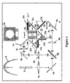
- a conventional LCoS projection system includes a light source 6 for generating a high power beam of light, and a polarization conversion light pipe (PCLP) 7 for ensuring substantially all of the light is linearly polarized, e.g. horizontally polarized.
- a first lensing element 8a passes the beam of light to a first folding mirror 9a, which directs the beam of light at a first dichroic filter 10.
- the first dichroic filter 10 separates out green light from the remaining light, and directs the green light via second and third lensing elements 8b and 8c, and second and third folding mirrors 9b and 9c to a first LCoS display panel 15a.
- the green light Prior to entering the first LCoS display panel 15a, the green light passes through a first polarizer 20a, such as a wire grid polarizer, and a first trim retarder PCE 21'.
- the polarization of a desired amount of the green light is rotated by the first display panel 15a, e.g. by 90° to horizontal polarization, whereby upon reflection the desired amount of green light is reflected by the first polarizer 20a towards the color cube 19 for transmission via the projection lens 18 onto a screen (not shown).
- the remaining light is directed via fourth and fifth lensing elements 8d and 8e, and a fourth folding mirror 9d to a second dichroic filter 12, which separates the remaining light into blue and red light.
- the red light is directed through a second polarizer 20b and a second trim retarder PCE 21 " to a second LCoS display panel 15b.
- the second display panel rotates the polarization of the desired amount of red light, whereby the polarizer 20b reflects the red light to the color cube 19 for transmission via the projection lens 18 onto the screen (not shown).
- the blue light passes through a third polarizer 20c and a third PCE 21'" to a third LCoS display panel 15c.
- the polarization of a desired amount of blue light is rotated, whereby upon reflection, the blue light is reflected by the third polarizer 20c to the color cube 19 for transmission via the projection lens 18 onto the screen (not shown).
- LCoS micro-displays typically have some residual birefringence in the dark (off-) state due to the orientation of the liquid crystal (LC) molecules in the LCoS cell.
- the linearly polarized light that illuminates the micro-display is slightly elliptically polarized upon reflection, which leads to dark state light leakage onto the screen, thereby limiting the contrast of the projection system.
- the trim retarder PCE 21' is placed in the light path in front of the LCoS display panel 15a. Unlike a conventional 1 ⁇ 2 ⁇ waveplate, a trim retarder provides only about 1 nm to 50 nm of retardance.
- the PCE 21' prepares the polarization state of the illuminating light, whereby upon reflection from the LCoS display panel 15a back through the PCE 21' the polarization state of the reflected light is effectively unchanged, i.e. rotated back to its original state of polarization, and no light is leaked onto the screen. It is also important that the polarization state of light reflected off of the PCE 21' is effectively unchanged or it will contribute to a loss in system contrast.
- LPP linearly photo-polymerizable polymer
- LCP photo-polymerizable liquid crystal polymer
- the oriented LPP layer induces (nucleates) orientation in the photo-polymerizable LCP layer.
- the oriented photo-polymerizable LCP layer is then fixed by exposure to light of sufficient energy to cause photo-induced cross-linking thereof.
- An object of the present invention is to overcome the shortcomings of the prior art.
- Another object of the present invention is to reduce the amount of reflection and interference events in a LPP/LCP PCE.
- the present invention relates to a liquid crystal (LC) display assembly for reducing back-reflection polarization conversion comprising:
- the polarization compensating element including a first polymeric photo aligned (LPP) layer; and a first cured photo-polymerizable liquid crystal polymer (LCP) layer mounted on said first LPP layer; wherein an in-plane fast axis orientation of the first LCP layer is substantially azimuthally aligned at an angle between 0° and 90° relative to an in-plane slow axis of the LC display panel.
- LPP polymeric photo aligned
- LCP liquid crystal polymer
- a trim retarder device for compensating residual in-plane birefringence of between 1 nm and 50 nm in a liquid crystal (LC) display panel comprising:
- a linearly photo-polymerizable polymer layer 1 is used to orient a photo-polymerizable liquid crystal polymer (LCP) film 2 by first, coating a transparent low-birefringence substrate 5 with a thin layer of the LPP 1.
- the substrate 5 can be a silica-based glass, a silica based ceramic, sapphire, polycarbonate, polyester, polychlortrifluoroethylene or polycyclic olefins, and typically has an index of refraction of between 1.35 and 2.7 @ 589 nm.
- a cured LCP layer has indices of refraction between 1.43 and 1.75 measured at @ 589 nm.
- the LPP layer 1 can be coated using any suitable method, including spin coated, dip coated, curtain coated or meniscus coated aligning.
- the LPP layer 1 is then heated to evaporate solvent, and exposed to linearly polarized ultra-violet light to cross-link the LPP layer 1 with the desired molecular orientation.
- the LCP layer 2 is coated on the photo aligned LPP layer 1 using one of the aforementioned suitable coating methods.
- the oriented LPP layer 1 induces (nucleates) orientation in the photo-polymerizable LCP layer 2, represented as aligned LCP molecules 3 along the X axis, forming a Type A plate.
- the oriented photo-polymerizable LCP layer 2 is then fixed by exposure to ultra-violet or e-beam energy of sufficient energy to cause photo-induced cross-linking thereof. Additional heating can be done to evaporate any residual solvent. Additional heating for a period of less than 15 minutes at a temperature up to 175 °C can be done to evaporate any residual solvent present in the LCP layer 2.
- the LPP/LCP film can be laminated to a top surface of the LC display panel or separated therefrom by an air gap.
- Optical elements using LPP/LCP birefringent film technology are manufactured relatively easily, and provide superior performance and stability compared to other types of liquid crystal (LC) or non LC based birefringent elements used as PCEs to correct for birefringence aberrations induced by LC based displays.
- LC liquid crystal
- PCE PCE
- the type and extent of compensation which LCP/LPP PCE trim retarders exhibit to achieve the final orientation correction characteristics required for an individual projection display apparatus, may be controlled by varying the amount of light energy, the incident angle and/or the azimuthal orientation of incidence of the polarized light used to cure the LPP polymer, the thickness of an LCP layer, coating multiple pairs of LPP and LCP layers, varying the angle of incidence of the polarized light used to cure the individual LPP layers, and varying the chemical structure of the LPP and/or the LCP layers.
- the assembly structure and the dielectric coatings also contribute to the type and extent of the compensation provided.
- Figures 4 and 5 illustrate a multiple layer plate, in which a second LPP layer 1' and a second LCP layer 2' are directly coated on previously deposited LPP and LCP layers 1 and 2, respectively.
- the optic axis of molecules 3 and 3' can have the same orientation or, as in Figure 5, the orientation can be orthogonal.
- the LPP layer 1 and LCP layer 2 are formed as above, but the second LPP layer 1' is cured with linearly polarized light in the Z direction, whereby the molecules 3' in the LCP layer 2' become aligned along the Z axis.
- the particular arrangement in Figure 5 forms an effective Type "-C" plate, which simulates a negative uniaxial material.
- a Type O plate is illustrated in Figure 6, and includes an LPP layer 1a tilted at a fixed axis along the azimuth running parallel to the electric field of the linearly polarized light used to cure the LPP layer 1a.
- the rods 4 represent the optic axis, which start out at approximately 82° near LPP surface 1a. As you move away from the LPP surface 1a the tilt angel of the LCP optic axis decreases to about 50° at the top surface of the LCP layer 2a.
- Various other combination of layers are also possible, including the deposition of a Type O plate on top of a Type A plate, as illustrated in Figure 7.
- combinations of single or multiple LPP/LCP pairs can be laminated together to form a single LPP/LCP trim retarder using a suitable adhesive.
- the effective negative C plate of Figure 5 is attached to a Type O plate of Figure 6 using a suitable adhesive 22.
- an in-plane fast axis orientation of the LCP layer 2 is azimuthally aligned nominally to an in-plane slow axis of the LCoS display panel, in which both the LCoS display panel and the LCP layer 2 have nominally the same input retardance magnitude.
- the in-plane retardance of the LCP layer 2 is greater than the LCoS panel, the LCP layer 2 can be azimuthally aligned at an angle between 0° and 90° relative to slow axis of the LCoS display panel to provide equal in-plane retardances.
- the level of in-plane compensation required for an LCoS is determined by rotating a type A-plate of known polarization in the light illuminating and reflected back off of the display panel in the dark state until maximum contrast is obtained.
- the level of PCE in-plane compensation required for the specific LCoS display panel is the same as the amount of compensation introduced by the known type A-plate. While the present invention relates to compensating for residual birefringence in an LC display panel, if the aforementioned process is conducted after assembly of the entire projection system, as illustrated in Figure 1, the trim retarder will actually compensate for any residual birefringence in the system, not just for in the LC display panel.
- Retardance measurements were carried out using a Hinds Exicor 150AT® (@ ⁇ 632.8 nm), with 1mm spatial resolution. A 76 mm diameter area in the center of the sample was found to have an average retardance of 21.74 nm with a non-uniformity of +/- 0.85 nm. The average orientation of the fast axis was 90.4° with a non-uniformity of+/- 0.3°.
- LPP/LCP trim retarders based upon typical LPP/LCP birefringent film pairs have significant light leakage that limits the achievable contrast, due to light which is back reflected with a partially converted polarization state from the LPP/LCP trim retarder itself.
- the back-reflected, polarization-converted light is due to a mismatch between the refractive indices on the interfaces between the cured LCP layer 2, the cured LPP alignment layer 1, the substrate 5, the air and the laminating adhesive (if used).
- these effects represent combinations of reflection and interference events that lead to changes in the retardance value and undesired changes in the polarization of the light passing through or reflecting off of the PCE, thereby degrading the performance of the LPP/LCP trim retarder.
- LPP/LCP films have relatively high ⁇ N birefringence values, for example LPP/LCP films using LCP Opalva 2130® (Vantico AG) have ⁇ N birefringence values >0.141 in the blue to >0.107 in the red.
- LCP layers in conventional applications e.g. for LC display polarizing filters
- One of the important properties of LCP layers in conventional applications e.g. for LC display polarizing filters, is having a high ⁇ N birefringence value, which is desirable for several reasons.
- the ability of LPP layers to induce orientation in a LCP layer is thickness limited, i.e. beyond a certain thickness of LCP layer the ability of the LPP layer to induce a controlled level of orientation in a LCP layer is diminished.
- LPP/LCP trim retarders made by known processes yield some level of contrast improvement in display applications when used as polarization compensation elements; however, the level of back reflection polarization conversion and interference events intrinsic to state of the art LPP/LCP films was found to be inferior to other types of materials used for compensation elements in display applications.
- the high level of in-plane birefringence in LPP/LCP trim retarders manufactured with high ⁇ N LCP material causes the polarization state of the reflected light to become partially converted because of the difference in reflection coefficients of the ordinary and extraordinary waves.
- the difference in reflection coefficients between the two waves makes it impossible to index match the LPP/LCP surface interfaces with any single material.
- One way to decrease the reflection and interference events in a LPP/LCP trim retarder is to minimize the ⁇ N birefringence properties of the LCP material, thereby closing the gap between the reflection coefficients of the ordinary and extraordinary waves, which lessens the back reflection and polarization conversion of the reflected light. Furthermore, minimizing the difference in reflection coefficients makes it possible to more closely match an anti-reflection (AR) coating thereto.
- AR coatings can only be optimized for one index of refraction, which in this case will be the average index of refraction between the ordinary and extraordinary indices of refraction. By reducing the difference between the ordinary and extraordinary indexes of refraction, the index of refraction of the AR coating becomes more closely matched to both.
- LCPs available for LPP/LCP coatings have intrinsically high ⁇ N birefringence values, e.g. >0.141 in the blue to > 0.107 in the red. Accordingly, ⁇ N birefringence values below the aforementioned conventional values and above 0.0001 are desired; however, values between 0.07 and 0.0001 are particularly useful, but values between 0.05 and 0.0001 and between 0.02 and 0.0001 in the visible spectrum are also useful for LPP/LCP trim retarders.
- the ⁇ N birefringence values of LPP/LCP coating made from material with intrinsically high ⁇ N birefringence values, can be treated to lower their ⁇ N birefringence values. Low effective in-plane ⁇ N birefringence can also be achieved using O-plate type LPP/LCP trim retarders.
- small quantities of isotropic organic compounds are introduced to the LCP layer to decrease the ⁇ N birefringence values of the LPP/LCP trim retarder.
- the isotropic organic compounds can be formulated into the LCP layer before coating or by immersing a practically cured LCP layer in the isotropic compound, and subsequently exposing the LCP layer to a second dose of UV radiation to complete the curing.
- the isotropic compound is selected to be capable of reacting with the LCP layer to prevent the migration of the LCP out of the cured film. Any isotropic formulation based upon compounds containing monomeric acrylate functional groups, that are physically compatible with the LCP formulation, will decrease the in-plane ⁇ N birefringence values.
- LCP formulation consists of 60% by weight ROF-5103® , Vantico AG., and 40% by weight of a mixed UV curing acrylate base adhesive, World Rock ZK-101® , Kyoritsu Chemical & Co. Ltd.
- a PCE produced using this formulation had a measured in-plane ⁇ N birefringence value of 0.067 @ 632.8 nm compared to the measured in-plane ⁇ N birefringence value of 0.1078 @ 632.8 nm of a PCE based upon an LCP layer make from neat ROF-5103® .
- the in-plane ⁇ N birefringence of LPP/LCP trim retarders and cured LPP/LCP layers can also be decreased by exposing them to UV radiation or e-beam energy at levels beyond that required to complete cross linking of the LCP layer, preferably at wavelengths less than 340 nm.
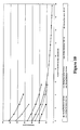
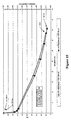
- Figures 10 and 11 illustrate the decrease in in-plane retardance, i.e. a decrease in in-plane ⁇ N, for LPP/LCP PCE's of various starting in-plane retardance values induced by extend exposure to UV energy.
- Figure 14 compares the average contrast for an untreated PCE retarder with an in-plane ⁇ N of 0.14 to that of UV treated PCE retarders with in-plane ⁇ N's of approximately 0.021 and 0.014.
- a detailed example of a method for manufacturing a LPP/LCP trim retarder with low ⁇ N birefringence properties due to increase exposure to UV energy is as follows. Clean a 50mm round 1 mm thick Fused silica substrate. Spin coat for 60 seconds at 3000 rpm with approximately 5 nm thick film of LPP, e.g. type SA2100® 2% in cyclopentanone, diluted to 0.5 wt% in cyuclopentanone). Bake the LPP film for 5 minutes at 180°C. Align the LPP by exposure to collimated linearly polarized light, e.g. 40 mJ/cm 2 @ wavelength approximately 300 nm to 340 nm, azimuthal orientation 0°, at normal incidence.
- collimated linearly polarized light e.g. 40 mJ/cm 2 @ wavelength approximately 300 nm to 340 nm, azimuthal orientation 0°, at normal incidence.
- LCP layer by spin coating directly on top of the LPP layer for 120 seconds @3000 rpm, e.g. type ROF-5103/25A® (25wt%), diluted to 15wt% in anisole, (Vantico AG). Anneal the coated sample at 51 °C for 5 minutes. Purge the coated sample in N 2 , and expose the coated sample to 360 J/cm 2 of UVB irradiation. Bake the coated sample for 10 minutes at 150 °C. At this point the LCP film exhibited an in-plane retardance of approximately 36 nm, and its in-plane birefringence was measured to be 0.11 at 633 nm.
- the film was then incrementally exposed to doses of high intensity UV irradiation (Fusion UV lamp).
- the in-plane retardance thereof was measured to be decreasing as a function of exposure dose.
- the in-plane retardance reached a level of approximately 3.7 nm, at which point it's in-plane birefringence was measured to be approximately 0.011 at 633 nm.
- An alternative method for lowering the ⁇ N birefringence values of an LPP/LCP trim retarder and LPP/LCP coatings is similar to the method described above, but instead of fully curing the LCP layer with the UV radiation, the LCP layer is exposed to a reduced level of UV radiation, such that only a homogenously distributed fraction of molecules in the LCP layer are cured. Then the LPP/LCP coatings are subjected to an additional heating step to randomize the orientation of a homogeneously distributed fraction of uncured molecules of the LCP layer. Subsequently, the LCP layer is completely cured by a second exposure to UV radiation, fixing the randomized orientation of the fraction of the LCP molecules, which were previously uncured.
- a detailed example of a method for manufacturing an LPP/LCP trim retarder with low ⁇ N birefringence properties due to a partial curing and heating is as follows.
- LCP layer by spin coating directly on top of the LPP layer for 120 seconds @ 3000 rpm, e.g. type ROF-5103/50A® (50wt%), Vantico AG. Anneal the coated sample at 51 °C for 5 minutes. Purge the coated sample in N 2 , and expose the coated sample to 0.024 mJ/cm 2 of UVB irradiation. At this point the LCP film was partially crosslinked, and exhibited a measured in-plane retardance of 311.3 nm and an in-plane birefringence of 0.11 at 633 nm.
- the film was then heated to 150 °C for 10 minutes under N 2 , and then cured by exposure to 1 J/cm 2 UVB, while at 150 °C and under N 2 atmosphere. Upon cooling back to room temperature, the in-plane retardance was measured to be 7.1 nm and the in-plane birefringence was approximately 0.0025.
- the ⁇ N birefringence values of LPP/LCP trim retarders and LPP/LCP coatings can also be decreased by exposing the cured LPP/LCP layers to elevated temperatures, e.g. between 50°C and 250°C, preferably at 145°C to 200°C, for extended periods of time, e.g. 30 to 60 hours, preferably 40 hours, in an non-oxidizing atmosphere.
- Figure 15 illustrates the decrease in in-plane retardence, i.e. a decrease in in-plane ⁇ N, for LPP/LCP retarders of various starting in-plane retardence values induced by extended exposure, i.e. 0 to 50 hours, to elevated temperatures, i.e. 250 °C.
- a plot of contrast vs. wavelength for a thermally treated LPP/LCP trim retarder is illustrated in Figure 16.
- a detailed example of a method for manufacturing an LPP/LCP trim retarder or LPP/LCP coatings with low in-plane ⁇ N birefringence properties due to extended exposure to thermal treatment is as follows. Clean a 100 mm square x 0.7 mm thick Corning-1737 glass substrate. AR coat one side of the glass substrate. Spin coat the other side of the glass substrate for 60 seconds at 3000 rpm with an approximately 50 nm thick film of LPP, e.g. type SA2100® 2% in cyclopentanone. Bake the LPP film for 5 minutes at 180°C. Align the LPP by exposure to collimated linearly polarized light, e.g.
- the in-plane retardance was measured to be decreasing as a function total time at 250 °C. Ultimately the in-plane retardance reached a level of 21 nm, at which point the in-plane birefringence was measured to be approximately 0.009 at 633 nm.
- the film was than laminated to another AR coated substrate (AR coated on side opposite that which was laminated) by an adhesive, which was an appropriate optical adhesive with index of refraction similar to that of the substrate and/or LCP material.
- LPP/LCP coating pairs made from a near homeotropic type LPP formulation e.g. ROP-103/2CP® or ROP-119/2CP® ; Rolic Technology Ltd., and a near homeotropic type LCP formulation, e.g. ROF5106/25A® ; Rolic Technology LTD.
- a near homeotropic type LCP formulation e.g. ROF5106/25A®
- Rolic Technology LTD. when aligned to induce near homeotropic alignment of the LPP/LCP coatings, can be used to produce low in-plane ⁇ N birefringence values LPP/LCP trim retarders and LPP/LCP coatings without extended thermal or UV treatments.
- the LPP layer can be oriented such that a near homeotropic orientation is induced in the near homeotropic type LCP formulation, e.g. ROF5106/25A® .
- Near homeotropic LCP coatings can achieve an optic axis orientation with an average tilt angle that is higher than formulations that do not possesses near homeotropic properties. As a result of a high average tilt angle the near homeotropic LCP coating have low in-plane ⁇ N birefringence.
- the in-plane ⁇ N birefringence of ROF5106/25A® can be lowered further by a short thermal treatment.
- a short thermal treatment As the LCP layer is cured a fraction of the LCP molecules, activated by the UV exposure, are trapped within the aligned matrix of the LCP layer.
- the LPP/LCP film undergoes a short heat treatment the mobility of these reactive fractions increases, which allows the reactive fractions to react and crosslink. This secondary crosslink takes place while these areas of the matrix are randomly oriented and no longer contribute to the LCP layers in-plane ⁇ N birefringence.
- the in-plane ⁇ N birefringence of the LCP film is lower than that of the same film before the short thermal treatment.
- Figure 17 illustrates a plot of in-plane ⁇ N birefringence at 632.8 nm vs. LCP optic axis tilt angles.
- Point A represents an A-plate, which has no tilt angle
- the Range A represents the original LPP/LCP O-plate materials, which have tilt angles less than 28°.
- Range B near homeotropic LPP/LCP materials
- the near homeotropic LCP coating can achieve an optic axis orientation with an average tilt angle that is higher than formulations that do not possess near homeotropic properties. As a result of a high average tilt angle the near homeotropic LCP coating has a low in-plane ⁇ N birefringence.
- a general procedure for coating near homeotropic LPP/LCP layers with low intrinsic ⁇ N birefringence values LCP on substrates and producing LPP/LCP trim retarders is as follows. Clean a 100mm square x 0.7 mm thick Corning-1737® glass substrate. AR coat one side of the glass. Spin coat the other side of the glass for 60 seconds at 3000 rpm with an approximately 50 nm thick film of LPP (type ROP-119/2CP® , Rolic Research). Bake the LPP film for 15 minutes at 180°C. Align the LPP by exposing the LPP to collimated linearly polarized light, e.g.
- another embodiment of the present invention relates to decreasing reflections created at material interfaces by applying AR coatings based upon dielectric layers at those interfaces.
- the dielectric layers can be utilized independently, but preferably in combination with LCP layers with low ⁇ N birefringence values.
- the introduction of dielectric layers into the LPP/LCP trim retarder structure enables the introduction of other desirable features, e.g. filter out UV and IR radiation which can cause deterioration of the LCP/LPP layers, color correction, chemical barrier and physical barrier layers.
- the incorporation of anti-reflection dielectric coatings and ultraviolet light dielectric filters into polarization compensating elements improves the stability of the LPP/LCP trim retarder and the contrast performance thereof by decreasing the amount of light reflected back from the LPP/LCP trim retarders substrate/air interfaces.
- the dielectric layers consist of different layers of inorganic, polymer, organic-inorganic blends and/or composite materials, and may be monolithic or built out of a stack of sub-layers with a thickness of between 2nm and 10 microns. Ideally, the dielectric layers consist of materials having a refractive index between 1.35 and 2.5.
- the dielectric layers can be optically isotropic or optically anisotropic. Preferably, the dielectric layers have > 85% transmission in the spectral range between 380 nm to 780 nm.
- dielectric layers are used to suppress spatial "retardance ripples" caused by multiple internal reflection and interference of light within a structure made out of a glass substrate, an LPP alignment layer and a birefringent LCP layer.
- Tests show that for a 20 nm LPP/LCP trim retarder coated on a glass substrate with no AR coatings, the peak-to-valley magnitude of the retardance ripple is approximately 3 to 5 nm.
- the spatial period of the ripples is typically observed to be on the order of 4 to 10 mm, and is related to the non-parallelism of the substrate.
- the transmitted light is the combination of a primary single-pass beam, and a secondary multiply-intemally-reflected beam of much lower amplitude.
- the multiply-reflected beam is considered as the sum of all multiple reflection orders.
- the secondary beam may be quite small in amplitude compared to the primary beam, it exhibits much higher retardance due to its multiple passes through the LCP retarder layer.
- the total transmitted retardance is therefore the net effect of the retardances, intensities, and phase relation of the primary and secondary beams.
- the phase relation will vary spatially over the substrate, if the substrate does not have perfect parallelism. Thus, for certain substrate thicknesses there will be a constructive interference effect, i.e. a peak of ripples, while for other thicknesses the interference will be destructive, i.e. a valley of ripples.
- Suppression of spatial retardance ripples is particularly important for applications which require a high degree of retardance uniformity.
- high antireflective coatings are applied to the interfaces, which contribute to multiple internal reflections resulting in consecutive constructive/destructive interference and the formation of the ripples.
- the purpose of the AR coating in this case is to greatly reduce the secondary beam's intensity contribution to the transmitted retardance, thereby suppressing the ripple magnitude, i.e. smaller peak-to-valley.
- Figure 18 illustrates a LPP/LCP trim retarder, which was fabricated as per the structure in Figure 3 with an AR coating 31 on the external surface of the substrate 5 for refractive index matching the air/substrate interface, and an AR coating 32 on the external surface of the LCP layer 2 for refractive index matching the air/LCP layer interface, whereby the retardance ripple peak-to-valley magnitude is reduced down to approximately 0.15 nm to 0.25 nm.
- a measure of polarization conversion due to reflections occurring at the various interfaces is the amount of light reflecting off of the LPP/LCP trim retarder in a polarization state orthogonal to the incident state, which is compared to the light passing through the LPP/LCP trim retarder.
- the contrast is infinite.
- Figure 20 illustrates the contrast for a 20 nm retarder as seen in Figure 19, illuminated from the top, with and without the additional dielectric layer 33 between the laminated layer 22 and the birefringent LCP layer 2.
- the additional dielectric layer 33 improves the contrast and reduces polarization conversion.
- Figures 21a, 21b, 22a and 22b illustrate other embodiments of the present invention in which dielectric layers are disposed between the various layers thereof.
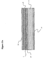
- dielectric film layers 34 and 35 are coated onto the surface of the substrates 5 prior to the LPP layer 1 and the adhesive layer 22, respectively.
- dielectric film layers 36 are further deposited between the LCP layer 2 of the first LPP/LCP pair and the LPP layer 1' of the second LPP/LCP pair for refractive index matching therewith.
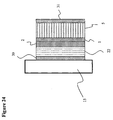
- the LPP/LCP trim retarder according to the present invention can be coated directly onto the LCoS display panel 15 forming a one piece liquid crystal display assembly.
- Dielectric layers 38 acting as an AR coating are preferably deposited between the LCoS panel 15 and the LPP/LCP trim retarder.
- the air/substrate AR coating 31 is deposited on the substrate 5, which is laminated to the LCP layer 2 with the adhesive layer 22.
- the substrate 5 and the adhesive layer 22 could also be removed leaving the LPP layer 1 and the LCP layer 2 supported by the LCoS display panel 15.
- the LPP layer 1 and the LCP layer 2 can be coated on the substrate 5, and then laminated onto the LCoS display panel 15 utilizing a suitable adhesive 22.
- AR coating 31 is again deposited at the air/substrate interface, while an AR coating 39 is deposited at the adhesive/display panel interface.
- the substrate 5 can be removed leaving the LPP layer 1 and the LCP layer 2 supported by the LCoS display panel 15.
Landscapes
- Physics & Mathematics (AREA)
- General Physics & Mathematics (AREA)
- Optics & Photonics (AREA)
- Chemical & Material Sciences (AREA)
- Crystallography & Structural Chemistry (AREA)
- Nonlinear Science (AREA)
- Mathematical Physics (AREA)
- Polarising Elements (AREA)
- Liquid Crystal (AREA)
- Steering Control In Accordance With Driving Conditions (AREA)
- Vehicle Body Suspensions (AREA)
Abstract
Description
- The present invention relates to a polarization controlling element (PCE) for liquid crystal display systems, and in particular to a trim retarder PCE, which uses a linearly photo-polymerizable polymer (LPP) to orient a photo-polymerizable liquid crystal polymer (LCP) film for increasing contrast of a liquid crystal on silicon (LCoS) micro-display based projection display system.
- With reference to Figure 1, a conventional LCoS projection system includes a
light source 6 for generating a high power beam of light, and a polarization conversion light pipe (PCLP) 7 for ensuring substantially all of the light is linearly polarized, e.g. horizontally polarized. Afirst lensing element 8a passes the beam of light to afirst folding mirror 9a, which directs the beam of light at a firstdichroic filter 10. The firstdichroic filter 10 separates out green light from the remaining light, and directs the green light via second andthird lensing elements third folding mirrors LCoS display panel 15a. Prior to entering the firstLCoS display panel 15a, the green light passes through afirst polarizer 20a, such as a wire grid polarizer, and a first trim retarder PCE 21'. The polarization of a desired amount of the green light is rotated by thefirst display panel 15a, e.g. by 90° to horizontal polarization, whereby upon reflection the desired amount of green light is reflected by thefirst polarizer 20a towards thecolor cube 19 for transmission via theprojection lens 18 onto a screen (not shown). - The remaining light is directed via fourth and
fifth lensing elements fourth folding mirror 9d to a seconddichroic filter 12, which separates the remaining light into blue and red light. The red light is directed through asecond polarizer 20b and a second trim retarder PCE 21 " to a secondLCoS display panel 15b. As above, the second display panel rotates the polarization of the desired amount of red light, whereby thepolarizer 20b reflects the red light to thecolor cube 19 for transmission via theprojection lens 18 onto the screen (not shown). - Similarly, the blue light passes through a
third polarizer 20c and a third PCE 21'" to a thirdLCoS display panel 15c. The polarization of a desired amount of blue light is rotated, whereby upon reflection, the blue light is reflected by thethird polarizer 20c to thecolor cube 19 for transmission via theprojection lens 18 onto the screen (not shown). - LCoS micro-displays typically have some residual birefringence in the dark (off-) state due to the orientation of the liquid crystal (LC) molecules in the LCoS cell. Thus, the linearly polarized light that illuminates the micro-display is slightly elliptically polarized upon reflection, which leads to dark state light leakage onto the screen, thereby limiting the contrast of the projection system. To improve the system contrast and compensate for the residual retardance, the trim retarder PCE 21' is placed in the light path in front of the
LCoS display panel 15a. Unlike a conventional ½λ waveplate, a trim retarder provides only about 1 nm to 50 nm of retardance. The PCE 21' prepares the polarization state of the illuminating light, whereby upon reflection from theLCoS display panel 15a back through the PCE 21' the polarization state of the reflected light is effectively unchanged, i.e. rotated back to its original state of polarization, and no light is leaked onto the screen. It is also important that the polarization state of light reflected off of the PCE 21' is effectively unchanged or it will contribute to a loss in system contrast. - United States Patents Nos. 6,215,539 issued to Schadt et al on April 10, 2001, and 6,160,597 issued to Schadt et al on December 12, 2000 teach a method of manufacturing birefringent films that effect the polarization state of light for use in conventional ¼λ and ½λ waveplates. A linearly photo-polymerizable polymer (LPP) is used to orient a photo-polymerizable liquid crystal polymer (LCP) film by coating a transparent low-birefringence substrate with a thin layer of the LPP, aligning the LPP layer by exposure to linearly polarized light, and coating the photo aligned layer of LPP with the LCP layer. During thermal treatment of the structure, the oriented LPP layer induces (nucleates) orientation in the photo-polymerizable LCP layer. The oriented photo-polymerizable LCP layer is then fixed by exposure to light of sufficient energy to cause photo-induced cross-linking thereof.
- An object of the present invention is to overcome the shortcomings of the prior art.
- Another object of the present invention is to reduce the amount of reflection and interference events in a LPP/LCP PCE.
- According to the present invention, these objects are achieved by a liquid crystal (LC) display assembly as defined in
claim 1 and a method as defined inclaim 12. The dependent claims define preferred and advantageous embodiments of the invention. - Accordingly, the present invention relates to a liquid crystal (LC) display assembly for reducing back-reflection polarization conversion comprising:
- an LC display panel having residual birefringence in a dark state due to the orientation of liquid crystal molecules therein; and a polarization compensating element for at least partially compensating for the residual birefringence.
-
- The polarization compensating element including a first polymeric photo aligned (LPP) layer; and a first cured photo-polymerizable liquid crystal polymer (LCP) layer mounted on said first LPP layer;
wherein an in-plane fast axis orientation of the first LCP layer is substantially azimuthally aligned at an angle between 0° and 90° relative to an in-plane slow axis of the LC display panel. - Another feature of the present invention relates to a trim retarder device for compensating residual in-plane birefringence of between 1 nm and 50 nm in a liquid crystal (LC) display panel comprising:
- a first polymeric photo aligned (LPP) layer; and
- a first cured photo-polymerizable liquid crystal polymer (LCP) layer having a relatively low in-plane ΔN birefringence value between 0.001 to 0.07 in the visible spectrum mounted on said first LPP layer.
-
- The invention will be described in greater detail with reference to the accompanying drawings which represent preferred embodiments thereof, wherein:
- Figure 1 is a schematic representation of a LCoS projection system;
- Figure 2 is a schematic representation of a Type A LPP/LCP trim retarder according to the present invention;
- Figure 3 is a side view of the trim retarder of Fig 2;
- Figure 4 is a side view of a multiple layer LPP/LCP trim retarder;
- Figure 5 is a schematic representation of an effective negative Type C LPP/LCP trim retarder;
- Figure 6 is a schematic representation of a Type O LPP/LCP trim retarder;
- Figure 7 is a schematic representation of a Type O trim retarder plate deposited on top of a Type A trim retarder plate;
- Figure 8 is a side view of a Type C plate connected to a Type O plate;
- Figure 9 is a plot of the calculated and measured ne, no, and ΔN vs. LCP films with different weight per cent of isotropic diluent;
- Figure 10 is a plot of retardance for LPP/LCP retarders vs ultra-violet energy beyond that necessary to cure the LCP layer;
- Figure 11 is a plot of relative loss in retardance for LPP/LCP retarders vs. ultra-violet energy beyond that necessary to cure the LCP layer;
- Figure 12 is a plot of average contrast vs. wavelength of an untreated 4nm LPP/LCP trim retarder;
- Figure 13 is a plot of contrast of an LPP/LCP trim retarder exposed to ultra-violet radiation to reduce the ΔN birefringence value vs. wavelength;
- Figure 14 is a plot of average contrast of UV-treated and untreated LPP/LCP trim retarders vs. wavelength;
- Figure 15 is a plot of relative loss in retardance for LPP/LCP trim retarders vs. time of heat treatment at 250 °C in a nitrogen atmosphere;
- Figure 16 is a plot of contrast of a LPP/LCP trim retarder thermally treated at 250 °C in a nitrogen atmosphere for a period of time required to develop a retardance of 4 nm vs. wavelength;
- Figure 17 is a plot of in-plane ΔN birefringence at 632.8 nm vs. LCP optic axis tilt angle;
- Figure 18 is a cross-sectional view of a LPP/LCP trim retarder with dielectric layers on the outer surfaces thereof;
- Figure 19 is a cross-sectional view of a LPP/LCP trim retarder with a laminated second substrate and a dielectric layer between the LPP/LCP trim retarder and the second substrate;
- Figure 20 is a plot of contrast vs. wavelength for the LPP/LCP trim retarder of Fig. 19 with and without the dielectric layer;
- Figure 21a is a cross-sectional view of a LPP/LCP trim retarder with dielectric layers on both sides of the substrate;
- Figure 21b is a cross-sectional view of a LPP/LCP trim retarder with dielectric layers on both sides of both substrates and in between the other layers;
- Figure 22a is a cross-sectional view of a multiple layer LPP/LCP trim retarder with dielectric layers on both sides of the substrate and in between the other layers;
- Figure 22b is a cross-sectional view of a laminated LPP/LCP trim retarder with dielectric layers on both sides of both substrates and in between the other layers;
- Figure 23 is a cross-sectional view of a LPP/LCP trim retarder deposited directly onto a LC display panel; and
- Figure 24 is a cross-sectional view of an LPP/LCP trim retarder laminated onto a LC display panel.
-
- With reference to Figures 2 and 3, a linearly photo-polymerizable polymer layer 1 (LPP) is used to orient a photo-polymerizable liquid crystal polymer (LCP)
film 2 by first, coating a transparent low-birefringence substrate 5 with a thin layer of theLPP 1. Thesubstrate 5 can be a silica-based glass, a silica based ceramic, sapphire, polycarbonate, polyester, polychlortrifluoroethylene or polycyclic olefins, and typically has an index of refraction of between 1.35 and 2.7 @ 589 nm. Typically, a cured LCP layer has indices of refraction between 1.43 and 1.75 measured at @ 589 nm. TheLPP layer 1 can be coated using any suitable method, including spin coated, dip coated, curtain coated or meniscus coated aligning. TheLPP layer 1 is then heated to evaporate solvent, and exposed to linearly polarized ultra-violet light to cross-link theLPP layer 1 with the desired molecular orientation. TheLCP layer 2 is coated on the photo alignedLPP layer 1 using one of the aforementioned suitable coating methods. During subsequent thermal treatment of the structure, the orientedLPP layer 1 induces (nucleates) orientation in the photo-polymerizable LCP layer 2, represented as alignedLCP molecules 3 along the X axis, forming a Type A plate. The oriented photo-polymerizable LCP layer 2 is then fixed by exposure to ultra-violet or e-beam energy of sufficient energy to cause photo-induced cross-linking thereof. Additional heating can be done to evaporate any residual solvent. Additional heating for a period of less than 15 minutes at a temperature up to 175 °C can be done to evaporate any residual solvent present in theLCP layer 2. The LPP/LCP film can be laminated to a top surface of the LC display panel or separated therefrom by an air gap. - Optical elements using LPP/LCP birefringent film technology are manufactured relatively easily, and provide superior performance and stability compared to other types of liquid crystal (LC) or non LC based birefringent elements used as PCEs to correct for birefringence aberrations induced by LC based displays. The type and extent of compensation, which LCP/LPP PCE trim retarders exhibit to achieve the final orientation correction characteristics required for an individual projection display apparatus, may be controlled by varying the amount of light energy, the incident angle and/or the azimuthal orientation of incidence of the polarized light used to cure the LPP polymer, the thickness of an LCP layer, coating multiple pairs of LPP and LCP layers, varying the angle of incidence of the polarized light used to cure the individual LPP layers, and varying the chemical structure of the LPP and/or the LCP layers. Moreover, the assembly structure and the dielectric coatings also contribute to the type and extent of the compensation provided.
- Figures 4 and 5 illustrate a multiple layer plate, in which a second LPP layer 1' and a second LCP layer 2' are directly coated on previously deposited LPP and
LCP layers molecules 3 and 3' can have the same orientation or, as in Figure 5, the orientation can be orthogonal. In this case, theLPP layer 1 andLCP layer 2 are formed as above, but the second LPP layer 1' is cured with linearly polarized light in the Z direction, whereby the molecules 3' in the LCP layer 2' become aligned along the Z axis. The particular arrangement in Figure 5 forms an effective Type "-C" plate, which simulates a negative uniaxial material. - A Type O plate is illustrated in Figure 6, and includes an LPP layer 1a tilted at a fixed axis along the azimuth running parallel to the electric field of the linearly polarized light used to cure the LPP layer 1a. The
rods 4 represent the optic axis, which start out at approximately 82° near LPP surface 1a. As you move away from the LPP surface 1a the tilt angel of the LCP optic axis decreases to about 50° at the top surface of theLCP layer 2a. Various other combination of layers are also possible, including the deposition of a Type O plate on top of a Type A plate, as illustrated in Figure 7. - As an alternative to coating multiple LPP/LCP layer pairs consecutively, combinations of single or multiple LPP/LCP pairs can be laminated together to form a single LPP/LCP trim retarder using a suitable adhesive. With reference to Figure 8, the effective negative C plate of Figure 5 is attached to a Type O plate of Figure 6 using a
suitable adhesive 22. - Generally, in use, an in-plane fast axis orientation of the
LCP layer 2 is azimuthally aligned nominally to an in-plane slow axis of the LCoS display panel, in which both the LCoS display panel and theLCP layer 2 have nominally the same input retardance magnitude. Alternatively, if the in-plane retardance of theLCP layer 2 is greater than the LCoS panel, theLCP layer 2 can be azimuthally aligned at an angle between 0° and 90° relative to slow axis of the LCoS display panel to provide equal in-plane retardances. The level of in-plane compensation required for an LCoS is determined by rotating a type A-plate of known polarization in the light illuminating and reflected back off of the display panel in the dark state until maximum contrast is obtained. The level of PCE in-plane compensation required for the specific LCoS display panel is the same as the amount of compensation introduced by the known type A-plate. While the present invention relates to compensating for residual birefringence in an LC display panel, if the aforementioned process is conducted after assembly of the entire projection system, as illustrated in Figure 1, the trim retarder will actually compensate for any residual birefringence in the system, not just for in the LC display panel. - A detailed procedure for coating LPP/LCP pairs with a high intrinsic ΔN birefringence value LCP on substrates and producing a LPP/LCP trim retarder is as follows.
- Clean a 100 mm X 0.7 mm square piece of Coming 1737® glass. Spin coat a 48 nm thick film of LPP to the glass substrate (2% solids solution of Staralign 2100® Vantico AG) for 30 seconds @ 3000 RPM. Bake the LPP coated glass at 180 °C for 5 minutes. Expose the LPP to collimated linearly polarized UV light to align the LPP molecules therewith, e.g. 250 mJ/cm2 at λ = 300 nm to 340 nm, Φe= 0° =electric field orientation to substrate reference edge. Spin coat a LCP layer directly on top of the aligned LPP layer, e.g. 15% solids solution of ROF-5103® Vantico AG, for 60 seconds at 3350 RPM. Anneal the coated sample at 51 °C for 5 minutes. Expose the coated sample to 1 J/cm2 of UVB light under nitrogen atmosphere, then bake the LPP/LCP pair at 160 °C for 10 minutes.
- Retardance measurements were carried out using a Hinds Exicor 150AT® (@ λ∼632.8 nm), with 1mm spatial resolution. A 76 mm diameter area in the center of the sample was found to have an average retardance of 21.74 nm with a non-uniformity of +/- 0.85 nm. The average orientation of the fast axis was 90.4° with a non-uniformity of+/- 0.3°.
- Unfortunately, LPP/LCP trim retarders based upon typical LPP/LCP birefringent film pairs have significant light leakage that limits the achievable contrast, due to light which is back reflected with a partially converted polarization state from the LPP/LCP trim retarder itself. The back-reflected, polarization-converted light is due to a mismatch between the refractive indices on the interfaces between the cured
LCP layer 2, the curedLPP alignment layer 1, thesubstrate 5, the air and the laminating adhesive (if used). In general terms, these effects represent combinations of reflection and interference events that lead to changes in the retardance value and undesired changes in the polarization of the light passing through or reflecting off of the PCE, thereby degrading the performance of the LPP/LCP trim retarder. - Commercial LPP/LCP films have relatively high ΔN birefringence values, for example LPP/LCP films using LCP Opalva 2130® (Vantico AG) have ΔN birefringence values >0.141 in the blue to >0.107 in the red. One of the important properties of LCP layers in conventional applications, e.g. for LC display polarizing filters, is having a high ΔN birefringence value, which is desirable for several reasons. The ability of LPP layers to induce orientation in a LCP layer is thickness limited, i.e. beyond a certain thickness of LCP layer the ability of the LPP layer to induce a controlled level of orientation in a LCP layer is diminished. Furthermore, spin coating is a desired method of application for LPP/LCP coatings; however, beyond a specific thickness it becomes difficult to cure LCP films because of optical absorption properties of the photo-initiators and the LCP polymer. As a result, manufacturers have focused their efforts on developing LCP materials that have high ΔN birefringence values, which enable a relatively thin single pair of LPP/LCP films to be manufactured for LC display polarization filter applications. Figure 9 illustrates the effects of increasing the amount of isotropic diluents on the refractive indices ne and no.
- LPP/LCP trim retarders made by known processes yield some level of contrast improvement in display applications when used as polarization compensation elements; however, the level of back reflection polarization conversion and interference events intrinsic to state of the art LPP/LCP films was found to be inferior to other types of materials used for compensation elements in display applications.
- The high level of in-plane birefringence in LPP/LCP trim retarders manufactured with high ΔN LCP material causes the polarization state of the reflected light to become partially converted because of the difference in reflection coefficients of the ordinary and extraordinary waves. The difference in reflection coefficients between the two waves makes it impossible to index match the LPP/LCP surface interfaces with any single material.
- One way to decrease the reflection and interference events in a LPP/LCP trim retarder is to minimize the ΔN birefringence properties of the LCP material, thereby closing the gap between the reflection coefficients of the ordinary and extraordinary waves, which lessens the back reflection and polarization conversion of the reflected light. Furthermore, minimizing the difference in reflection coefficients makes it possible to more closely match an anti-reflection (AR) coating thereto. AR coatings can only be optimized for one index of refraction, which in this case will be the average index of refraction between the ordinary and extraordinary indices of refraction. By reducing the difference between the ordinary and extraordinary indexes of refraction, the index of refraction of the AR coating becomes more closely matched to both. Conventional LCPs available for LPP/LCP coatings have intrinsically high ΔN birefringence values, e.g. >0.141 in the blue to > 0.107 in the red. Accordingly, ΔN birefringence values below the aforementioned conventional values and above 0.0001 are desired; however, values between 0.07 and 0.0001 are particularly useful, but values between 0.05 and 0.0001 and between 0.02 and 0.0001 in the visible spectrum are also useful for LPP/LCP trim retarders. In accordance with the present invention, the ΔN birefringence values of LPP/LCP coating, made from material with intrinsically high ΔN birefringence values, can be treated to lower their ΔN birefringence values. Low effective in-plane ΔN birefringence can also be achieved using O-plate type LPP/LCP trim retarders.
- In a first example, small quantities of isotropic organic compounds are introduced to the LCP layer to decrease the ΔN birefringence values of the LPP/LCP trim retarder. The isotropic organic compounds can be formulated into the LCP layer before coating or by immersing a practically cured LCP layer in the isotropic compound, and subsequently exposing the LCP layer to a second dose of UV radiation to complete the curing. Preferably, the isotropic compound is selected to be capable of reacting with the LCP layer to prevent the migration of the LCP out of the cured film. Any isotropic formulation based upon compounds containing monomeric acrylate functional groups, that are physically compatible with the LCP formulation, will decrease the in-plane ΔN birefringence values. One such LCP formulation consists of 60% by weight ROF-5103® , Vantico AG., and 40% by weight of a mixed UV curing acrylate base adhesive, World Rock ZK-101® , Kyoritsu Chemical & Co. Ltd. A PCE produced using this formulation had a measured in-plane ΔN birefringence value of 0.067 @ 632.8 nm compared to the measured in-plane ΔN birefringence value of 0.1078 @ 632.8 nm of a PCE based upon an LCP layer make from neat ROF-5103® .
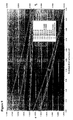
- The in-plane ΔN birefringence of LPP/LCP trim retarders and cured LPP/LCP layers can also be decreased by exposing them to UV radiation or e-beam energy at levels beyond that required to complete cross linking of the LCP layer, preferably at wavelengths less than 340 nm. Figures 10 and 11 illustrate the decrease in in-plane retardance, i.e. a decrease in in-plane ΔN, for LPP/LCP PCE's of various starting in-plane retardance values induced by extend exposure to UV energy. In contrast to an untreated PCE retarder, illustrated in Figure 12, a PCE retarder treated with 835 J/cm2 of UVB energy until the in-plane ΔN is lowered to 0.015, as in Figure 13, consistently provides a contrast over 20000. Figure 14 compares the average contrast for an untreated PCE retarder with an in-plane ΔN of 0.14 to that of UV treated PCE retarders with in-plane ΔN's of approximately 0.021 and 0.014.
- A detailed example of a method for manufacturing a LPP/LCP trim retarder with low ΔN birefringence properties due to increase exposure to UV energy is as follows. Clean a
50mm round 1 mm thick Fused silica substrate. Spin coat for 60 seconds at 3000 rpm with approximately 5 nm thick film of LPP, e.g.type SA2100® 2% in cyclopentanone, diluted to 0.5 wt% in cyuclopentanone). Bake the LPP film for 5 minutes at 180°C. Align the LPP by exposure to collimated linearly polarized light, e.g. 40 mJ/cm2 @ wavelength approximately 300 nm to 340 nm,azimuthal orientation 0°, at normal incidence. Apply an LCP layer by spin coating directly on top of the LPP layer for 120 seconds @3000 rpm, e.g. type ROF-5103/25A® (25wt%), diluted to 15wt% in anisole, (Vantico AG). Anneal the coated sample at 51 °C for 5 minutes. Purge the coated sample in N2, and expose the coated sample to 360 J/cm2 of UVB irradiation. Bake the coated sample for 10 minutes at 150 °C. At this point the LCP film exhibited an in-plane retardance of approximately 36 nm, and its in-plane birefringence was measured to be 0.11 at 633 nm. The film was then incrementally exposed to doses of high intensity UV irradiation (Fusion UV lamp). The in-plane retardance thereof was measured to be decreasing as a function of exposure dose. Ultimately, after receiving a dose of approximately 40 J/cm2 at 240 nm to 420 nm the in-plane retardance reached a level of approximately 3.7 nm, at which point it's in-plane birefringence was measured to be approximately 0.011 at 633 nm. - An alternative method for lowering the ΔN birefringence values of an LPP/LCP trim retarder and LPP/LCP coatings is similar to the method described above, but instead of fully curing the LCP layer with the UV radiation, the LCP layer is exposed to a reduced level of UV radiation, such that only a homogenously distributed fraction of molecules in the LCP layer are cured. Then the LPP/LCP coatings are subjected to an additional heating step to randomize the orientation of a homogeneously distributed fraction of uncured molecules of the LCP layer. Subsequently, the LCP layer is completely cured by a second exposure to UV radiation, fixing the randomized orientation of the fraction of the LCP molecules, which were previously uncured.
- A detailed example of a method for manufacturing an LPP/LCP trim retarder with low ΔN birefringence properties due to a partial curing and heating is as follows. A 100mm square x 0.7 mm thick Corning-1737® glass substrate. AR coat on one side of the glass substrate. Spin coat the other side of the glass substrate for 60 seconds at 3000 rpm with an approximately 50 nm thick film of LPP, e.g.
type SA2100® 2% in cyclopentanone. Bake the LPP film for 5 minutes at 180°C. Align the LPP by exposure to collimated linearly polarized light, e.g. 250 mJ/cm2 @ wavelength approximately 300 nm to 340 nm,azimuthal orientation 0°, at normal incidence. Apply an LCP layer by spin coating directly on top of the LPP layer for 120 seconds @ 3000 rpm, e.g. type ROF-5103/50A® (50wt%), Vantico AG. Anneal the coated sample at 51 °C for 5 minutes. Purge the coated sample in N2, and expose the coated sample to 0.024 mJ/cm2 of UVB irradiation. At this point the LCP film was partially crosslinked, and exhibited a measured in-plane retardance of 311.3 nm and an in-plane birefringence of 0.11 at 633 nm. The film was then heated to 150 °C for 10 minutes under N2, and then cured by exposure to 1 J/cm2 UVB, while at 150 °C and under N2 atmosphere. Upon cooling back to room temperature, the in-plane retardance was measured to be 7.1 nm and the in-plane birefringence was approximately 0.0025. - The ΔN birefringence values of LPP/LCP trim retarders and LPP/LCP coatings can also be decreased by exposing the cured LPP/LCP layers to elevated temperatures, e.g. between 50°C and 250°C, preferably at 145°C to 200°C, for extended periods of time, e.g. 30 to 60 hours, preferably 40 hours, in an non-oxidizing atmosphere. Figure 15 illustrates the decrease in in-plane retardence, i.e. a decrease in in-plane ΔN, for LPP/LCP retarders of various starting in-plane retardence values induced by extended exposure, i.e. 0 to 50 hours, to elevated temperatures, i.e. 250 °C. A plot of contrast vs. wavelength for a thermally treated LPP/LCP trim retarder is illustrated in Figure 16.
- A detailed example of a method for manufacturing an LPP/LCP trim retarder or LPP/LCP coatings with low in-plane ΔN birefringence properties due to extended exposure to thermal treatment is as follows. Clean a 100 mm square x 0.7 mm thick Corning-1737 glass substrate. AR coat one side of the glass substrate. Spin coat the other side of the glass substrate for 60 seconds at 3000 rpm with an approximately 50 nm thick film of LPP, e.g.
type SA2100® 2% in cyclopentanone. Bake the LPP film for 5 minutes at 180°C. Align the LPP by exposure to collimated linearly polarized light, e.g. 40 mJ/cm2 @ wavelength 300∼340 nm,azimuthal orientation 0°, at normal incidence. Apply an LCP layer directly on top of the LPP layer by spin coating for 120 seconds @ 2300 rpm, e.g. type ROF-5103/50A® (50wt%), Vantico AG. Anneal the coated sample at 51 °C for 10 minutes. Purge the coated sample in N2 and expose the coated sample to 1 J/cm2 of UVB irradiation. At this point the LCP film exhibited an in-plane retardance of approximately 271 nm, and an in-plane birefringence of 0.11 at 633 nm. The film was then baked at 250°C for 40 hours. The in-plane retardance was measured to be decreasing as a function total time at 250 °C. Ultimately the in-plane retardance reached a level of 21 nm, at which point the in-plane birefringence was measured to be approximately 0.009 at 633 nm. The film was than laminated to another AR coated substrate (AR coated on side opposite that which was laminated) by an adhesive, which was an appropriate optical adhesive with index of refraction similar to that of the substrate and/or LCP material. - LPP/LCP coating pairs made from a near homeotropic type LPP formulation, e.g. ROP-103/2CP® or ROP-119/2CP® ; Rolic Technology Ltd., and a near homeotropic type LCP formulation, e.g. ROF5106/25A® ; Rolic Technology LTD., when aligned to induce near homeotropic alignment of the LPP/LCP coatings, can be used to produce low in-plane ΔN birefringence values LPP/LCP trim retarders and LPP/LCP coatings without extended thermal or UV treatments. By exposing LPP ROP-103/2CP® or ROP-119/2CP® coating formulations to linear polarized light, while controlling the amount of light energy, the incident angle, and the azimuthal orientation of incidence of the polarized light used to cure the LPP polymer, the LPP layer can be oriented such that a near homeotropic orientation is induced in the near homeotropic type LCP formulation, e.g. ROF5106/25A® . Near homeotropic LCP coatings can achieve an optic axis orientation with an average tilt angle that is higher than formulations that do not possesses near homeotropic properties. As a result of a high average tilt angle the near homeotropic LCP coating have low in-plane ΔN birefringence. The in-plane ΔN birefringence of ROF5106/25A® can be lowered further by a short thermal treatment. As the LCP layer is cured a fraction of the LCP molecules, activated by the UV exposure, are trapped within the aligned matrix of the LCP layer. As the LPP/LCP film undergoes a short heat treatment the mobility of these reactive fractions increases, which allows the reactive fractions to react and crosslink. This secondary crosslink takes place while these areas of the matrix are randomly oriented and no longer contribute to the LCP layers in-plane ΔN birefringence. As a result, the in-plane ΔN birefringence of the LCP film is lower than that of the same film before the short thermal treatment.
- Figure 17 illustrates a plot of in-plane ΔN birefringence at 632.8 nm vs. LCP optic axis tilt angles. Point A represents an A-plate, which has no tilt angle, and the Range A represents the original LPP/LCP O-plate materials, which have tilt angles less than 28°. However, with the aforementioned near homeotropic LPP/LCP materials (Range B), tilt angles of between 35° and 75°, can be obtained, which corresponds to in-plane ΔN birefringence values of between 0.07 and 0.01.
- For Example: While exposing an ROP-103/2CP® or an ROP-119/2CP® LPP coating formulation to linear polarized light, the amount of light energy, the incident angle, and the azimuthal orientation of incidence is used to orient the LPP, whereby a near homeotropic orientation can be induced in a near homeotropic type LCP formulation, e.g. ROF5106/25A® . The near homeotropic LCP coating can achieve an optic axis orientation with an average tilt angle that is higher than formulations that do not possess near homeotropic properties. As a result of a high average tilt angle the near homeotropic LCP coating has a low in-plane ΔN birefringence.
- A general procedure for coating near homeotropic LPP/LCP layers with low intrinsic ΔN birefringence values LCP on substrates and producing LPP/LCP trim retarders is as follows. Clean a 100mm square x 0.7 mm thick Corning-1737® glass substrate. AR coat one side of the glass. Spin coat the other side of the glass for 60 seconds at 3000 rpm with an approximately 50 nm thick film of LPP (type ROP-119/2CP® , Rolic Research). Bake the LPP film for 15 minutes at 180°C. Align the LPP by exposing the LPP to collimated linearly polarized light, e.g. 1200 mJ/cm2 @ wavelength 300~340 nm,
azimuthal orientation 0°, angle ofincidence 40° off normal. Apply an LCP layer by spin coating directly on top of the LPP layer for 120 seconds @ 3000 rpm, e.g. type ROF-5106/25A® (25wt%), diluted to 18wt% in anisole, Rolic Research. Anneal the coated sample at 51 °C for 5 minutes. Purge the coated sample in N2, and expose the coated sample to 3 J/cm2 of UVA irradiation. Bake the coated sample for 10 minutes at 150 °C. Laminate the coated sample to another AR coated substrate (AR coated on side opposite that which was laminated) with an adhesive, which is an appropriate optical adhesive with index of refraction similar to that of the glass substrate and/or LCP material. - With reference to Figures 18 to 22, another embodiment of the present invention relates to decreasing reflections created at material interfaces by applying AR coatings based upon dielectric layers at those interfaces. The dielectric layers can be utilized independently, but preferably in combination with LCP layers with low ΔN birefringence values. The introduction of dielectric layers into the LPP/LCP trim retarder structure enables the introduction of other desirable features, e.g. filter out UV and IR radiation which can cause deterioration of the LCP/LPP layers, color correction, chemical barrier and physical barrier layers. The incorporation of anti-reflection dielectric coatings and ultraviolet light dielectric filters into polarization compensating elements improves the stability of the LPP/LCP trim retarder and the contrast performance thereof by decreasing the amount of light reflected back from the LPP/LCP trim retarders substrate/air interfaces. The dielectric layers consist of different layers of inorganic, polymer, organic-inorganic blends and/or composite materials, and may be monolithic or built out of a stack of sub-layers with a thickness of between 2nm and 10 microns. Ideally, the dielectric layers consist of materials having a refractive index between 1.35 and 2.5. The dielectric layers can be optically isotropic or optically anisotropic. Preferably, the dielectric layers have > 85% transmission in the spectral range between 380 nm to 780 nm.
- In accordance with one embodiment of the present invention, dielectric layers are used to suppress spatial "retardance ripples" caused by multiple internal reflection and interference of light within a structure made out of a glass substrate, an LPP alignment layer and a birefringent LCP layer. Tests show that for a 20 nm LPP/LCP trim retarder coated on a glass substrate with no AR coatings, the peak-to-valley magnitude of the retardance ripple is approximately 3 to 5 nm. The spatial period of the ripples is typically observed to be on the order of 4 to 10 mm, and is related to the non-parallelism of the substrate.
- The transmitted light is the combination of a primary single-pass beam, and a secondary multiply-intemally-reflected beam of much lower amplitude. For simplicity the multiply-reflected beam is considered as the sum of all multiple reflection orders. Although the secondary beam may be quite small in amplitude compared to the primary beam, it exhibits much higher retardance due to its multiple passes through the LCP retarder layer. The total transmitted retardance is therefore the net effect of the retardances, intensities, and phase relation of the primary and secondary beams. The phase relation will vary spatially over the substrate, if the substrate does not have perfect parallelism. Thus, for certain substrate thicknesses there will be a constructive interference effect, i.e. a peak of ripples, while for other thicknesses the interference will be destructive, i.e. a valley of ripples.
- Suppression of spatial retardance ripples is particularly important for applications which require a high degree of retardance uniformity. To eliminate the retardance ripples high antireflective coatings are applied to the interfaces, which contribute to multiple internal reflections resulting in consecutive constructive/destructive interference and the formation of the ripples. The purpose of the AR coating in this case is to greatly reduce the secondary beam's intensity contribution to the transmitted retardance, thereby suppressing the ripple magnitude, i.e. smaller peak-to-valley.
- Figure 18 illustrates a LPP/LCP trim retarder, which was fabricated as per the structure in Figure 3 with an
AR coating 31 on the external surface of thesubstrate 5 for refractive index matching the air/substrate interface, and anAR coating 32 on the external surface of theLCP layer 2 for refractive index matching the air/LCP layer interface, whereby the retardance ripple peak-to-valley magnitude is reduced down to approximately 0.15 nm to 0.25 nm. - There are also benefits of applying additional dielectric layers in a laminated, AR coated retarder structure, i.e. minimizing the amount of polarization conversion occurring on the interfacial boundaries within the LPP/LCP trim retarder. With reference to Figure 19, a 45nm thick layer of a
polymeric dielectric 33 with a refractive layer to match those of theLCP 2 and thelaminating polymer 22. As a result we obtained a laminated LPP/LCP trim retarder with decreased amounts of internal reflections and thus with improved functionality. Theadhesive layer 22 has a index of refraction nominally equivalent to the average index of refraction of theLCP layer 2 and thesubstrate 5 in contact therewith. - A measure of polarization conversion due to reflections occurring at the various interfaces is the amount of light reflecting off of the LPP/LCP trim retarder in a polarization state orthogonal to the incident state, which is compared to the light passing through the LPP/LCP trim retarder. In an ideal system, in which there is no polarization conversion of the reflected light, the contrast is infinite. Figure 20 illustrates the contrast for a 20 nm retarder as seen in Figure 19, illuminated from the top, with and without the
additional dielectric layer 33 between thelaminated layer 22 and thebirefringent LCP layer 2. Theadditional dielectric layer 33 improves the contrast and reduces polarization conversion. - Figures 21a, 21b, 22a and 22b illustrate other embodiments of the present invention in which dielectric layers are disposed between the various layers thereof. In the LPP/LCP trim retarder illustrated in Figures 21a and 21b dielectric film layers 34 and 35 are coated onto the surface of the
substrates 5 prior to theLPP layer 1 and theadhesive layer 22, respectively. With reference to Figures 22a and 22b, which illustrate multiple layer and laminated LPP/LCP trim retarders, respectively, as in Figures 4 and 8, dielectric film layers 36 are further deposited between theLCP layer 2 of the first LPP/LCP pair and the LPP layer 1' of the second LPP/LCP pair for refractive index matching therewith. - With reference to Figure 23, the LPP/LCP trim retarder according to the present invention can be coated directly onto the
LCoS display panel 15 forming a one piece liquid crystal display assembly.Dielectric layers 38 acting as an AR coating are preferably deposited between theLCoS panel 15 and the LPP/LCP trim retarder. The air/substrate AR coating 31 is deposited on thesubstrate 5, which is laminated to theLCP layer 2 with theadhesive layer 22. Thesubstrate 5 and theadhesive layer 22 could also be removed leaving theLPP layer 1 and theLCP layer 2 supported by theLCoS display panel 15. - Alternatively, the
LPP layer 1 and theLCP layer 2 can be coated on thesubstrate 5, and then laminated onto theLCoS display panel 15 utilizing asuitable adhesive 22.AR coating 31 is again deposited at the air/substrate interface, while anAR coating 39 is deposited at the adhesive/display panel interface. Again, thesubstrate 5 can be removed leaving theLPP layer 1 and theLCP layer 2 supported by theLCoS display panel 15.
Claims (20)
- A liquid crystal (LC) display assembly for reducing back-reflection polarization conversion comprising:wherein an in-plane fast axis orientation of the first LCP layer (2) is substantially azimuthally aligned at an angle between 0° and 90° relative to an in-plane slow axis of the LC display panel (15).an LC display panel (15) having residual birefringence in a dark state due to the orientation of liquid crystal molecules therein; anda polarization compensating element for at least partially compensating for the residual birefringence including:a first polymeric photo aligned (LPP) layer (1); anda first cured photo-polymerizable liquid crystal polymer (LCP) layer (2) mounted on said first LPP layer (1);
- The assembly according to claim 1, wherein the first LCP layer (2) has a relatively low in-plane ΔN birefringence value between 0.0001 and 0.14 in the blue portion of the visible spectrum and between 0.0001 and 0.104 in the red portion of the visible spectrum.
- The assembly according to claim 1, wherein the first LCP layer (2) has a relatively low in-plane ΔN birefringence value of between .0001 and 0.07 in the visible spectrum.
- The assembly according to claim 2 or 3, wherein isotropic organic compounds are introduced to the first LCP layer (2) for decreasing the in-plane ΔN birefringence value(s).
- The assembly according to any one of claims 2-4, wherein the first LCP layer (2) has a near homeotropic alignment providing the relatively low in-plane birefringence value(s).
- The assembly according to any one of claims 1-5, further comprising a first transparent substrate (5) for supporting the first LPP layer (1); wherein said first transparent substrate (5) is coated on one or more surfaces with a plurality of thin film dielectric layers (34; 35) for suppressing spatial retardance ripples.
- The assembly according to any one of claims 1-6, further comprising a second LPP layer (1') adjacent said first LPP layer (1); and a second LCP layer (2') mounted on said second LPP layer (1').
- The assembly according to claim 7, wherein an optic axis of the second LCP layer (2') is aligned at an azimuthal angle between 0° and 90° relative to an optic axis of the first LCP layer (2).
- The assembly according to claim 7 or 8, further comprising a second transparent substrate (5); a third LPP layer (1a) adjacent the second transparent substrate (5); a third LCP layer (2a) mounted on the third LPP layer (1a); and an adhesive layer (22) for attaching the third LCP layer (2a) to the second LCP layer (2').
- The assembly according to any one of claims 1-8, further comprising a second transparent substrate (5); and an adhesive layer (22) for attaching the second transparent substrate (5) to the first LCP layer (2).
- The assembly according to claim 9 or 10, wherein a plurality of thin film dielectric layers (34; 35) are disposed on one or both sides of the second transparent substrate (5) for minimizing the amount of polarization conversion occurring therebetween.
- The assembly according to claim 3, manufactured by a method comprising the steps of:a) providing a transparent substrate (5);b) depositing the first LPP layer (1) on one side of the transparent substrate (5);c) exposing the first LPP layer (1) to linearly polarized light for aligning LPP molecules therewith;d) depositing the first LCP layer (2) on the first LPP layer (1) forming a coated sample;e) annealing the coated sample to accelerate alignment of the first LCP layer (2) with the first LPP layer (1);f) curing the coated sample by exposing the coated sample to ultra-violet or e-beam radiation.
- The assembly according to claim 12, wherein the method further comprises:g1) baking the coated sample for 20 to 50 hours at 50°C to 250 °C to reduce the in-plane ΔN birefringence value between 0.001 and 0.07 in the visible spectrum.
- The assembly according to claim 12 or 13, wherein the method further comprises:g2) exposing the coated sample to a higher dose of ultra-violet or e-beam radiation to reduce the in-plane ΔN birefringence value to between 0.001 and 0.07 in the visible spectrum.
- The assembly according to any one of claims 12-14, wherein step f) includes:an initial partially curing step by exposure to ultra-violet or e-beam radiation;an additional heating step to randomize a homogenously distributed fraction of molecules (3) in the first LCP layer (2) not fully cured to reduce the in-plane ΔN birefringence value between 0.001 and 0.07 in the visible spectrum; anda final curing step by exposure to ultra-violet or e-beam radiation.
- A method for manufacturing a liquid crystal (LC) display assembly comprising the steps of:a) providing a transparent substrate (5);b) depositing a polymeric photo aligned (LPP) layer (1) on one side of the transparent substrate (5);c) exposing the first LPP layer (1) to linearly polarized light for aligning LPP molecules therewith;d) depositing a cured photo-polymerizable liquid crystal polymer (LCP) layer (2) on the LPP layer (1) forming a coated sample;e) annealing the coated sample to accelerate alignment of the LCP layer (2) with the LPP layer (1);f) curing the coated sample by exposing the coated sample to ultra-violet or e-beam radiation.
- The method according to claim 16, wherein the method further comprises:g1) baking the coated sample for 20 to 50 hours at 50°C to 250 °C to reduce an in-plane ΔN birefringence value of the LCP layer (2) between 0.001 and 0.07 in the visible spectrum.
- The method according to claim 16 or 17, wherein the method further comprises:g2) exposing the coated sample to a higher dose of ultra-violet or e-beam radiation to reduce an in-plane ΔN birefringence value of the LPC layer (2) to between 0.001 and 0.07 in the visible spectrum.
- The method according to any one of claims 16-18, wherein step f) includes:an initial partially curing step by exposure to ultra-violet or e-beam radiation;an additional heating step to randomize a homogenously distributed fraction of molecules (3) in the LCP layer (2) not fully cured to reduce an in-plane ΔN birefringence value of the LCP layer (2) between 0.001 and 0.07 in the visible spectrum; anda final curing step by exposure to ultra-violet or e-beam radiation.
- The assembly according to any one of claims 1-11, wherein the assembly is manufactured by the method according to any one of claims 16-19.
Applications Claiming Priority (6)
| Application Number | Priority Date | Filing Date | Title |
|---|---|---|---|
| US52931503P | 2003-12-11 | 2003-12-11 | |
| US529315P | 2003-12-11 | ||
| US58792404P | 2004-07-14 | 2004-07-14 | |
| US587924P | 2004-07-14 | ||
| US58916704P | 2004-07-19 | 2004-07-19 | |
| US589167P | 2004-07-19 |
Publications (2)
| Publication Number | Publication Date |
|---|---|
| EP1542065A1 true EP1542065A1 (en) | 2005-06-15 |
| EP1542065B1 EP1542065B1 (en) | 2010-05-26 |
Family
ID=34527974
Family Applications (1)
| Application Number | Title | Priority Date | Filing Date |
|---|---|---|---|
| EP04029309A Expired - Lifetime EP1542065B1 (en) | 2003-12-11 | 2004-12-10 | Polarization controlling elements |
Country Status (5)
| Country | Link |
|---|---|
| US (1) | US7626661B2 (en) |
| EP (1) | EP1542065B1 (en) |
| JP (1) | JP4827223B2 (en) |
| AT (1) | ATE469373T1 (en) |
| DE (1) | DE602004027342D1 (en) |
Cited By (3)
| Publication number | Priority date | Publication date | Assignee | Title |
|---|---|---|---|---|
| EP1892544A1 (en) * | 2006-08-25 | 2008-02-27 | JDS Uniphase Corporation | Passive depolariser |
| EP1892543A1 (en) * | 2006-08-23 | 2008-02-27 | JDS Uniphase Corporation | Cartesian polarizers utilizing photo-aligned liquid crystals |
| US9638848B2 (en) | 2011-10-14 | 2017-05-02 | Dai Nippon Printing Co., Ltd. | Patterned phase difference film and method for manufacturing same |
Families Citing this family (20)
| Publication number | Priority date | Publication date | Assignee | Title |
|---|---|---|---|---|
| KR100709985B1 (en) * | 2005-01-04 | 2007-04-23 | 삼성코닝 주식회사 | Filter for display device and display device including same |
| US8237876B2 (en) * | 2005-05-25 | 2012-08-07 | Kim Leong Tan | Tilted C-plate retarder compensator and display systems incorporating the same |
| EP1764644B1 (en) * | 2005-09-09 | 2017-08-30 | Viavi Solutions Inc. | Optimally oriented trim retarders |
| TW200728830A (en) * | 2005-10-18 | 2007-08-01 | Jds Uniphase Corp | Electronically compensated LCD assembly |
| CN100444001C (en) * | 2005-11-17 | 2008-12-17 | 群康科技(深圳)有限公司 | Liquid crystal alignment apparatus and alignment method used the same |
| EP1796400A1 (en) * | 2005-12-06 | 2007-06-13 | JDS Uniphase Corporation | Thin-film optical retarders |
| US20070195257A1 (en) * | 2006-02-21 | 2007-08-23 | Jds Uniphase Corporation | LC imager panel assembly |
| US20070268460A1 (en) * | 2006-05-22 | 2007-11-22 | Clark Stephan R | Lens assembly in an offset projection system |
| JP4978995B2 (en) * | 2006-11-08 | 2012-07-18 | 株式会社ジャパンディスプレイイースト | Liquid crystal display |
| EP1980902B1 (en) * | 2007-04-10 | 2015-07-15 | JDS Uniphase Corporation | Twisted nematic xLCD contrast compensation with tilted-plate retarders |
| US8643822B2 (en) * | 2007-07-03 | 2014-02-04 | Jds Uniphase Corporation | Non-etched flat polarization-selective diffractive optical elements |
| EP2284581A1 (en) * | 2009-08-07 | 2011-02-16 | JDS Uniphase Corporation | LC Layers Having a Spatially-Varying Tilt Angle |
| WO2011062708A2 (en) * | 2009-11-17 | 2011-05-26 | Ravenbrick Llc | Thermally switched optical filter incorporating a refractive optical structure |
| TWI442147B (en) * | 2010-12-30 | 2014-06-21 | Au Optronics Corp | Stereoscopic optical device and method of making the same |
| TWI437332B (en) * | 2011-10-27 | 2014-05-11 | Far Eastern New Century Corp | A method for preparing composite phase difference plate |
| CN103135157B (en) * | 2011-11-29 | 2015-02-25 | 远东新世纪股份有限公司 | Method for preparing composite phase difference board |
| JP6083997B2 (en) * | 2012-10-01 | 2017-02-22 | キヤノン株式会社 | Projection display |
| KR101560216B1 (en) | 2012-12-27 | 2015-10-14 | 삼성전자 주식회사 | Multilayered optical film and display device |
| WO2020179434A1 (en) * | 2019-03-05 | 2020-09-10 | 住友化学株式会社 | Laminate |
| WO2021021648A1 (en) * | 2019-07-26 | 2021-02-04 | Magic Leap, Inc. | Panel retardance measurement |
Citations (4)
| Publication number | Priority date | Publication date | Assignee | Title |
|---|---|---|---|---|
| EP0887667A2 (en) * | 1997-06-28 | 1998-12-30 | Sharp Kabushiki Kaisha | Method of making a patterned retarder, patterned retarder and illumination source |
| US6160597A (en) | 1993-02-17 | 2000-12-12 | Rolic Ag | Optical component and method of manufacture |
| US6215539B1 (en) | 1995-07-28 | 2001-04-10 | Rolic Ag | Photo-oriented polymer network material having desired azimuthal orientation and tilt angle and method for its production |
| EP1387192A2 (en) | 2002-07-12 | 2004-02-04 | Eastman Kodak Company | Optical compensator with high molecular weight polymeric addenda and process of making the same |
Family Cites Families (16)
| Publication number | Priority date | Publication date | Assignee | Title |
|---|---|---|---|---|
| JP2893599B2 (en) | 1989-10-05 | 1999-05-24 | セイコーエプソン株式会社 | Polarized light source and projection display |
| FR2693020B1 (en) | 1992-06-26 | 1999-01-22 | Thomson Consumer Electronics | NEMATIC LIQUID CRYSTAL DISPLAY DEVICE. |
| SG50569A1 (en) * | 1993-02-17 | 2001-02-20 | Rolic Ag | Optical component |
| JP2624116B2 (en) | 1993-04-22 | 1997-06-25 | 松下電器産業株式会社 | Liquid crystal display device and projection display device using the same |
| JP2000515201A (en) * | 1997-04-29 | 2000-11-14 | コーニンクレッカ フィリップス エレクトロニクス エヌ ヴィ | Method for producing macroscopically oriented crosslinked polymer |
| US6348959B1 (en) * | 1998-12-21 | 2002-02-19 | Philips Electronics North America Corporation | Reflective LCD with dark borders |
| GB9907801D0 (en) * | 1999-04-06 | 1999-06-02 | Rolic Ag | Photoactive polymers |
| JP2002207213A (en) * | 2001-01-11 | 2002-07-26 | Hitachi Ltd | Liquid crystal display device or display device using the same |
| US6585378B2 (en) | 2001-03-20 | 2003-07-01 | Eastman Kodak Company | Digital cinema projector |
| US6857747B2 (en) | 2001-08-06 | 2005-02-22 | Advanced Digital Optics, Inc. | Color management system |
| JP2003139941A (en) * | 2001-11-08 | 2003-05-14 | Dainippon Printing Co Ltd | Filter substrate for liquid crystal display device, method of manufacturing the same, and liquid crystal display device using the same |
| US20030103182A1 (en) * | 2001-11-30 | 2003-06-05 | Eastman Kodak Company | Vertically aligned liquid crystal imaging component with compensation layer |
| US6909473B2 (en) * | 2002-01-07 | 2005-06-21 | Eastman Kodak Company | Display apparatus and method |
| US7193670B2 (en) * | 2002-04-17 | 2007-03-20 | Nitto Denko Corporation | Compensator for liquid crystal display with two compensation sheets |
| EP1542044A1 (en) | 2003-12-11 | 2005-06-15 | JDS Uniphase Corporation | Trim retarders incorporating negative birefringence |
| US7203001B2 (en) | 2003-12-19 | 2007-04-10 | Nanoopto Corporation | Optical retarders and related devices and systems |
-
2004
- 2004-12-07 US US11/006,379 patent/US7626661B2/en active Active
- 2004-12-10 EP EP04029309A patent/EP1542065B1/en not_active Expired - Lifetime
- 2004-12-10 JP JP2004359222A patent/JP4827223B2/en not_active Expired - Fee Related
- 2004-12-10 AT AT04029309T patent/ATE469373T1/en not_active IP Right Cessation
- 2004-12-10 DE DE602004027342T patent/DE602004027342D1/en not_active Expired - Lifetime
Patent Citations (4)
| Publication number | Priority date | Publication date | Assignee | Title |
|---|---|---|---|---|
| US6160597A (en) | 1993-02-17 | 2000-12-12 | Rolic Ag | Optical component and method of manufacture |
| US6215539B1 (en) | 1995-07-28 | 2001-04-10 | Rolic Ag | Photo-oriented polymer network material having desired azimuthal orientation and tilt angle and method for its production |
| EP0887667A2 (en) * | 1997-06-28 | 1998-12-30 | Sharp Kabushiki Kaisha | Method of making a patterned retarder, patterned retarder and illumination source |
| EP1387192A2 (en) | 2002-07-12 | 2004-02-04 | Eastman Kodak Company | Optical compensator with high molecular weight polymeric addenda and process of making the same |
Non-Patent Citations (4)
| Title |
|---|
| BACHELS THOMAS ET AL: "Novel photo-aligned LC-polymer wide-view film for TN displays", SID CONF REC INT DISPLAY RES CONF; SID CONFERENCE RECORD OF THE INTERNATIONAL DISPLAY RESEARCH CONFERENCE 2002, 2002, pages 183 - 186, XP002315843 * |
| HUBERT SEIBERLE: "Invited Paper: Photo-Aligned Anisotropic Optical Thin Films", SID INTERNATIONAL SYMPOSIUM 2003, 18 May 2003 (2003-05-18), pages 1162 - 1165 |
| KAWATSUKI NOBUHIRO ET AL: "Photocontrol of birefringence and in-plane molecular orientation in copolymer liquid crystal films with 4-methoxyazobenzene and photo-cross-linkable side groups", MACROMOL. CHEM. PHYS.; MACROMOLECULAR CHEMISTRY AND PHYSICS MAR 25 2003, vol. 204, no. 4, 25 March 2003 (2003-03-25), pages 584 - 590, XP002315842 * |
| SEIBERLE, H.: "Invited Paper:Photo-Aligned Anisotropic Optical Thin Films", SID INTERNATIONAL SYMPOSIUM 2003, 18 May 2003 (2003-05-18) - 23 May 2003 (2003-05-23), SOCIETY FOR INFORMATION DISPLAY SAN JOSE USA, pages 1162 - 1165, XP002315879 * |
Cited By (4)
| Publication number | Priority date | Publication date | Assignee | Title |
|---|---|---|---|---|
| EP1892543A1 (en) * | 2006-08-23 | 2008-02-27 | JDS Uniphase Corporation | Cartesian polarizers utilizing photo-aligned liquid crystals |
| EP1892544A1 (en) * | 2006-08-25 | 2008-02-27 | JDS Uniphase Corporation | Passive depolariser |
| US9638848B2 (en) | 2011-10-14 | 2017-05-02 | Dai Nippon Printing Co., Ltd. | Patterned phase difference film and method for manufacturing same |
| US9720154B2 (en) | 2011-10-14 | 2017-08-01 | Dai Nippon Printing Co., Ltd. | Patterned phase difference film and method for manufacturing same |
Also Published As
| Publication number | Publication date |
|---|---|
| US20050128380A1 (en) | 2005-06-16 |
| JP2005173621A (en) | 2005-06-30 |
| JP4827223B2 (en) | 2011-11-30 |
| EP1542065B1 (en) | 2010-05-26 |
| US7626661B2 (en) | 2009-12-01 |
| ATE469373T1 (en) | 2010-06-15 |
| DE602004027342D1 (en) | 2010-07-08 |
Similar Documents
| Publication | Publication Date | Title |
|---|---|---|
| EP1542065B1 (en) | Polarization controlling elements | |
| US10718889B2 (en) | Thin-film broadband and wide-angle devices for generating and sampling polarization states | |
| EP2067064B1 (en) | Volume photo-aligned retarder | |
| US6337111B1 (en) | Optically anisotropic thin film and process for producing the same | |
| EP0860718A2 (en) | Filter and method of making an optical device | |
| US7317499B2 (en) | Multilayer plate and display panel with anisotropic crystal film and conducting protective layer | |
| KR20150018428A (en) | Laminate | |
| KR20080107274A (en) | Optical compensation member and liquid crystal display device, composition for alignment film, and alignment film | |
| US20070064168A1 (en) | Optical element, light condensation backlight system, and liquid crystal display | |
| CN1991420A (en) | Thin-film optical retarders | |
| US5932354A (en) | Obliquely deposited film element | |
| JP2007156464A (en) | Method of manufacturing optical article and article thus obtained | |
| US7113337B2 (en) | Multilayer optical coating | |
| CN1753970B (en) | Cholesteric liquid crystal drying process and solvent | |
| US7746421B2 (en) | Optical element, light condensation backlight system, and liquid crystal display | |
| JP4133809B2 (en) | Polarizer with multilayer optically anisotropic structure | |
| TW202603407A (en) | Optical laminate and organic electroluminescent display including the same | |
| JP2002341126A (en) | Selective reflection film and liquid crystal color filter | |
| JP4393972B2 (en) | Optical element, condensing backlight system, and liquid crystal display device | |
| TW202500686A (en) | Compositions and optical components | |
| KR20260001205A (en) | Polarizing plate and optical display apparatus | |
| WO2026038454A1 (en) | Optical film | |
| WO2015002708A2 (en) | Thin-film broadband and wide-angle devices for generating and sampling polarization states | |
| WO2025263472A1 (en) | Optical filter and optical system | |
| TW202600347A (en) | Optical laminate and organic electroluminescent display device containing the same |
Legal Events
| Date | Code | Title | Description |
|---|---|---|---|
| PUAI | Public reference made under article 153(3) epc to a published international application that has entered the european phase |
Free format text: ORIGINAL CODE: 0009012 |
|
| AK | Designated contracting states |
Kind code of ref document: A1 Designated state(s): AT BE BG CH CY CZ DE DK EE ES FI FR GB GR HU IE IS IT LI LT LU MC NL PL PT RO SE SI SK TR |
|
| AX | Request for extension of the european patent |
Extension state: AL BA HR LV MK YU |
|
| RIN1 | Information on inventor provided before grant (corrected) |
Inventor name: DUELLI, MARKUS Inventor name: MAYER, THOMAS Inventor name: ZIEBA, JERRY Inventor name: TAN, KIM LEONG Inventor name: HENDRIX, KAREN DENISE Inventor name: SHEMO, DAVID M. Inventor name: SCHMITT, KLAUS |
|
| RAP1 | Party data changed (applicant data changed or rights of an application transferred) |
Owner name: ROLIC LTD. Owner name: JDS UNIPHASE CORPORATION |
|
| 17P | Request for examination filed |
Effective date: 20051208 |
|
| AKX | Designation fees paid |
Designated state(s): AT BE BG CH CY CZ DE DK EE ES FI FR GB GR HU IE IS IT LI LT LU MC NL PL PT RO SE SI SK TR |
|
| 17Q | First examination report despatched |
Effective date: 20081126 |
|
| GRAP | Despatch of communication of intention to grant a patent |
Free format text: ORIGINAL CODE: EPIDOSNIGR1 |
|
| GRAS | Grant fee paid |
Free format text: ORIGINAL CODE: EPIDOSNIGR3 |
|
| GRAA | (expected) grant |
Free format text: ORIGINAL CODE: 0009210 |
|
| AK | Designated contracting states |
Kind code of ref document: B1 Designated state(s): AT BE BG CH CY CZ DE DK EE ES FI FR GB GR HU IE IS IT LI LT LU MC NL PL PT RO SE SI SK TR |
|
| REG | Reference to a national code |
Ref country code: GB Ref legal event code: FG4D |
|
| REG | Reference to a national code |
Ref country code: CH Ref legal event code: EP |
|
| REG | Reference to a national code |
Ref country code: IE Ref legal event code: FG4D |
|
| REF | Corresponds to: |
Ref document number: 602004027342 Country of ref document: DE Date of ref document: 20100708 Kind code of ref document: P |
|
| REG | Reference to a national code |
Ref country code: CH Ref legal event code: NV Representative=s name: RENTSCH & PARTNER |
|
| REG | Reference to a national code |
Ref country code: NL Ref legal event code: VDEP Effective date: 20100526 |
|
| LTIE | Lt: invalidation of european patent or patent extension |
Effective date: 20100526 |
|
| PG25 | Lapsed in a contracting state [announced via postgrant information from national office to epo] |
Ref country code: SE Free format text: LAPSE BECAUSE OF FAILURE TO SUBMIT A TRANSLATION OF THE DESCRIPTION OR TO PAY THE FEE WITHIN THE PRESCRIBED TIME-LIMIT Effective date: 20100526 Ref country code: LT Free format text: LAPSE BECAUSE OF FAILURE TO SUBMIT A TRANSLATION OF THE DESCRIPTION OR TO PAY THE FEE WITHIN THE PRESCRIBED TIME-LIMIT Effective date: 20100526 |
|
| PG25 | Lapsed in a contracting state [announced via postgrant information from national office to epo] |
Ref country code: IS Free format text: LAPSE BECAUSE OF FAILURE TO SUBMIT A TRANSLATION OF THE DESCRIPTION OR TO PAY THE FEE WITHIN THE PRESCRIBED TIME-LIMIT Effective date: 20100926 Ref country code: FI Free format text: LAPSE BECAUSE OF FAILURE TO SUBMIT A TRANSLATION OF THE DESCRIPTION OR TO PAY THE FEE WITHIN THE PRESCRIBED TIME-LIMIT Effective date: 20100526 Ref country code: AT Free format text: LAPSE BECAUSE OF FAILURE TO SUBMIT A TRANSLATION OF THE DESCRIPTION OR TO PAY THE FEE WITHIN THE PRESCRIBED TIME-LIMIT Effective date: 20100526 Ref country code: SI Free format text: LAPSE BECAUSE OF FAILURE TO SUBMIT A TRANSLATION OF THE DESCRIPTION OR TO PAY THE FEE WITHIN THE PRESCRIBED TIME-LIMIT Effective date: 20100526 |
|
| PG25 | Lapsed in a contracting state [announced via postgrant information from national office to epo] |
Ref country code: GR Free format text: LAPSE BECAUSE OF FAILURE TO SUBMIT A TRANSLATION OF THE DESCRIPTION OR TO PAY THE FEE WITHIN THE PRESCRIBED TIME-LIMIT Effective date: 20100827 Ref country code: CY Free format text: LAPSE BECAUSE OF FAILURE TO SUBMIT A TRANSLATION OF THE DESCRIPTION OR TO PAY THE FEE WITHIN THE PRESCRIBED TIME-LIMIT Effective date: 20100526 Ref country code: PL Free format text: LAPSE BECAUSE OF FAILURE TO SUBMIT A TRANSLATION OF THE DESCRIPTION OR TO PAY THE FEE WITHIN THE PRESCRIBED TIME-LIMIT Effective date: 20100526 |
|
| PG25 | Lapsed in a contracting state [announced via postgrant information from national office to epo] |
Ref country code: NL Free format text: LAPSE BECAUSE OF FAILURE TO SUBMIT A TRANSLATION OF THE DESCRIPTION OR TO PAY THE FEE WITHIN THE PRESCRIBED TIME-LIMIT Effective date: 20100526 Ref country code: DK Free format text: LAPSE BECAUSE OF FAILURE TO SUBMIT A TRANSLATION OF THE DESCRIPTION OR TO PAY THE FEE WITHIN THE PRESCRIBED TIME-LIMIT Effective date: 20100526 Ref country code: EE Free format text: LAPSE BECAUSE OF FAILURE TO SUBMIT A TRANSLATION OF THE DESCRIPTION OR TO PAY THE FEE WITHIN THE PRESCRIBED TIME-LIMIT Effective date: 20100526 Ref country code: PT Free format text: LAPSE BECAUSE OF FAILURE TO SUBMIT A TRANSLATION OF THE DESCRIPTION OR TO PAY THE FEE WITHIN THE PRESCRIBED TIME-LIMIT Effective date: 20100927 |
|
| PG25 | Lapsed in a contracting state [announced via postgrant information from national office to epo] |
Ref country code: RO Free format text: LAPSE BECAUSE OF FAILURE TO SUBMIT A TRANSLATION OF THE DESCRIPTION OR TO PAY THE FEE WITHIN THE PRESCRIBED TIME-LIMIT Effective date: 20100526 Ref country code: CZ Free format text: LAPSE BECAUSE OF FAILURE TO SUBMIT A TRANSLATION OF THE DESCRIPTION OR TO PAY THE FEE WITHIN THE PRESCRIBED TIME-LIMIT Effective date: 20100526 Ref country code: BE Free format text: LAPSE BECAUSE OF FAILURE TO SUBMIT A TRANSLATION OF THE DESCRIPTION OR TO PAY THE FEE WITHIN THE PRESCRIBED TIME-LIMIT Effective date: 20100526 Ref country code: SK Free format text: LAPSE BECAUSE OF FAILURE TO SUBMIT A TRANSLATION OF THE DESCRIPTION OR TO PAY THE FEE WITHIN THE PRESCRIBED TIME-LIMIT Effective date: 20100526 |
|
| PG25 | Lapsed in a contracting state [announced via postgrant information from national office to epo] |
Ref country code: IT Free format text: LAPSE BECAUSE OF FAILURE TO SUBMIT A TRANSLATION OF THE DESCRIPTION OR TO PAY THE FEE WITHIN THE PRESCRIBED TIME-LIMIT Effective date: 20100526 |
|
| PGFP | Annual fee paid to national office [announced via postgrant information from national office to epo] |
Ref country code: NL Payment date: 20101224 Year of fee payment: 7 |
|
| PLBE | No opposition filed within time limit |
Free format text: ORIGINAL CODE: 0009261 |
|
| STAA | Information on the status of an ep patent application or granted ep patent |
Free format text: STATUS: NO OPPOSITION FILED WITHIN TIME LIMIT |
|
| 26N | No opposition filed |
Effective date: 20110301 |
|
| REG | Reference to a national code |
Ref country code: DE Ref legal event code: R097 Ref document number: 602004027342 Country of ref document: DE Effective date: 20110228 |
|
| REG | Reference to a national code |
Ref country code: CH Ref legal event code: PFA Owner name: JDS UNIPHASE CORPORATION Free format text: JDS UNIPHASE CORPORATION#1768 AUTOMATION PARKWAY#SAN JOSE, CA 95131 (US) $ ROLIC LTD.#CHAMERSTRASSE 50#6301 ZUG (CH) -TRANSFER TO- JDS UNIPHASE CORPORATION#1768 AUTOMATION PARKWAY#SAN JOSE, CA 95131 (US) $ ROLIC LTD.#CHAMERSTRASSE 50#6301 ZUG (CH) |
|
| PG25 | Lapsed in a contracting state [announced via postgrant information from national office to epo] |
Ref country code: MC Free format text: LAPSE BECAUSE OF NON-PAYMENT OF DUE FEES Effective date: 20101231 |
|
| PG25 | Lapsed in a contracting state [announced via postgrant information from national office to epo] |
Ref country code: IE Free format text: LAPSE BECAUSE OF NON-PAYMENT OF DUE FEES Effective date: 20101210 |
|
| PG25 | Lapsed in a contracting state [announced via postgrant information from national office to epo] |
Ref country code: BG Free format text: LAPSE BECAUSE OF FAILURE TO SUBMIT A TRANSLATION OF THE DESCRIPTION OR TO PAY THE FEE WITHIN THE PRESCRIBED TIME-LIMIT Effective date: 20100526 Ref country code: HU Free format text: LAPSE BECAUSE OF FAILURE TO SUBMIT A TRANSLATION OF THE DESCRIPTION OR TO PAY THE FEE WITHIN THE PRESCRIBED TIME-LIMIT Effective date: 20101127 Ref country code: LU Free format text: LAPSE BECAUSE OF NON-PAYMENT OF DUE FEES Effective date: 20101210 |
|
| PG25 | Lapsed in a contracting state [announced via postgrant information from national office to epo] |
Ref country code: TR Free format text: LAPSE BECAUSE OF FAILURE TO SUBMIT A TRANSLATION OF THE DESCRIPTION OR TO PAY THE FEE WITHIN THE PRESCRIBED TIME-LIMIT Effective date: 20100526 |
|
| PG25 | Lapsed in a contracting state [announced via postgrant information from national office to epo] |
Ref country code: BG Free format text: LAPSE BECAUSE OF FAILURE TO SUBMIT A TRANSLATION OF THE DESCRIPTION OR TO PAY THE FEE WITHIN THE PRESCRIBED TIME-LIMIT Effective date: 20100826 |
|
| PG25 | Lapsed in a contracting state [announced via postgrant information from national office to epo] |
Ref country code: ES Free format text: LAPSE BECAUSE OF FAILURE TO SUBMIT A TRANSLATION OF THE DESCRIPTION OR TO PAY THE FEE WITHIN THE PRESCRIBED TIME-LIMIT Effective date: 20100906 |
|
| REG | Reference to a national code |
Ref country code: FR Ref legal event code: PLFP Year of fee payment: 12 |
|
| PGFP | Annual fee paid to national office [announced via postgrant information from national office to epo] |
Ref country code: GB Payment date: 20151124 Year of fee payment: 12 Ref country code: CH Payment date: 20151217 Year of fee payment: 12 Ref country code: DE Payment date: 20151123 Year of fee payment: 12 |
|
| PGFP | Annual fee paid to national office [announced via postgrant information from national office to epo] |
Ref country code: FR Payment date: 20151123 Year of fee payment: 12 |
|
| REG | Reference to a national code |
Ref country code: DE Ref legal event code: R082 Ref document number: 602004027342 Country of ref document: DE Representative=s name: MURGITROYD & COMPANY, DE |
|
| REG | Reference to a national code |
Ref country code: CH Ref legal event code: NV Representative=s name: MURGITROYD AND COMPANY, CH Ref country code: CH Ref legal event code: PFA Owner name: ROLIC LTD., US Free format text: FORMER OWNER: JDS UNIPHASE CORPORATION, CH |
|
| REG | Reference to a national code |
Ref country code: DE Ref legal event code: R082 Ref document number: 602004027342 Country of ref document: DE Representative=s name: MURGITROYD & COMPANY, DE Ref country code: DE Ref legal event code: R081 Ref document number: 602004027342 Country of ref document: DE Owner name: VIAVI SOLUTIONS INC. (N. D. GES. D. STAATES DE, US Free format text: FORMER OWNERS: JDS UNIPHASE CORP., SAN JOSE, CALIF., US; ROLIC LTD., ZUG, CH Ref country code: DE Ref legal event code: R081 Ref document number: 602004027342 Country of ref document: DE Owner name: ROLIC LTD., CH Free format text: FORMER OWNERS: JDS UNIPHASE CORP., SAN JOSE, CALIF., US; ROLIC LTD., ZUG, CH |
|
| REG | Reference to a national code |
Ref country code: DE Ref legal event code: R119 Ref document number: 602004027342 Country of ref document: DE |
|
| REG | Reference to a national code |
Ref country code: CH Ref legal event code: PL |
|
| GBPC | Gb: european patent ceased through non-payment of renewal fee |
Effective date: 20161210 |
|
| REG | Reference to a national code |
Ref country code: FR Ref legal event code: ST Effective date: 20170831 |
|
| PG25 | Lapsed in a contracting state [announced via postgrant information from national office to epo] |
Ref country code: LI Free format text: LAPSE BECAUSE OF NON-PAYMENT OF DUE FEES Effective date: 20161231 Ref country code: CH Free format text: LAPSE BECAUSE OF NON-PAYMENT OF DUE FEES Effective date: 20161231 Ref country code: FR Free format text: LAPSE BECAUSE OF NON-PAYMENT OF DUE FEES Effective date: 20170102 |
|
| PG25 | Lapsed in a contracting state [announced via postgrant information from national office to epo] |
Ref country code: DE Free format text: LAPSE BECAUSE OF NON-PAYMENT OF DUE FEES Effective date: 20170701 Ref country code: GB Free format text: LAPSE BECAUSE OF NON-PAYMENT OF DUE FEES Effective date: 20161210 |