Technical Field
-
The present invention relates to a chip
provided with a flow channel, through which a fluid
sample is made to flow, and used for analyzing the
fluid sample, and also relates to a chip unit, an
analysis apparatus and method using the chip, and a
method of making the chip.
Background Art
-
Various techniques have been proposed until
now for detecting the reaction or binding between a
fluid sample and a substance fixed to a chip and for
carrying out different kinds of analyses rapidly
within a limited time, and some of those have been
already put into practical use as high throughput
analysis systems.
-
Among those techniques, attention has been
given in recent years especially to the flow-through
type analytical chips (microchannel chips) such as
DNA chip and protein chip.
-
Some microchannel chips belong to the type
that has a flow channel with a minute cross section
formed on a chip body. The substance (specific
substance) causing interaction with a predetermined
chemical substance is fixed to the wall surfaces
defining the flow channel. The fluid sample is made
flow through the flow channel to pass along the
specific substance on the wall surfaces, or to
remain at the specific substance for a while, so
that the fluid sample touches the specific
substance. If a predetermined chemical substance
(target substance for measurement) is included in
the fluid sample, it is detectable based on its
interaction with the specific substance.
-
There are known several techniques for fixing
a specific substance to a chip such as a DNA chip or
a protein chip with high density. One example is
the technique of spotting, wherein a target
substance to be fixed (specific substance) is held
at the tip of a pin in advance and then spotted to a
chip by a spotter (e.g. Affymetrix417R Arrayer).
Another example is the technique of spraying,
wherein a target substance to be fixed is sprayed on
a chip by an ink jet or a dispenser (e.g. TangoR
Liquid Handling System).
-
Besides, combining such a microchannel chip
with an SPR (surface plasmon resonance) based
analytical method (e.g. BiacoreR), it becomes
possible to detect online the process of binding and
dissociation between the target substance for
measurement and the specific substance.
-
In the meantime, there are cases where
analysis with a microchannel chip must be carried
out using a fluid sample that is limited in amount.
In analysis using a chip such as a DNA chip or a
protein chip, a fluid sample can be taken from all
kinds of products (DNA, RNA, PNA, peptide, protein,
etc.), including both natural products extracted
from diverse creatures and various biochemically
synthetic products. Some of these products can be
extracted or synthesized only in a restricted
amount, or require a great deal of labor for
extraction or synthesis. It is therefore strongly
desired to reduce the amount of a sample used for
analysis to a minimum.
-
On using an analytical chip as mentioned
above, e.g. a DNA chip or a protein chip, a number
of specific substances in general are placed on a
plane along the bottom face of the flow channel, and
then the fluid sample is made flow through the flow
channel so that the fluid sample comes into contact
with the specific substances. In order to achieve
efficient analysis using such an analytical chip, it
is necessary to fix a large number of specific
substances to a single analytical chip.
Accordingly, a reaction area (area in which the
specific substances are to be fixed) is not
localized in a small area but occupies a relatively
large area.
-
For this reason, the flow channel generally
has a large area of bottom face so that a large
number of specific substances can be fixed thereon.
In contrast, the fluid sample diffuse in the flow
channel with the passage of time as the distribution
of concentration becomes uniform. Part of the fluid
sample failing to touch the specific substances at
first can thus come into touch with the specific
substances later at some point in time. It may take
a long time, however, until the whole fluid sample
has come into contact with the specific substances.
For this reason, the flow channel generally has a
little height (or depth) in order to efficiently
make the whole fluid sample flowing through the flow
channel come into touch with the specific substances
fixed to the bottom face of the flow channel, that
is, in order to reduce the volume of fluid sample
that does not touch the specific substances fixed to
the bottom face of the flow channel. Consequently,
the flow channel of such an analytical chip has a
quite high value of size ratio [(long-side
size)/(short-side size)], namely, ratio of the width
to the height of the flow channel. Hence the flow
channel is generally in a sheet-like shape, whose
size along its width directions is large while whose
size along its height direction is small. The flow
channel made in a sheet-like shape as mentioned-above
allows that even a sample fluid in a small
amount fully comes into contact with a large number
of specific substances while flowing once. As a
result, it improves the throughput of analysis and
thereby enables to carry out analysis efficiently.
-
Regarding analytical chips of the flow-through
type as mentioned above, a number of techniques have
been proposed in recent years. Anal. Chem. 73, 22,
pp.5525, 2001 (hereinafter called nonpatent document
1), for example, discloses a chip having a basal
plate and a sheet member on which plural slits are
formed in parallel. According to the technique, the
sheet member is set on the basal plate so that the
slits arranged in parallel serve as parallel flow
channels on the basal plate.
-
Next, different kinds of fluid materials are
made to flow through the parallel flow channels,
respectively, to fix these materials to the bottom
face (namely, the basal plate) in their respective
flow channels. And then the sheet member is set
again on the basal plate with altering its
orientation in such a manner that the parallel flow
channels newly formed on the basal plate and the
previous parallel flow channels cross each other.
Other different kinds of fluid materials are again
made to flow through the new flow channels,
respectively, to make these materials come into
touch with each of the materials previously fixed to
the basal plate. Put another way, the technique is
intended to form on a single chip a binding area in
the form of a matrix, based on the combinations of a
number of fluid materials, in order to realize the
densification (tighter packaging) of analysis
points.
-
Besides, International Publication No. WO
00/04390 (hereinafter called patent document 1)
discloses a chip for analyzing different fluid
samples simultaneously using a single microreactor
chip, by arranging plural flow channels in parallel
on the chip and making plural fluid samples flow
through the plural channels, respectively.
-
As mentioned above, several techniques have
been suggested for making modifications to the
arrangement of a conventional analytical chip to
reduce the amount of fluid sample required for
analysis and to realize analysis with high
efficiency. Nevertheless, there still remains a
large demand for a technique to carry out analysis
more efficiently.
-
From another viewpoint, improving the
precision of analysis leads to reducing the
necessary number of times that analysis is carried
out, which enables to reduce the necessary amount of
fluid sample and to carry out analysis efficiently.
It is therefore desired strongly to provide an
analytical chip that enables to improve the
precision of analysis.
-
The present invention has been made in view of
the problems mentioned above. An object of the
present invention is to provide an analytical chip,
an analytical-chip unit, an analysis apparatus, an
analysis method, and a method of making an
analytical chip that enable to carry out analysis
regarding a fluid sample efficiently with high
precision.
Disclosure of the Invention
-
According to an aspect of the present
invention, there is provided an analytical chip
comprising: a flow channel, whose section is in a
closed shape and through which a fluid sample is
made to flow, for carrying out analysis regarding
the fluid sample based on interaction between a
predetermined substance and a specific substance,
which is fixed facing said flow channel; and a
projection member attached to said flow channel
(claim 1).
-
As a preferred feature, said flow channel is
formed as a sheet-shaped space (claim 2).
-
As a still preferred feature, an injection
port connected to the upstream end of said flow
channel, through which port the fluid sample is to
be injected; and a drain port connected to the
downstream end of said flow channel, through which
port the fluid sample is to be drained (claim 3).
-
In a preferred variant of the above analytical
chip, said projection member is in the form of one
or more partition members dividing said flow channel
across the width directions, and said flow channel
has two or more inner flow channels divided by said
one or more partition members (claim 4).
-
It is advantageous that the analytical chip
further comprises: a basal plate; a cover member;
and at least one intermediate plate being interposed
between said basal plate and said cover member and,
together with at least either of said basal plate
and said cover member, defining a sheet-shaped space
that has said flow channel (claim 5).
-
As a preferred feature, one or more inner
openings are formed through said intermediate plate,
and said cover member is overlaid on said basal
plate with said intermediate plate between in such a
manner that the inner openings form said inner flow
channels (claim 6).
-
As a still preferred feature, the surface of
said intermediate plate on the side opposite to said
basal plate is made from a material having a lower
affinity for a fluid containing the specific
substance than that of at least either of the wall
surface of the inner openings in said intermediate
plate and the surface of said basal plate on the
side facing said flow channel (claim 7). Using the
analytical chip, it becomes possible to easily make
an analytical chip with a fixed specific substance
according to a method comprising the steps of:
fixing the intermediate plate on the basal plate;
dropping a fluid containing the specific substance
on the basal plate through the inner openings of the
intermediate plate to thereby fix the specific
substance on the basal plate as spots; and fixing
the cover member on the intermediate plate (claim
37).
-
It is also advantageous that the analytical
chip further comprises: a basal plate; and a cover
member being disposed so as to face said basal plate
and, together with said basal plate, defining a
sheet-shaped space that has said flow channel (claim
8).
-
As a preferred feature, said cover member is
overlaid on said basal plate, and said inner flow
channels are formed on at least either of the
confronting surfaces of said basal plate and said
cover member (claim 9).
-
In another preferred variant of the above
analytical chip, each of said inner flow channels
has a contraction part on the downstream end, in
which part each said inner flow channel contracts
gradually (claim 10).
-
As a preferred feature, said inner flow
channels extend from said injection port to said
drain port (claim 11).
-
As another preferred feature, said partition
members are in the form of partition walls, said
inner flow channels are slit-form flow channels
divided from each other by said partition walls
around a middle part of said flow channel along a
flow direction, and said analytical chip further
comprises a flow-channel confluence part disposed at
each of the upstream and downstream ends of said
flow channel along the flow direction, in which part
the fluid sample flows unitedly (claim 12).
-
As a further preferred feature, the flow-channel
confluence part at the upstream end is
formed in such a manner as to become gradually broad
from said injection port toward the middle part, and
the flow-channel confluence part at the downstream
end is formed in such a manner as to become
gradually narrow from the middle part toward said
drain port (claim 13).
-
As a still further preferred feature, the
flow-channel confluence part at each of the upstream
and downstream ends is formed on either of said
basal plate and said cover member (claim 14).
-
As another preferred feature, each of said
slit-form flow channels has a cross sectional area
of 5mm2 or smaller (claim 15).
-
As a further preferred feature, the cross
section of each said slit-form flow channel has an
aspect ratio of between 0.005 and 100 (claim 16).
-
As still another preferred feature, the
specific substance is fixed as a plurality of spots,
which are arranged with regular intervals, in such a
manner as to face said inner flow channels (claim
17).
-
In another preferred variant of the above
analytical chip, said projection member is in the
form of a prop member interposed between the
confronting interior surfaces of said flow channel
(claim 18).
-
It is advantageous that the above analytical
chip comprises: a basal plate; a cover member; and
at least one intermediate plate being interposed
between said basal plate and said cover member and,
together with at least either of said basal plate
and said cover member, defining a sheet-shaped space
that has said flow channel; wherein, in said flow
channel of the sheet-shaped space, said prop member
is interposed between the confronting surfaces of
said intermediate plate and at least either of said
basal plate and said cover member (claim 19).
-
It is also advantageous that the above
analytical chip comprises: a basal plate; and a
cover member being disposed so as to face said basal
plate and, together with said basal plate, defining
a sheet-shaped space that has said flow channel;
wherein, in said flow channel of the sheet-shaped
space, said prop member is interposed between the
confronting surfaces of said basal plate and said
cover member (claim 20).
-
As a preferred feature, the sheet-shaped space
is defined by the floor surface, the ceiling
surface, the left-side surface, the right-side
surface, the upstream-end surface, and the
downstream-end surface of said flow channel, and
said prop member is interposed at least either of
between the left-side and right-side surfaces and
between the upstream-end and downstream-end surfaces
(claim 21).
-
As a still preferred feature, said prop member
adjoins directly each of the confronting surfaces
(claim 22).
-
As another preferred feature, a part of said
prop member adjoins directly one of the confronting
surfaces, and the opposite end of said prop member
is joined by a fluid with the other of the
confronting surfaces when the fluid is made to flow
through said flow channel (claim 23).
-
As a further preferred feature, an adhesion-reducing
layer is formed on the surface of said prop
member (claim 24).
-
In a preferred variant of the above analytical
chip, the specific substance is fixed to said flow
channel (claim 25).
-
In another preferred variant of the above
analytical chip, said flow channel has a first
affinity part and a second affinity part, whose
affinity for the fluid sample is lower than that of
the first affinity part (claim 26).
-
As a preferred feature, the specific substance
is fixed to a part of the surface of said flow
channel, and both of the first affinity part and the
second affinity part are disposed upstream, along
the flow direction, of the part to which the
specific substance is fixed (claim 27).
-
As another preferred feature, each of the
first affinity part and the second affinity part is
in a belt shape that spreads along a line crossing
the flow direction of said flow channel (claim 28).
-
As another preferred feature, more than one
first affinity part and more than one second
affinity part are provided and arranged alternately
(claim 29).
-
As another preferred feature, the first
affinity part is a hydrophilic part, and the second
affinity part is a hydrophobic part (claim 30).
-
As another preferred feature, the first
affinity part is a rough-surfaced part, and the
second affinity part is a smooth-surfaced part
(claim 31).
-
In a preferred variant of the above analytical
chip, said flow channel has an area to which the
specific substance is fixed, and said area has a
diffraction grating that can generate an evanescent
wave upon light irradiation, and a metal layer along
which a surface plasmon wave can be induced (claim
32).
-
As a preferred feature, the above analytical
chip is made from a material having a Young's
modulus that is not lower than 60GPa and not higher
than 1000GPa (claim 33).
-
According to another aspect of the present
invention, there is provided an analytical chip
comprising: a flow channel, to which the specific
substance is fixed and through which a fluid sample
containing a predetermined substance is made to
flow, for carrying out analysis regarding the fluid
sample based on interaction between the
predetermined substance in the fluid sample and the
specific substance; an injection port through which
the fluid sample is to be injected; and a drain port
through which the fluid sample is to be drained;
wherein said flow channel has a cross section whose
aspect ratio is between 0.005 and 100 and whose area
is 5mm2 or below, and more than one flow channel is
disposed in parallel between said injection port and
said drain port (claim 34).
-
According to another aspect of the present
invention, there is provided an analytical-chip unit
comprising: a unit base having a plurality of sides;
and a plurality of unit chips disposed on the sides
of said unit base, respectively, each of said unit
chips being the above analytical chip (claim 35).
-
According to another aspect of the present
invention, there is provided an analytical-chip unit
comprising: a unit base; a plurality of unit chips
disposed on said unit base, each of said unit chips
being the above analytical chip; and a connection
flow channel that connects two or more associated
unit chips among said unit chips (claim 36).
-
According to another aspect of the present
invention, there is provided an analytical chip
comprising: a flow channel, to which a specific
substance is fixed and through which a fluid sample
is made to flow, for carrying out analysis regarding
the fluid sample based on interaction between a
predetermined substance and the specific substance;
an optically transparent part being incorporated as
at least part of said analytical chip and allowing
light to pass through between the exterior surface of
said analytical chip and the surface of said
analytical chip on the side of said flow channel; and
a protective layer, formed on the surface of said
optically transparent part, for protecting the
surface of said optically transparent part while
allowing light to pass through (claim 38).
-
As a preferred feature, said protective layer
is disposed to at least either of the exterior
surface and the surface on the side of said flow
channel (claim 39).
-
It is advantageous that the above analytical
chip comprises: a basal plate; a cover member; and
at least one intermediate plate being interposed
between said basal plate and said cover member and,
together with at least either of said basal plate
and said cover member, defining a sheet-shaped space
that has said flow channel; wherein said optically
transparent part is incorporated in each of said
cover member and said intermediate plate (claim 40).
-
It is also advantageous that the above
analytical chip comprises: a basal plate; and a cover
member being disposed so as to face said basal plate
and, together with said basal plate, defining a
sheet-shaped space that has said flow channel;
wherein said optically transparent part is
incorporated in said cover member (claim 41).
-
In a preferred variant of the above analytical
chip, said protective layer has an anti-reflection
layer preventing the reflection of light (claim 42).
-
As a preferred feature, said anti-reflection
layer is a layer whose refractive index is different
from that of said optically transparent part (claim
43). It is also preferable that said anti-reflection
layer has a plurality of layers whose refractive
indexes are different from each other (claim 44).
-
As a further preferred feature, said anti-reflection
layer is a nonglare layer (claim 45).
-
It is advantageous that said protective layer
has an abrasion resistance layer (claim 46).
-
As a preferred feature, said protective layer
is composed of said anti-reflection layer, formed on
the surface of said analytical chip, and said
abrasion resistance layer, formed on the surface of
said anti-reflection layer (claim 47).
-
It is also advantageous that said flow channel
has an area to which the specific substance is
fixed, and said area has a diffraction grating that
can generate an evanescent wave upon light
irradiation, and a metal layer along which a surface
plasmon wave can be induced (claim 48).
-
According to another aspect of the present
invention, there is provided an analytical chip
comprising: a flow channel, to which a specific
substance is fixed and through which a fluid sample
is made to flow, for carrying out analysis regarding
the fluid sample based on interaction between a
predetermined substance and the specific substance;
and a plurality of injection ports, each of which is
connected to an upstream portion of said flow channel
and through each of which the fluid is to be injected
into said flow channel (claim 49). In the analytical
chip, the fluid to be injected through the injection
port into the flow channel is not limited to the
fluid sample, but any kinds of fluid is usable
according to the analysis using the analytical chip
of the present invention.
-
It is advantageous that said injection ports
include a group of injection ports that are arranged
in a row along the width directions of said flow
channel (claim 50), and that said injection ports
include a slotted hole continuously formed along the
width directions of said flow channel (claim 51).
-
As a preferred feature, at least part of the
upstream portion of said flow channel has a width
narrower than that of said flow channel (claim 52).
-
As another preferred feature, the upstream
portion is in the form of a chaotic mixer (claim 53).
-
In a preferred variant of the above analytical
chip, said flow channel has an area to which the
specific substance is fixed, and said area has a
diffraction grating that can generate an evanescent
wave upon light irradiation, and a metal layer along
which a surface plasmon wave can be induced (claim
54).
-
According to another aspect of the present
invention, there is provided an analysis method using
the above analytical chip, comprising the steps of:
assigning a plurality of fluid samples one to each of
the plural injection ports; injecting each of the
fluid samples to the upstream portion through the
respective injection port so that the fluid samples
are mixed in the upstream portion; and making the
mixed fluid samples flow through the flow channel to
carry out analysis (claim 55).
-
According to another aspect of the present
invention, there is provided an analysis apparatus
comprising: either of the above analytical chip and
the above analytical-chip unit; and an analysis
section for analyzing the fluid sample (claim 56).
-
As a preferred feature, said analysis section
is operable to carry out analysis by an analytical
method using at least one technique selected from
the group consisting of surface plasmon resonance,
chemiluminescence, bioluminescence,
electrochemiluminescence, fluorescence, and
radioactive isotope analyses (claim 57).
-
In a preferred variant, the above analysis
apparatus further comprises a separation section for
separating the fluid sample by a physical and/or
chemical action before introducing the fluid sample
into either of said analytical chip and said
analytical-chip unit (claim 58).
-
In another preferred variant, the above
analysis apparatus further comprises an after-analysis
section for analyzing the fluid sample
drained from at least either of said analytical chip
and said analytical-chip unit (claim 59).
-
According to the analytical chip, analytical-chip
unit, analysis apparatus, and analysis method
of the present invention, it becomes possible to
analyze a fluid sample efficiently with high
precision.
-
Also, according to the method of making an
analytical chip of the present invention, the
surface of the intermediate plate on the side
opposite to the basal plate is made from a material
having a lower affinity for a fluid containing the
specific substance than that of at least either of
the wall surface of the inner openings in the
intermediate plate and the surface of the basal
plate on the side facing the flow channel. After
the intermediate plate is fixed on the basal plate,
a fluid containing the specific substance is dropped
on the basal plate through the inner openings of the
intermediate plate to thereby fix the specific
substance on the basal plate as spots, and then the
cover member is fixed on the intermediate plate.
Even when the fluid containing specific substance
happen to be spilled over the partition walls of the
intermediate plate, it spontaneously runs (namely,
is guided) toward the basal plate along the wall
surface of the inner openings in the intermediate
plate and/or the surface of the basal plate on the
side facing the flow channel, which is made from a
material having a higher affinity for the fluid
containing the specific substance than that of the
surface of the intermediate plate on the side
opposite to the basal plate. Namely, since the
specific substance can thus be placed securely to
target positions on the basal plate, it becomes
possible to make an analytical chip with a fixed
specific substance easily with high precision.
Brief Description of the Drawings
-
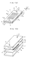
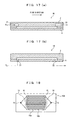
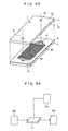
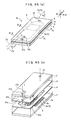
- Fig. 1(a) is a diagrammatic assembled
perspective view of an analytical chip according to
the first embodiment of the present invention, and
Fig. 1(b) is a diagrammatic exploded perspective
view of the analytical chip according to the first
embodiment of the present invention;
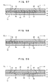
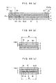
- Fig. 2(a) is a diagrammatic sectional view
taken on line Y-Y of Fig. 1(a), Fig. 2(b) is a
diagrammatic sectional view taken on line X1-X1 of
Fig. 1(a), and Fig. 2(c) is a diagrammatic sectional
view taken on line X2-X2 of Fig. 1(a);
- Fig. 3(a) is a diagrammatic top view of a
cover member of the analytical chip according to the
first embodiment of the present invention, Fig. 3(b)
is a diagrammatic top view of an intermediate plate
of the analytical chip according to the first
embodiment of the present invention, Fig. 3(c) is a
diagrammatic top view of an intermediate plate of
the analytical chip according to the first
embodiment of the present invention, and Fig. 3(d)
is a top view of a basal plate of the analytical
chip according to the first embodiment of the
present invention;
- Fig. 4 is a diagram of assistance in
explaining the definition of a flow direction of the
fluid sample;
- Fig. 5 is a diagrammatic top view of
assistance in explaining a method of making an
analytical chip according to the first and eleventh
embodiments of the present invention;
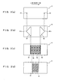
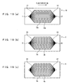
- Fig. 6(a) is a plan view diagrammatically
showing a conventional flow channel formed in a
sheet-shaped space, and Fig. 6(b) is a plan view
diagrammatically showing a slit-form flow channel of
analytical chips according to the first, eleventh,
and thirteenth embodiments of the present invention;
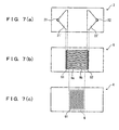
- Fig. 7(a) is a diagrammatic bottom view of a
cover member according to the first modification of
the first embodiment of the present invention, Fig.
7(b) is a diagrammatic top view of an intermediate
plate according to the first modification of the
first embodiment of the present invention, and Fig.
7(c) is a diagrammatic top view of a basal plate
according to the first modification of the first
embodiment of the present invention;
- Fig. 8(a) is a diagrammatic bottom view of a
cover member of the second modification of the first
embodiment of the present invention, and Fig. 8(b)
is a diagrammatic top view of a basal plate
according to the second modification of the first
embodiment of the present invention;
- Fig. 9(a) is a diagrammatic top view of a
cover member according to the third modification of
the first embodiment of the present invention, Fig.
9(b) is a diagrammatic top view of an intermediate
plate according to the third modification of the
first embodiment of the present invention, and Fig.
9(c) is a diagrammatic top view of a basal plate
according to the third modification of the first
embodiment of the present invention;
- Fig. 10 is a diagrammatic perspective view of
a whole constitution of an SPR sensor according to
the second embodiment of the present invention;
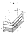
- Fig. 11 is a diagrammatic exploded perspective
view of the constitution of an analytical chip
according to the second embodiment of the present
invention;
- Fig. 12(a) is a diagrammatic assembled
perspective view of an analytical chip according to
the third embodiment of the present invention, and
Fig. 12(b) is a diagrammatic exploded perspective
view of the analytical chip according to the third
embodiment of the present invention;
- Fig. 13 is a diagrammatic bottom view of an
intermediate plate provided in the analytical chip
according to the third embodiment of the present
invention;
- Fig. 14(a) is a diagrammatic sectional view
taken on line Y1-Y1 of Fig. 12(a), and Fig. 14(b) is
a diagrammatic sectional view taken on line X3-X3 of
Fig. 12(a);
- Fig. 15(a) is a diagrammatic bottom view of a
cover member of an analytical chip according to the
first modification of the third embodiment of the
present invention, and Fig. 15(b) is a diagrammatic
top view of a basal plate of the analytical chip
according to the first modification of the third
embodiment of the present invention;
- Fig. 16(a) is a diagrammatic bottom view of a
cover member of the analytical chip according to the
second modification of the third embodiment of the
present invention, and Fig. 16(b) is a diagrammatic
top view of a basal plate of the analytical chip
according to the second modification of the third
embodiment of the present invention;
- Fig. 17(a), Fig. 17(b) are diagrammatic
sectional views of analytical chips according to the
third modification of the third embodiment of the
present invention;
- Fig. 18 is a diagrammatic bottom view of a
modification of the intermediate plate according to
the third embodiment of the present invention;
- Fig. 19(a) is a diagrammatic bottom view of an
intermediate plate according to the fourth
embodiment of the present invention, Fig. 19(b) is a
diagrammatic bottom view of a cover member according
to the fourth embodiment of the present invention,
and Fig. 19(c) is a diagrammatic top view of a basal
plate according to the fourth embodiment of the
present invention;
- Fig. 20(a) is a diagrammatic bottom view of an
intermediate plate according to the fifth embodiment
of the present invention, Fig. 20(b) is an enlarged
view of the part designated by XXb in Fig. 20(a),
and Fig. 20(c) is an enlarged view of the
substantial part of a conventional plate;
- Fig. 21(a) is a diagrammatic sectional view of
a part of the flow channel where the partition walls
is formed in the analytical chip according to the
sixth embodiment of the present invention, being
taken along a plane orthogonal to the width
directions of the flow channel, and Fig. 21(b) is an
enlarged view of the part designated by XXIb in Fig.
21(a);
- Fig. 22 is a diagrammatic bottom view of
intermediate plate according to the seventh
embodiment of the present invention;
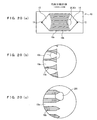
- Fig. 23(a), Fig. 23(b) are diagrams of
assistance in explaining the seventh embodiment of
the present invention;
- Fig. 24 is a diagrammatic bottom view of
intermediate plate according to the first
modification of the seventh embodiment of the
present invention;
- Fig. 25 is a diagrammatic bottom view of
intermediate plate according to the second
modification of the seventh embodiment of the
present invention;
- Fig. 26(a), Fig. 26(b), Fig. 26(c) are
diagrammatic bottom views intermediate plate
according to the third through fifth modifications
of the seventh embodiment of the present invention;
- Fig. 27 is a diagrammatic perspective view of
an analytical-chip unit according to the eighth
embodiment of the present invention;
- Fig. 28 is a diagrammatic perspective view of
an analytical-chip unit according to a modification
of the eighth embodiment of the present invention;
- Fig. 29 is a diagrammatic plan view of
assistance in explaining an analytical-chip unit
according to the ninth embodiment of the present
invention;
- Fig. 30 is a diagrammatic view of assistance
in explaining an analysis apparatus according to the
tenth embodiment of the present invention;
- Fig. 31 is a diagrammatic view of assistance
in explaining an analysis apparatus according to a
modification of the tenth embodiment of the present
invention;
- Fig. 32(a) is a diagrammatic top view of a
cover member according to an embodiment of the
present invention, Fig. 32(b) is a diagrammatic top
view of a first plate according to an embodiment of
the present invention, Fig. 32(c) is a diagrammatic
top view of a second plate according to an
embodiment of the present invention, and Fig. 32(d)
is a diagrammatic top view of basal plate according
to an embodiment of the present invention;
- Fig. 33(a) is a diagrammatic exploded
perspective view of an analytical chip according to
an embodiment of the present invention, and Fig.
33(b) is a diagrammatic sectional view of
substantial part of an analytical chip according to
an embodiment of the present invention, being taken
along a plane orthogonal to the flow direction of
the flow channel;
- Fig. 34 is a diagrammatic assembled
perspective view of an analytical chip according to
an embodiment of the present invention;
- Fig. 35(a) through Fig. 35(f) are diagrammatic
views of assistance in explaining an example of a
flow channel of an analytical chip according to the
present invention;
- Fig. 36(a), Fig. 36(b) are diagrammatic views
of assistance in explaining a conventional
analytical chip;
- Fig. 37 is a diagrammatic view of assistance
in explaining a conventional analytical chip;
- Fig. 38(a), Fig. 38(b) are diagrammatic views
of assistance in explaining a conventional
analytical chip;
- Fig. 39(a), Fig. 39(b) are diagrammatic views
of assistance in explaining a conventional
analytical chip;
- Fig. 40 is a diagram of assistance in
explaining running ahead of the fluid sample;
- Fig. 41 is a diagram of assistance in
explaining a constitution of the flow channel for
preventing the running ahead of the fluid sample;
- Fig. 42 is a diagram of assistance in
explaining a constitution of the flow channel for
preventing the running ahead of the fluid sample;
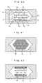
- Fig. 43 is a transverse sectional view of a
flow channel for assistance in explaining a
constitution of the flow channel for preventing the
running ahead of the fluid sample;
- Fig. 44 is a diagram of assistance in
explaining a constitution of the flow channel for
preventing the running ahead of the fluid sample;
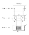
- Fig. 45(a) is a diagrammatic top view of a
cover member according to a modification the first
embodiment of the present invention, Fig. 45(b) is a
diagrammatic top view of a plate according to a
modification of the first embodiment of the present
invention, and Fig. 45(c) is a diagrammatic top view
of a basal plate according to a modification of the
first embodiment of the present invention;
- Fig. 46 is a diagram of assistance in
explaining an experimental embodiment of the present
invention;
- Fig. 47 is a diagram of assistance in
explaining an experimental embodiment of the present
invention;
- Fig. 48 is a block diagram illustrating an SPR
sensor system using an analytical chip according to
the eleventh embodiment of the present invention,
the analytical chip being partially broken away;
- Fig. 49 is a diagrammatic exploded perspective
view of an analytical chip according to the eleventh
embodiment of the present invention, a cover member
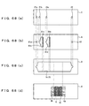
of the analytical chip being partially broken away;
- Fig. 50(a) is a diagrammatic sectional view
taken on line Y-Y of Fig. 48, Fig. 50(b) is a
diagrammatic sectional view taken on line X1-X1 of
Fig. 48, Fig. 50(c) is a diagrammatic sectional view
taken on line X2-X2 of Fig. 48, and Fig. 50(d) is an
enlarged view of the part designated by Ld in Fig.
50(a);
- Fig. 51(a) is a diagrammatic top view of a
cover member of an analytical chip according to the
eleventh embodiment of the present invention, Fig.
51(b) is a diagrammatic bottom view of a first plate
of an analytical chip according to the eleventh
embodiment of the present invention, Fig. 51(c) is a
diagrammatic top view of a second plate of an
analytical chip according to the eleventh embodiment
of the present invention, and Fig. 51(d) is a
diagrammatic top view of a basal plate of an
analytical chip according to the eleventh embodiment
of the present invention;
- Fig. 52(a) is a diagrammatic bottom view of a
cover member according to the first modification of
the eleventh embodiment of the present invention,
Fig. 52(b) is a diagrammatic top view of an
intermediate plate according to the first
modification of the eleventh embodiment of the
present invention, and Fig. 52(c) is a diagrammatic
top view of a basal plate according to the first
modification of the eleventh embodiment of the
present invention;
- Fig. 53(a) is a diagrammatic bottom view of a
cover member according to the second modification of
the eleventh embodiment of the present invention,
and Fig. 53(b) is a diagrammatic top view of a basal
plate according to the second modification of the
eleventh embodiment of the present invention;
- Fig. 54(a) is a diagrammatic top view of a
cover member according to the third modification of
the eleventh embodiment of the present invention,
Fig. 54(b) is a diagrammatic top view of an
intermediate plate according to the third
modification of the eleventh embodiment of the
present invention, and Fig. 54(c) is a diagrammatic
top view of a basal plate according to the third
modification of the eleventh embodiment of the
present invention;
- Fig. 55 is a diagrammatic exploded perspective
view of an analytical chip according to an
embodiment of the present invention;
- Fig. 56 is a diagram of assistance in
explaining an analysis apparatus according to the
twelfth embodiment of the present invention;
- Fig. 57 is a diagrammatic sectional view of
assistance in explaining the first modification of
the twelfth embodiment of the present invention;
- Fig. 58 is a diagrammatic sectional view of
assistance in explaining the second modification of
the twelfth embodiment of the present invention;
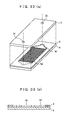
- Fig. 59 is a diagrammatic sectional view of
assistance in explaining the third modification the
twelfth embodiment of the present invention;
- Fig. 60 is a diagrammatic sectional view of
assistance in explaining another embodiment of the
present invention;
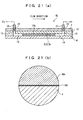
- Fig. 61 is a diagrammatic sectional view of
assistance in explaining another embodiment of the
present invention, whose substantial part is shown
with enlarged;
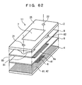
- Fig. 62 is a diagrammatic exploded perspective
view of an analytical chip according to another
embodiment of the present invention;
- Fig. 63 is a diagrammatic perspective view of
an analytical chip according to another embodiment
of the present invention;
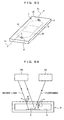
- Fig. 64 is a diagram of assistance in
explaining an example of the conventional
fluorescence analysis;
- Fig. 65(a) is a diagrammatic assembled
perspective view of an analytical chip according to
the thirteenth embodiment of the present invention,
and Fig. 65(b) is a diagrammatic exploded
perspective view of an analytical chip according to
the thirteenth embodiment of the present invention;
- Fig. 66(a) is a diagrammatic sectional view
taken on line Y-Y of Fig. 65(a), Fig. 66(b) is a
diagrammatic sectional view taken on line X1-X1 of
Fig. 65(a), and Fig. 66(c) is a diagrammatic
sectional view taken on line X2-X2 of Fig. 65(a);
- Fig. 67(a) is a diagrammatic top view of a
cover member of an analytical chip according to the
thirteenth embodiment of the present invention, Fig.
67(b) is a diagrammatic top view of a plate of an
analytical chip according to the thirteenth
embodiment of the present invention, Fig. 67(c) is a
diagrammatic top view of a plate of an analytical
chip according to the thirteenth embodiment of the
present invention, and Fig. 67(d) is a diagrammatic
top view of a basal plate of an analytical chip
according to the thirteenth embodiment of the
present invention;
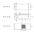
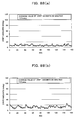
- Fig. 68(a) is a diagrammatic top view of a
cover member of an analytical chip according to the
thirteenth embodiment of the present invention, Fig.
68(b) is a diagrammatic top view of a plate of an
analytical chip according to the thirteenth
embodiment of the present invention, Fig. 68(c) is a
diagrammatic top view of a plate of an analytical
chip according to the thirteenth embodiment of the
present invention, and Fig. 68(d) is a diagrammatic
top view of a basal plate of an analytical chip
according to the thirteenth embodiment of the
present invention;
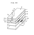
- Fig. 69 is a diagrammatic exploded perspective
view of an analytical chip according to the second
modification of the thirteenth embodiment of the
present invention;
- Fig. 70(a) is a diagrammatic top view of a
cover member of an analytical chip according to the
second modification of the thirteenth embodiment of
the present invention, Fig. 70(b) is a diagrammatic
top view of a plate of an analytical chip according
to the second modification of the thirteenth
embodiment of the present invention, Fig. 70(c) is a
diagrammatic top view of a plate of an analytical
chip according to the second modification of the
thirteenth embodiment of the present invention, Fig.
70(d) is a diagrammatic top view of a plate of an
analytical chip according to the second modification
of the thirteenth embodiment of the present
invention, and Fig. 70(e) is a diagrammatic top view
of a basal plate of an analytical chip according to
the second modification of the thirteenth embodiment
of the present invention;
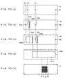
- Fig. 71(a) is a diagrammatic top view of a
plate of an analytical chip according to the third
modification of the thirteenth embodiment of the
present invention, and Fig. 71(b) is a diagrammatic
top view of a plate of an analytical chip according
to the fourth modification of the thirteenth
embodiment of the present invention;
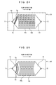
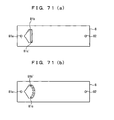
- Fig. 72 is a diagrammatic perspective view
showing the whole constitution of an SPR sensor
according to the fourteenth embodiment of the
present invention;
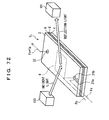
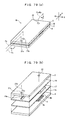
- Fig. 73 is a diagrammatic exploded perspective
view showing the constitution of an analytical chip
according to the fourteenth embodiment of the
present invention;
- Fig. 74(a) is a diagrammatic assembled
perspective view of an analytical chip according to
the fifteenth embodiment of the present invention,
and Fig. 74(b) is a diagrammatic exploded
perspective view of an analytical chip according to
the fifteenth embodiment of the present invention;
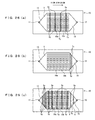
- Fig. 75 is a diagrammatic sectional view taken
on line Y-Y of Fig. 74(a), illustrating an
analytical chip according to the fifteenth
embodiment of the present invention;
- Fig. 76(a) is a diagrammatic top view of a
cover member of an analytical chip according to the
fifteenth embodiment of the present invention, Fig.
76(b) is a diagrammatic top view of a plate of an
analytical chip according to the fifteenth
embodiment of the present invention, and Fig. 76(c)
is a diagrammatic top view of a basal plate of an
analytical chip according to the fifteenth
embodiment of the present invention;
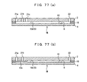
- Fig. 77(a) is a diagrammatic sectional view of
an analytical chip according to the first
modification of the fifteenth embodiment of the
present invention, and Fig. 77(b) is a diagrammatic
sectional view of an analytical chip according to
the second modification of the third embodiment of
the present invention;
- Fig. 78(a) is a diagrammatic top view of a
cover member of an analytical chip according to the
third modification of the fifteenth embodiment of
the present invention, Fig. 78(b) is a diagrammatic
top view of a plate of an analytical chip according
to the third modification of the fifteenth
embodiment of the present invention, and Fig. 78(c)
is a diagrammatic top view of a basal plate of an
analytical chip according to the third modification
of the fifteenth embodiment of the present
invention;
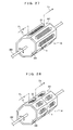
- Fig. 79(a) is a diagrammatic assembled
perspective view of an analytical chip according to
the sixteenth embodiment of the present invention,
Fig. 79(b) is a diagrammatic exploded perspective
view of an analytical chip according to the
sixteenth embodiment of the present invention;
- Fig. 80 is a diagrammatic sectional view taken
on line Y-Y of Fig. 79(a), showing an analytical
chip according to the sixteenth embodiment of the
present invention;
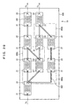
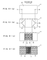
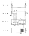
- Fig. 81(a) is a diagrammatic top view of a
cover member of an analytical chip according to the
sixteenth embodiment of the present invention, Fig.
81(b) is a diagrammatic top view of a plate of an
analytical chip according to the sixteenth
embodiment of the present invention, Fig. 81(c) is a
diagrammatic top view of a plate of an analytical
chip according to the sixteenth embodiment of the
present invention, and Fig. 81(d) is a diagrammatic
top view of a basal plate of an analytical chip
according to the sixteenth embodiment of the present
invention;
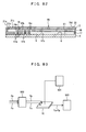
- Fig. 82 is a diagrammatic sectional view of an
analytical chip according to a modification of the
sixteenth embodiment of the present invention;
- Fig. 83 is a diagram of assistance in
explaining an analysis apparatus according to the
seventeenth embodiment of the present invention;
- Fig. 84 is a diagram showing another
embodiment of the present invention;
- Fig. 85 is a diagram showing another
embodiment of the present invention;
- Fig. 86(a), Fig. 86(b) are sectional views of
assistance in explaining the diffusion of fluid in
the flow channel;
- Fig. 87(a) is a sectional view of assistance
in explaining the diffusion in the flow channel of a
modification of the fifteenth embodiment of the
present invention, and Fig. 87(b) is a sectional
view of the flow channel shown from the side of the
cover member; and
- Fig. 88(a) is a graph showing the results of
an experimental embodiment of the present invention,
and Fig. 88(b) is a graph showing the results using
a conventional analytical chip.
-
Best Mode for Carrying Out the Invention
-
Preferred embodiments of the present invention
will be described hereinafter with reference to the
drawings. Throughout the following embodiments,
description will be given on the assumption that a
fluid sample being the target for analysis is water-soluble
(or hydrophilic, provided that the solvent
is water). It is a matter of course, however, that
even if the fluid sample is hydrophobic, it can be
analyzed using an analytical chip according the
present invention in a similar manner. Further, the
fluid sample of the present invention is to contain
one or more substances that can cause any
interaction such as antigen-antibody reaction,
complementary DNA binding, receptor-ligand
interaction, or enzyme-substrate interaction.
Specifically, the sample is selectable from various
liquids (and disperse systems, such as suspensions
and colloids) that contain (or may contain) one or
more target substances for measurement, for example,
protein, nucleic acid, DNA, RNA, PNA, peptide,
hormone, antigen, antibody, ligand, receptor,
enzyme, substrate, low molecular organic compound,
cell, ion, etc., and complex thereof. These target
substances may be labeled, if necessary, with any
other substance such as a fluorescence substance, a
luminescence substance, a radioactive substance,
etc.
-
Moreover, the term light of the present
invention does not limitedly mean light in the
visible region, unless otherwise indicated, but may
be include non-visible light in the long-wavelength
region or the short-wavelength region, such as
ultraviolet rays, infrared rays, and X-rays.
-
In the following description, like or
corresponding components are designated by like
reference characters throughout the drawings.
(1) First Embodiment
-
Figs. 1-3 show analytical chip according to
the first embodiment of the present invention.
Specifically, Fig. 1(a) is a diagrammatic assembled
perspective view of the chip, Fig. 1(b) is a
diagrammatic exploded perspective view of the chip,
Fig. 2(a) is a sectional view taken along line Y-Y
of Fig. 1(a), Fig. 2(b) is a sectional view taken
along line X1-X1 of Fig. 1(a), Fig. 2(c) is a
sectional view taken along line X2-X2 of Fig. 1(a),
Fig. 3(a) is a top view of the cover member of the
chip, Fig. 3(b) is a top view of the first plate of
the chip, Fig. 3(c) is a top view of the second
plate of the chip, and Fig. 3(d) is a top view of
the basal plate of the chip. In the following
description, flow direction A of fluid sample Fs is
defined as the major direction in which most of the
fluid sample Fs flows through the flow channel. To
take Fig. 4 as an example, the flow direction of
flow channel 5' is defined as the direction
indicated by the arrow in solid line.
-
As shown in Figs. 1(a), (b), the present
analytical chip (hereinafter called simply "the
chip") 1 is composed of cover member 2, which is
flat-plate shaped, first plate (hereinafter called
simply "the plate") 8, which is of small thickness,
second plate (an intermediate plate, hereinafter
called simply "the plate") 9, which is of small
thickness as with the plate 8, and basal plate 4.
In carrying out analysis, as shown in Fig. 1(a),
these components 2, 8, 9, 4 are piled in the listed
order from above downward, and fastened together as
a unit by a joining holder, not shown in the
drawings. The plates 8, 9 are thus interposed
between the cover member 2 and the basal plate 4.
-
It is preferable that the holder has a
protection device for securing accurate alignment
and preventing scratches. Examples of the
protection device include a locking part, attached
to the holder so as to lock the analytical chip 1,
and a hollow, formed on the holder so that an
observation part (reaction area 6, which will be
described later) of the analytical chip 1 does not
touch the holder.
-
As shown in Fig. 2(a), fluid sample Fs is to
be injected into opening 21 (an injection port at
the upstream end of flow channel 5, which will be
described later) of the cover member 2, and to flow
through opening 81 (a flow-channel confluence part
on the upstream side) of the plate 8, then through
each of slit-form openings 9a (inner flow channels)
of the plate 9. Subsequently, the fluid sample Fs
is to flow through opening 82 (a flow-channel
confluence part on the downstream side) of the plate
8, and to be finally drained from opening 22 (a
drain port at the downstream end of flow channel 5,
which will be described later) of the cover member
2. While passing through the slit-form openings 9a
of the plate 9, the fluid sample Fs is to be in
contact with one or more specific substances 61,
which are fixed to reaction area 6 of the basal
plate 4.
-
The fluid sample Fs is to flow through the
flow channel 5, whose section (orthogonal to the
flow direction A of the fluid sample Fs) is in a
slit shape elongated horizontally, as shown in Figs.
2(b), (c). Put another way, the flow channel 5 is
formed as a sheet-shaped space having closed-section
structure.
-
In the present invention, the "flow channel
formed as a sheet-shaped space" generally means a
flow channel whose long side 5a has a size W of
between 500 µm and 100 mm inclusive, and whose short
side 5b has a size H of between 5 µm and 2 mm
inclusive. The "long side" means the longest side
among all the sides of both sections orthogonal to
the flow direction of the flow channel 5 and
sections orthogonal to width directions, generally
being a side along either the width of the flow
channel 5 or the length of the flow channel 5 in the
flow direction (in the present embodiment, a side
along the width of the flow channel 5). The "short
side" means a side along the height of flow channel
5. The size ratio between the long side 5a and the
short side 5b (= [long side size W]/[short side size
H]) is generally 1.5 or above, preferably 10 or
above, and generally 20000 or below, preferably 100
or below. When the flow channel 5 is, as will be
described later, divided into two or more inner flow
channels 9a with one or more partition walls 9b
(which serve as projection member, partition
members, or prop members), at least the sizes of the
whole flow channel 5 (the sizes of the whole of the
plural inner flow channels 9a joined together) have
to meet the above range of size ratio. In the
present embodiment, the length W of the long side 5a
is set at 20 mm, while the length of the short side
5b of each of the plates 8, 9 (in X1-X1 section,
thickness H1 of the plate 8; in X2-X2 section,
thickness H2 of the plate 9) is set at 250 µm.
-
Also, the "closed-section structure" means
that the flow channel's section orthogonal to the
flow direction of the flow channel 5 is in a closed
shape. The flow channel 5 is regarded to having
closed-section structure even when the bottom face,
the ceiling surface, the wall surface, etc. of the
flow channel 5 are made of a porous material having
minute pores, such as a membrane filter or a gas-permeable
membrane, as long as the fluid sample Fs
flowing through the flow channel 5 does not pass
through the minute pores during analysis. The
descriptions in the present specification are made
on the assumption that, unless otherwise indicated,
the flow channel 5 is formed as a sheet-shaped space
having closed-section structure.
-
Hereafter, each of the above components of the
present analytical chip 1 will be described in
detail.
-
Each of the cover member 2, the plate 8, the
plate 9, and the basal plate 4 can be made from any
kinds of materials, examples of which include, but
are not limited to, resins, ceramics, glasses, and
metals. However, when measuring any interaction
(such as reaction or binding) between target species
and the specific substances 61 optically based on
fluorescence, luminescence, color change, or
phosphorescence, etc., it is desired to make each of
the cover member 2 and the plates 8, 9 from one or
more transparent materials; as an exception, when
measurement can be carried out with the analytical
chip 1 being disassembled, the cover member 2 and
the plates 8, 9 are not necessarily required to have
transparency. Examples of transparent materials
are: resins, such as acrylic resin, polycarbonate,
polystyrene, polydimethylsiloxane, and polyolefin;
and glasses, such as PyrexR (i.e., borosilicate
glass) and quartz glass.
-
In the present embodiment, it is allowed to
make the analytical chip 1 using low-strength
materials (whose Young's modulus is 1 GPa or above
and 60 GPa or below), because the deformation of the
chip can be prevented by adopting such an
arrangement as will be described later. Still,
making the analytical chip 1 from high-strength
materials enables analysis with higher precision.
It is therefore preferable to make the components of
the analytical chip 1, namely the cover member 2,
the plate 8, the plate 9, and the basal plate 4,
from one or more high-strength materials.
Specifically, each of the cover member 2, the plate
8, the plate 9, and the basal plate 4 is made from
at least one material whose Young's modulus is
preferably 60 GPa or more. In the embodiment, it is
assumed that every component of the analytical chip
1 is made from a strong material whose Young's
modulus is 60 GPa or more.
-
As shown in Fig. 3(a), opening (injection
port) 21 is formed at the upstream end of the cover
member 2, while another opening (drain port) 22 is
formed at the downstream end of the cover member 2.
-
The injection port 21 is connected to an
injection pump (e.g. syringe pump) using a connector
and a tube (not shown in the drawings), while the
drain port 22 is connected to a waste liquid tank
using a connector and a tube (not shown in the
drawings). Operating the above injection pump, it
is possible to inject the fluid sample Fs via the
injection port 21 into the chip 1 and drain it from
the chip 1.
-
As shown in Fig. 3(b), opening 81 is formed at
the upstream side of the plate 8, while opening 82
is formed at the downstream side of the plate 8.
-
The upstream end 81x of the opening 81 is
located in such a manner as to be aligned, and
communicate, with the injection port 21 of the cover
member 2 when the chip 1 is in the assembled state.
The opening 81 is also formed in such a manner that
its width gradually becomes broader from the
upstream end 81x along the flow direction toward a
middle part of the plate 8 (toward the downstream
side along the flow direction of the fluid sample
Fs).
-
On the other hand, the downstream end 82x of
the opening 82 is located in such a manner as to be
aligned, and communicate, with the drain port 22 of
the cover member 2 when the chip 1 is in the
assembled state. The opening 82 is also formed in
such a manner that its width gradually becomes
narrower from the middle part of the plate 8 along
the flow direction toward the downstream end 82x
(toward the downstream side along the flow direction
of the fluid sample Fs).
-
When the chip 1 is in the assembled state, the
top and under faces of the plate 8 are blocked by
the cover member 2 and the plate 9, respectively,
and each of the openings 81, 82 forms a part of the
flow channel in which the fluid sample Fs flows
unitedly. The part of the flow channel, formed by
each the openings 81, 82 of the plate 8, is also
called flow- channel confluence part 81, 82.
Although in Figs. 1(a) and 2(a), (b) the whole top
surface and the whole under surface of the plate 8
are blocked by the cover member 2 and the plate 9,
respectively, yet it is allowable that at least the
parts of the top and under surfaces of the plate 8
corresponding to the openings 81, 82 is blocked.
-
As shown in Fig. 3(c), around the middle part
of the plate 9 along the flow direction, projection
member is formed as one or more partition walls
(partition members) 9b, dividing two or more slit-form
openings (or inner openings. hereinafter
called the slit-form openings) 9a one from another
across the width directions. When the chip 1 is in
the assembled state, the slit-form openings 9a form
slit-form inner flow channels (hereinafter also
called slit-form flow channels), which are divided
with the partition walls 9b one from another around
the middle part of the flow channel 5. The term
"inner flow channels" means flow channels that are
divided with the partition members across the width
directions. The partition walls 9b adjoin directly
the basal plate 4 and the plate 8 so that the fluid
sample Fs is shut out from both between the
partition walls 9b and the basal plate 4 and between
the partition walls 9b and the plate 8, thereby the
flow channel 5 being divided into plural inner flow
channels. Meanwhile, when the chip 1 is in the
assembled state, the top and under faces of the
slit-form openings are blocked by the plate 8 and
the basal plate 4 to thereby define the slit-form
flow channels. Since the slit-form openings, the
slit-form flow channels, and the inner flow channels
are thus equivalent to each other, they are all
designated by the same reference character 9a.
-
It is usually preferable to form each of the
slit-form flow channels 9a such that its cross
section has an aspect ratio {[length size]/[width
size]} of between 0.005 (e.g., 5 µm in length and 1
mm in width) and 100 (e.g., 10 mm in length and 100
µm in width) inclusive. Also, it is generally
preferred that each of the slit-form flow channels
9a has a cross sectional area of 5mm2 or below.
Specifically, the sectional area of each slit-form
flow channel 9a is usually 100 µm2 or above,
preferably 2000 µm2 or above, and usually 5 mm2 or
below, preferably 0.3 mm2 or below.
-
Also, when the chip 1 is in the assembled
state, the upstream end 91 of each slit-form opening
9a is located such as to communicate with the
downstream end of the opening 81 of the plate 8,
while the downstream end 92 of each slit-form
opening 9a is located such as to communicate with
the upstream end of the opening 82 of the plate 8.
-
With the above arrangement, the fluid sample
Fs injected from the flow-channel confluence part 81
of the plate 8 flows through the upstream end 91 of
each slit-form flow channel 9a into each slit-form
flow channel 9a of the plate 9, finally going out of
the downstream end 92 of each slit-form flow channel
9a to gather into one volume in the flow-channel
confluence part 82 of the plate 8.
-
According to the present analytical chip 1 as
described above, it becomes possible to prevent
running ahead of the fluid sample Fs by providing
the conventionally-formed, sheet-shaped flow channel
5 with one or more partition walls 9b to divide the
flow channel 5 into two or more inner flow channels
9a with minute section (namely, by decreasing the
cross sectional area of the individual flow
channel).
-
In the meanwhile, as shown in Figs. 1(a), (b),
reaction area 6 is disposed around the middle part
of the basal plate 4 along the flow direction so as
to face the flow channel 5.
-
Illustrated in a simplified form in Figs.
1(a), (b), the reaction area 6 is an area where, as
shown in Fig. 3(d), at least one specific substance
61 that can cause interaction specifically or
nonspecifically with one or more predetermined
substances (target species) is fixed, as plural
spots, to the surface of the basal plate 4 on the
side of the flow channel 5. In order to fix the
specific substance 61 securely to the basal plate 4,
it is preferable to previously form on the surface
of the basal plate 4 an immobilized film (organic
film) that can bind with the specific substance 61.
-
The sizes {[length size] × [width size]} of
the reaction area 6 are usually between 3 mm × 3 mm
through 20 mm × 20 mm inclusive. In the area, the
specific substance 61 are disposed as generally 9
through 40000 spots in such a matrix that 3 through
200 spots are aligned along every row of each
direction at intervals of between 100 µm and 1 mm
inclusive.
-
It is assumed that as the specific substance
61, the embodiment uses plural kinds of specific
substances (different from each other) each of which
can cause any interaction, such as reaction or
binding, specifically or nonspecifically with
different kinds of substances.
-
Each of the predetermined substance and the
specific substance can be selected from substances
that can cause any interaction, such as antigen-antibody
reaction, complementary DNA binding,
receptor-ligand interaction, enzyme-substrate
interaction, etc., and is selectable from various
substances, for examples, protein, nucleic acid,
DNA, RNA, PNA, peptide, hormone, antigen, antibody,
ligand, receptor, enzyme, substrate, low molecular
organic compound, cell, etc., and complex thereof.
These substances may be labeled, if necessary, with
any other substance such as a fluorescence
substance, luminescence substance, radioactive
substance, etc.
-
Meanwhile, the following point is to be noted
(although it is restated in the description of the
production method of the present analytical chip 1,
as will be described later). When the present
analytical chip 1 is assembled, the plate 9 is first
fixed on the basal plate 4, after which the specific
substances 61 are fixed to the basal plate 4 from
above the plate 9 through the slit-form openings 9a
of the plate 9. Hence, the reaction area 6 (the
area where the plural specific substances 61 are
fixed) shown in Fig. 3(d) is not actually formed in
the early stage of assembling: in Fig. 3(d), the
specific substances 61 fixed to the basal plate 4
are illustrated for convenience in explaining the
arrangement of the spots of the specific substances
61 with respect to the basal plate 4 intelligibly.
Accordingly, Fig. 3(d) illustrates the positions and
the number of the spots of the specific substances
61 along the width directions in such a manner that
they correspond to the positions and the number of
the slit-form openings 9a of the intermediate plate
9 along the width directions.
-
The fluid sample Fs flowing through the slit-form
flow channels 9a comes into contact with these
specific substances 61 during the process of the
flowing, after which analysis is carried out
regarding the fluid sample Fs, based on the state of
reaction at each spot of the specific substances 61.
-
Specifically, if the occurrence of reaction is
detected at any spot of the specific substances 61,
it is possible to determine that the fluid sample Fs
contains a kind of substance corresponding to the
specific substance 61 fixed at the spot where the
reaction is detected.
-
The specific substances 61 are fixed to the
chip 1 as plural spots arranged at regular intervals
so as not to be contaminated with the specific
substance 61 at the neighboring spots. The term
"regular intervals" means the intervals between the
centers of the spots where the specific substances
are fixed, to which intervals the pitch of the
partition walls 9b is set to be substantially
identical. In the present invention, it is not
necessary to reduce the number of spots of the
specific substance 61 per unit area than in the
conventional chip in return for disposing the
partition walls 9b; on the contrary, since the
disposition of the partition walls 9b enables to
prevent the contamination as described above, the
pitch of the specific substances 61 along the width
directions (the directions orthogonal to the flow
direction) can be minimized, so that it becomes
possible to rather increase the number of spots per
unit area.
-
It is not necessary to use different kinds of
specific substances 61 at different spots; the same
specific substance 61 can be used at two or more
different spots. In any event, what kinds of
specific substances 61 are used should be determined
as appropriate, depending on the object of analysis.
-
The following description is made on a
production method of the present analytical chip 1.
The plate 9 is bonded to the basal plate 4, after
which the specific substance 61 is fixed to the
basal plate 4. Specifically, the specific substance
61 is dispersed or dissolved in a liquid to form a
dispersion liquid or solution of the specific
substance 61. The dispersion liquid or solution is
dripped through the slit-form openings 9a of the
plate 9 in such a manner that the drops are aligned
at regular intervals, as shown in Fig. 5, using a
injector or a spotter (not shown in the drawings)
that is capable of positioning operation. In the
following description, the above dispersion liquid
or solution, which is obtained by dispersing or
dissolving the specific substance 61 into a liquid,
is called the "fluid containing specific substance".
Although not limiting the kind of the liquid in
which the specific substance 61 is dispersed or
dissolved, it is assumed that in the present
embodiment, the fluid containing specific substance
is an aqueous solution obtained by dissolving the
specific substance 61 in water. Fig. 5 is a top
view of the chip, illustrating the state where the
plate 9 is bonded to the basal plate 4 and the fluid
containing specific substance is dripped so that the
specific substance 61 is fixed.
-
Subsequently, the plate 8 is mounted on the
plate 9, and the cover member 2 is further mounted
on the plate 8.
-
In the above production method of the present
analytical chip 1, it is preferable that the plate 9
is made of a material having lower affinity for the
fluid containing specific substance than that of the
basal plate 4. In the present embodiment, because
the fluid containing specific substance is the
aqueous solution of the specific substance 61, it is
preferable to use a material having hydrophobicity
as a preferred example of the member having lower
affinity. With this arrangement, the surface of the
plate 9 on the side of the plate 8 (the side
opposite to the basal plate 4) has a lower affinity
for the fluid containing specific substance than
that of the surface of the basal plate 4 on the side
of the flow channel 5. When dripping from an
injector the fluid containing specific substance, in
which the specific substance 61 is dispersed or
dissolved, there may arise the case where drops of
the fluid containing specific substance deviate from
the desired positions due to environmental
disturbances or equipment factors and fall over the
partition walls 9b of the plate 9. Even in such a
case, the fluid containing specific substance
spontaneously runs (namely, is guided) toward the
basal plate 4, which has a higher affinity for the
specific substance 61 than the plate 9, and is
guided securely onto the basal plate 4.
Consequently, it becomes possible to fix the
specific substance 61 correctly at target positions
on the basal plate 4.
-
It is also preferable to make only the
partition walls 9b of the plate 9 from a material
having a lower affinity for the fluid containing
specific substance than that of the basal plate 4,
or to form, on the surface of the partition walls 9b
of the plate 9, a layer having a lower affinity for
the fluid containing specific substance than that of
the basal plate 4. Also preferably, the plate 8 and
the cover member 2 can be bonded and joined together
as a unit.
-
Alternatively, it is also preferable to make
the surface of the plate 9 on the side of the plate
8 (the side opposite to the basal plate 4) from a
material having a lower affinity for the fluid
containing specific substance than the wall surface
of the slit-form openings 9a of the plate 9. With
this arrangement, as is the case described above,
even when the fluid containing specific substance
has fallen over the surface of the partition walls
9b of the plate 9 on the side of the plate 8, the
specific substance 61 runs toward the slit-form
openings 9a, which has a higher affinity for the
fluid containing specific substance than the surface
of the plate 9 opposite to the basal plate 4.
Consequently, the fluid containing specific
substance is guided securely onto the slit-form
openings 9a, so that it becomes possible to fix the
specific substance 61 correctly at target positions
on the basal plate 4.
-
In the present specification, the term
"affinity" of a certain substance means broadly a
property of tending to bind with or adsorb another
substance, and therefore should not be interpreted
as limitedly designating hydrophilicity or
hydrophobicity.
-
Besides, although in the present embodiment
the components are joined together by fastening
physically with a holder so that the chip 1 can be
disassembled, it is also possible to use any other
measures for joining the components. Examples of
the joining measures include, although not limited
thereto, adhesion with an adhesive agent, resin
bonding with a primer, diffusion bonding, anodic
bonding, eutectic bonding, heat sealing, ultrasonic
bonding, laser fusing, dissolution with a resolvent
or a solvent, etc. It is also possible to use a
sticky tape, an adhesive tape, or a self-adsorbent.
Alternatively, it is also preferable to adopt
pressure bonding, or form concavities and
convexities on the components so as to be engageable
with each other. With these measures, the
components can be easily assembled. It is also
allowable to use any two or more of the above
joining measures in combination.
-
Because the analytical chip according to the
first embodiment of the present invention is
constituted as described above, the fluid sample Fs
injected via the injection port 21 of the cover
member 2 flows into the flow-channel confluence part
81 of the plate 8, as shown in Figs. 2(a) and 3(a)-(d).
-
After then, the fluid sample Fs flows from the
upstream ends 91 of the slit-form flow channels 9a
into the individual slit-form flow channels 9a, and
comes into touch with the specific substance 61.
-
Subsequently, the flows of the fluid sample Fs
run out of the downstream ends 92 of the slit-form
flow channels 9a to join together in the flow-channel
confluence part 82 and be drained from the
drain port 22 of the cover member 2 toward outside
the chip 1.
-
As described above, according to the present
analytical chip 1, the plural slit-form flow
channels 9a share the single injection port 21 and
the single drain port 22. Hence, compared to the
above-described conventional technique, in which
plural flow channels are simply arranged in parallel
and the fluid is injected into and drained from each
of the flow channels separately, the present
analytical chip has the advantage that it needs
fewer connectors and tubes for injection and
drainage, simplifying the installation work of such
connectors and tubes to the chip 1.
-
Further, using the present analytical chip 1,
it becomes possible to make different kinds of fluid
samples Fs flow serially to measure them
successively. With this feature, there is no need
to prepare a different analytical chip 1 for each
kind of fluid sample Fs, so that analysis can be
carried out easily within a short time.
-
Furthermore, since the flow-channel confluence
part 81 becomes gradually broader from the upstream
end 81x toward the middle part along the flow
direction, the fluid sample Fs can be guided
smoothly toward the middle part of the flow
direction. On the other hand, since the flow-channel
confluence part 82 becomes gradually
narrower from the middle part toward the downstream
end 82x along the flow direction, the fluid sample
Fs can be guided smoothly toward the downstream end
82x.
-
Besides, using the present analytical chip 1,
it is possible to prevent the occurrence of air
bubbles due to enclosing flow of the fluid sample
Fs. The following description is given on the
advantage that the occurrence of air bubbles is
preventable compared with a conventional problem.
-
In the conventional microchannel chip, a fluid
sample is generally made flow into a flow channel
that is initially filled with gas (mostly air), so
that the interface between the three phases of
solid-gas-liquid arises to move on through the flow
channel. However, since the flow channel has a
cross section that is elongated along its width
directions, various trifle matters (non-uniformity
of wettability along the wall surface of the flow
channel, vibrations due to unstable equipment,
adhesion of foreign particles to the surface of the
flow channel, etc.) may bring about the state shown
in Fig. 36(a): namely, the interface between the
three phases of solid-gas-liquid S (the front end of
the fluid sample Fs) becomes a non-linear, non-uniform
shape along the width directions B of the
flow channel, which is perpendicular to the flow
direction A.
-
Subsequent to the state shown in Fig. 36(a),
as the fluid sample Fs flows, a part of the
interface between the three phases of solid-gas-liquid
S runs ahead of the remaining part to
gradually spread out as indicated by arrow F and
finally, as shown in Fig. 36(b), completely encloses
a small amount of gas 200, thereby an air bubble 201
being produced in the fluid sample Fs. In addition,
in such a sheet-shaped flow channel as described
above, since such an air bubble 201 adjoins the wall
surface of the flow channel with a large interfacial
area, it is difficult to carry away and remove the
air bubble 201 toward the downstream direction by
keeping the fluid flowing, so that in many cases the
air bubble 201 remains dwelling.
-
Another conceivable idea is to apply high
pressure to inside the flow channel to thrust out
forcibly the air bubble 201 from the flow channel.
However, depending on the constitution of the
analytical chip, the materials of the analytical
chip, or the measures used for joining the
analytical chip, it may cause damage to the flow
channel due to acute increase of the pressure. As
long as the flow channel is made from a solid
material, the flow channel does not receive a
critical influence even when high pressure is
applied to the flow channel. Even if the flow
channel structure is made from a combination of
plural materials, as long as these materials are
strongly bonded together, the flow channel does not
receive a critical influence due to high pressure
applied to the flow channel. Also, even when piping
(tube) or a connector is joined to the flow channel,
as long as they are bound firmly to the flow
channel, the flow channel still does not receive a
critical influence due to high pressure applied to
the flow channel. However, under circumstances
where for some reason any restrictions are imposed
on the conditions applied to the analytical chip,
such as materials, measures for joining, piping
installation, etc., there are assumable cases where
it is undesirable to apply high pressure to inside
the flow channel to thrust out forcibly the air
bubble 201 from the flow channel. For example, when
the analytical chip needs be made from a combination
of plural materials, it is preferable that compared
to the combination of materials selected from
different material groups (for example, the
combination of a metal and a glass, the combination
of a resin and a glass, etc.), a combination of
materials selected from the same material group is
used in view of waste treatment. Further, in order
to reduce the weight of the analytical chip, it is
preferable that the analytical chip is made from a
lightweight material such as a resin. Also, when
using a processing method with high precision such
as injection molding or compression molding from the
viewpoint of formability, it is preferable that the
analytical chip is made from a resin. Further, in
the case where exposure to high-temperature
circumstances is assumed during the stage of
producing the analytical chip, the preliminary stage
toward the analysis using the analytical chip,
and/or the stage of analysis using the analytical
chip, it is preferable that the analytical chip is
made from a material such as a glass or a metal.
Thus, materials from which the analytical chip is
made should be selected as appropriate, according to
the demands of a designer, a manufacturer, a user,
etc.
-
When an air bubble 201 remains dwelling as
described above, there arise such defects as
illustrated by Figs. 37 through Figs. 39(a), (b).
-
For example, an air bubble 201 that remains
dwelling in the reaction area 204 can prevent, as
shown in Fig. 39(a), the specific substance fixed to
the reaction area 204 from coming into touch with
the fluid sample.
-
In addition, if an air bubble 201 remains
dwelling in the measurement area 205, as shown in
Fig. 39(b), accurate analysis can be prevented.
Especially when optical measurement is being carried
out while the air bubble 201 stays dwelling in the
measurement area 205, the measurement may become
even impossible. It is therefore necessary to
remove the fluid sample from the flow channel and
then carry out prearrangement again before resuming
the measurement, so that the efficiency of
analytical work is decreased markedly.
-
Besides, as shown in Fig. 37, particulate
substances 202 contained in the fluid sample Fs tend
to aggregate and be accumulated specifically around
the upstream side of the air bubble 201, thereby
exerting an influence upon the subsequent processes
such as flowing process, mixing process, and
reaction process.
-
In addition, when the air bubble 201 remains
dwelling to make the surrounding flow non-uniform,
as indicated by arrow G1 of Fig. 38(a), back-flow
arises in extreme cases between the upstream side of
the air bubble 201 and the flow channel wall
surface, occasionally exerting an influence upon
analysis. Further, at a constant pressure and a
constant velocity, the fluid sample Fs in the
vicinity of the air bubble 201 flows along the
exterior surface of the air bubble 201, as indicated
by arrow G2 of Fig. 38(b), and therefore runs faster
than the other.
-
Hence, in the reaction area 204 to which the
specific substance is fixed, the subarea 204a in the
vicinity of the air bubble 201 comes in touch with a
larger number of molecules in the fluid sample
(namely, is passed along by a larger volume of fluid
sample) than the other subarea. Consequently,
interactions proceed under various conditions
depending on the positions in the reaction area 204,
so that it is difficult to accurately analyze the
fluid sample based on the interactions occurring in
the reaction area 204, such as binding or
dissociation.
-
Furthermore, when an air bubble 201 remains
dwelling in the fluid sample, the difference of heat
transfer coefficient between the fluid sample Fs and
the air bubble 201 can bring about non-uniformity of
temperature in the system of measurement, thereby
exerting an influence upon the results of analysis.
-
By contrast, according to the analytical chip
1 of the present embodiment, since the flow channel
5 formed as a sheet-shaped space is divided into the
minute (narrow-width) inner flow channels (slit-form
flow channels) 9a with the partition walls 9b, it
becomes possible to prevent the occurrence of air
bubbles due to enclosing flow of the fluid sample
Fs.
-
Specifically speaking, in the conventional
sheet-shaped flow channel, since the interface
between the three phases of solid-gas-liquid has a
long front line as shown in Fig. 6(a), part of the
fluid sample Fs runs ahead due to non-uniformity of
wettability, so that enclosing flow of the fluid
sample Fs occurs to result in generation of the
enclosure of gas (air bubble 201). In the present
invention, since the flow channel 5 is divided into
the separate, minute inner flow channels (the slit-form
flow channels 9a), the length of line segment L
(flow channel width) perpendicular to the main flow
in the flow channel becomes small as shown in Fig.
6(b), so that the occurrence rate of the enclosing
flow decreases significantly. Besides, since the
cross sectional area of the flow channel becomes
small, it is possible to apply backing pressure
efficiently to the interior of each slit-form flow
channel 9a, thereby making air bubbles hard to
remain dwelling.
-
Consequently, according to the present
analytical chip 1, it becomes possible to remove
various adverse effects arising from the dwelling of
air bubbles (such as the blockage of the normal flow
of the fluid sample Fs, the hindering of the contact
between the specific substance 61 and the fluid
sample Fs, the non-uniformity of temperature in the
system of measurement caused by the difference of
heat transfer coefficient between the liquid Fs and
the air bubble 201, the inhibition of the
measurement during the analysis using an optical
system because of the air bubble 201 dwelling in the
optical path, etc.), resulting in the advantage that
the reliability of analysis is improved. Besides,
since it eliminates the need for extra work of
getting rid of air bubbles, there is the advantage
that analytical work can be carried out efficiently.
-
Meanwhile, other techniques of preventing air
bubbles in the fluid sample Fs are disclosed in, for
example, Japanese Patent Laid-Open Publication
(Koukai) No. 2001-162817 (hereinafter called patent
document 2) and Japanese Patent Laid-Open
Publication (Koukoku) No. HEI 11-508360 (hereinafter
called patent document 3).
-
Patent document 2 discloses a recording-liquid
supply pipe for supplying a recording liquid (ink)
to an ink jet head. According to the art, by
imparting lyophilicity to the interior surface of
the supply pipe, air bubbles can be prevented from
adhering to the interior surface of the supply pipe.
Besides, even if having adhered to the interior
surface of the supply pipe, the air bubbles can
easily desorb from the interior surface of the
supply pipe and be removed together with the flow of
the liquid through the supply pipe.
-
However, the art is not intended for a sheet-shaped
flow channel with minute section, and
therefore does not enable to prevent enclosing flow
of a fluid sample in such a flow channel.
-
Patent document 3 discloses a flow-through
sampling cell with a flow channel through which a
fluid sample is made flow, the corners of which flow
channel are rounded so that the adhesion of air
bubbles to the corners can be prevented.
-
However, the art is also not intended to
prevent the very occurrence of air bubbles due to
enclosing flow of the fluid sample, and does not
have much effect because it can prevent only the
adhesion of air bubbles to the corners.
-
In addition, the art disclosed by the above
nonpatent document 1 is not intended to make a fluid
sample flow in a sheet-shaped space and thereby make
the fluid sample bind with a number of specific
substances during the single flow, failing to pay
any attention to the occurrence of air bubbles due
to enclosing flow of the interface between the three
phases of solid-gas-liquid.
-
Besides, the art disclosed by the above patent
document 1, like the art disclosed by the above
nonpatent document 1, is not intended to make a
single fluid sample flow in a sheet-shaped space and
thereby make the fluid sample come in touch with a
number of specific substances, failing to pay any
attention to the occurrence of air bubbles due to
enclosing flow of the fluid sample.
-
In addition, in the conventional flow channel
formed in the sheet-shaped space, the non-uniformity
of flow occurs over a wide area. Specifically, when
a liquid fluid is fed at a flow rate within the
normal range, the velocity of the liquid fluid is
zero at the wall surface of the flow channel while
being the highest at the center of the flow channel,
and becomes lower as being closer to the wall
surface both longitudinally and latitudinally, thus
causing the non-uniformity.
-
By contrast, according to the present
analytical chip 1, the separate, minute inner flow
channels (slit-form flow channels 9a) are formed.
When the spots of the specific substance 61 are
aligned, for example, in two rows along the width
directions of the slit-form flow channels 9a, it
becomes possible to make the fluid sample Fs be in
contact with the spots of the specific substance 61
aligned in each row along the width directions
during the same period, thereby improving the
precision of the analysis results.
-
Moreover, when the lengths Fs of main flow of
the fluid sample vary among the inner flow channels
9a, a flow of the fluid sample Fs through an inner
flow channel 9a near the center of the flow channel
5 forms the interface between the three phases of
solid-gas-liquid that precedes the one formed by a
flow of the fluid sample Fs through an inner flow
channel 9a near the border of the flow channel 5.
Therefore, the flow of the fluid sample Fs through
the inner flow channel 9a near the center of the
flow channel 5 "arrives ahead" of the flow through
the other inner flow channels 9a to the flow-channel
confluence part at downstream side, causing the
dwelling of air bubbles around the border of the
flow channel 5. Fig. 40 illustrates the occurrence
of such a state. In Fig. 40, reference character 51
designates a partition wall, reference character 52
designates an inner flow channel, reference
characters St1, St2, St3, St4 each designate the
positions of the interface between the three phases
of solid-gas-liquid after the lapses of different
time periods since the fluid sample Fs starts
flowing through the flow channel 5, the interface
passing in the order of St1, St2, St3, St4.
-
It is therefore preferable to level the
lengths of the inner flow channels in such a manner
that the "arriving ahead" does not occur (refer to
Fig. 41), or to adjust the velocity of the fluid
sample Fs in each of the inner flow channels by
forming the first and second affinity parts
explained in the seventh embodiment, which will be
described later (refer to Fig. 26(c)}.
Alternatively, as shown in Fig. 42, it is also
desirable to make the sectional areas of the inner
flow channels 52 gradually narrower from the center
toward either of the edges of the flow channel 5
along the width directions, thereby adjusting the
linear velocity of the fluid sample Fs. As another
option, it is also preferable to adjust the
sectional areas of the inner flow channels 52 by
varying the heights of the inner flow channels 52
(refer to Fig. 43) or adjust the relative roughness
of the surface of the partition wall 51 or the flow
channel 5 (refer to Fig. 44) so as to regulate the
pressure loss of the fluid sample Fs flowing through
each of the inner flow channels 9a, thereby
adjusting the velocity of the fluid sample Fs
flowing through each inner flow channel 9a. The
constitution of Fig. 44 is based on the fact that
the pressure loss of the fluid sample Fs flowing
through the flow channel 5 generally becomes larger
as the relative roughness of the surface of the
partition wall 51 or the flow channel 5 is higher.
In Figs. 41 through 44, the reference characters
also used in Fig. 40 designate the like components.
Moreover, in Fig. 44, the relative roughnesses of
the wall surfaces of the inner flow channels 52a-52e
are adjusted in such a manner as to be in the order
of, from roughest to smoothest, 52a, 52b, 52c, 52d,
and 52e.
-
Moreover, even when the chip 1 fastened
together with the holder is subjected to a pressure,
since it is provided with the plural partition walls
9b formed across the width directions of the chip 1,
the pressure resistance of the chip 1 can be
improved and the chip 1 can be prevented from
undergoing shape distortion, specifically shape
distortion along the thickness direction. This
feature offers the advantage that the occurrence of
non-uniformity in velocity distribution due to
bending of the chip 1 can be prevented. It also
offers the advantage that even when the analysis is
carried out using an optical system, since the
unevenness in length of the optical paths and the
alteration of the optical axis can be prevented, it
becomes possible to carry out analysis under the
favorable conditions, thereby the precision of
analysis results being improved.
-
The following description will be made on the
present embodiment focusing on the shape distortion
resistance in contrast with the conventional
problem.
-
According to the conventional analytical chips
such as DNA chip and protein chip, in order to allow
a number of specific substances to be arranged in a
plane and then made in contact with the fluid
sample, the reaction area is not limited to a local
area but occupies a relatively large area. In
addition, the conventional analytical chip generally
has a sheet-like shape in which the flow channel has
a large size along width directions and a small
height, the request to reduce the amount of fluid
sample. With this arrangement, the analytical chip
is subjected to holding or drawing force along the
thickness of the chip applied for joining the chip
and to internal pressure from the fluid sample
flowing through the flow channel in the analytical
chip, which force and pressure cause compressive
stress and tensile stress. As a result, the shape
of the analytical chip can become deformed from the
initial, ideal shape (in most cases, rectangular
parallelepiped shapes or similar shapes), causing
unevenness in height of the flow channel along the
width directions. Although the initial, ideal shape
is most typified by a rectangular parallelepiped
shape, it can partially have a curved surface or an
inclined plane surface.
-
The shape deformation is notable especially in
the case where the analytical chip has a high size
ratio (= [long side size]/[short side size]) or the
analytical chip is made from a material whose
strength (various elasticity coefficients) is low.
-
When the analytical chip is deformed from the
initial, ideal shape, compared to the state where
the analytical chip remains in the initial, ideal
shape, the height distribution of the flow channel
become varied along the width directions of the flow
channel, so that the velocity distribution of the
fluid sample flowing through the flow channel is
altered from the initial velocity distribution.
Further, when analysis is carried out using an
optical system, the optical path length of a light
beam passing through the flow channel may deviate
from the initial optical path length due to the
deformation of the analytical chip, or the
orientation of the optical axis may shift due to a
small amount of displacement in the part of the
analytical chip through which the light beam passes.
Of the cases where analysis is carried out using an
optical system, especially in the case where the
light beam is reflected by the surface of the
analytical chip or the surface of the flow channel
during analysis, the optical axis may be shifted
from that of the initial, ideal shape. Thus, if any
change takes place in the velocity of the fluid
sample, the optical path length of the light beam,
the orientation or the position of the optical axis,
etc., there arises a possibility that accurate
analysis is impossible.
-
Additionally, in the case where any parameter
regarding the sample liquid, such as the species,
the velocity, or the pressure of the sample liquid,
changes with passage of time, in the case where the
force for joining the analytical chip changes with
passage of time, in the case where fluctuations in
humidity or temperature cause change with time in
parameters such as force for joining the analytical
chip and the viscosity of the fluid sample, and in
other similar cases, the shape deformation of the
analytical chip also changes with passage of time
accordingly and may hinder accurate analysis.
-
By contrast, in the analytical chip 1
according to the present embodiment, the partition
walls 9b of the plate 9 divide the flow channel 5
across the width directions. The partition walls 9b
serves as prop members interposed between the
confronting surfaces of the flow channel 5, namely,
between the surface of the basal plate 4 on the side
facing the flow channel 5 and the surface of the
plate 8 on the side facing the flow channel 5.
-
Being attached perpendicularly to the basal
plate 4 while connecting the basal plate 4 with the
plate 8, the partition walls 9b serve as the prop
members for supporting the plate 8. With this
arrangement, even if any force is exerted along the
thickness of the chip 1, it is possible to prevent
the deformation of the chip 1.
-
Alternatively, the state where the partition
walls 9b are interposed in the flow channel 5 as
prop members can also be explained as follows. The
surface of the basal plate 4 on the side of the flow
channel 5 (which defines the floor surface of the
flow channel 5), the surface of the plate 8 on the
side of flow channel 5 (which defines the ceiling
surface of the flow channel 5), and the surfaces of
the plate 9 facing the slit-form flow channels 9a
(which define the left-side surface, the right-side
surface, the upstream-end surface, and the
downstream-end surface of the flow channel 5,
respectively) collectively define the flow channel 5
as the sheet-shaped space. The partition walls 9b,
which serves as prop members, are interposed at
least either of between the left-side surface and
the right-side surface flow channel 5 and between
the upstream-end surface and the downstream-end
surface of the flow channel 5 (in the present
embodiment, between the upstream-end surface and the
downstream-end surface).
-
With this arrangement, since the partition
walls 9b are connected with the plate 9 at the
upstream end of the flow channel 5 and the
downstream end of the flow channel 5, it is possible
to prevent the deformation of the chip 1 even when
force is applied along the interposed directions of
the partition walls 9b in the chip 1 (in the present
embodiment, along the long sides, i.e., flow
direction A). However, since the shape distortion
along the long sides of the analytical chip 1 is
generally not as high as the shape distortion along
the thickness, it is usually preferred to form the
partition walls 9b in such a manner that the shape
distortion along the thickness can be prevented.
-
Besides, although in the above description,
the pressure exerted by the holder for joining the
chip 1 is taken as an instance of the force applied
to the chip 1, the partition walls 9b can be also
arranged so as to prevent the occurrence of shape
deformation due to other kinds of force.
Specifically, it is possible to prevent the
occurrence of shape deformation due to various kinds
of force applied to the chip 1, such as the force
resulting from pressure fluctuation of the fluid
sample Fs in the flow channel 5 or changes in
barometric pressure.
-
In addition, although in the present
embodiment, the holder is used for joining the basal
plate 4, the plates 8, 9, and the cover member 2
together to form the chip 1, it is also possible to
fasten the confronting surfaces of the basal plate
4, the plates 8, 9, and the cover member 2 to each
other using an adhesive or the like, thereby
preventing not only the occurrence of deformation
due to the force in compressive movement but also
the occurrence of deformation due to the force in
tensile movement or slide movement.
-
Since the deformation of the chip 1 can be
prevented owing to the partition walls 9b being the
prop members, as described above, it is possible to
carry out analysis accurately without being
disturbed by changes in the velocity distribution of
the fluid sample Fb flowing through the flow channel
5, the optical path length of the light beam passing
through the flow channel 5, the orientation of the
optical axis, etc., as is in the conventional chip.
Besides, even in the case where any parameter
regarding the sample liquid Fs, such as the species,
the velocity, or the pressure, changes with passage
of time, in the case where the force for joining the
analytical chip changes with passage of time, in the
case where fluctuations in humidity or temperature
cause change with time in parameters such as force
for joining the analytical chip and the viscosity of
the fluid sample, and in other similar cases, when
the shape deformation of the analytical chip 1
fluctuates with the passage of time, it is possible
to prevent the deformation of the chip 1 due to the
fluctuation with time and to carry out analysis
accurately.
-
Moreover, since the pitch of the spots of the
specific substance 61 can be reduced to increase the
number of the spots per unit area than in the
conventional chip, as described above, it is
possible to carry out analysis efficiently with only
a small amount of fluid sample Fs. In other words,
it is possible to achieve reduction in the necessary
amount of the fluid sample Fs. Besides, by contrast
to the conventional chip, in which the fluid sample
Fs flows also through the space in the flow channel
5 being not faced by the specific substance 61, in
the present embodiment, since at least part of the
space in the flow channel 5 being not faced by the
specific substance 61 is occupied by the partition
wall 9b, it is possible to further reduce the amount
of the fluid sample Fs by the volume occupied by the
partition walls 9b.
-
In other words, without reducing the area to
which the specific substance 61 is fixed, it is
possible to reduce the area of a section of the flow
channel 5 taken along a plane orthogonal to the flow
direction of the fluid sample Fs through the flow
channel 5 (hereinafter called the flow channel
section). Consequently, the area where the fluid
sample Fs touches the specific substance 61 can be
increased than in the conventional chip, while the
amount of the fluid sample Fs made flow through the
flow channel 5 can be reduced than in the
conventional chip. As a result, even when only a
small amount of fluid sample Fs is usable, it
becomes possible to make the fluid sample Fs in
touch with plural spots of the specific substance 61
to realize high-throughput analysis, so that
analysis can be carried out efficiently.
-
Besides, since the chip 1 is made from a high-strength
material, the deformation of the chip 1 can
be prevented. Moreover, such a high-strength
material used for the chip 1 also prevent the flow
channel 5 from breaking even when the flow channel 5
is subjected to a high pressure. As a result, even
when any air bubbles 201 have occurred in the flow
channel 5, it is possible to apply high pressure to
the fluid sample Fs flowing through the flow channel
5 to thereby drain the air bubbles 201 forcibly.
-
The present invention also offers the
advantage that it enables to reduce various wastes
resulting from the occurrence of air bubbles 201,
such as the number of times analytical work must be
carried out and the amount of fluid sample Fs to be
used accordingly, thereby enabling efficient
analysis.
-
On the other hand, according to the production
method of the present analytical chip 1, the plate 9
made from a material with a lower affinity for the
fluid sample Fs than that of the basal plate 4 is
fixed to the basal plate 4, and then the fluid
containing specific substance is dropped through the
slit-form openings 9a in the state where their upper
parts are opened. Since in this process the fluid
sample Fs is guided to the basal plate 4, it becomes
possible to place the specific substance 61 securely
within the slit-form flow channels 9a.
-
As is evident from the above description, the
term "projection member" in the present
specification means a member that can divide the
flow channel 5 or a member formed as a projection
that is interposed between confronting surfaces of
the flow channel 5 and can support the confronting
surfaces.
-
Furthermore, although in the present
embodiment the plate 8 and the plate 9 are
sandwiched between the basal plate 4 and the cover
member 2 to thereby form the chip 1, it is also
preferable that as shown in Figs. 7(a)-(c), the
openings 81, 82 of the plate 8 defining the flow-channel
confluence parts are incorporated into the
cover member 2. In the modification, the cover
member 2 has groove parts (concavity parts) 21',
22', which are formed directly on the under surface
of the cover member 2 and have the shapes
corresponding to the openings 81, 82 so as to define
the flow-channel confluence parts. With this
arrangement, since it is necessary only that the
plate 9 is be sandwiched between the basal plate 4
and the cover member 2, it is possible to make the
chip 1 easily. Alternatively, it is also preferable
that as shown in Figs. 8(a), (b), in addition to the
groove parts (concavity parts) 21', 22' formed
directly on the under surface of the cover member 2
and having the shapes corresponding to the openings
81, 82 so as to define the flow-channel confluence
parts, the slit-form grooves are formed directly on
the basal plate 4 the slit-form flow channels 4a so
as to eliminate the need for the plate 9. With this
arrangement, since it is necessary only that the
cover member 2 is laid on the basal plate 4, it is
possible to make the chip 1 more easily. In the
modification, the partition walls 4b between the
slit-form grooves 4a function as projection member
and prop members.
-
It is also preferable that as shown in Figs.
9(a)-(c), the openings 81, 82 of the plate 8 are
incorporated into the basal plate 4 instead of using
the plate 8. In the modification, the basal plate 4
has groove parts (concavity parts) 43, 44, which are
directly formed on the top surface of the basal
plate 4 and have the shapes corresponding to the
openings 81, 82 so as to define the flow-channel
confluence parts. In addition, the openings 91',
92' are formed through the plate 9 in such a manner
that when the cover member 2 is laid on the plate 9,
the opening 91' and the opening 92'are aligned with
the injection port 21 and the drain port 22,
respectively, to communicate with the injection port
21 and the drain port 22 with the groove parts.
With this arrangement, since it is necessary only
that the plate 9 is sandwiched between the basal
plate 4 and the cover member 2, it is possible to
make the chip 1 easily.
-
Another preferable modification is that the
openings 81, 82 of the plate 8 are incorporated into
the plate 9 and that the plate 9 is sandwich between
the basal plate 4 and the cover member 2, thereby
making the chip 1 (refer to Fig. 33(a)). The chip 1
according to the modification can be made more
easily by using techniques such as screen printing,
ink jet printing, and coating, as will be described
later.
-
The inner flow channels can be formed also in
two or three components from the cover member 2, the
intermediate plate 8, and the basal plate 4. To
take the modification shown in Figs. 45(a)-(c) as an
example, a slit-form opening 83 is formed through
the plate 8 so as to interconnect the flow-channel
confluence part 81 on the upstream side and the
flow-channel confluence part 82 on the downstream
side, while the slit-form grooves 4a are formed
through the basal plate 4 so that the slit-form
opening 83 and the slit-form grooves 4a both
function as inner flow channels. Although in the
modification, only the single slit-form opening 83
is formed in the plate 8, it is a matter of course
that two or more slit-form openings 83 can be
formed.
-
In Figs. 7-9, 33, and 45, the reference
characters also used in Figs. 1-6 designate like
components.
(2) Second Embodiment
-
An analytical chip according to the second
embodiment of the present invention is constituted
as an analytical chip (hereinafter called simply
"the sensor chip") used for an SPR sensor, based on
surface plasmon resonance (SPR: surface plasmon
resonance).
-
The following description will be made on the
SPR sensor and the sensor chip with reference to
Figs. 10 and 11.
-
Figs. 10 and 11 each show the second
embodiment of the present invention. Specifically,
Fig. 10 is a diagrammatic system block diagram of
the SPR sensor, and Fig. 11 is a diagrammatic
exploded perspective view of the sensor chip for
assistance in explaining the constitution of the
sensor chip. In Figs. 10 and 11, the same or
similar components as already explained in the first
embodiment are designated by like reference
characters to omit redundant explanations.
-
As shown in Fig. 10, the SPR sensor is
composed of sensor chip 1A, light source 100 for
irradiating the sensor chip 1A with light, and
detector (in the embodiment, CCD (charge coupled
device) camera) 101 for detecting the reflection
light from the sensor chip 1A. Although shown in
Fig. 10 as both being perpendicular to the flow
direction, the orientations of the optical axes for
the incident light from the light source 100 and the
reflection light from the sensor chip 1A are not
limited to those in the drawing: for example, the
optical axis for the incident light can be parallel
with the flow direction, while the optical axis for
the reflection light can have a different
orientation from that of the incident light as a
consequence of reflecting by the sensor chip 1A.
The embodiment can be also modified such that the
incident light is applied from the back face of the
sensor chip 1 (from the side of the basal plate 4)
while the reflection light is detected the back face
of the sensor chip 1 (from the side of the basal
plate 4) to carry out analysis. In the
modification, however, it is necessary to make the
basal plate 4 from a material that can transmit the
incident light and the reflection light.
-
The sensor chip 1A, like the analytical chip 1
of the first embodiment described above (refer to
Fig. 1), is composed of slit-form flow channels 9a
and flow- channel confluence parts 81, 82 so that
fluid sample Fs can be made flow through the slit-form
flow channels 9a and the flow- channel
confluence parts 81, 82 by means of an injection
pump (not shown in the drawings).
-
As shown in Fig. 11, the sensor chip 1A is
different from the analytical chip 1 of the first
embodiment in that the basal plate 4 has an
alternative constitution and that each of the cover
member 2 and the plates 8, 9 is made from one or
more transparent materials.
-
A metal layer 41 is coated over the surface of
the basal plate 4 facing the slit-form flow channels
9a when the chip 1 is in the assembled state. Also,
after the plate 9 is laid on the basal plate 4 as in
the first embodiment, the surface coated with the
metal layer 41 is processed to have diffraction
grating 42, as an optical structure that can
generate an evanescent wave, and reaction area 6
(two or more specific substances 61). The reaction
area 6 is fixed directly to either the metal layer
41 or an organic film formed on the metal layer 41.
-
When the light is applied from the light
source 100 toward the basal plate 4 through the
cover member 2 and the plates 8, 9 being
transparent, a surface plasmon wave is produced
along the surface of the metal layer 41 while an
evanescent wave is induced along the metal layer 41
due to the diffraction grating 42. These waves
cause resonance to bring about energy absorption by
the metal layer 41 from the optic element having a
specific incident angle or a specific wavelength in
the incident light applied to the metal layer 41.
-
As a result, in the reflection light from the
metal layer 41, the energy of the optic element
having a specific incident angle or a specific
wavelength decreases.
-
The angle and the wavelength of the evanescent
wave generated along the metal layer 41 varies
depending on the amount of target species trapped by
the specific substances 61 fixed to the metal layer
41 or the organic film formed on the metal layer 41,
and the angle and the wavelength of the absorbed
optical component of the reflection light also
varies accordingly. The organic film in the
embodiment can also be selected from conventional
structures. Preferably, the organic film has the
property of being able to fix the specific substance
61 to the metal layer 41 securely while preventing
nonspecific absorption. Specifically, it is
preferred that the organic film includes: as a
functional group for binding to a biological
substance, at least one group selected from amino,
aldehyde, epoxy, carboxyl, carbonyl, hydrazide,
hydroxyl, and vinyl group; and, for binding to the
metal layer 41, one or more straight-chain
macromolecules including at least one selected from
isothiocyanato, isonitrile, xanthate, diselenide,
sulfide, selenide, selenol, thiol, thiocarbamate,
nitrile, nitro, and phosphine, and/or hydrocarbon
chains having at least one double and/or triple
bond. It is also preferable to use a material that
forms hydrogel (agarose, alginic acid, carrageenin,
cellulose, dextran, polyacrylamide, polyethylene
glycol, polyvinyl alcohol, etc.) as a matrix. It is
also preferable to use an organization structure
such as a LB membrane, a self-assembled monolayer,
or a lipid bilayer.
-
With this arrangement, by monitoring the light
intensity of the reflection light from each of the
specific substances 61 on the reaction area 6 using
the CCD camera 101 to detect the change in the angle
and/or the wavelength, it is possible to measure the
concentration of target species contained in a test
fluid in real time.
-
A material from which the metal layer 41 is
made is not limited as long as it allows to induce
surface plasmon wave, examples of which material
include gold, silver, and aluminum.
-
The diffraction grating 42 can be embodied on
the surface of the metal layer 41 by forming
concavities and convexities on the surface of the
basal plate 4, and then laminating on the
concavities and convexities with a thin layer of a
metal using a technique such as sputtering, to form
the metal layer 41.
-
The concavities and convexities, which are
formed for providing the basal plate 4 with the
diffraction grating 42, can be formed by, for
example, cutting the basal plate 4. The cutting
method is not limited: it can be carried out
mechanically, or chemically using a technique such
as etching.
-
When making the basal plate 4 from a resin
material, it is possible to form the concavities and
convexities using a stumper on which the
corresponding concavities and convexities are formed
by means of photo lithography or the like. It can
be achieved before the resin material has not
solidify completely, by pressing the stumper on the
basal plate 4, or by transferring the concavities
and convexities from the stumper using a technique
such as injection molding.
-
Constituted as described above, the analytical
chip according to the second embodiment of the
present invention (sensor chip) 1A, like the
analytical chip 1 of the first embodiment, enables
to inhibit the occurrence of air bubbles due to the
enclosing flow of the fluid sample Fs, to prevent
deformation of the analytical chip 1A, and to reduce
the amount of the fluid sample Fs.
-
Another major feature of the analytical chip
used for the SPR sensor is that it enables to detect
the state of interaction in the reaction area 6 (the
plural specific substances 61) optically and online.
-
Specifically, if an air bubble remains
dwelling in the reaction area (i.e., the measurement
area) 6 of the conventional chip, the dwelling air
bubble may prevent not only interaction between the
specific substance 61 and the target species but
also optical measurement. By contrast, the present
analytical chip 1A has the advantage that it
prevents the occurrence of air bubbles and thereby
enables to carry out analysis based on optical
measurement online with stability.
-
Meanwhile, when carrying out analysis based on
SPR as described above, it is possible not only to
make a single fluid sample Fs flow into the
microchannel chip for analysis, but also to make two
or more fluid samples Fs flow one after another at
successive intervals using a buffer and analyze a
series of binding and dissociation between target
substances contained in the fluid samples Fs and the
specific substance.
-
Also, the detector 101 is not limited to a CCD
camera, as is used in the present embodiment: any
other kinds of detectors such as a photo diode, a
photomultiplier, a photosensitive paper, etc. are
also usable as the detector 101.
(3) Third Embodiment
-
Figs. 12 through 14 each illustrate the
constitution of an analytical chip according to the
third embodiment of the present invention.
Specifically, Fig. 12(a) is a diagrammatic assembled
perspective view of the chip, Fig. 12(b) is a
diagrammatic exploded perspective view of the chip,
Fig. 13 is a diagrammatic bottom view of a plate of
the chip, Fig. 14(a) is a sectional view taken from
Y1-Y1 of Fig. 12(a), and Fig. 14(b) is a sectional
view taken from X3-X3 of Fig. 12(a). The same or
similar components as already explained in the first
embodiment are designated by like reference
characters to omit redundant explanations.
-
As shown in Figs. 12(a), (b), the present
analytical chip (hereinafter also called simply "the
chip") 1B is composed of cover member 2, plate 10,
and basal plate 4.
-
A feature of the present analytical chip 1
compared to the first embodiment is that it has the
plate (intermediate plate) 10 instead of the plates
8, 9. Hence, the following description will be made
focusing on the plate 10 in detail.
-
Pipes 26, 27 (refer to Fig. 14) are put in the
injection port 21 and the drain port 22 of the cover
member 2, respectively, so as to facilitate the
connection of tubes each leading to an external
injection pump or waste liquid tank.
-
As shown in Figs. 12(a), (b), the plate 10 has
openings 11, 12 that can communicate with the
injection port 21 and the drain port 22 of the cover
member 2, respectively.
-
As shown in Fig. 13, the plate 10 also has
concavity part 13 and concavity part 14 on the under
surface (the side to be faced with the basal plate
4) of the plate 10. The concavity part 13 is formed
in such a manner that its width becomes gradually
broader from the opening 11 along the flow direction
toward the middle part of the plate 10, while the
concavity part 14 is formed in such a manner that
its width becomes gradually narrower from the middle
part of the plate 10 along the flow direction toward
the opening 12.
-
When the plate 10 is laid on the basal plate
4, it blocks the openings of the concavity parts 13,
14 of the plate 10 to define parts of a flow channel
in which a fluid sample Fs flows unitedly. In the
following, therefore, the spaces defined by the
basal plate 1 and the concavity parts 13, 14 of the
plate 10 are called the flow- channel confluence
parts 13, 14.
-
In the middle part of the plate 10 along the
flow direction (an area between the concavity part
13 and the concavity part 14), two or more slit-form
grooves 10a are formed, divided with one or more
partition walls 10b across the width directions.
When the plate 10 is laid on the basal plate 4, the
concavity parts 13, 14 and the middle part of the
plate 10 define a flow channel 5 through which a
fluid sample Fs flows.
-
When the plate 10 is laid on the basal plate
4, it blocks the openings of the slit-form grooves
10a to define slit-form inner flow channels (slit-form
flow channels). In the following, therefore,
the slit-form grooves and the slit-form flow
channels are designated by the same reference
character, 10a.
-
It is preferable to form the individual slit-form
flow channel 10a in such a manner that its
cross section has an aspect ratio ([length
size]/[width size]) of between 0.005 (i.e., 5 µm in
length, 1 mm in width) and 100 (i.e., 1000 µm in
length, 10 µm in width). Also preferably, the
individual slit-form flow channel 10a is formed in
such a manner as to have a cross sectional area of
usually 5mm2 or below, preferably 100 µm2 or above
and 5 mm2 or below, further preferably 2000 µm2 or
above and 0.3 mm2 or below. With the slit-form flow
channels 10a constituted as described above, it
becomes possible to prevent more securely the
occurrence of air bubbles in the flow channel due to
running ahead of the fluid sample Fs.
-
For forming the concavity parts 13, 14 and the
slit-form grooves 10a described above, the following
methods can be selectively used: machining; various
transferring techniques typified by injection
molding and compression molding; dry etching (RIE,
IE, IBE, plasma etching, laser etching, laser
ablation, blasting, electrical discharge machining,
LIGA, electron beam etching, FAB); wet etching
(chemical erosion); integral molding such as optical
machining or ceramic covering; Surface Micro-machining
of coating with various substances in a
layer and partially removing by means of vacuum
evaporation, sputtering, deposition, or the like, to
thereby form a microstructure; a method that
includes dripping a material of the flow channel
using an ink jet or a dispenser (namely, preliminary
forming the concavity parts 13, 14 and the middle
part of the flow direction integrally as a concavity
portion, and then dripping the material of the
channels onto the middle part along the flow
direction flow to thereby form the partition walls
10b), optical machining method, etc.
-
Next, a production method of the present
analytical chip 1B will be described. First, the
fluid containing specific substance is dripped onto
the target positions of the basal plate 4, using an
injector or the like that is capable of positioning
operation, so that the specific substance 61 is
fixed to the basal plate 4 as spots arranged at
regular intervals.
-
Next, as shown in Fig. 14(b), the plate 10 is
mounted on the basal plate 4 in such a manner that
each of the partition walls 10b of the plate 10 is
aligned between adjacent rows of the specific
substance 61, and the cover member 2 is set on the
plate 10. Alternatively, it is also possible to use
the cover member 2 and the plate 10 bonded together
as a unit and set it on the basal plate 4.
-
Constituted as described above, when using the
analytical chip according to the third embodiment of
the present invention 1B, as shown in Fig. 14(a),
the fluid sample Fs injected through the injection
port 21 of the cover member 2 runs through the
opening 11 of the plate 10 into the flow-channel
confluence part 13, and then flows through each of
the slit-form flow channels 10a, coming in touch
with the specific substance 61 during the flowing.
-
Subsequently, the flows of the fluid sample Fs
from the slit-form flow channels 10a run into the
flow-channel confluence part 14 to join together,
and the resultant flow run through the opening 12 of
the plate 10 and drained from the drain port 22 of
the cover member 2 to outside the chip 1.
-
As described above, according to the present
analytical chip 1B, the width of the flow-channel
confluence part 13 becomes gradually broader from
the upstream end along the flow direction toward the
middle part, it becomes possible to guide the fluid
sample Fs smoothly toward the middle part along the
flow direction. Also, since the width of the flow-channel
confluence part 14 becomes gradually
narrower from the middle part along the flow
direction toward the downstream end, it becomes
possible to guide the fluid sample Fs smoothly
toward the downstream end.
-
Besides, providing the flow channel formed as
a sheet-shaped space with the partition walls 10b to
make narrow-width flow channels (slit-form flow
channels) 10a, it becomes possible to prevent the
occurrence of air bubbles due to enclosing flow of
the fluid sample Fs.
-
Hence, according to the present analytical
chip 1B, like the advantages of the first
embodiment, it becomes possible to remove various
adverse effects arising from the dwelling of air
bubbles (such as the blockage of the normal flow of
the fluid sample Fs, the hindering of the contact
between the specific substance 61 and the fluid
sample Fs, the non-uniformity of temperature in the
system of measurement caused by the difference of
heat transfer coefficient between the liquid Fs and
the air bubble 201, the inhibition of the
measurement during the analysis using an optical
system because of the air bubble 201 dwelling in the
optical path, etc.), resulting in the advantage that
the reliability of analysis is improved. Besides,
since it eliminates the need for extra work of
getting rid of air bubbles, there is the advantage
that analytical work can be carried out efficiently.
-
Moreover, even when the chip 1B fastened
together with the holder is subjected to a constant
pressure, like the first embodiment, since the
plural partition walls 10b formed across the width
directions of the chip 1B function as prop members,
the pressure resistance of the chip 1B can be
improved and the chip 1B can be prevented from
undergoing shape distortion along the thickness
direction. This feature offers the advantage that
the occurrence of non-uniformity in velocity
distribution due to bending of the chip 1B can be
prevented. It also offers the advantage that even
when the analysis is carried out using optical
irradiation, since the unevenness in length of the
optical paths and the alteration of the optical axis
can be prevented, it becomes possible to carry out
analysis under the favorable conditions, thereby the
precision of analysis results being improved.
-
In addition, like the first embodiment, it
becomes possible to reduce the necessary fluid
sample Fs.
-
Meanwhile, although in the present embodiment
the chip 1B is formed by sandwiching the plate 10
between the basal plate 4 and the cover member 2, it
is also preferable, as shown in Figs. 15(a), (b), to
form directly on the under surface of the cover
member 2 concavity parts 21', 22', which correspond
to the concavity parts 13, 14 of the plate 10 so as
to define flow-channel confluence parts, and the
slit-form grooves 2a, which correspond to the slit-form
grooves 10a of the plate 10 so as to define the
inner flow channels. According to the modification,
it is possible to make the chip 1B easily only by
laying the cover member 2 on the basal plate 4,
without the need of the plate 10. Meantime,
reference character 2b designates the partition
walls.
-
The analytical chip 1 made according to the
above modification is thus composed of the basal
plate 4 and the cover member 2, which is disposed
facing the basal plate 4 so as to define, together
with the basal plate 4, a sheet-shaped space having
the flow channel 5 between the basal plate 4 and the
cover member 2, and also having the partition walls
10b, which function as both prop members and
partition members, in the flow channel 5.
-
Alternatively, it is also preferable, as shown
in Figs. 16(a), (b), to form, directly on the upper
surface of the basal plate 4, concavity parts 43,
44, which correspond to the concavity parts 13, 14
of the plate 10 so as to define the flow-channel
confluence parts, and the slit-form grooves 4a,
which correspond to the slit-form grooves 10a of the
plate 10 so as to define the inner flow channels.
According to the modification, it is possible to
make the chip 1B easily only by laying the cover
member 2 on the basal plate 4, without the need of
the plate 10. Meantime, reference character 4b
designates the partition walls.
-
When forming the chip 1B only with the basal
plate 4 and the cover member 2 as the above
modifications, it is also preferable to form the
injection port 21 and the drain port 22 of the fluid
sample Fs on the side surface of the cover member 2
at the upstream and downstream ends, as shown in
Fig. 17(a), or on the under surface of the basal
plate 4, as shown in Fig. 17(b).
-
Besides, in the present embodiment, as
indicated by reference character R of Figs. 13,
15(a), and 16(b), the partition walls 10b, 2b, 4b
are formed in such a manner that the distances
between the opening 11 or the opening 12 and the
ends of the individual partition walls 10b are
substantially identical with each other. However,
it is also preferable that, as indicated by
reference character R1 of Fig. 18, the partition
walls 10b are formed in such a manner that the
individual partition wall 10b is longer (namely, the
distance between the opening 11 or the opening 12
and the end of the individual partition wall 10b is
shorter, compared to that shown in Figs. 13, 15(a),
and 16(b)) as it is closer to the center of the
width directions. It is a matter of course that the
modification illustrated by Fig. 18 is also
applicable to the modifications illustrated by Figs.
15(a) and 16(b).
(4) Fourth Embodiment
-
Fig. 19(a) is an explanatory bottom view of a
plate (intermediate plate) according to the fourth
embodiment of the present invention.
-
The analytical chip 1C according to the fourth
embodiment of the present invention, as shown in
Fig. 19(a), has the similar constitution to the
above third embodiment illustrated by Figs. 12-14,
with the exception that the partition walls 10b of
the intermediate plate 10 are formed so as to extend
from the opening 11 being the injection port toward
the opening 12 being the drain port. The same or
similar components as already explained in the third
embodiment are designated by like reference
characters to omit redundant explanations.
-
Specifically, in the present embodiment, the
partition walls 10b are formed not only around the
middle part along the flow direction but also on the
concavity parts 13, 14, and each of the inner flow
channels 10a, which are divided by the partition
walls 10, has the inlet port opened to the opening
11 and the outlet port opened to the opening 12.
Hence, in the present embodiment, the concavity
parts 13, 14 define part of the inner flow channels
10a, instead of defining part of the flow-channel
confluence parts.
-
Since the fourth embodiment of the present
invention is constituted as described above, it
enables the same operations and advantageous effects
as those of the third embodiment, except for the
operations and advantageous effects resulted from
the flow-channel confluence parts. In addition,
since it is possible to form the inner flow channels
so as to extend to even the concavity parts, which
define the flow-channel confluence part in the third
embodiment, it is possible to prevent the occurrence
of air bubbles securely over a wider area in flow
channel 5 and the deformation of the chip, and also
to reduce the necessary amount of the fluid sample
Fs further. Consequently, it becomes possible to
carry out analysis more accurately and also to widen
the reaction area, thereby efficient analysis being
realized.
-
It is preferable to form the inner flow
channels 10a so as to be substantially equal in
length. Besides, by adjusting the pressure of the
fluid sample Fs, the shapes of the partition walls
10b, the properties of the wall surface of the flow
channel 5, etc., it becomes possible to form such
that even if an air bubble arises, it can be easily
removed with a backing pressure.
-
Besides, in the present embodiment, like the
third embodiment, it is also preferable to, as shown
in Fig. 19(b), form directly on the under surface of
the cover member 2 groove parts (concavity parts)
23, 24 and slit-form grooves 2a, which correspond to
the shapes of the concavity parts 13, 14 and the
slit-form grooves 10a of the plate 10, respectively.
Alternatively, it is also preferable to, as shown in
Fig. 19(c), form directly on the upper surface of
the basal plate 4 groove parts (concavity parts) 46,
47 and slit-form grooves 4a, which correspond to the
shapes of the concavity parts 13, 14 and the slit-form
groove 10a of the plate 10, respectively.
-
Excepting the points described above, the
constitution of the chip of Fig. 19(b) is basically
identical to that of the chip illustrated by Figs.
15(a), (b), while the constitution of the chip of
Fig. 19(c) is basically identical to that of the
chip illustrated by Figs. 16(a), (b).
(5) Fifth Embodiment
-
Fig. 20(a) is an explanatory bottom view of a
plate (intermediate plate) according to the fifth
embodiment of the present invention.
-
The analytical chip 1D according to the fifth
embodiment of the present invention is identical in
its basic constitution to the above third embodiment
shown in Fig. 12(a). Namely, the chip illustrated
by Figs. 20(a), (b) has the similar constitution to
that of the third embodiment except for the
intermediate plate. The same or similar components
as already explained in the third embodiment are
designated by like reference characters to omit
redundant explanations. Additional feature of the
present embodiment is that, as shown in Fig. 20(b),
contraction part 10c is formed at the downstream end
of the individual inner flow channel 10a.
-
Fig. 20(b) is an enlarged view of part XXb of
the Fig. 20(a). The contraction part 10c is a part
of the inner flow channel 10a which is formed in
such a manner that, as shown in Fig. 20(b), the
inner flow channel 10a becomes gradually narrower,
that is, a sectional area of the inner flow channel
10a which is perpendicular to the flow direction
gradually decreases. In the drawing, it means the
part formed in such a manner that the width of the
inner flow channel 10a becomes gradually narrower.
-
With the constitution described above, the
fifth embodiment of the present invention can
produce, in addition to the similar advantages to
those of the third embodiment, the advantage that it
is possible to inhibit an air bubble from dwelling
at the downstream end of the individual inner flow
channel 10a.
-
To explain in detail, it is empirically
expected that at the downstream end of the
conventionally formed inner flow channel 10a, an air
bubble 201 is apt to arise as illustrated by Fig.
20(c). One assumed reason is that in the inner flow
channel 10a having a shape as indicated in Fig.
20(c) at the downstream end, backing pressure falls
quickly at the downstream end of the inner flow
channel 10a when the fluid sample Fs flows out of
the inner flow channel 10a to run into the flow-channel
confluence part 14 at the downstream side,
causing the arising and dwelling of the air bubble
201. Although Fig. 20(c) illustrates the instance
in which the inner flow channel 10a is formed in
such a manner as to become gradually broader along
the width directions at the downstream end (namely,
in such a manner that the thickness of the partition
wall 10b gradually decreases), the air bubble 201
can arise in a similar manner even when the
downstream-side end of the inner flow channel 10a is
formed to have a constant width along the width
directions. By contrast, since the present
embodiment has the contraction part 10c as described
above, when the fluid sample Fs flows out of the
inner flow channel 10a to run into the flow-channel
confluence part 14 on the downstream side, it
becomes possible to prevent the sudden drop of
backing pressure, as is described in the above:
since the linear velocity of the fluid sample Fs
increases owing to the contraction part 10c
illustrated by Fig. 20(b), it becomes possible to
inhibit the air bubble 201 from remaining dwelling
in the inner flow channel 10a.
-
It is a matter of course that the constitution
of the present embodiment is also applicable to the
other embodiments and their modifications.
(6) Sixth Embodiment
-
Fig. 21(a) is a sectional view of assistance
in explaining the sixth embodiment of the present
invention, diagrammatically showing an enlarged
section taken along a plane orthogonal to the width
directions of the flow channel around the area where
partition walls are formed.
-
The analytical chip 1E according to the sixth
embodiment of the present invention has a basic
constitution, as shown in Fig. 21(a), identical to
that of the above third embodiment. The same or
similar components as already explained in the third
embodiment are designated by like reference
characters to omit redundant explanations. Besides,
as shown in Fig. 21(a) and Fig. 21(b), which is an
enlarged view of part XXIb of Fig. 21(a), the chip
of the present embodiment has, on the side of the
individual partition wall 10b confronting the basal
plate 4, a layer (adhesion-reducing layer) 10t made
of a substance that can reduce adhesiveness between
the partition wall 10b and the basal plate 4, for
example, TeflonR. The adhesiveness between the
partition wall 10b and the basal plate 4 is reduced
with the layer, while the partition wall 10b and the
basal plate 4 are kept separated with a minute
clearance.
-
The adhesiveness between the partition wall
10b and the basal plate 4 should be reduced to such
a degree that, as a result of reduction, the fluid
sample Fs being a fluid permeates through the gap
between the partition wall 10b and the basal plate 4
and forms a thin liquid layer via which the
partition wall 10c can support the basal plate 4.
The actual adhesiveness value varies depending on
the kind of the fluid sample Fs, conditions during
analysis, and so forth.
-
In addition, the end of the individual
partition wall 10b on the side of the plate 10 is
formed integrally with the plate 10.
-
Constituted as described above, the sixth
embodiment of the present invention offers, in
addition to the same advantages as those of the
third embodiment, an additional advantage that it
can prevent the occurrence of shape deformation due
to the stress between the partition wall 10b and the
basal plate 4.
-
The following description goes into further
details. When the individual partition wall 10b and
the basal plate 4 are adhered to each other, or kept
in highly close contact with each other, the
analytical chip 1E may become deformed due to
excessive stress placed on the part of the contact
between the partition wall 10b and the basal plate
4. Specifically, in the production process of the
analytical chip 1E, the chip can be subjected to a
stress caused in adhering process of the partition
walls 10b to the basal plate 4, or a stress caused
because, after the adhesion, the chip deviates from
its ideal shape (namely, the shape in a state where
any force such as a stress or a pressure is not
loaded to the chip) when the fluid sample Fs is made
flow or when temperature fluctuates, which stress
may bring about the shape deformation of the
analytical chip 1E.
-
To solve the problem, the chip of the present
embodiment is formed in such a manner that the
adhesiveness between the individual partition wall
10b and the basal plate 4 is reduced and that when a
fluid sample Fs being a liquid is made flow through
the flow channel 5, the fluid sample Fs permeates
partially through the gap between the partition wall
10b and the basal plate 4 and forms a thin liquid
layer via which the partition wall 10c can support
the basal plate 4, so that the plate 10 is supported
by the basal plate 4. With this arrangement,
because excessive stress is not transmitted between
the partition wall 10b and the basal plate 4, it
becomes possible to prevent the occurrence of stress
between the partition wall 10b and the basal plate 4
and also prevent the occurrence of shape deformation
due to the stress transmission.
-
It is preferable to reduce the size of
clearance between the partition wall 10b and the
basal plate 4 to a minimum as long as the partition
wall 10b can support the basal plate 4 via the fluid
sample 10b, which is in a state of a thin liquid
layer, and as the normally expectable degree of
deformation of the analytical chip 1E can be
inhibit.
-
The adhesion-reducing layer is not limited to
the layer made from TeflonR, but can be made from
any other substances as long as it can reduce the
adhesiveness between the surface of the individual
partition wall 10b and the surface of the basal
plate 4.
-
Other methods are also available for making
the partition wall 10b supported by the basal plate
4 via the fluid sample Fs between the partition wall
10b and the basal plate 4. For example, it is
preferable to reduce the height of the partition
wall 10b (namely, the size of the flow channel along
the height direction) by an infinitesimal amount of
between several through tens of nanometers, by means
of a wet etching, such as chemical erosion, or a dry
etching, such as reactive ion etching (Deep Reactive
Ion Etching).
-
However, in the present embodiment, as
distinct from the third embodiment, a leak of the
fluid sample Fs may arise between the adjacent inner
flow channels, i.e., between the adjacent slit-form
grooves 10b through the gap between the partition
wall 10b and the basal plate 4. It is therefore
preferable to use the technique described in the
present embodiment only when occurrence of such a
leak arises is acceptable.
-
Also, although in the present embodiment the
attention is focused on the part between the
individual partition wall 10b and the basal plate 4,
when the analytical chip 1E has a different
constitution, the part to be supported by the fluid
sample Fs should be selected depending on the
constitution of the analytical chip 1E. Besides,
when the flow channel 5 is formed so as to face the
cover member 2, the gap between the partition wall
10b and the surface of the cover member 2 on the
side of the flow channel 5 should be supported by
the fluid sample Fs. The technique of the present
embodiment can be applicable to any parts of the
surface of the flow channel 5 on which a stress can
be imposed.
-
Besides, although in the present embodiment
the description was made on the instance where the
fluid sample Fs is made flow through the gap between
the individual partition wall 10b and the basal
plate 4, the fluid to permeate through the gap
between the partition wall 10c and the basal plate 4
is not limited to the present instance. For
example, when a buffer, in addition to the fluid
sample Fs, is made flow during analysis, it is
possible to form such that the individual partition
wall 10c supports the basal plate 4 via the buffer
flowing through the flow channel 5. Furthermore, in
the case where a gas such as air, or a mixture of a
gas and a liquid, arises to dwell between the
partition wall 10c and the basal plate 4, it is also
allowable that the partition wall 10c support the
basal plate 4 via such a gas or a mixture. However,
when a gas arises to stay between the partition wall
10b and the basal plate 4, it is undesirable that
the precision of analysis deteriorates due to the
gas, specifically, due to the reason that the gas
keeps dwelling continuously between the partition
wall 10b and the basal plate 4 throughout the
analysis, or due to the like reasons.
-
Additionally, it is not necessary that a fluid
should keep staying continuously between the
partition wall 10b and the basal plate 4. Even if,
for example, the partition wall 10b and the basal
plate 4 touch directly for an instant during
analysis, it is allowable unless the touching causes
excessive stress between the partition wall 10b and
the basal plate 4.
(7) Seventh Embodiment
-
Fig. 22 is a diagrammatic bottom view of a
plate (intermediate plate) for explaining the
seventh embodiment of the present invention, and
Figs. 23(a), (b) are enlarged views of the plate for
explaining its function.
-
The analytical chip 1F according to the
seventh embodiment of the present invention is
identical in its basic constitution to the above
third embodiment. Namely, the chip illustrated by
Fig. 22 and Figs. 23(a), (b) has the same
constitution as that of the third embodiment except
for the plate. The same or similar components as
already explained in the third embodiment are
designated by like reference characters to omit
redundant explanations. Besides, in the present
embodiment, as shown in Fig. 22, the individual
partition wall 10b is formed in such a manner that
its upstream-side end and its downstream-side end
are aligned in a line along the width directions,
and the surface of the flow channel 5 on the side of
the intermediate plate 10 is made to exhibit
hydrophilicity. In addition, the flow-channel
confluence part 13 on the upstream side of the flow
channel 5 has, on its surface on the side of the
intermediate plate 10, plural strip parts exhibiting
hydrophobicity (hydrophobic parts. hereinafter
called the hydrophobic parts) 5x, which are formed
discretely so as to extend over the width of the
flow channel 5 along the line perpendicular to the
flow direction of the flow channel 5.
-
The flow-channel confluence part 13 thus has
narrow strip parts (hydrophilic part. hereinafter
called the hydrophilic parts) 5y that expose the
surface of the intermediate plate 10, which is made
to exhibit hydrophilicity, as first affinity parts,
and the hydrophobic parts 5x as second affinity
parts. As the result, in the flow-channel
confluence part 13, the hydrophilic parts 5y and the
hydrophobic parts 5x are arranged alternately along
the flow direction. The term "affinity part" in the
specification means a part that has a certain degree
of affinity for a target substance. An "affinity
part" therefore does not necessarily have high
affinity for its target substance.
-
The hydrophobic parts 5x are formed to have
thicknesses (the size of the flow direction of the
flow channel 5) substantially identical to each
other, while the hydrophilic parts 5y, separated by
the hydrophobic parts 5x, are also formed to have
thicknesses substantially identical to those of the
hydrophobic parts 5x. The values of these
thicknesses should be determined appropriately
depending on various conditions and not necessarily
be quite identical to each other, generally being
equal to or lower than 10 µm through 1000 mm.
-
With the arrangement, even when a part of a
fluid sample Fs exhibiting hydrophilicity precedes
the remaining part to reach the hydrophobic parts
5x, as shown in Fig. 23(a), since the hydrophobic
parts 5x are difficult to allow the fluid sample Fs
to flow along, the preceding part of the fluid
sample Fs falls into such a state as is braked at
its contacting part with the hydrophobic parts 5x.
The remaining part of the fluid sample Fs therefore
flows round toward an area in which such a braking
effect does not act and along which the fluid sample
Fs is therefore easy to flow, i.e. the side area of
the hydrophilic parts 5y which the fluid sample Fs
has not reached yet, as indicated by arrows F1-F3.
-
Consequently, the preceding part of the fluid
sample Fs is inhibited from getting over, and going
beyond, the hydrophobic parts 5x until the
hydrophobic parts 5x is fully reached by the fluid
sample Fs along the whole width of the flow channel
5. It thus becomes possible to align the front edge
(air-liquid interface) S of the flow of the fluid
sample Fs along the width directions B, as shown in
Fig. 23(b).
-
Although in the present embodiment the
hydrophobic parts 5x are formed only on the
intermediate plate 10 as described above, the
hydrophobic parts 5x can be formed on any area of
the surface of the flow channel 5, for example, on
the side of the flow channel 5 along the surface of
the basal plate 4. In addition, although it is most
preferable that the hydrophobic parts 5x are formed
all around the whole circumference along a cross
section of the flow channel 5, since the distance
across the flow channel 5 is so infinitesimal that
the fluid sample Fs meets with high resistance from
the wall surface of the flow channel 5, so long as
the hydrophobic parts 5x are formed only on the
intermediate plate 10 as in the present embodiment,
it is possible to inhibit non-uniform flow of the
fluid sample Fs to thereby align the front line of
the fluid sample Fs.
-
Constituted as described above, the analytical
chip according to the seventh embodiment of the
present invention offers, in addition to the same
advantages as those of the third embodiment, an
additional advantage that it becomes possible to
prevent the occurrence of air bubbles due to
enclosing flow of the fluid sample Fs more securely
owing to the hydrophilic parts 5y and the
hydrophobic parts 5x and to thereby carry out
analysis accurately with greater efficiency.
-
Besides, since the hydrophilic parts 5y and
the hydrophobic parts 5x are form in the flow-channel
confluence part 13, which is located
upstream of the reaction area 6 along the flow
direction, it becomes possible to prevent securely
the occurrence of air bubbles before the fluid
sample Fs fully reaches the reaction area 6, thereby
accurate analysis being realized.
-
Besides, although in the present embodiment
the first affinity parts 5y are formed to exhibit
hydrophilicity while the second affinity parts 5x
are formed to exhibit hydrophobicity, it is not
necessary that both the hydrophilic parts and the
hydrophobic parts are formed: it is also allowable
to form the flow channel 5 in such a manner that,
for example, hydrophobicity is imparted partially to
the surface of the flow channel 5 or that, in
contrast, hydrophilicity is imparted to only the
remaining areas along the surface of the flow
channel 5 other than predetermined areas (areas
corresponding to the hydrophobic parts 5x), so that
the second affinity parts exhibit lower affinity (in
the present modification, a lower degree of
hydrophilicity) for a liquid fluid Fs than that of
the first affinity parts. However, equipped with
both the hydrophilic parts 5y and the hydrophobic
parts 5x, as is the present embodiment, it is
possible to inhibit the occurrence of air bubbles
more efficiently.
-
As the method for imparting hydrophilicity and
hydrophobicity, various known methods are available.
Specifically, when the surface of the flow channel 5
is made from hydrophobic materials with relatively
low affinity, such as acrylic resins,
polycarbonates, polystyrenes, silicones,
polyurethanes, polyolefins,
polytetrafluoroethylenes, polypropylenes,
polyethylenes, and thermoplastic elastomers,
examples of the method for imparting hydrophilicity
to the surface include surface coating, wet chemical
reforming, gas reforming, surface treatment using an
active agent, corona discharge, rough surfacing,
vacuum evaporation of metal, sputtering of metal,
ultraviolet rays processing, and methods in which
hydrophilic functional groups or hydrophilic
molecules are added to the surface depending on the
atmosphere during processing (plasma method, ion
injection method, laser processing, etc.).
-
On the other hand, when the surface of the
flow channel 5 is made from hydrophilic materials
with relatively high affinity, such as glasses,
metals, and ceramics, examples of the method for
imparting hydrophobicity to the surface include
surface coating and surface graft method of
hydrophobic substances, such as adhesive agents and
waxes, and methods in which hydrophilic functional
groups or hydrophobic molecules are added to the
surface depending on the atmosphere during
processing (plasma method, ion injection method,
laser processing, etc.).
-
When reforming (imparting hydrophilicity or
hydrophobicity) the wall surface of the flow channel
5 as described above, it is possible to carry out
any of the methods exemplified above selectively,
for the local areas of the wall surface of the flow
channel 5 which are to be reformed or,
alternatively, wholly for the entire wall surface of
the flow channel 5 with masking the local areas
which are not to be reformed.
-
In addition, it is also possible to use
additional hydrophilic or hydrophobic materials to
thereby form partial patterns. For example, it is
possible to paste hydrophobic materials on the wall
surface of the flow channel 5 exhibiting
hydrophilicity to thereby form the hydrophobic
parts.
-
Besides, although in the present embodiment
the hydrophilic parts 5y and the hydrophobic parts
5x are formed in strip shapes so as to extend all
over the width of the flow channel 5, it is possible
to adjust their size in width, their number to be
arranged along the flow direction, their mutual
intervals, their shapes, etc. suitably.
-
Besides, it is not necessary to form the
hydrophilic parts 5y and the hydrophobic parts 5x
always in strip shapes orthogonal to the flow
direction of the flow channel 5. For example, as
shown in Fig. 24, it is also possible to form them
in strip shapes extending to slantingly cross the
flow direction of the flow channel 5. Also, it is
not necessary to form the hydrophobic parts 5x so as
to range over the whole width of the flow channel 5.
It is possible to adjust the angles, lengths, and so
forth, of the hydrophilic parts 5y and the
hydrophobic parts 5x, i.e., the first and second
affinity parts, suitably depending on the
constitution of the analytical chip 1F.
-
Also, it is possible to form the hydrophilic
parts 5y and the hydrophobic parts 5x in non-linear
shapes. For example, when setting the distances
from the openings 11, 12 to the ends of the
partition walls 10b so as to be substantially
identical to each other as shown in Fig. 25, it is
preferable to form the hydrophobic parts 5x in arc
shapes in such a manner that their distances from
the opening 11 are substantially uniform.
-
Besides, although in the present embodiment
more than one first affinity part and more than one
second affinity part are formed, it is allowable so
long as at least one first affinity part and at
least one second affinity part are formed. It is
still preferable, however, to arrange the plural
first affinity parts and the plural second affinity
parts along the flow direction. If the front line
of the fluid sample Fs is non-uniform the moment it
reaches the hydrophobic parts 5x, it is difficult to
sufficiently reduce the non-uniformity. Even in
such a case, by arranging the plural hydrophobic
parts 5x along the flow direction, it is possible to
repeatedly align the front line of the fluid sample
Fs and to thereby prevent the enclosing of air
securely.
-
The first affinity parts 5y and the second
affinity parts 5x can be disposed to any areas in
the flow channel 5. For example, it is possible to
form the first affinity parts 5y and the second
affinity parts 5x on the middle part of the flow
channel 5 as shown in Fig. 26(a), to form the first
affinity parts 5y and the second affinity parts 5x
on the flow-channel confluence part 14 at the
downstream side as shown in Fig. 26(b), and to
arrange the first affinity parts 5y and the second
affinity parts 5x alternately along the whole length
of the flow channel 5 as shown in Fig. 26(c).
-
Meantime, the chip illustrated by each of Fig.
24, Fig. 25, and Figs. 26(a)-(c) is identical in its
basic constitution to that of the above third
embodiment except for the points described above.
-
Although the above embodiment was explained
assuming that the fluid sample Fs is hydrophilic,
the fluid sample Fs can also be hydrophobic. In the
case, the hydrophobic parts are to be replaced with
lyophilic parts (parts exhibiting relatively low
lyophilicity), while the hydrophilic parts are to be
replaced with lyophilic parts, which exhibit higher
lyophilicity than the lyophobic parts.
-
Although in the above embodiment the first
affinity parts 5y are formed as hydrophilic parts
while the second affinity parts 5x are formed as
hydrophobic parts, it is also possible to form the
first affinity parts 5x as rough-surfaced parts and
the second affinity parts 5y as smooth-surfaced
parts, where the smooth-surfaced parts means parts
having smoother surface than that of the rough-surfaced
parts. Directing the wettability of the
surface of the flow channel 5, the face with smooth
surface generally exhibits a lower affinity for the
fluid sample Fs than the face with rough surface.
Hence, in the embodiment described above, it becomes
possible to prevent the dwelling of air bubbles.
Incidentally, although it was described in the above
first embodiment that the flow channel 5 having
rough surface causes increase in pressure loss of
the fluid sample Fs flowing through the flow channel
5, the description of the first embodiment can be
consistent with the description of the present
modification because the "pressure loss" and the
"wettability" at the interface between the three
phases of solid-gas-liquid (the property when the
fluid sample Fs begins to flow into the flow channel
5 through which the fluid sample Fs has not yet
flowed) are conceptually different from each other.
-
Moreover, although the above embodiment is
based on the instance in which only the first
affinity parts 5y and the second affinity parts 5x
are formed on the flow channel 5, the chip according
to the present embodiment can have, in addition to
the necessary first and second affinity parts,
additional affinity parts that have a different
affinity for the fluid sample Fs from those of the
first affinity parts 5y and the second affinity
parts 5x.
(8) Eighth Embodiment
-
Fig. 27 is a perspective view diagrammatically
showing the eighth embodiment of the present
invention.
-
As shown in Fig. 27, the analytical-chip unit
1G according to the eighth embodiment of the present
invention has unit base 300, which is formed in the
shape of an equilateral octagonal prism, and
rotation support shaft 302, which is attached to the
unit base so as to pass through the centers of both
ends of the equilateral octagonal prism. In
addition, each side of the equilateral octagonal
prism of the unit base 300 supports unit chip 301,
which has the same constitution of the analytical
chip according to any one of the first and third
through seventh embodiments. The unit base 300 is
rotatable about the support shaft 301 as the
rotation axis. The unit chip 301, which was
described in the first embodiment, has the same
constitution as already described in the above first
and third through seventh embodiments, so that
redundant explanation is omitted. In Fig. 27 the
flow channel 5 of the unit chip 301 is exposed for
the sake of explanation, although it is actually
covered with the cover member 2 and the plates 8, 9,
10.
-
Using the analytical-chip unit 1G according to
the eighth embodiment of the present invention,
which is constituted as described above, analysis is
carried out with a unit chip 301 of the analytical-chip
unit 1G at a predetermined position. Namely,
the fluid sample Fs is first injected from the
injection port 21 into the flow channel 5 of the
unit chip 301 at the certain position, then flows
through the flow channel 5 during analysis, and,
after the analysis, is drained from the drain port
22 to outside the unit chip 301. After the analysis
using the certain unit chip 301 is completed, the
unit base 300 is rotated a predetermined angle
(e.g., an integral multiple of 45°) about the
rotation support shaft 302 so as to place another
unit chip 301 at the predetermined position, and
analysis is again carried out now using the unit
chip 301 placed at the predetermined position. The
series of operations is repeated while analysis with
the analytical-chip unit 1G is carried out.
-
Fixing a different kind of specific substance
61 to each unit chip 301 previously, it becomes
possible to detect different kinds of predetermined
substances without difficulty simply by rotating the
analytical-chip unit 1G, and to thereby carry out
analysis of the fluid sample Fs efficiently.
-
Although in the present embodiment the unit
base 300 is formed in the shape of an equilateral
octagonal prism, the shape of the unit base 300 is
not limited to the above mentioned shape but also
can be other possible shapes.
-
It is not necessary to dispose the unit chip
301 to all the sides of the unit base 300, but it is
also possible to dispose the unit chip 301 only to
some of the sides of the unit base 300.
-
Also, it is not necessary that a side of the
unit base 300 supports only one unit chip 301, but
it is also possible that, as shown in Fig. 28, a
side of the unit base 300 supports two or more unit
chips 301.
-
It is a matter of course that the unit chip
301 is not limited to the one having the same
constitution as any of the first and third through
seventh embodiments, and that any analytical chips
having other constitutions also can be used as the
unit chip.
(9) Ninth Embodiment
-
Fig. 29 is a diagram of assistance in
explaining the ninth embodiment of the present
invention.
-
As shown in Fig. 29, the analytical-chip unit
1H according to the ninth embodiment of the present
invention has unit base 400, which is formed in a
flat-plate shape, and plural unit chips 401, each of
which has the same constitution as that of the
analytical chip according to any one of the first
and third through seventh embodiments. The
constitution of the individual unit chip 401 has
been already described above in detail in the first
and third through seventh embodiments, so that
redundant explanation is omitted.
-
Also, with the exception of the injection port
21 of the unit chip 401 positioned most upstream and
the drain port 22 of the unit chip 401 positioned
most downstream, as shown in Fig. 29, the injection
port 21 of each unit chip 401 is connected with the
drain port 22 of another unit chip 401, which is to
be associated with the injection port 21 of the
aforesaid unit chip 401, by connection flow channel
402, which is disposed to the unit base 401. In the
instance, one connection flow channel 402
interconnects the drain port 22 of one unit chip 401
and the injection ports 21 of other plural unit
chips 401 (reference character 400a of Fig. 29),
another connection flow channel 402 interconnects
the drain ports 22 of plural unit chips 401 and the
injection port 21 of another one unit chip 401
(reference character 400b of Fig. 29), and still
another connection flow channel 402 interconnects
the drain ports 22 of plural unit chips 401 and the
injection ports 21 of other plural unit chips 401
(reference character 400c of Fig. 29).
-
When using the analytical-chip unit 1H
according to the ninth embodiment of the present
invention, constituted as described above, the fluid
sample Fs is injected from the injection port 21 at
the upstream end and flows through each of the unit
chips 401 and the connection flow channels 402 while
analysis is carried out. After flowing through the
unit chips 401 and the connection flow channels 402,
the fluid sample Fs is drained from the drain port
22 of the unit chip 401 at the downstream end.
-
Using the above analytical-chip unit 1H with
interconnected unit chips 401, it becomes possible
to carry out analysis of the fluid sample Fs
efficiently.
-
Specifically, fixing different kinds of
specific substance 61 to plural unit chips 401, it
is possible to detect plural kinds of predetermined
substances simultaneously through a single analysis
operation, so that analysis of the fluid sample Fs
can be carried out efficiently.
-
On the contrast, fixing a single kind of
specific substance 61 to plural unit chips 401,
since observation and measurement can be carried out
for each reaction area of the unit chips 401, it is
possible to obtain multiple data through a single
analysis operation and to thereby improve the
reliability of the analysis results.
-
Besides, since the plural unit chips 401 are
integrated in the single analytical-chip unit 1H, it
is possible to reduce the dead volume of the sample,
which becomes large when conventional separate
analytical chips are used. In addition, since the
need for the installation of piping or the like,
which is necessary when conventional separate
analytical chips are used, can be negated, it
becomes possible to reduce costs for the arrangement
and inspection of such equipment and, also, to
eliminate various hindrances to precise and
efficient analysis, such as the possibility of
leakage, fluctuations in temperature and humidity
outside the chip, blockage in pipes, tubes,
connectors, etc., and absorption by materials of
tubes or connectors.
-
In the meantime, the combination and
arrangement of the unit chips 401 supported by the
unit base 400 are not restricted particularly but
can be determined freely depending on the purpose.
-
Also, it is a matter of course that the unit
chip 401 is not limited to the one having the same
constitution as any of the first and third through
seventh embodiments, and that any analytical chips
having other constitutions also can be used as the
unit chip.
(10) Tenth Embodiment
-
Fig. 30 is a diagram of assistance in
explaining an analysis apparatus according to the
tenth embodiment of the present invention. As shown
in Fig. 30, the analysis apparatus according to the
tenth embodiment of the present invention has the
analytical chip 1, 1B, 1C, 1D, 1E, 1F, which is
explained in each of the first and third through
seventh embodiments (hereinafter, the analytical
chip is designated by reference character 1),
analysis section 501, which is for carrying out
analysis of the fluid sample Fs flowing through the
analytical chip 1, separation section (hereinafter
also called the "separation apparatus") 502, which
is disposed upstream of the analytical chip 1 for
separating the fluid sample Fs by physical and/or
chemical action prior to the introduction of the
fluid sample Fs to the analytical chip 1, and after-analysis
section (hereinafter also called the
"after-analysis apparatus") 503, which is for
analyzing the fluid sample Fs drained from the
analytical chip. The constitution of the analytical
chip has been already described above in detail in
the first and third through seventh embodiments, so
that redundant explanation is omitted.
-
The constitution of the analysis section 501
is not restricted particularly, although it is
generally preferable to use, as the analysis section
501, an apparatus which carries out analysis using
at least one analytical technique selected surface
plasmon resonance, chemiluminescence,
bioluminescence, electrochemiluminescence,
fluorescence, and RI (radioactive isotope analysis).
It is possible to use either an analysis section
carrying out analysis using one of the above-exemplified
techniques or an analysis section
carrying out analysis using two or more of the
techniques in combination.
-
When using the analysis section 501 which
carries out analysis based on surface plasmon
resonance, it is possible to configure the analysis
section 501 specifically in the same constitution as
that of the second embodiment. Also, when using the
analysis section 501 which carries out analysis
based on surface plasmon resonance, it is also
possible to carry out analysis under light
irradiation from the back face of the analytical
chip 1. Specifically, a light beam is applied from
the side of the basal plate 4 of the analytical chip
1 into the reaction area 6, which is formed in the
flow channel 5 of the analytical chip 1, and the
light beam reflected by the reaction area 6 is
observed at the side of the basal plate 4 of the
analytical chip 1 while analysis is carried out. In
the case, however, since it is necessary that the
applied light beam reaches the reaction area 6 of
the analytical chip 1, it is required as a matter of
course that the basal plate 4 is formed in such a
manner that it allows the incident light to pass
through. Hence, when analysis is carried out under
light application from the back face the analytical
chip 1, the basal plate 4 is usually made from
materials that can transmit light having the same
wavelengths as those of the incident light.
-
When using the analysis section 501 which
carries out analysis based on fluorescence, in
general, the cover member 2 of the analytical chip
is formed to be transparent, and excitation light is
applied from the side of the cover member 2 while
fluorescence is also detected also from the side of
the cover member 2. However, it is also possible,
just as in the case where analysis is carried out
based on surface plasmon resonance, to apply
excitation light from the side of the back face of
the analytical chip 1, i.e., the side of the basal
plate 4 and detect fluorescence from the side of the
basal plate 4 to carry out analysis. In the latter
case, it is necessary to form the basal plate 4 to
be transparent. In addition, it is also possible to
apply excitation light from the side of the cover
member 2 of the analytical chip 1 and detect
fluorescence from the side of the basal plate 4 or,
in contrast, to apply excitation light from the side
of the basal plate 4 and detect fluorescence from
the side of the cover member 2.
-
When using the analysis section 501 that
carries out analysis based on chemiluminescence or
bioluminescence, as in the case the analysis is
carried out based on surface plasmon resonance or
fluorescence, it is possible to detect
chemiluminescence from a desired direction through a
transparent part (part formed to be transparent) of
the analytical chip 1. Specifically, when the cover
member 2 of the analytical chip 1 is formed to be
transparent, for example, it is possible to carry
out the application and detection of light from the
side of the cover member 2, and when the basal plate
4 is formed to be transparent, it is possible to
carry out the application and detection of light
from the side of the basal plate 4. Incidentally,
when using chemiluminescence or bioluminescence,
there is usually no necessity for applying
excitation light.
-
When using the analysis section 501 that
carries out analysis based on
electrochemiluminescence, it is possible to carry
out analysis basically in the same manner as in the
case of chemiluminescence. As an exception,
however, it is to be noted that it is necessary to
dispose an electrode to the basal plate 4 in the
case of electrochemiluminescence. Hence, so long as
the electrode is made from a non-transparent
material, even if the basal plate 4 is made from a
transparent material, it is difficult to detect
electrochemiluminescence from the side of the basal
plate 4. On the other hand, when the electrode is
made from a transparent material (i.e., ITO), or
when the electrode is made from a non-transparent
material but formed in such a extremely thin film
that it can transmit light, it is also possible to
carry out the application and detection of light
from the side of the basal plate 4.
-
Besides, the analysis apparatus according to
the present embodiment has separation apparatus 502,
which is disposed upstream of the analytical chip 1
and is for separating the fluid sample Fs by
physical and/or chemical action prior to the
introduction of the fluid sample Fs into the
analytical chip 1.
-
The constitution of the separation apparatus
502 is not restricted particularly, although it is
generally preferable to use the techniques such as:
liquid chromatography and HPLC (high performance
liquid chromatography), which carry out separation
based on the adsorptivity or the distribution
coefficient of samples; capillary electrophoresis,
micro chip electrophoresis, and microchannel
electrophoresis, which carry out separation based on
the electronegativity of samples; and flow
injection. Also, it is naturally possible to equip
the analysis apparatus with any other types of
apparatus as the separation apparatus 502, either
alone or in combination with the above-exemplified
types of apparatus.
-
The "microchannel" means a groove which is
formed on a chip surface and through which a sample
flows, and the "microchannel electrophoresis" means
the technique of carrying out separation by filling
a part of the groove with substances corresponding
to column fillers used for HPLC or fixing functional
groups to the groove surface.
-
The "flow injection" is a method of bringing
about various kinds of reactions in the state where
a sample is flowing. According to the method, it is
possible to, for example, bring about complex
formation reaction, carry out solvent extraction,
and so forth, thereby removing substances other than
target species in the sample to achieve separation.
-
As a matter of course, it is also possible to
equip the analysis apparatus with any apparatus
other than those exemplified above as the separation
apparatus 502.
-
Besides, the analysis apparatus according to
the present embodiment has after-analysis apparatus
503, which carries out analysis of the fluid sample
Fs drained from the analytical chip. The
constitution of the after-analysis apparatus 503 is
not restricted particularly, and various types of
analysis apparatus can be used as the after-analysis
apparatus 503. Specifically, examples include MS
(mass spectrograph), protein sequencer, DNA
sequencer, SEM, SPM, STM, AFM, etc.
-
In addition, the after-analysis apparatus 503
can also have a pretreatment mechanism, which make
the fluid sample Fs in the state of allowing
analysis. Also, it can have any of the above-exemplified
types of apparatus in combination.
-
When using the analysis apparatus according to
the tenth embodiment of the present invention, which
is constituted as described above, during analysis,
the fluid sample Fs is made flow through in turn the
separation apparatus 502, the analytical chip 1, and
the after-analysis apparatus 503 while analysis is
carried out.
-
Since the analytical chip 1 is used for
carrying out analysis in the analysis section 501,
it is possible to carry out analysis of the fluid
sample Fs efficiently with high precision.
-
Besides, since the analysis apparatus has the
separation apparatus 502, it is possible to
preliminary a sample containing separate
predetermined substances, such as enzymes and
proteins, into fractions each containing pure
substances, using the separation apparatus. It
becomes thus possible to analyze predetermined
substances in the state of being fractioned into
pure substances, so that it is possible to carry out
analysis more accurately.
-
In addition, since the analysis apparatus has
the after-analysis apparatus 503, it is possible to
obtain multiple data through a single analysis
operation and to thereby analyze the fluid sample Fs
from various points of view.
-
In the meantime, although in the present
embodiment the analytical chip 1 explained in the
first embodiment is used as the analytical chip, it
is a matter of course that the analytical chip is
not limited to the same one as described above. It
is also possible to use the analytical chips that
have any other constitutions, for example, the
constitutions according to the third through seventh
embodiments.
-
Also, instead of the analytical chip used in
the present embodiment, it is also possible to use,
as shown in Fig. 31, the analytical- chip unit 1G, 1H
according to the eighth embodiment or the ninth
embodiment. In Fig. 30 and Fig. 31, like reference
characters designate like components.
-
With the constitution, since the analytical- chip
unit 1G, 1H is used for carrying out analysis
in the analysis section 501, it is possible to carry
out analysis of the fluid sample Fs efficiently with
high precision.
-
In addition, since the analysis apparatus has
the separation apparatus 502, it is possible to
preliminary a sample containing separate
predetermined substances, such as enzymes and
proteins, into fractions each containing pure
substances, using the separation apparatus. It
becomes thus possible to analyze predetermined
substances in the state of being fractioned into
pure substances, so that it is possible to carry out
analysis more accurately.
-
Besides, since the analysis apparatus has the
after-analysis apparatus 503, it is possible to
obtain multiple data through a single analysis
operation and to thereby analyze the fluid sample Fs
from various points of view.
(11) Eleventh Embodiment
-
Figs. 48 through 51 each show an analytical
chip according to the eleventh embodiment of the
present invention. Specifically, Fig. 48 is a block
diagram illustrating an SPR sensor system using an
analytical chip according to the eleventh embodiment
of the present invention, the analytical chip being
partially broken away; Fig. 49 is a diagrammatic
exploded perspective view of an analytical chip
according to the eleventh embodiment of the present
invention, a cover member of the analytical chip
being partially broken away; Fig. 50(a) is a
diagrammatic sectional view taken on line Y-Y of
Fig. 48, Fig. 50(b) is a diagrammatic sectional view
taken on line X1-X1 of Fig. 48, Fig. 50(c) is a
diagrammatic sectional view taken on line X2-X2 of
Fig. 48, and Fig. 50(d) is an enlarged view of the
part designated by Ld in Fig. 50(a); and Fig. 51(a)
is a diagrammatic top view of a cover member of an
analytical chip according to the eleventh embodiment
of the present invention, Fig. 51(b) is a
diagrammatic bottom view of a first plate of an
analytical chip according to the eleventh embodiment
of the present invention, Fig. 51(c) is a
diagrammatic top view of a second plate of an
analytical chip according to the eleventh embodiment
of the present invention, and Fig. 51(d) is a
diagrammatic top view of a basal plate of an
analytical chip according to the eleventh embodiment
of the present invention. In the following
description, the "flow direction A" of the fluid
sample Fs means the direction of the main flow
through the flow channel: for example, the flow
direction of the flow channel 5' as shown in Fig. 4
is the direction indicated by the arrow in solid
line. Besides, the components that are
substantially identical to those of the conventional
techniques and the other embodiments are designated
by like reference characters.
-
As shown in Fig. 48, the SPR sensor is
composed of SPR sensor chip (hereinafter called the
"chip") 1I, which is an analytical chip, light
source 100, which is for irradiating the chip 1I
with light, and detector (in the present embodiment,
CCD (charge coupled device) camera) 101, which is
for detecting the reflection light from the chip 1I.
The chip 1I has cover member 2, first plate
(intermediate plate. hereinafter called simply as
the "plate") 8, second plate (intermediate plate.
hereinafter called simply as the "plate") 9, and
basal plate 4, each of which components is made from
a transparent quartz glass, as will be described
later. The cover member 2 and the plate 8 is formed
in such a manner as to transmit the light emitted
from the light source 100 and the reflection light
to be detected by the detector 101, and thus each
have optically transparent parts 7. Incidentally,
although in Fig. 48 both the optical axis for the
incident light from the light source 100 and the
optical axis for the reflection light from the
sensor chip 1I are perpendicular to the flow
direction, the optical axes for the incident light
and the reflection light are not limited to those of
the drawing: for example, the optical axis for the
incident light can be parallel with the flow
direction, while the optical axis for the reflection
light can have a different orientation from that of
the incident light as a consequence of reflecting by
the sensor chip 1I. The embodiment can be also
modified such that the incident light is applied
from the back face of the sensor chip 1 (from the
side of the basal plate 4) while the reflection
light is detected the back face of the sensor chip 1
(from the side of the basal plate 4) to carry out
analysis. In the modification, however, it is
necessary to make the basal plate 4 from a material
that can transmit the incident light and the
reflection light.
-
In the following, the chip 1I will be
explained in detail.
-
As shown in Fig. 49, the chip 1I is composed
of cover member 2, which is in a flat-plate shape,
plate 8, which is of small thickness, plate 9, which
is also of small thickness as with the plate 8, and
basal plate 4. In carrying out analysis, as shown
in Fig. 48, these components 2, 8, 9, 4 are piled up
in the listed order from above downward, and
fastened together as a unit by a joining holder, not
shown in the drawings. The plates 8, 9 are thus
interposed between the cover member 2 and the basal
plate 4. It is preferable that the holder has a
protection device for securing accurate alignment
and preventing scratches. Examples of the
protection device include a locking part, attached
to the holder so as to lock the analytical chip 1I,
and a hollow, formed on the holder so that an
observation part (reaction area 6, which will be
described later) of the analytical chip 1I does not
touch the holder.
-
As shown in Fig. 50(a), fluid sample Fs is to
be injected into opening 21 (an injection port at
the upstream end of flow channel 5, which will be
described later) of the cover member 2, and to flow
through opening 81 (a flow-channel confluence part
on the upstream side) of the plate 8, then through
each of slit-form openings 9a (inner flow channels)
of the plate 9. Subsequently, the fluid sample Fs
is to flow through opening 82 (a flow-channel
confluence part on the downstream side) of the plate
8, and to be finally drained from opening 22 (a
drain port at the downstream end of flow channel 5,
which will be described later) of the cover member
2. While passing through the slit-form openings 9a
of the plate 9, the fluid sample Fs is to be in
contact with one or more specific substances 61,
which are fixed to reaction area 6 of the basal
plate 4.
-
Specific substance 61 is fixed to the chip 1I
as plural spots arranged at intervals long enough to
prevent each of the spots from being contaminated by
adjacent spots of the specific substance 61.
-
It is not necessary to use different kinds of
specific substances 61 at different spots; the same
specific substance 61 can be used at two or more
different spots. In any event, what kinds of
specific substances 61 are used should be determined
as appropriate, depending on the object of analysis.
-
In order to fix the specific substance 61
securely to the basal plate 4, it is preferable to
previously form on the surface of the basal plate 4
an immobilized film (organic film) that can bind
with the specific substance 61. The immobilized
film in the embodiment may be one or more selected
from conventional structures. Preferably, the
immobilized film has the property of being able to
fix the specific substance 61 to the metal layer 41
securely while preventing nonspecific absorption.
Specifically, it is preferred that the immobilized
film includes: as a functional group for binding to
a biological substance, at least one group selected
from amino, aldehyde, epoxy, carboxyl, carbonyl,
hydrazide, hydroxyl, and vinyl group; and, for
binding to the metal layer 41, one or more straight-chain
macromolecules including at least one selected
from isothiocyanato, isonitrile, xanthate,
diselenide, sulfide, selenide, selenol, thiol,
thiocarbamate, nitrile, nitro, and phosphine, and/or
hydrocarbon chains having at least one double and/or
triple bond. It is also preferable to use a
material that forms hydrogel (agarose, alginic acid,
carrageenin, cellulose, dextran, polyacrylamide,
polyethylene glycol, polyvinyl alcohol, etc.) as a
matrix. It is also preferable to use an
organization structure such as a LB membrane, a
self-assembled monolayer, or a lipid bilayer.
-
The following description is made on a
production method of the present analytical chip 1I.
The plate 9 is bonded to the basal plate 4, after
which the specific substance 61 is fixed to the
basal plate 4. Specifically, the specific substance
61 is dispersed or dissolved in a liquid to form a
dispersion liquid or solution of the specific
substance 61. The dispersion liquid or solution is
dripped through the slit-form openings 9a of the
plate 9 in such a manner that the drops are aligned
at regular intervals, as shown in Fig. 5, using a
injector or a spotter (not shown in the drawings)
that is capable of positioning operation. In the
following description, the above dispersion liquid
or solution, which is obtained by dispersing or
dissolving the specific substance 61 into a liquid,
is called the "fluid containing specific substance".
Although not limiting the kind of the liquid in
which the specific substance 61 is dispersed or
dissolved, it is assumed that in the present
embodiment, the fluid containing specific substance
is an aqueous solution obtained by dissolving the
specific substance 61 in water. Fig. 5 is a top
view of the chip, illustrating the state where the
plate 9 is bonded to the basal plate 4 and the fluid
containing specific substance is dripped so that the
specific substance 61 is fixed.
-
Subsequently, the plate 8 is mounted on the
plate 9, and the cover member 2 is further mounted
on the plate 8, so that the analytical chip 1I is
produced.
-
Also, The fluid sample Fs is to flow through
the flow channel 5, whose section (orthogonal to the
flow direction A of the fluid sample Fs) is in a
slit shape elongated horizontally, as shown in Figs.
50(b), (c). Put another way, the flow channel 5 is
formed as a sheet-shaped space having closed-section
structure. In the present invention, the "flow
channel formed as a sheet-shaped space" generally
means a flow channel whose long side 5a has a size W
of between 500 µm and 100 mm inclusive, and whose
short side 5b has a size H of between 5 µm and 2 mm
inclusive. The "long side" means the longest side
among all the sides of both sections orthogonal to
the flow direction of the flow channel 5 and
sections orthogonal to width directions, generally
being a side along either the width of the flow
channel 5 or the length of the flow channel 5 in the
flow direction (in the present embodiment, a side
along the width of the flow channel 5). The "short
side" means a side along the height of flow channel
5. The size ratio between the long side 5a and the
short side 5b (= [long side size W]/[short side size
H]) is generally 1.5 or above, preferably 10 or
above, and generally 20000 or below, preferably 100
or below. When the flow channel 5 is, as will be
described later, divided into two or more inner flow
channels 9a with one or more partition walls 9b
(which serve as projection member, partition
members, or prop members), at least the sizes of the
whole flow channel 5 (the sizes of the whole of the
plural inner flow channels 9a joined together) have
to meet the above range of size ratio. In the
present embodiment, the length W of the long side 5a
is set at 20 mm, while the length of the short side
5b of each of the plates 8, 9 (in X1-X1 section,
thickness H1 of the plate 8; in X2-X2 section,
thickness H2 of the plate 9) is set at 250 µm.
-
Hereafter, each of the above components of the
present analytical chip 1I will be described in
detail.
-
Each of the cover member 2, the plate 8, the
plate 9, and the basal plate 4 can be made from any
kinds of materials, examples of which include, but
are not limited to, resins, ceramics, glasses, and
metals. However, when measuring any interaction
(such as reaction or binding) between target species
and the specific substances 61 optically based on
fluorescence, luminescence, color change, or
phosphorescence, etc., it is desired to make each of
the cover member 2 and the plates 8, 9 from one or
more transparent materials; as an exception, when
measurement can be carried out with the analytical
chip 1 being disassembled, the cover member 2 and
the plates 8, 9 are not necessarily required to have
transparency. Examples of transparent materials
are: resins, such as acrylic resin, polycarbonate,
polystyrene, polydimethylsiloxane, and polyolefin;
and glasses, such as PyrexR (i.e., borosilicate
glass) and quartz glass. In the present embodiment,
it is assumed that each of the cover member 2, the
plates 8, 9 and the basal plate 4 is made from
quartz glass. Hence, each of the cover member 2 and
the plates 8, 9 of the chip 1I can transmit light.
In the present embodiment, especially the cover
member 2 and the plate 8 each have optically
transparent parts 7. On the other hand, the basal
plate 4 has metal layer 41 formed thereon, which
will be described later, and there does not allow
light transmission.
-
As shown in Fig. 51(a), opening (injection
port) 21 is formed at the upstream end of the cover
member 2, while another opening (drain port) 22 is
formed at the downstream end of the cover member 2.
-
The injection port 21 is connected to an
injection pump (e.g. syringe pump) using a connector
and a tube (not shown in the drawings), while the
drain port 22 is connected to a waste liquid tank
using a connector and a tube (not shown in the
drawings). Operating the above injection pump, it
is possible to inject the fluid sample Fs via the
injection port 21 into the chip 1I and drained from
the chip 1I.
-
Also, as shown in Figs. 48 and 51(a),
protective layer 25 is formed over the whole top
surface of the cover member 2, namely, the surface
that is exposed outside when the chip 1I is in the
assembled state. The protective layer 25 will be
explained later in full detail.
-
As shown in Fig. 51(b), opening 81 is formed
at the upstream side of the plate 8, while opening
82 is formed at the downstream side of the plate 8.
-
The upstream end 81x of the opening 81 is
located in such a manner as to be aligned, and
communicate, with the injection port 21 of the cover
member 2 when the chip 1I is in the assembled state.
The opening 81 is also formed in such a manner that
its width gradually becomes broader from the
upstream end 81x along the flow direction toward a
middle part of the plate 8 (toward the downstream
side along the flow direction of the fluid sample
Fs).
-
On the other hand, the downstream end 82x of
the opening 82 is located in such a manner as to be
aligned, and communicate, with the drain port 22 of
the cover member 2 when the chip 1I is in the
assembled state. The opening 82 is also formed in
such a manner that its width gradually becomes
narrower from the middle part of the plate 8 along
the flow direction toward the downstream end 82x
(toward the downstream side along the flow direction
of the fluid sample Fs).
-
When the chip 1I is in the assembled state,
the top and under faces of the plate 8 are blocked
by the cover member 2 and the plate 9, respectively,
and each of the openings 81, 82 forms a part of the
flow channel in which the fluid sample Fs flows
unitedly. The part of the flow channel, formed by
each the openings 81, 82 of the plate 8, is also
called flow- channel confluence part 81, 82.
Although in Fig. 48 the whole top surface and the
whole under surface of the plate 8 are blocked by
the cover member 2 and the plate 9, respectively,
yet it is acceptable that at least the parts of the
top and under surfaces of the plate 8 corresponding
to the openings 81, 82 is blocked.
-
According to the chip 1I, since the flow-channel
confluence part 81 becomes gradually broader
from the upstream end 81x toward the middle part
along the flow direction, the fluid sample Fs can be
guided smoothly toward the middle part of the flow
direction. On the other hand, since the flow-channel
confluence part 82 becomes gradually narrow
from the middle part toward the downstream end 82x
along the flow direction, the fluid sample Fs can be
guided smoothly toward the downstream end 82x.
-
Besides, as shown in Figs. 48 and 51(b),
protective layer 85 is formed over the whole under
surface of the plate 8, namely, the surface that
confronts to flow channel 5 when the chip 1I is in
the assembled state. The protective layer 85 will
be explained later in full detail.
-
As shown in Fig. 51(c), around the middle part
of the plate 9 along the flow direction, projection
member is formed as one or more partition walls
(partition members) 9b, dividing two or more slit-form
openings 9a or inner openings (hereinafter
called the slit-form openings) one from another
across the width directions. When the chip 1I is in
the assembled state, the slit-form openings 9a form
slit-form inner flow channels (hereinafter also
called slit-form flow channels), which are divided
with the partition walls 9b one from another around
the middle part of the flow channel 5. The term
"inner flow channels" means flow channels that are
divided with the partition members across the width
directions. The partition walls 9b adjoin directly
the basal plate 4 and the plate 8 so that the fluid
sample Fs is shut out from both between the
partition walls 9b and the basal plate 4 and between
the partition walls 9b and the plate 8, thereby the
flow channel 5 being divided into plural inner flow
channels. Meanwhile, when the chip 1I is in the
assembled state, the top and under faces of the
slit-form openings are blocked by the plate 8 and
the basal plate 4 to thereby define the slit-form
flow channels. Since the slit-form openings, the
slit-form flow channels, and the inner flow channels
are thus equivalent to each other, they are all
designated by the same reference character 9a.
-
With the arrangement, as shown in Figs. 50(a)
and 51(a)-(d), the fluid sample Fs injected via the
injection port 21 of the cover member 2 flows into
the flow-channel confluence part 81 of the plate 8.
After then, the fluid sample Fs flows from the
upstream ends 91 of the slit-form flow channels 9a
into the individual slit-form flow channels 9a, and
comes into touch with the specific substance 61.
Subsequently, the flows of the fluid sample Fs run
out of the downstream ends 92 of the slit-form flow
channels 9a to join together in the flow-channel
confluence part 82 and be drained from the drain
port 22 of the cover member 2 toward outside the
chip 1I.
-
It is usually preferable to form each of the
slit-form flow channels 9a such that its cross
section has an aspect ratio {[length size]/[width
size]} of between 0.005 (e.g., 5 µm in length and 1
mm in width) and 100 (e.g., 10 mm in length and 100
µm in width) inclusive. Also, it is generally
preferred that each of the slit-form flow channels
9a has a cross sectional area of 5mm2 or below.
Specifically, the sectional area of each slit-form
flow channel 9a is usually 100 µm2 or above,
preferably 2000 µm2 or above, and usually 5 mm2 or
below, preferably 0.3 mm2 or below.
-
Also, when the chip 1I is in the assembled
state, the upstream end 91 of each slit-form opening
9a is located such as to communicate with the
opening 81 at the downstream end of the plate 8,
while the downstream end 92 of each slit-form
opening 9a is located such as to communicate with
the opening 82 at the upstream end of the plate 8.
-
With the above arrangement, the fluid sample
Fs injected from the flow-channel confluence part 81
of the plate 8 flows through the upstream end 91 of
each slit-form flow channel 9a into each slit-form
flow channel 9a of the plate 9, finally going out of
the downstream end 92 of each slit-form flow channel
9a of the plate 8 to gather into one volume in the
flow-channel confluence part 82.
-
According to the present analytical chip 1I as
described above, it becomes possible to prevent
running ahead of the fluid sample Fs by providing
the conventionally-formed, sheet-shaped flow channel
5 with one or more partition walls 9b to divide the
flow channel 5 into two or more inner flow channels
9a with minute section (namely, by decreasing the
cross sectional area of the individual flow
channel).
-
Besides, as shown in Figs. 49 and 51(d), a
metal layer 41 is coated over the surface of the
basal plate 4 facing the slit-form flow channels 9a
when the chip 1I is in the assembled state. Also,
the surface coated with the metal layer 41 is
processed to have diffraction grating 42, as an
optical structure that can generate an evanescent
wave.
-
When the light is applied from the light
source 100 toward the basal plate 4 through the
cover member 2 and the plates 8, 9 being
transparent, a surface plasmon wave is produced
along the surface of the metal layer 41 while an
evanescent wave is induced along the metal layer 41
due to the diffraction grating 42. These waves
cause resonance to bring about energy absorption by
the metal layer 41 from the optic element having a
specific incident angle or a specific wavelength in
the incident light applied to the metal layer 41.
As a result, in the reflection light from the metal
layer 41, the energy of the optic element having a
specific incident angle or a specific wavelength
decreases.
-
The angle and the wavelength of the evanescent
wave generated along the metal layer 41 varies
depending on the amount of target species trapped by
the specific substances 61 fixed to the metal layer
41, and the angle and the wavelength of the absorbed
optical component of the reflection light also
varies accordingly. Hence, by monitoring the light
intensity of the reflection light from each of the
specific substances 61 on the reaction area 6 using
the CCD camera 101 to detect the change in the angle
and/or the wavelength, it is possible to measure the
concentration of target species contained in a test
fluid in real time.
-
A material from which the metal layer 41 is
made is not limited as long as it allows to induce
surface plasmon wave, examples of which material
include gold, silver, and aluminum.
-
The diffraction grating 42 can be embodied on
the surface of the metal layer 41 by forming
concavities and convexities on the surface of the
basal plate 4, and then laminating on the
concavities and convexities with a thin layer of a
metal using a technique such as sputtering, to form
the metal layer 41.
-
The concavities and convexities, which are
formed for providing the basal plate 4 with the
diffraction grating 42, can be formed by, for
example, cutting the basal plate 4. The cutting
method is not limited: it can be carried out
mechanically, or chemically using a technique such
as etching. When making the basal plate 4 from a
resin material, it is possible to form the
concavities and convexities using a stumper on which
the corresponding concavities and convexities are
formed by means of photo lithography or the like.
It can be achieved before the resin material has not
solidify completely, by pressing the stumper on the
basal plate 4, or by transferring the concavities
and convexities from the stumper using a technique
such as injection molding.
-
In the meanwhile, reaction area 6 is disposed
around the middle part of the basal plate 4 along
the flow direction so as to face the flow channel 5.
-
As shown in Fig. 51(d), the reaction area 6 is
an area where, as shown in Fig. 3(d), at least one
specific substance 61 that can cause interaction
specifically or nonspecifically with one or more
predetermined substances (target species) is fixed,
as plural spots, to the surface of the basal plate 4
on the side of the flow channel 5.
-
The sizes {[length size]x[width size]} of the
reaction area 6 are usually between 3 mm × 3 mm
through 20 mm × 20 mm inclusive. In the area, the
specific substance 61 are disposed as generally 9
through 40000 spots in such a matrix that 3 through
200 spots are aligned along every row of each
direction at intervals of between 100 µm and 1 mm
inclusive.
-
It is assumed that as the specific substance
61, the embodiment uses plural kinds of specific
substances (different from each other) each of which
can cause any interaction, such as reaction or
binding, specifically or nonspecifically with
different kinds of substances.
-
Each of the predetermined substance and
the specific substance can be selected from
substances that can cause any interaction, such as
antigen-antibody reaction, complementary DNA
binding, receptor-ligand interaction, enzyme-substrate
interaction, etc., and is selectable from
various substances, for examples, protein, nucleic
acid, DNA, RNA, PNA, peptide, hormone, antigen,
antibody, ligand, receptor, enzyme, substrate, low
molecular organic compound, cell, etc., and complex
thereof. These substances may be labeled, if
necessary, with any other substance such as a
fluorescence substance, luminescence substance,
radioactive substance, etc.
-
When the present analytical chip 1I is
assembled, the plate 9 is first fixed on the basal
plate 4, after which the specific substances 61 are
fixed to the basal plate 4 from above the plate 9
through the slit-form openings 9a of the plate 9.
Hence, the reaction area 6 (the area where the
plural specific substances 61 are fixed) shown in
Figs. 49 and 51(d) is not actually formed in the
early stage of assembling: in Figs. 49 and 51(d),
the specific substances 61 fixed to the basal plate
4 are illustrated for convenience in explaining the
arrangement of the spots of the specific substances
61 with respect to the basal plate 4 intelligibly.
Accordingly, Figs. 49 and 51(d) illustrate the
positions and the number of the spots of the
specific substances 61 along the width directions in
such a manner that they correspond to the positions
and the number of the slit-form openings 9a of the
intermediate plate 9 along the width directions.
-
The fluid sample Fs flowing through the slit-form
flow channels 9a comes into contact with these
specific substances 61 during the process of the
flowing, after which analysis is carried out
regarding the fluid sample Fs, based on the state of
reaction at each spot of the specific substances 61.
-
Specifically, if the occurrence of reaction is
detected at any spot of the specific substances 61,
it is possible to determine that the fluid sample Fs
contains a kind of substance corresponding to the
specific substance 61 fixed at the spot where the
reaction is detected.
-
The specific substances 61 are fixed to the
chip 1 as plural spots arranged at regular intervals
so as not to be contaminated with the specific
substance 61 at the neighboring spots. The term
"regular intervals" means the intervals between the
centers of the spots where the specific substances
are fixed, to which intervals the pitch of the
partition walls 9b is set to be substantially
identical. In the present invention, it is not
necessary to reduce the number of spots of the
specific substance 61 per unit area than in the
conventional chip in return for disposing the
partition walls 9b; on the contrary, since the
disposition of the partition walls 9b enables to
prevent the contamination as described above, the
pitch of the specific substances 61 along the width
directions (the directions orthogonal to the flow
direction) can be minimized, so that it becomes
possible to rather increase the number of spots per
unit area.
-
It is not necessary to use different kinds of
specific substances 61 at different spots; the same
specific substance 61 can be used at two or more
different spots. In any event, what kinds of
specific substances 61 are used should be determined
as appropriate, depending on the object of analysis.
-
Hereafter, the description will be made on the
protective layers 25, 85, which are characteristics
of the present embodiment.
-
As described above, the protective layer 25 is
formed over the whole top surface of the cover
member 2, namely, the surface that is exposed
outside when the chip 1I is in the assembled state.
Also, the protective layer 85 is formed over the
whole under surface of the plate 8, namely, the
surface that confronts to flow channel 5 when the
chip 1I is in the assembled state. In the present
embodiment, each of the protective layers 25, 85 is
a layer that protects the surface of the optically
transparent part 7 with allowing light transmission.
-
As shown in Fig. 50(d), the protective layer
25 is composed of anti-reflection layer 25a, which
is formed on the surface of the cover member 2, and
abrasion resistance layer 25b, which is formed over
the surface of the anti-reflection layer 25a
(hereinafter also called the "outermost surface" of
the cover member 2). Also, the protective layer 85
is composed of anti-reflection layer 85a, which is
formed over the surface of the plate 8, and abrasion
resistance layer 85b, which is formed over the
surface of the anti-reflection layer 85a
(hereinafter also called the "outermost surface" of
the plate 8).
-
Each of the anti-reflection layers 25a, 85a is
not limited particularly so long as it can allow
light transmission through either the outer surface
of the cover member 2 or the surface of the plate 8
on the side of the flow channel 5 and prevent the
reflection of light transmitted through either the
outer surface of the cover member 2 or the surface
of the plate 8 on the side of the flow channel 5.
Specifically, the individual anti-reflection layer
25a, 85a can be made from any desired substances,
such as magnesium fluoride, silicas, and resins, and
also can be formed in any thickness depending on the
kind of the light to be detected. The thickness of
each anti-reflection layer 25a, 85a is usually
between several tens of Å and several hundreds of Å.
In the present embodiment, each of the anti-reflection
layers 25a, 85a is formed in a single-layered
AR layer (single-layered anti-reflection
layer) made from a magnesium fluoride. Magnesium
fluoride has a refractive index different from that
of quartz glass, which forms the cover member 2 and
the plate 8. To form the anti-reflection layers
25a, 85a, known methods such as vacuum evaporation
and sputtering are available.
-
Each of the abrasion resistance layers 25b,
85b is provided for protecting either the outer
surface of the cover member 2 forming the optically
transparent part 7 or the surface of the plate 8 on
the side of the flow channel 5 while allowing light
transmission, and can be made from any desired
substances and formed in any desired thickness.
Specifically, it should be made preferably from
high-strength substances, such as BK7™, fused
silica, magnesium fluoride, and PyrexR. However,
since at least either of the abrasion resistance
layers 25b, 85b must be positioned so as to cross
the optical path during analysis, it is preferable
to form the individual abrasion resistance layers
25b, 85b in a thickness small enough not to cause
any adverse effect on the light passing through the
individual abrasion resistance layer 25b, 85b, such
as the decrease of light volume or the shift of the
plane of polarization. Specifically, the thickness
of each abrasion resistance layer 25b, 85b is
usually between several Å through several hundreds
of Å. Even if the decrease of the light volume or
the shifting of the plane of polarization arises
when the light passes through either of the abrasion
resistance layers 25b, 85b, so long as the thickness
of the abrasion resistance layer 25b, 85b is small
enough, the decrease of the light volume or the
shift of the plane of polarization can be lessened
to a negligible degree. Incidentally, in the
present embodiment the abrasion resistance layer 8
is made from silicas.
-
Using the analytical chip 1I according to the
eleventh embodiment of the present invention, which
is constituted as described above, when the chip 1I
is irradiated with light from the light source 100,
it is possible to prevent the reflection of the
incident light, which passes through the outer
surface and the surface on the side of the flow
channel 5 of the optically transparent part 7.
Also, it is possible to protect the surface of the
optically transparent part 7 of the analytical chip
1I against scratches.
-
In the following description, advantages
offered by the present embodiment will be explained
in contrast with conventional problems.
-
Although various techniques have been already
suggested, there is still a large demand for
techniques of reducing the amount of fluid sample
necessary for analysis so as to carry out analysis
efficiently. Reducing the amount of fluid sample,
as mentioned above, is required in many cases,
especially when only a very small amount of fluid
sample is available, when it is undesirable to
obtain plenty of fluid sample from man or other
organisms due to the physical or mental state of the
subject organism, when it needs a large cost to
obtain plenty of fluid sample, when multiple kinds
of, or multiple times of, analysis must be made on a
fluid sample, when a reexamination of a fluid sample
is necessary, etc.
-
When using a conventional analytical chip such
as a DNA chip or a protein chip, a biological
substance is generally fixed to a two-dimensional
plane (the bottom face of the flow channel) as
plural spots arranged in the form of a matrix.
Hence, the bottom face of the flow channel of such a
conventional analytical chip inevitably has an area
large so that the reaction area of the flow channel
can be fixed within it. In order to reduce the
amount of fluid sample for such a chip, it is
necessary to make the height of the flow channel
still smaller.
-
In the meantime, many of the conventional
analytical chips as described above use light for
detecting the interaction of specific substances.
Examples of the chips include the ones that use
excitation light as described above, such as SPR and
fluorescence, and the ones that carry out detection
based on light, such as chemiluminescence,
bioluminescence, and electrochemiluminescence.
-
When analysis is carried out using light as
described above, the reflection of light may occur
in an optical path, through which a light beam
passes, and cause a decline in the efficiency or
precision of analysis.
-
Hereafter, the state of such a decline is
explained with taking, as an example, the case
illustrated by Fig. 64, where fluorescence analysis
is carried out. In the example, the flow channel 5
is formed in analytical chip 1P, and the reaction
area 6 is disposed to the bottom face of the flow
channel 5. A specific substance is fixed to the
reaction area 6, which substance can be excited by
incident light from the light source 100 to generate
fluorescence, and the generated fluorescence is to
be detected by the detect section 101.
-
When analysis is carried out using the
analytical chip 1P, the analytical chip 1P is
irradiated with a incident light beam from the light
source 100. As indicated by reference character a,
a part of the incident light beam is reflected by
the outer surface of the analytical chip 1P or the
inner surface of the analytical chip 1P (the
ceiling surface of the flow channel 5). Also, as
indicated by reference character b, a part of the
fluorescence generated in the reaction area 6, which
is on the bottom face of the flow channel 5, is
reflected by the inner surface of the analytical
chip 1P (the ceiling surface of the flow channel 5)
or the outer surface of the analytical chip 1P. The
occurrence of such a reflection may bring about a
decline in the intensity of fluorescence, although
it may be initially high enough, or the interference
between the fluorescence to be detected and the
reflection light from the surface of the analytical
chip 1P, causing errors in the detection results of
fluorescence.
-
Thus, when analysis is carried out based on
light, the reflection of light may occur in the
optical path and cause a decline in the efficiency
or precision of analysis. Besides, especially when
the flow channel is made to have a small height in
order to reduce the amount of fluid sample used for
analysis, the incident light, the reflection light,
or the fluorescence may be reflected repeatedly by
other surfaces of the analytical chip to cause multi
reflection, so that the effect of interference of
light may increase. It is therefore difficult to
carry out analysis efficiently using a small amount
of fluid sample with minimizing the effect of the
reflection of light according to the conventional
art.
-
Also, there are cases where a number of
specific substances are fixed to an analytical chip
while a fluid sample is analyzed under the same
conditions (temperature, flow mode, light volume,
optical axis, conditions of light detection, fixing
method of specific substances, the kinds and number
of fluid samples, etc.) to thereby detect the
difference in the state of interaction between the
specific substances, the difference between each
specific substance and a non-interaction area (an
area of the surface of the analytical chip to which
any specific substance is not fixed), or the
difference between the states of each specific
substance before and after reaction. In the cases,
when any error occurs in the detection results as
described above, even if the error relates to only
the detection results of some specific substances,
all the differences to be detected are involved and
become impossible to be analyzed.
-
Besides, in the case where analysis is carried
out based on light, when the surface of the
analytical chip that serves as the optical path has
flaws or the like, such flaws may cause reflection,
dispersion, or deviation of the optical axis.
Hence, it may become impossible to analyze the fluid
sample precisely, or some of the specific substances
may partially become undetectable. Such flaws can
occur during various processes the analytical chip
undergoes, such as manufacturing, assembling,
packing, transferring for distribution, unsealing,
pretreating for experiment, cleaning, experiment,
etc., and are therefore difficult to be expected and
prevented.
-
As described above, in the cases where an
error occur due to reflections or flaws on the
optical path, or in any similar cases, since it is
necessary to prepare the analytical chip and carry
out experiments again, the time and cost for
analysis increase, and it is required to prepare a
new fluid sample again even if it is valuable.
-
By contrast, using the analytical chip 1I
according to the present embodiment, since the anti-reflection
layer 25a is formed over the outer
surface the cover member 2, it is possible to
prevent the reflection of light transmitted through
the outer surface of the cover member 2. Besides,
since the anti-reflection layer 85 is formed over
the surface of the plate 8 on the side of the flow
channel 5, it is also possible to prevent the
reflection of light transmitted through the surface
of the plate 8 on the side of the flow channel 5.
Also, regarding the light reflected from the
reaction area 6 toward outside the analytical chip
1I, as in the case of the incident light, it is
possible to prevent the light from being reflected
by the outer surface of the cover member 2 and the
surface on the side of the flow channel 5. It
thereby becomes possible to inhibit the occurrence
of errors due to the reflection of light on the
surface of the optically transparent part 7.
-
Besides, since the abrasion resistance layer
25b, 85b is formed over the outermost surface of
each of the cover member 2 and the plate 8, which
serves as the optically transparent part 7, it is
possible to protect the surface of the optically
transparent part 7 of the analytical chip 1I against
flaws or scratches. Hence, when analysis is carried
out using the analytical chip 1I, since there arise
no flaws on the optical path, it is possible to
prevent the occurrence of reflection or dispersion
of light, or deviation of the optical axis, due to
such flaws on the optical path.
-
Incidentally, the anti-reflection layers 25a,
85a and the abrasion resistance layers 25b, 85b do
not block the optical path for the incident light
from the light source 100 nor that for the
reflection light from the reaction area to outside.
-
As described above, since the analytical chip
1I has the anti-reflection layers 25a, 85a and the
abrasion resistance layers 85a, 85b, by using the
analytical chip 1I to carry out analysis, it is
possible to obtain precise results securely, without
being affected by the reflection of light on the
surface of the optically transparent part 7 or the
dispersion of light due to flaws on the optical
path. It becomes therefore possible to carry out
analysis efficiently, negating the necessity for
carrying out analysis repeatedly.
-
Besides, in the present embodiment, since the
protective layers 25, 85 are formed over both the
outer surface of the optically transparent part 7
and the surface of the optically transparent part 7
on the side of the flow channel 5, it is possible to
carry out analysis more precisely compared with the
case the protective layer 25, 85 is formed on either
the outer surface or the surface on the side of the
flow channel 5.
-
In addition, in the case where the anti-reflection
films 25a, 85a are formed, as is the
present embodiment, even when the flow channel 5 is
made to have a small height (depth) and is in a
sheet shape thinner than that of the conventional
chip, there does not arise such a multi reflection
as described above. It becomes therefore possible
to make the height (depth) of the flow channel 5
much smaller and to thereby reduce the amount of
fluid sample Fs even further.
-
Also, according to the present analytical chip
1I, the plural slit-form flow channels 9a share the
single injection port 21 and the single drain port
22. Hence, compared to the above-described
conventional technique, in which plural flow
channels are simply arranged in parallel and the
fluid is injected into and drained from each of the
flow channels separately, the present analytical
chip has the advantage that it needs fewer
connectors and tubes for injection and drainage,
simplifying the installation work of such connectors
and tubes to the chip 1I. As a matter of course, it
is also possible to provide plural injection ports
21 and plural drain ports 22.
-
Besides, since the flow channel 5 formed as a
sheet-shaped space is divided into the minute
(narrow-width) inner flow channels (slit-form flow
channels) 9a with the partition walls 9b, it becomes
possible to prevent the occurrence of air bubbles
due to enclosing flow of the fluid sample Fs.
-
Specifically speaking, in the conventional
sheet-shaped flow channel, since the interface
between the three phases of solid-gas-liquid has a
long front line as shown in Fig. 6(a), part of the
fluid sample Fs runs ahead due to non-uniformity of
wettability, so that enclosing flow of the fluid
sample Fs occurs to result in generation of the
enclosure of gas (air bubble 201). In the present
invention, since the flow channel 5 is divided into
the separate, minute inner flow channels (the slit-form
flow channels 9a), the length of line segment L
(flow channel width) perpendicular to the main flow
in the flow channel becomes small as shown in Fig.
6(b), so that the occurrence rate of the enclosing
flow decreases significantly. Besides, since the
cross sectional area of the flow channel becomes
small, it is possible to apply backing pressure
efficiently to the interior of each slit-form flow
channel 9a, thereby making air bubbles hard to
remain dwelling.
-
Consequently, according to the present
analytical chip 1I, it becomes possible to remove
various adverse effects arising from the dwelling of
air bubbles (such as the blockage of the normal flow
of the fluid sample Fs, the hindering of the contact
between the specific substance 61 and the fluid
sample Fs, the non-uniformity of temperature in the
system of measurement caused by the difference of
heat transfer coefficient between the liquid Fs and
the air bubble 201, the inhibition of the
measurement during the analysis using an optical
system because of the air bubble 201 dwelling in the
optical path, etc.), resulting in the advantage that
the reliability of analysis is improved. Besides,
since it eliminates the need for extra work of
getting rid of air bubbles 201, there is the
advantage that analytical work can be carried out
efficiently.
-
Moreover, even when the chip 1I fastened
together with the holder is subjected to a pressure,
since it is provided with the plural partition walls
9b formed across the width directions of the chip
1I, the pressure resistance of the chip 1I can be
improved and the chip 1I can be prevented from
undergoing shape distortion, specifically shape
distortion along the thickness direction. This
feature offers the advantage that the occurrence of
non-uniformity in velocity distribution due to
bending of the chip 1I can be prevented. It also
offers the advantage that even when the analysis is
carried out using an optical system, since the
unevenness in length of the optical paths and the
alteration of the optical axis can be prevented, it
becomes possible to carry out analysis under the
favorable conditions, thereby the precision of
analysis results being improved.
-
Meantime, a major feature of the analytical
chip used for the SPR sensor is that it enables to
detect the state of interaction in the reaction area
6 (the plural specific substances 61) optically and
online. Specifically, if an air bubble remains
dwelling in the reaction area (i.e., the measurement
area) 6 of the conventional chip, the dwelling air
bubble may prevent not only interaction between the
specific substance 61 and the target species but
also optical measurement. By contrast, the present
analytical chip 1A has the advantage that it
prevents the occurrence of air bubbles and thereby
enables to carry out analysis based on optical
measurement online with stability.
-
Incidentally, although in the present
embodiment the plate 8 and the plate 9 are
sandwiched between the basal plate 4 and the cover
member 2 to thereby form the chip 1I, it is also
preferable that as shown in Figs. 52(a)-Fig. 52(c),
the openings 81, 82 of the plate 8 defining the
flow-channel confluence parts are incorporated into
the cover member 2. In the modification, the cover
member 2 has groove parts (concavity parts) 21',
22', which are formed directly on the under surface
of the cover member 2 and have the shapes
corresponding to the openings 81, 82 so as to define
the flow-channel confluence parts. With this
arrangement, since it is necessary only that the
plate 9 is be sandwiched between the basal plate 4
and the cover member 2, it is possible to make the
chip 1 easily. In the modification, since the
optically transparent part 7 is formed by the cover
member 2 alone, as shown in Fig. 52(a), the
protective layers 25 is formed over each of the
upper surface and the under surface of the cover
member 2. As in the eleventh embodiment, each of
the protective layers 25 can allow light
transmission while protecting the surface of the
optically transparent part 7, and is composed of the
anti-reflection layer 25a and the abrasion
resistance layer 25b. The plate 9 and the basal
plate 4 are identical to the plate 9 and the basal
plate 4 shown in Figs. 51(c), (d), so that redundant
explanation is omitted.
-
Alternatively, it is also preferable that as
shown in Figs. 53(a), (b), in addition to the groove
parts (concavity parts) 21', 22' formed directly on
the under surface of the cover member 2 and having
the shapes corresponding to the openings 81, 82 so
as to define the flow-channel confluence parts, the
slit-form grooves are formed directly on the basal
plate 4 the slit-form flow channels 4a so as to
eliminate the need for the plate 9. Incidentally,
the slit-form grooves 4a, the slit-form flow
channels 4a, and the inner flow channels mean the
same components. With this arrangement, since it is
necessary only that the cover member 2 is laid on
the basal plate 4, it is possible to make the chip
1I more easily. Also in the modification, since the
optically transparent part 7 is formed by the cover
member 2 alone, as shown in Fig. 53(a) the
protective layers 25 is formed over each of the
upper surface and the under surface of the cover
member 2. As in the eleventh embodiment, each of
the protective layers 25 can allow light
transmission while protecting the surface of the
optically transparent part 7, and is composed of the
anti-reflection layer 25a and the abrasion
resistance layer 25b. In Fig. 53, the reference
characters also used in Figs. 48-52 designate like
components.
-
It is also preferable that as shown in Figs.
54(a)-(c), the openings 81, 82 of the plate 8 are
incorporated into the basal plate 4 instead of using
the plate 8. In the modification, the basal plate 4
has groove parts (concavity parts) 43, 44, which are
directly formed on the top surface of the basal
plate 4 and have the shapes corresponding to the
openings 81, 82 so as to define the flow-channel
confluence parts. In addition, the openings 91',
92' are formed through the plate 9 in such a manner
that when the cover member 2 is laid on the plate 9,
the opening 91' and the opening 92'are aligned with
the injection port 21 and the drain port 22,
respectively, to communicate with the injection port
21 and the drain port 22 with the groove parts.
With this arrangement, since it is necessary only
that the plate 9 is sandwiched between the basal
plate 4 and the cover member 2, it is possible to
make the chip 1I easily. Also in the modification,
since the optically transparent part 7 is formed by
the cover member 2 alone, as shown in Fig. 54(a),
the protective layers 25 is formed over each of the
upper surface and the under surface of the cover
member 2. As in the eleventh embodiment, each of
the protective layers 25 can allow light
transmission while protecting the surface of the
optically transparent part 7, and is composed of the
anti-reflection layer 25a and the abrasion
resistance layer 25b. In Fig. 54, the reference
characters also used in Fig. 51 designate like
components.
-
Another preferable modification is that as
shown in Fig. 55, the openings 81, 82 of the plate 8
are incorporated into the plate 9 and that the plate
9 is sandwich between the basal plate 4 and the
cover member 2, thereby making the chip 1I.
Although in the modification the partition walls 9b
are separated from the plate 9, the chip 1I can be
made more easily by using techniques such as screen
printing, ink jet printing, and coating. Also in
the modification, since the optically transparent
part 7 is formed by the cover member 2 alone, as
shown in Fig. 55, the protective layers 25 is formed
over each of the upper surface and the under surface
of the cover member 2. As in the eleventh
embodiment, each of the protective layers 25 can
allow light transmission while protecting the
surface of the optically transparent part 7, and is
composed of the anti-reflection layer 25a and the
abrasion resistance layer 25b. In Fig. 55, the
reference characters also used in Fig. 51 designate
like components.
-
For forming the concavity parts 21', 22', 46,
47 and the slit-form grooves 9a, the following
methods can be selectively used: machining; various
transferring techniques typified by injection
molding and compression molding; dry etching (RIE,
IE, IBE, plasma etching, laser etching, laser
ablation, blasting, electrical discharge machining,
LIGA, electron beam etching, FAB); wet etching
(chemical erosion); integral molding such as optical
machining or ceramic covering; Surface Micro-machining
of coating with various substances in a
layer and partially removing by means of vacuum
evaporation, sputtering, deposition, or the like, to
thereby form a microstructure; a method that
includes dripping a material of the flow channel
using an ink jet or a dispenser (namely, preliminary
forming the concavity parts 21', 22', 46, 47 and the
middle part of the flow direction integrally as a
concavity portion, and then dripping the material of
the channels onto the middle part along the flow
direction flow to thereby form the partition walls
9a), optical machining method, etc.
-
Besides, although in the present embodiment
the components are joined together by fastening
physically with a holder so that the chip 1I can be
disassembled, it is also possible to use any other
measures for joining the components. Examples of
the joining measures include, although not limited
thereto, adhesion with an adhesive agent, resin
bonding with a primer, diffusion bonding, anodic
bonding, eutectic bonding, heat sealing, ultrasonic
bonding, laser fusing, dissolution with a resolvent
or a solvent, etc. It is also possible to use a
sticky tape, an adhesive tape, or a self-adsorbent.
Alternatively, it is also preferable to adopt
pressure bonding, or form concavities and
convexities on the components so as to be engageable
with each other. With these measures, the
components can be easily assembled. It is also
allowable to use any two or more of the above
joining measures in combination.
-
Meanwhile, when carrying out analysis based on
SPR as described above, it is possible not only to
make a single fluid sample Fs flow into the
microchannel chip for analysis, but also to make two
or more fluid samples Fs flow one after another at
successive intervals using a buffer and analyze a
series of binding and dissociation between target
substances contained in the fluid samples Fs and the
specific substance.
-
Besides, although in the present embodiment it
is not possible that light passes through the basal
plate 4 due to the metal layer 41 formed over the
basal plate 4, if the metal layer 41 is formed in
quite a small thickness, there may be a case where
light can pass through the basal plate 4 due to the
metal layer 41 formed over the basal plate 4. Even
in such a case, however, the metal layer 41 is
usually not transparent.
-
Also, the detector 101 is not limited to a CCD
camera, as is used in the present embodiment: any
other kinds of detectors such as a photo diode, a
photomultiplier, a photosensitive paper, etc. are
also usable as the detector 101.
(12) Twelfth Embodiment
-
Fig. 56 is a diagram of assistance in
explaining an analysis apparatus according to the
twelfth embodiment of the present invention. As
shown in Fig. 56, the analysis apparatus according
to the twelfth embodiment of the present invention
has analytical chip 1J, which has the same
constitution of that of analytical chip 1I described
in the eleventh embodiment, analysis section 501,
which is for carrying out analysis of fluid sample
Fs flowing through the analytical chip 1J,
separation apparatus 502, which is disposed upstream
of the analytical chip 1J for separating the fluid
sample Fs by physical and/or chemical action prior
to the introduction of the fluid sample Fs to the
analytical chip 1J, and after-analysis apparatus
503, which is for analyzing the fluid sample Fs
drained from the analytical chip 1J. The
constitution of the analytical chip 1J is identical
to that of the analytical chip 1I, so that redundant
explanation is omitted.
-
The analysis section 501 is for carrying out
analysis based on surface plasmon resonance, and it
is possible to configure the analysis section 501
specifically in the same constitution as that of the
eleventh embodiment. Specifically, when using the
analysis section 501 which carries out analysis
based on surface plasmon resonance, it is also
possible to carry out analysis under light
irradiation from the back face of the analytical
chip 1J. Namely, a light beam is applied from the
side of the basal plate 4 of the analytical chip 1J
into the reaction area 6, which is formed in the
flow channel 5 of the analytical chip 1J, and the
light beam reflected by the reaction area 6 is
observed at the side of the basal plate 4 of the
analytical chip 1J while analysis is carried out.
In the case, however, since it is necessary that the
applied light beam reaches the reaction area 6 of
the analytical chip 1J, it is required as a matter
of course that the basal plate 4 is formed in such a
manner that it allows the incident light to pass
through. Hence, when analysis is carried out under
light application from the back face the analytical
chip 1J, the basal plate 4 is usually made from
materials that can transmit light having the same
wavelengths as those of the incident light.
-
Also, when analysis is carried out while light
is applied from the back face of the analytical chip
1J, namely, from the side of the basal plate 4, the
basal plate 4 forms the optically transparent part
7. Specifically, the light passes through the basal
plate 4 to reach the reaction area 6, and is
reflected by the reaction area 6, then the
reflection light passes through the basal plate 4 to
outside the analytical chip 1J and is detected. It
is therefore necessary that, as shown in Fig. 57,
the protective layer 45 (the protective layer 45 is
composed of the anti-reflection layer and the
abrasion resistance layer) can protect the surface
of the optically transparent part 7 while allowing
light transmission, as in the eleventh embodiment,
and hence must be formed over the outer surface of
the basal plate 4, through which the incident light
and the reflection light are to pass through. In
Fig. 57, the same reference characters as used in
Figs. 48-56 designate the same components.
-
Besides, the analysis apparatus according to
the present embodiment has separation apparatus 502,
which is disposed upstream of the analytical chip 1J
and is for separating the fluid sample Fs by
physical and/or chemical action prior to the
introduction of the fluid sample Fs into the
analytical chip 1J.
-
The constitution of the separation apparatus
502 is not restricted particularly, although it is
generally preferable to use the techniques such as:
liquid chromatography and HPLC (high performance
liquid chromatography), which carry out separation
based on the adsorptivity or the distribution
coefficient of samples; capillary electrophoresis,
micro chip electrophoresis, and microchannel
electrophoresis, which carry out separation based on
the electronegativity of samples; and flow
injection. Also, it is naturally possible to equip
the analysis apparatus with any other types of
apparatus as the separation apparatus 502, either
alone or in combination with the above-exemplified
types of apparatus.
-
The "microchannel" means a groove which is
formed on a chip surface and through which a sample
flows, and the "microchannel electrophoresis" means
the technique of carrying out separation by filling
a part of the groove with substances corresponding
to column fillers used for HPLC or fixing functional
groups to the groove surface.
-
As a matter of course, it is also possible to
equip the analysis apparatus with any apparatus
other than those exemplified above as the separation
apparatus 502.
-
In addition, the analysis apparatus according
to the present embodiment has after-analysis
apparatus 503, which carries out analysis of the
fluid sample Fs drained from the analytical chip.
The constitution of the after-analysis apparatus 503
is not restricted particularly, and various types of
analysis apparatus can be used as the after-analysis
apparatus 503. Specifically, examples include MS
(mass spectrograph), protein sequencer, DNA
sequencer, SEM, SPM, STM, AFM, etc.
-
In addition, the after-analysis apparatus 503
can also have a pretreatment mechanism, which make
the fluid sample Fs in the state of allowing
analysis. Also, it can have any of the above-exemplified
types of apparatus in combination.
-
When using the analysis apparatus according to
the tenth embodiment of the present invention, which
is constituted as described above, during analysis,
the fluid sample Fs is made flow through in turn the
separation apparatus 502, the analytical chip 1J,
and the after-analysis apparatus 503 while analysis
is carried out.
-
When analysis is carried out by the analysis
section 501, since the analytical chip 1J has the
anti-reflection films 25a, 85a, it is possible to
prevent the reflection of light that passes through
the surface of the optically transparent part 7 of
the analytical chip 1J. Also, since the analytical
chip 1J has the anti-reflection films 25b, 85b, it
is possible to protect the surface of the optically
transparent part 7 of the analytical chip 1J against
flaws. It becomes therefore possible to carry out
analysis of the fluid sample Fs efficiently with
high precision.
-
Besides, since the analysis apparatus has the
separation apparatus 502, it is possible to
preliminary a sample containing separate
predetermined substances, such as enzymes and
proteins, into fractions each containing pure
substances, using the separation apparatus. It
becomes thus possible to analyze predetermined
substances in the state of being fractioned into
pure substances, so that it is possible to carry out
analysis more accurately.
-
In addition, since the analysis apparatus has
the after-analysis apparatus 503, it is possible to
obtain multiple data through a single analysis
operation and to thereby analyze the fluid sample Fs
from various points of view.
-
In the meantime, although in the present
embodiment the analytical chip 1I explained in the
eleventh embodiment is used as the analytical chip
1J, it is a matter of course that the analytical
chip is not limited to the same one as described
above. It is also possible to use the analytical
chips that have any other constitutions.
-
Besides, the analysis section 501 can also use
any analytical techniques other than surface plasmon
resonance, such as chemiluminescence,
bioluminescence, electrochemiluminescence,
fluorescence, or RI (radioactive isotope analysis),
so long as analysis is carried out based on the
detection and measurement from the reaction area 6
through the optically transparent part 7. Also, the
analysis section 501 carries out analysis using one
of the above-exemplified techniques or carries out
analysis using two or more of the techniques in
combination. Even when the analysis section 501
carries out analysis using any analytical technique
other than surface plasmon resonance, it is also
possible to combine the analysis section 501 with
the separation apparatus 502 and the after-analysis
apparatus 503 in a similar manner as the analysis
apparatus described above.
-
For example, when using the analysis section
501 which carries out analysis based on
fluorescence, it is possible to use the analytical
chip 1J with the same constitution as that of the
analytical chip 1I, as described in the eleventh
embodiment, with the exception that the metal layer
41 and the diffraction grating 42 are not formed on
the basal plate 4. Also, as described above, the
separation apparatus 502 is disposed at the upstream
side of the analytical chip 1J, while the after-analysis
apparatus 503 is disposed at the downstream
side of the analytical chip 1J. With the
arrangement, since the analytical chip 1J has the
anti-reflection films 25a, 85a, it is possible to
prevent the reflection of light that passes through
the surface of the optically transparent part 7 of
the analytical chip 1J. Also, since the analytical
chip 1J has the anti-reflection films 25b, 85b, it
is possible to protect the surface of the optically
transparent part 7 of the analytical chip 1J against
flaws. It becomes therefore possible to carry out
analysis of the fluid sample Fs efficiently with
high precision. Besides, since it has the
separation apparatus 502 and the after-analysis
apparatus 503, it is possible to carry out analysis
accurately from multiple points of view, as in the
case of the analysis section 501 that carries out
analysis based on surface plasmon resonance.
-
When analysis is carried out, excitation light
is applied from the side of the cover member 2 while
fluorescence is also detected also from the side of
the cover member 2. However, it is also possible,
just as in the case where analysis is carried out
based on surface plasmon resonance, to apply
excitation light from the side of the back face of
the analytical chip 1, i.e., the side of the basal
plate 4 and detect fluorescence from the side of the
basal plate 4 to carry out analysis. In the case,
the basal plate 4 forms the optically transparent
part 7. Hence in this case, as shown in Fig. 58, it
is necessary to form the protective layer 45 (the
protective layer 45 is composed of the anti-reflection
layer and the abrasion resistance layer),
which can protect the surface of the optically
transparent part 7 while allowing light transmission
as in the eleventh embodiment, on both the outer
surface of the basal plate 4 and the surface of the
basal plate 4 on the side of the flow channel 5. In
Fig. 58, the same reference characters as used in
Figs. 48-57 designate the same components.
-
In addition, it is also possible to apply
excitation light from the side of the cover member 2
of the analytical chip 1J and detect fluorescence
from the side of the basal plate 4 or, in contrast,
to apply excitation light from the side of the basal
plate 4 and detect fluorescence from the side of the
cover member 2. In the case, each of the cover
member 2, the plate 8, and the basal plate 4 forms
the optically transparent part 7. Hence in this
case, as shown in Fig. 59, it is necessary to form
the protective layers 25, 85, 45 (each of the
protective layers 25, 85, 45 is composed of the
anti-reflection layer and the abrasion resistance
layer), which can protect the surface of the
optically transparent part 7 while allowing light
transmission as in the eleventh embodiment, on the
outer surface of the cover member 2, the surface of
the plate 8 on the side of the flow channel 5, the
outer surface of the basal plate 4, and the surface
of the basal plate 4 on the side of the flow channel
5. In Fig. 59, the same reference characters as
used in Figs. 48-58 designate the same components.
-
When using the analysis section 501 that
carries out analysis based on chemiluminescence or
bioluminescence, as in the case the analysis is
carried out based on fluorescence, it is possible to
use the analytical chip 1J with the same
constitution as that of the analytical chip 1I, as
described in the eleventh embodiment, with the
exception that the metal layer 41 and the
diffraction grating 42 are not formed on the basal
plate 4. Also, as described above, the separation
apparatus 502 is disposed at the upstream side of
the analytical chip 1J, while the after-analysis
apparatus 503 is disposed at the downstream side of
the analytical chip 1J. Incidentally, when using
chemiluminescence or bioluminescence, there is
usually no necessity for applying excitation light.
With the arrangement, since the analytical chip 1J
has the anti-reflection films 25a, 85a, it is
possible to prevent the reflection of light that
passes through the surface of the optically
transparent part 7 of the analytical chip 1J. Also,
since the analytical chip 1J has the anti-reflection
films 25b, 85b, it is possible to protect the
surface of the optically transparent part 7 of the
analytical chip 1J against flaws. It becomes
therefore possible to carry out analysis of the
fluid sample Fs efficiently with high precision.
Besides, since it has the separation apparatus 502
and the after-analysis apparatus 503, it is possible
to carry out analysis accurately from multiple
points of view, as in the case of the analysis
section 501 that carries out analysis based on
surface plasmon resonance.
-
When analysis is carried out in the analysis
section 501 based on electrochemiluminescence, the
analysis apparatus has the same analytical chip 1J
as that of the analysis apparatus having the
analysis section 501 for carrying out analysis based
on fluorescence or chemiluminescence, except for the
basal plate 4 has an electrode. Also, as described
above, the separation apparatus 502 is disposed at
the upstream side of the analytical chip 1J, while
the after-analysis apparatus 503 is disposed at the
downstream side of the analytical chip 1J. With the
arrangement, since the analytical chip 1J has the
anti-reflection films 25a, 85a, it is possible to
prevent the reflection of light that passes through
the surface of the optically transparent part 7 of
the analytical chip 1J. Also, since the analytical
chip 1J has the anti-reflection films 25b, 85b, it
is possible to protect the surface of the optically
transparent part 7 of the analytical chip 1J against
flaws. It becomes therefore possible to carry out
analysis of the fluid sample Fs efficiently with
high precision. Besides, since it has the
separation apparatus 502 and the after-analysis
apparatus 503, it is possible to carry out analysis
accurately from multiple points of view, as in the
case of the analysis section 501 that carries out
analysis based on surface plasmon resonance.
-
It is to be noted, however, that it is
necessary to dispose the electrode to the basal
plate 4 in the case of electrochemiluminescence.
Hence, so long as the electrode is made from a non-transparent
material, even if the basal plate 4 is
made from a transparent material, it is difficult to
detect electrochemiluminescence from the side of the
basal plate 4. On the other hand, when the
electrode is made from a transparent material (i.e.,
ITO), or when the electrode is made from a non-transparent
material but formed in such a extremely
thin film that it can transmit light, it is also
possible to carry out the application and detection
of light from the side of the basal plate 4.
(13) Thirteenth Embodiment
-
Figs. 65 through 67 each show an analytical
chip 1K according to the thirteenth embodiment of
the present invention. Specifically, Fig. 65(a) is
a diagrammatic assembled perspective view of an
analytical chip according to the thirteenth
embodiment of the present invention, and Fig. 65(b)
is a diagrammatic exploded perspective view of an
analytical chip according to the thirteenth
embodiment of the present invention; Fig. 66(a) is a
diagrammatic sectional view taken on line Y-Y of
Fig. 65(a), Fig. 66(b) is a diagrammatic sectional
view taken on line X1-X1 of Fig. 65(a), and Fig.
66(c) is a diagrammatic sectional view taken on line
X2-X2 of Fig. 65(a); and Fig. 67(a) is a
diagrammatic top view of a cover member of an
analytical chip according to the thirteenth
embodiment of the present invention, Fig. 67(b) is a
diagrammatic top view of a plate of an analytical
chip according to the thirteenth embodiment of the
present invention, Fig. 67(c) is a diagrammatic top
view of a plate of an analytical chip according to
the thirteenth embodiment of the present invention,
and Fig. 67(d) is a diagrammatic top view of a basal
plate of an analytical chip according to the
thirteenth embodiment of the present invention. In
the following description, flow direction A of fluid
sample Fs is defined as the major direction in which
most of the fluid sample Fs flows through the flow
channel. To take Fig. 4 as an example, the flow
direction of flow channel 5' is defined as the
direction indicated by the arrow in solid line. In
the following, the thirteenth embodiment of the
present invention is explained with taking, as an
instance, the case where analysis is carried out
while the fluid sample Fs is mixed with a pH
adjuster solution Fp for pH adjusting.
-
As shown in Figs. 65(a), (b) and Figs. 66(a)-(c),
the present analytical chip (hereinafter called
simply "the chip") 1K is composed of cover member 2,
which is flat-plate shaped, first plate (hereinafter
called simply "the plate") 8, which is of small
thickness, second plate (an intermediate plate,
hereinafter called simply "the plate") 9, which is
of small thickness as with the plate 8, and basal
plate 4. In carrying out analysis, as shown in Fig.
65(a), these components 2, 8, 9, 4 are piled in the
listed order from above downward, and fastened
together as a unit by a joining holder, not shown in
the drawings. The plates 8, 9 are thus interposed
between the cover member 2 and the basal plate 4.
It is preferable that the holder has a protection
device for securing accurate alignment and
preventing scratches. Examples of the protection
device include a locking part, which is attached to
the holder so as to lock the analytical chip 1K, and
a hollow, formed on the holder so that an
observation part (reaction area 6, which will be
described later) of the analytical chip 1 does not
touch the holder.
-
As shown in Fig. 66(a), fluid sample Fs is to
be injected into opening 21a (an injection port at
the upstream end of flow channel 5, which will be
described later) of the cover member 2, and to flow
through opening 81 (a flow-channel confluence part
on the upstream side) of the plate 8, then through
each of slit-form openings 9c (inner flow channels)
of the plate 9. Subsequently, the fluid sample Fs
is to flow through opening 82 (a flow-channel
confluence part on the downstream side) of the plate
8, and to be finally drained from opening 22 (a
drain port at the downstream end of flow channel 5,
which will be described later) of the cover member
2. While passing through the slit-form openings 9c
of the plate 9, the fluid sample Fs is to be in
contact with one or more specific substances 61,
which are fixed to reaction area 6 of the basal
plate 4.
-
On the other hand, the pH adjuster solution Fp
injected from the opening 21b of the cover member 2
passes through concavity parts (groove parts) 81b,
which are formed on the plate 8, and then through
plural openings (injection port group for the pH
adjuster solution) 81c, which are formed at the
downstream end of the concavity parts 81b, and flows
into the openings 9c of the plate 9. In the
openings 9c, the pH adjuster solution joins the
fluid sample Fs to be mixed with fluid sample Fs
together, and the mixture liquid flows through the
opening 82 of the plate 8 and then flows out from
the opening 22 of the plate 2. In the drawings,
reference character Fs+Fp designates the mixture
liquid of the fluid sample Fs and the pH adjuster
solution Fp to be drained from the drain port 22.
-
As shown in Figs. 65(b) and 66(b), the
concavity parts 81b formed on the plate 8 are opened
only to the side of the cover member 2. Also, as
shown in Fig. 66(c), the openings 9c formed on the
plate 9 are opened to both sides of the plate 9.
The plate 8 blocks the openings 9c from one side of
the plate 9 while the basal plate 4 blocks the other
side, thereby defining the flow channel 5 formed as
a sheet-shaped space. Thus the openings 9c define
the flow channel 5.
-
In the present invention, the "flow channel
formed as a sheet-shaped space" generally means a
flow channel whose long side 5a has a size W of
between 500 µm and 100 mm inclusive, and whose short
side 5b has a size H of between 5 µm and 2 mm
inclusive. The "long side" means the longest side
among all the sides of both sections orthogonal to
the flow direction of the flow channel 5 and
sections orthogonal to width directions, generally
being a side along either the width of the flow
channel 5 or the length of the flow channel 5 in the
flow direction (in the present embodiment, a side
along the width of the flow channel 5). The "short
side" means a side along the height of flow channel
5. The size ratio between the long side 5a and the
short side 5b (= [long side size W]/[short side size
H]) is generally 1.5 or above, preferably 10 or
above, and generally 20000 or below, preferably 100
or below. When the flow channel 5 is, as will be
described later, divided into two or more inner flow
channels 4a with one or more partition walls 4b
(which serve as projection member, partition
members, or prop members), at least the sizes of the
whole flow channel 5 (the sizes of the whole of the
plural inner flow channels 4a joined together) have
to meet the above range of size ratio. In the
present embodiment, the length W of the long side 5a
is set at 20 mm, while the length of the short side
5b of each of the plates 8, 9 (in X1-X1 section,
height H3 of the concavity parts 81b; in X2-X2
section, thickness H2 of the plate 9) is set at 250
µm.
-
Hereafter, each of the above components of the
present analytical chip 1K will be described in
detail.
-
Each of the cover member 2, the plate 8, the
plate 9, and the basal plate 4 can be made from any
kinds of materials, examples of which include, but
are not limited to, resins, ceramics, glasses, and
metals. However, when measuring any interaction
(such as reaction or binding) between target species
and the specific substances 61 optically based on
fluorescence, luminescence, color change, or
phosphorescence, etc., it is desired to make each of
the cover member 2 and the plates 8, 9 from one or
more transparent materials; as an exception, when
measurement can be carried out with the analytical
chip 1 being disassembled, the cover member 2 and
the plates 8, 9 are not necessarily required to have
transparency. Examples of transparent materials
are: resins, such as acrylic resin, polycarbonate,
polystyrene, polydimethylsiloxane, and polyolefin;
and glasses, such as PyrexR (i.e., borosilicate
glass) and quartz glass. In the present embodiment,
it is assumed that the cover member 2 is made from a
transparent glass, the plates 8, 9 from resins, and
the basal plate 4 from a metal.
-
As shown in Fig. 67(a), opening 21a through
which the fluid sample Fs is to be injected is
formed at the upstream end of the cover member 2,
opening 21b through which the pH adjuster solution
Fp is to be injected is formed the downstream side
of the opening 21a, and single opening (drain port)
22 is formed at the downstream end of the cover
member 2.
-
Each of the openings 21a, 21b is connected to
an injection pump (e.g. a syringe pump) via a
connector or a tube, which is omitted in the
drawings, and the drain port 22 is connected to a
waste liquid tank via a connector or a tube, which
is omitted in the drawings. Operating the above
injection pump, it is possible to inject the fluid
sample Fs via the injection port 21a, and the pH
adjuster solution Fp via the injection port 21b,
into the chip 1 and drain them from the chip 1.
-
As shown in Fig. 67(b), at the upstream end of
the plate 8, opening (injection port) 81a through
which the fluid sample Fs is to be injected into the
flow channel 5 is formed so as to pierce both sides
of the plate 8. The opening 81a is located in such
a manner that when the chip 1K is in the assembled
state, it aligns with, and communicates with, the
opening 21a of the cover member 2.
-
Also, concavity parts 81b are formed on the
downstream side of the opening 81a of the plate 8.
The upstream end of the concavity parts 81b is
located in such a manner that when the chip 1K is in
the assembled state, it aligns with, and
communicates with, the opening 21b of the cover
member 2. The concavity parts 81b are formed in
such a manner that their widths become gradually
broader from the upstream end toward the downstream
side (toward the downstream side of the flowing
direction of the fluid sample Fp), and the wall
surface at the downstream end is formed such as to
be orthogonal to the flow direction.
-
In addition, at the downstream end of the
concavity parts 81b, plural openings (a group of
injection ports arranged in a line) 81c through
which the pH adjuster solution is to be injected
into the flow channel 5 are formed so as to align
along the width directions. Each of the openings
81c passes through from the concavity parts 81b to
the surface of the plate 8 facing the plate 9.
-
Besides, at the downstream end of the plate 8,
opening 82 is formed so as to pass through both
sides of the plate 8. The opening 82 is located in
such a manner that when the chip 1K is in the
assembled state, it aligns with, and communicates
with, the opening 22 of the cover member 2.
-
As shown in Fig. 67(c), openings 9c is formed
through the plate 9. the upstream end and the
downstream end of the openings 9c are located in
such a manner that when the chip 1K is in the
assembled state, they aligns with, and communicate
with, the opening 81a and the opening 82 of the
plate 8, respectively. As described above, when the
chip 1K is in the assembled state, the openings 9c
forms the flow channel 5, so that the openings 9c of
the plate 9 corresponds to the flow channel 5.
-
As shown in Fig. 65(b), Fig. 66(c), and, Fig.
67(d), around the middle part of the basal plate 4
along the flow direction, plural upright partition
walls 4b are formed facing the flow channel 5. When
the chip 1K is in the assembled state, the partition
walls 4b divides the middle part of the flow channel
5 to form the slit-form inner flow channels
(hereinafter called the "slit-form flow channels")
4a. The "slit-form flow channel 4a" means flow
channels that are divided with the partition walls
4b across the width directions. Also, when the chip
1K is in the assembled state, the partition walls 4b
adjoin directly the basal plate 4 and the plate 8 so
that the fluid sample Fs is shut out from both
between the partition walls 4b and the basal plate 4
and between the partition walls 4b and the plate 8,
thereby the flow channel 5 being divided into plural
slit-form flow channel 4a.
-
It is usually preferable to form each of the
slit-form flow channel 4a such that its cross
section has an aspect ratio {[length size]/[width
size]} of between 0.005 (e.g., 5 µm in length and 1
mm in width) and 100 (e.g., 10 mm in length and 100
µm in width) inclusive. Also, it is generally
preferred that each of the slit-form flow channel 4a
has a cross sectional area of 5mm2 or below.
Specifically, the sectional area of each slit-form
flow channel 4a is usually 100 µm2 or above,
preferably 2000 µm2 or above, and usually 5 mm2 or
below, preferably 0.3 mm2 or below.
-
According to the present analytical chip 1K as
described above, it becomes possible to inhibit the
enclosing flow of the fluid sample Fs by providing
the conventionally-formed, sheet-shaped flow channel
5 with the partition walls 4b, to divide the flow
channel 5 into the inner flow channels 4a with
minute section (namely, by decreasing the cross
sectional area of the individual flow channel).
-
In the meanwhile, as shown in Figs. 65(a), (b)
and Figs. 67(d), reaction area 6 is disposed around
the middle part of the basal plate 4 along the flow
direction so as to face the flow channel 5.
-
Illustrated in a simplified form in Figs.
65(a), (b), the reaction area 6 is an area where, as
shown in Fig. 67(d), at least one specific substance
61 that can cause interaction specifically or
nonspecifically with one or more predetermined
substances (target species) is fixed, as plural
spots, to the surface of the basal plate 4 on the
side of the flow channel 5. In order to fix the
specific substance 61 securely to the basal plate 4,
it is preferable to previously form on the surface
of the basal plate 4 an immobilized film (organic
film) that can bind with the specific substance 61.
-
The sizes {[length size] × [width size]} of
the reaction area 6 are usually between 3 mm × 3 mm
through 20 mm × 20 mm inclusive. In the area, the
specific substance 61 are disposed as generally 9
through 40000 spots in such a matrix that 3 through
200 spots are aligned along every row of each
direction at intervals of between 100 µm and 1 mm
inclusive.
-
It is assumed that as the specific substance
61, the embodiment uses plural kinds of specific
substances (different from each other) each of which
can cause any interaction, such as reaction or
binding, specifically or nonspecifically with
different kinds of substances.
-
Each of the predetermined substance and the
specific substance can be selected from substances
that can cause any interaction, such as antigen-antibody
reaction, complementary DNA binding,
receptor-ligand interaction, enzyme-substrate
interaction, etc., and is selectable from various
substances, for examples, protein, nucleic acid,
DNA, RNA, PNA, peptide, hormone, antigen, antibody,
ligand, receptor, enzyme, substrate, low molecular
organic compound, cell, etc., and complex thereof.
These substances may be labeled, if necessary, with
any other substance such as a fluorescence
substance, luminescence substance, radioactive
substance, etc.
-
The fluid sample Fs flowing through the flow
channel 5 comes to touch with these spots 61 during
the flowing process, after which it is possible to
carry out analysis of the fluid sample Fs based on
the reaction status of each of the spots 61.
Specifically, if the occurrence of reaction is
detected at any spot 61 of the plural spots 61, it
is possible to determine that the fluid sample Fs
contains a predetermined substance associated with
the spot (specific substance) 61 at which the
reaction occurs.
-
Meanwhile, in the present analytical chip 1K
the reaction area 6 (the area where the plural
specific substances 61 are fixed) shown in Fig.
67(d) is not actually formed in the early stage of
assembling: in Fig. 67(d), the specific substances
61 fixed to the basal plate 4 are illustrated for
convenience in explaining the arrangement of the
spots of the specific substances 61 with respect to
the basal plate 4 intelligibly. Accordingly, Fig.
67(d) illustrates the positions and the number of
the spots of the specific substances 61 along the
width directions in such a manner that they
correspond to the positions and the number of the
slit-form flow channels 4a of the basal plate 4
along the width directions.
-
The fluid sample Fs flowing through the slit-form
flow channels 4a comes into contact with these
specific substances 61 during the process of the
flowing, after which analysis is carried out
regarding the fluid sample Fs, based on the state of
reaction at each spot of the specific substances 61.
-
Specifically, if the occurrence of reaction is
detected at any spot of the specific substances 61,
it is possible to determine that the fluid sample Fs
contains a kind of substance corresponding to the
specific substance 61 fixed at the spot where the
reaction is detected.
-
The specific substances 61 are fixed to the
chip 1K as plural spots arranged at regular
intervals so as not to be contaminated with the
specific substance 61 at the neighboring spots. The
term "regular intervals" means the intervals between
the centers of the spots where the specific
substances are fixed, to which intervals the pitch
of the partition walls 4b is set to be substantially
identical. In the present invention, it is not
necessary to reduce the number of spots of the
specific substance 61 per unit area than in the
conventional chip in return for disposing the
partition walls 4b; on the contrary, since the
disposition of the partition walls 4b enables to
prevent the contamination as described above, the
pitch of the specific substances 61 along the width
directions (the directions orthogonal to the flow
direction) can be minimized, so that it becomes
possible to rather increase the number of spots per
unit area.
-
It is not necessary to use different kinds of
specific substances 61 at different spots; the same
specific substance 61 can be used at two or more
different spots. In any event, what kinds of
specific substances 61 are used should be determined
as appropriate, depending on the object of analysis.
-
In the analytical chip 1K according to the
thirteenth embodiment of the present invention,
which is constituted as described above, the opening
81a is assigned as an injection port via which the
fluid sample Fs is injected to the flow channel 5,
and the fluid sample Fs is injected from the opening
21a via the opening 81a to the flow channel 5.
Also, the openings 81c is assigned as an injection
port via which the pH adjuster solution Fp is
injected to the flow channel 5, and the pH adjuster
solution Fp is injected from the opening 21 via the
concavity part 81b and the openings 81c to the
analytical chip 1K. With the arrangement, the fluid
sample Fs and the pH adjuster solution Fp join
together at the connection part of the openings 81c
and the flow channel 5.
-
After the fluid sample Fs and the pH adjuster
solution Fp join together, the merged flow of the
fluid sample Fs and the pH adjuster solution Fp is
mixed together to be uniform by diffusion phenomenon
during the flowing process until it flows into the
reaction area 6, so that the pH value of the fluid
sample Fs is adjusted depending on the amount of the
pH adjuster solution injected from the opening 21b.
Namely, by introducing the pH adjuster solution from
the opening (injection port) 81c to the flow channel
5 through which the fluid sample Fs is flowing, it
is possible to adjust the pH of the fluid sample Fs.
-
After its pH is adjusted, the fluid sample Fs
flows through the flow channel 5 and reaches the
reaction area 6, where it comes into contact with
the specific substance 61. With the arrangement, it
becomes possible to carry out analysis of the fluid
sample Fs using the specific substance 61 under a
desired pH value.
-
Hence, using the analytical chip 1K, it is
possible to adjust the pH value of the fluid sample
Fs easily. Also, since the fluid sample Fs and the
pH adjuster solution Fp are mixed through the flow,
it becomes possible to carry out analysis
continuously with adjusting pH.
-
The following description is given on an
advantage of the present embodiment compared with a
conventional problem.
-
When analysis is carried out using a
conventional analytical chip, there are several
cases where fluid samples are to be mixed with other
liquids before analysis: the case where a fluid
sample is to be mixed with a solvent for adjusting
the concentration of the fluid sample before
analysis, the case where a fluid sample is to be
mixed with a pH adjuster liquid for adjusting the pH
value of the fluid sample before analysis, the case
where a fluid sample is to be mixed with another
fluid sample before analysis, etc.
-
In such a case, before the fluid sample is
made flow into the analytical chip, the fluid sample
is usually mixed with some liquid or solid in
advance as a separate process to prepare the sample
(the fluid sample after the mixing process).
However, in such a case, the mixing process often
causes the reduction of efficiency. For example, in
order to analyze a sample in different mixing
ratios, it is necessary to prepare different samples
according to the mixing ratios to be analyzed, so
that the operation becomes complicated. In another
case, when the fluid sample obtained from the mixing
process, for example, becomes denatured over time, a
considerable duration of time may pass after the
advance mixing process until analysis, so that it is
difficult to analyze the denaturation over time with
precision.
-
In addition to the above-mentioned method in
which a sample is prepared in advance through a
separate process, it is also conceivable that, for
example, a component such a pipe or a mixing vessel
is disposed at the upstream side of the analytical
chip so that mixing is carried out during the flow
in the component such a pipe or a mixing vessel
before the fluid sample is introduced to the
analytical chip. However, when mixing is carried
out during the flow, there is a possibility that the
properties of the fluid sample, such as the
concentration and the pH, change during the period
after the mixing until it reaches the analytical
chip. For example, when different kinds of liquid
are made flow successively, there is a possibility
that the different kinds of liquid are mixed by
diffusion and that it thereby becomes impossible to
carry out analysis accurately. Additionally, when
the different kinds of liquid can react with each
other, there is a possibility that a reaction which
is not intended arises during analysis and that that
the object analysis thereby becomes impossible.
Besides, when measurement is carried out while the
pH of flowing liquid is varied continuously, there
is a possibility that the mixing of the liquid along
the flow direction may arise by diffusion along the
flow direction during the liquid is flowing through
pipes or the like, and that the pH of the liquid
thereby deviates from the intended pH at the point
of time that the liquid reaches the analytical chip.
-
In addition, when mixing is carried out
through a component such a pipe or a mixing vessel
at the upstream side of the analytical chip, a lot
of dead volume arises. Many fluid samples that can
be subjected to analysis using a microchannel chip
are limited in amount usable for analysis. For
example, in analysis using a chip such as a DNA chip
or a protein chip, a fluid sample can be taken from
all kinds of products (DNA, RNA, PNA, peptide,
protein, etc.), including both natural products
extracted from diverse creatures and various
biochemically synthetic products. Some of these
products can be extracted or synthesized only in a
restricted amount, or require a great deal of labor
for extraction or synthesis. It is therefore
strongly desired to reduce the amount of a sample
used for analysis to a minimum. It is therefore
undesirable to use a mixing method that involves the
occurrence of dead volume for analytical chips such
as the above-mentioned microchannel chips. Besides,
when using a component such as a piping or a mixing
vessel, considerable costs are needed for the
arrangement and inspection of such equipment. In
addition, there are many problems that hinder
precise and efficient analysis, such as the
possibility of leakage, fluctuations in temperature
and humidity outside the chip, blockage in pipes,
tubes, connectors, etc., and absorption by materials
of tubes or connectors.
-
By contrast, using the analytical chip 1K
according to the present embodiment, it is possible
to adjust the pH of the fluid sample Fs easily.
Besides, the fluid sample Fs and the pH adjuster
solution Fp are mixed during the flow, it becomes
possible to carry out analysis continuously with
adjusting pH. As a result, it becomes possible to
eliminate additional operations for preparing the
chip 1K or the analysis apparatus over again, so
that the extra labor needed for analysis can be
saved.
-
Moreover, according to the analytical chip 1K,
since the fluid sample Fs and the pH adjuster
solution Fp are mixed immediately before the
reaction area 6, it becomes possible to carry out
analysis of the fluid sample Fs immediately after
the fluid sample Fs and the pH adjuster solution Fp
are mixed (usually within 1 minute after mixing,
preferably within 1 second after mixing). Hence,
even when the fluid sample Fs becomes denatured over
time after being mixed with the pH adjuster solution
Fp, it becomes possible to carry out analysis with
precision without being affected by the denaturation
over time.
-
In addition, since the mixing is carried out
in the flow channel 5 formed to have minute
sections, it becomes possible to avoid wasting the
fluid sample Fs due to the occurrence of dead volume
or the like, so that analysis can be carried out
efficiently with a minimum volume of fluid sample
Fs.
-
Also, since the openings 81c are arranged in a
line along the width directions of the flow channel
5, it is possible to realize uniform mixing in the
flow channel 5.
-
In the meantime, as is evident from the above
description, the upstream portion of the flow
channel 5 in which the openings (injection ports)
81a, 81c should be disposed are not limited so long
as they are located upstream to the area of the flow
channel 5 where detection or measurement is carried
out, so that the openings (injection ports) 81a, 81c
can be formed at any positions upstream of the flow
channel 5. However, since in most cases, such
detection or measurement is carried out in the
reaction area 6 during analysis, the injection ports
81a, 81c are usually formed at positions upstream of
the reaction area 6 of the flow channel 5. Hence,
in the present embodiment, the upstream portion of
the flow channel 5 in which the injection ports 81a,
81c are formed means a portion in the flow channel 5
upstream of the reaction area 6. Incidentally, in
the case where the fluid sample Fs is detected or
observed downstream of the reaction area 6 for any
reasons, the injection ports can be disposed on the
downstream side of the reaction area 6 along the
flow direction.
-
Besides, since the flow channel 5 is divided
with the partition walls 4b into the minute (narrow-width)
slit-form flow channels 4a, it becomes
possible to prevent the occurrence of air bubbles
due to enclosing flow of the fluid sample Fs.
-
Specifically speaking, in the conventional
sheet-shaped flow channel, since the interface
between the three phases of solid-gas-liquid has a
long front line as shown in Fig. 6(a), part of the
fluid sample Fs runs ahead due to non-uniformity of
wettability, so that enclosing flow of the fluid
sample Fs occurs to result in generation of the
enclosure of gas (air bubble 201). In the present
invention, since the flow channel 5 is divided into
the separate, minute inner flow channels (the slit-form
flow channels 4a), the length of line segment L
(flow channel width) perpendicular to the main flow
in the flow channel becomes small as shown in Fig.
6(b), so that the occurrence rate of the enclosing
flow decreases significantly. Besides, since the
cross sectional area of the flow channel becomes
small, it is possible to apply backing pressure
efficiently to the interior of each slit-form flow
channel 4a, thereby making air bubbles hard to
remain dwelling.
-
Consequently, according to the present
analytical chip 1K, it becomes possible to remove
various adverse effects arising from the dwelling of
air bubbles (such as the blockage of the normal flow
of the fluid sample Fs, the hindering of the contact
between the specific substance 61 and the fluid
sample Fs, the non-uniformity of temperature in the
system of measurement caused by the difference of
heat transfer coefficient between the liquid Fs and
the air bubble 201, the inhibition of the
measurement during the analysis using an optical
system because of the air bubble 201 dwelling in the
optical path, etc.), resulting in the advantage that
the reliability of analysis is improved. Besides,
since it eliminates the need for extra work of
getting rid of air bubbles, there is the advantage
that analytical work can be carried out efficiently.
-
In the conventional flow channel formed in the
sheet-shaped space, the non-uniformity of flow
occurs over a wide area. Specifically, when a
liquid fluid is fed at a flow rate within the normal
range, the velocity of the liquid fluid is zero at
the wall surface of the flow channel while being the
highest at the center of the flow channel, and
becomes lower as being closer to the wall surface
both longitudinally and latitudinally, thus causing
the non-uniformity.
-
By contrast, according to the present
analytical chip 1K, the separate, minute inner flow
channels (slit-form flow channels 4a) are formed.
When the spots of the specific substance 61 are
aligned, for example, in two rows along the width
directions of the slit-form flow channels 4a, it
becomes possible to make the fluid sample Fs be in
contact with the spots of the specific substance 61
aligned in each row along the width directions
during the same period, thereby improving the
precision of the analysis results.
-
Moreover, even when the chip 1K fastened
together with the holder is subjected to a pressure,
since it is provided with the plural partition walls
4b formed across the width directions of the chip
1K, the pressure resistance of the chip 1K can be
improved and the chip 1K can be prevented from
undergoing shape distortion, specifically shape
distortion along the thickness direction. This
feature offers the advantage that the occurrence of
non-uniformity in velocity distribution due to
bending of the chip 1K can be prevented. It also
offers the advantage that even when the analysis is
carried out using an optical system, since the
unevenness in length of the optical paths and the
alteration of the optical axis can be prevented, it
becomes possible to carry out analysis under the
favorable conditions, thereby the precision of
analysis results being improved.
-
The present embodiment also offers the
advantage that it enables to reduce various wastes
resulting from the occurrence of air bubbles 201,
such as the number of times analytical work must be
carried out and the amount of fluid sample Fs to be
used accordingly, thereby enabling efficient
analysis.
-
Then, after passing along the reaction area 6,
the fluid sample Fs and the pH adjuster solution Fp,
which is mixed with the fluid sample Fs, flow
through, in turn, the downstream ends of the slit-form
flow channels 4a, the opening 82 of the plate
8, and the drain port 22 of the cover member 2 and
drained outside the chip 1K.
-
Meanwhile, although in the present embodiment,
the fluid sample Fs and the pH adjuster solution Fp
are mixed, the kinds and combination of liquid to be
injected via the injection ports into the flow
channel 5 are not particularly limited, and it is
also possible to mix the fluid sample Fs with any
other kinds of liquid, in addition to those used in
the present embodiment. For example, by mixing the
fluid sample Fs with a salt-concentration adjuster
solution, such as its solvent or the solution of the
predetermined substance whose concentration is
different from that of the fluid sample Fs, it is
possible to carry out analysis with varying the
concentration of the predetermined substance in the
fluid sample Fs. As another example, it is also
possible to carry out analysis with mixing fluid
sample Fsl with another fluid sample Fs2. For still
another example, it is also possible to inject the
same kind of fluid sample Fs from different
injection ports and carry out the diffusion mixing
(mixing by diffusion) of the fluid sample Fs
efficiently.
-
Also, although in the present embodiment, the
analytical chip 1K is constituted in such a manner
that it allows the mixing of two different kinds of
liquid, namely, the fluid sample Fs and the pH
adjuster solution Fp, the analytical chip 1K can be
also constituted in such a manner that three or more
kinds of liquid can be mixed. For example, as shown
in Figs. 68(a)-(d), by forming the openings 21c
downstream of the opening 21b of the cover member 2,
and by forming the concavity parts 81d that have
plural openings 81e formed downstream of the
concavity parts 81b of the plate 8 in such a manner
that their upstream-side ends align with, and
communicate with, the openings 21c and that their
downstream-side ends communicate with the flow
channel 5, in addition to the fluid sample Fs and
the pH adjuster solution Fp, it becomes possible to
inject still another kind of liquid to the flow
channel 5 to be involved in the mixing. In Fig. 68,
the reference characters also used in Figs. 65-67
designate the same components.
-
It is also possible to increase the number of
plates to be interposed between the cover member 2
and the basal plate 4. For example, as shown in
Fig. 69 and Figs. 70(a)-(e), it is possible to use
plate 8A and plate 8B instead of the plate 8 to form
the analytical chip 1K. The embodiment will be
explained hereinafter.
-
The cover member 2 and the basal plate 4 are
identical to those used in the above thirteenth
embodiment, so that redundant explanation is
omitted. The plate 8A has opening 81Aa, which
aligns with and communicates with the opening 21a,
concavity part 81Ab, whose upstream end aligns with
and communicates with the opening 21b, plural
openings 81Ac, which are formed at the downstream
end of the concavity part 81Ab, opening 81Ad, which
aligns with and communicates with the opening 21c,
and opening 82A, which aligns with and communicates
with the opening 22.
-
The plate 8B has concavity part 81Ba, whose
upstream end aligns with and communicates with the
opening 81Aa, plural openings 81Bb, which are formed
at the downstream end of the concavity part 81Ba,
concavity part 81Bc, whose upstream end aligns with
and communicates with the opening 81Ad, plural
openings 81Bd, which are formed at the downstream
end of the concavity part 81Bc, and opening 82B,
which aligns with and communicates with the opening
82A. Although the plate 9 has the openings 9c as in
the above thirteenth embodiment, the upstream end of
the openings 9c aligns with and communicates with
the openings 81Bb, and the downstream ends of the
openings 9c aligns with and communicates with the
opening 82B. In addition, the openings 81Bd aligns
with and communicates with the openings 9c. As in
the analytical chip 1K according to the above
thirteenth embodiment, the openings 9c define the
flow channel 5.
-
Using the analytical chip 1K as constituted
above, the fluid sample Fs injected via the opening
21a and a liquid injected via the opening 21b join
together and mixed in the concavity part 81Bb.
After the mixing in the concavity part 81Ba, the
fluid sample Fs flows through the openings 81Bb into
the flow channel 5. On the other hand, a liquid
injected via the opening 21c flow through, in turn,
the opening 81Ad, the concavity part 81Bc, and the
openings 81Bd to run into the flow channel 5, in
which it join with the fluid sample Fs.
-
It is thus possible to dispose a number of
plates between the cover member 2 and the basal
plate 4 to thereby make the analytical chip 1K. In
Figs. 69 and 70, the reference characters also used
in Figs. 65-68 designate the same components.
-
Besides, the openings 81c, which serve as
injection ports, can be formed in any arrangement
and in any shaped, for example, in such a manner as
to be aligned along the width directions as in the
present embodiment. For example, as shown in Fig.
71(a), they can be unitedly formed as slotted hole
81c'. As another example, as shown in Fig. 71(b),
it is also possible to make distances from the
injection port 81a of the fluid sample Fs toward the
ends of the concavity parts 81b'identical to each
other and arrange the openings 81c, which are formed
at the downstream ends of the concavity parts 81b',
in an arc shape so that the distances toward the
openings 81c are identical to each other.
-
In Fig. 71, the reference characters also used
in Figs. 65-67 designate the same components.
-
For forming the concavity parts 81b, 81a,
81Ab, 81Ba, 81Bc, 81b' described above, the
following methods can be selectively used:
machining; various transferring techniques typified
by injection molding and compression molding; dry
etching (RIE, IE, IBE, plasma etching, laser
etching, laser ablation, blasting, electrical
discharge machining, LIGA, electron beam etching,
FAB); wet etching (chemical erosion); integral
molding such as optical machining or ceramic
covering; Surface Micro-machining of coating with
various substances in a layer and partially removing
by means of vacuum evaporation, sputtering,
deposition, or the like, to thereby form a
microstructure; a method that includes dripping a
material of the flow channel using an ink jet or a
dispenser, optical machining method, etc.
(14) Fourteenth Embodiment
-
The analytical chip 1L according to the
fourteenth embodiment of the present invention is
constituted as an analytical chip (hereinafter
called the "sensor chip") used for an SPR, which is
based on sensor surface plasmon resonance (SPR:
Surface Plasmon Resonance).
-
Hereinafter, the SPR sensor and the sensor
chip 1L are explained with reference to Figs. 72 and
73.
-
Fig. 72 and Fig. 73 illustrate the fourteenth
embodiment of the present invention. Fig. 72 is a
diagrammatic system block diagram of the SPR sensor,
and Fig. 73 is a diagrammatic exploded perspective
view of assistance in explaining the sensor chip 1L.
Like components also explained in the above
thirteenth embodiment are designated by like
reference characters, so that redundant explanation
is omitted.
-
As shown in Fig. 72, the SPR sensor has sensor
chip 1L, which is an analytical chip, light source
100, which is for irradiating the sensor chip 1L
with light, and detector (in the embodiment, a CCD
(charge coupled device) camera) 101, which is for
detecting the reflection light from the sensor chip
1L. Although shown in Fig. 72 as both being
perpendicular to the flow direction, the
orientations of the optical axes for the incident
light from the light source 100 and the reflection
light from the sensor chip 1L are not limited to
those in the drawing: for example, the optical axis
for the incident light can be parallel with the flow
direction, while the optical axis for the reflection
light can have a different orientation from that of
the incident light as a consequence of reflecting by
the sensor chip 1L. The embodiment can be also
modified such that the incident light is applied
from the back face of the sensor chip 1L (from the
side of the basal plate 4) while the reflection
light is detected the back face of the sensor chip
1L (from the side of the basal plate 4) to carry out
analysis. In the modification, however, it is
necessary to make the basal plate 4 from a material
that can transmit the incident light and the
reflection light.
-
In the sensor chip 1L, each of the cover
member 2 and the plates 8, 9 is made from one or
more transparent materials. In addition, a metal
layer 41 is coated over the surface of the basal
plate 4 facing the plate 9 when the chip 1L is in
the assembled state. In the surface of the basal
plate 4 on which the metal layer 41 is coated, the
diffraction grating 42 is formed as an optical
structure that can generate an evanescent wave. The
other constitution of the sensor chip 1L is
identical to that of the analytical chip 1K, which
was already explained in the thirteenth embodiment.
-
The metal layer 41 can be made from any
material without limitation so long as it can induce
a surface plasmon wave, examples of which material
include gold, silver, and aluminum.
-
In reaction area 6, the specific substance 61
can be fixed either directly to the metal layer 41
or to an immobilized film (organic film) formed on
the metal layer 41. The immobilized film in the
embodiment may be one or more selected from
conventional structures. Preferably, the
immobilized film has the property of being able to
fix the specific substance 61 to the metal layer 41
securely while preventing nonspecific absorption.
Specifically, it is preferred that the immobilized
film includes: as a functional group for binding to
a biological substance, at least one group selected
from amino, aldehyde, epoxy, carboxyl, carbonyl,
hydrazide, hydroxyl, and vinyl group; and, for
binding to the metal layer 41, one or more straight-chain
macromolecules including at least one selected
from isothiocyanato, isonitrile, xanthate,
diselenide, sulfide, selenide, selenol, thiol,
thiocarbamate, nitrile, nitro, and phosphine, and/or
hydrocarbon chains having at least one double and/or
triple bond. It is also preferable to use a
material that forms hydrogel (agarose, alginic acid,
carrageenin, cellulose, dextran, polyacrylamide,
polyethylene glycol, polyvinyl alcohol, etc.) as a
matrix. It is also preferable to use an
organization structure such as a LB membrane, a
self-assembled monolayer, or a lipid bilayer.
-
The diffraction grating 42 can be embodied on
the surface of the metal layer 41 by forming
concavities and convexities on the surface of the
basal plate 4, and then laminating on the
concavities and convexities with a thin layer of a
metal using a technique such as sputtering, to form
the metal layer 41.
-
The concavities and convexities, which are
formed for providing the basal plate 4 with the
diffraction grating 42, can be formed by, for
example, cutting the basal plate 4. The cutting
method is not limited: it can be carried out
mechanically, or chemically using a technique such
as etching.
-
When making the basal plate 4 from a resin
material, it is possible to form the concavities and
convexities using a stumper on which the
corresponding concavities and convexities are formed
by means of photo lithography or the like. It can
be achieved before the resin material has not
solidify completely, by pressing the stumper on the
basal plate 4, or by transferring the concavities
and convexities from the stumper using a technique
such as injection molding.
-
When analysis is carried out using the
analytical chip (sensor chip) 1A according to the
fourteenth embodiment of the present invention,
which is constituted as described above, as in the
thirteenth embodiment, since the fluid sample Fs is
injected via the opening 21a while the pH adjuster
solution Fp is injected via the opening 21b, and the
fluid sample Fs and the pH adjuster solution Fp are
mixed, it becomes possible to carry out analysis
based on surface plasmon resonance with adjusting pH
precisely.
-
When light is applied from the light source
100 via the cover member 2 and the plates 8, 9,
which are transparent, to the basal plate 4, under
the action of the incident light, a surface plasmon
wave is generated along the surface of the metal
layer while an evanescent wave is induced along the
metal layer 41 by the diffraction grating 42, and
the resonance between the surface plasmon wave and
the evanescent wave occurs, resulting in the
absorption by the metal layer 41 the energy of an
optic element with a specific incident angle or a
specific wavelength in the incident light to the
metal layer 41. Hence, in the reflection light from
the metal layer 41, the energy of the optic element
with the specific incident angle or the specific
wavelength declines.
-
The angle and the wavelength of the evanescent
wave generated along the metal layer 41 varies
depending on the amount of target species trapped by
the specific substances 61 fixed to the metal layer
41 or the organic film formed on the metal layer 41,
and the angle and the wavelength of the absorbed
optical component of the reflection light also
varies accordingly.
-
With this arrangement, by monitoring the light
intensity of the reflection light from each of the
specific substances 61 on the reaction area 6 using
the CCD camera 101 to detect the change in the angle
and/or the wavelength, it is possible to measure the
concentration of target species contained in a test
fluid in real time.
-
According to the analytical chip (sensor chip)
1L of the fourteenth embodiment of the present
invention, as described above, as in the above
thirteenth embodiment of the present invention,
since the fluid sample Fs and the pH adjuster
solution Fp are mixed rapidly and accurately in the
upstream portion of the flow channel 5, it becomes
possible to carry out analysis accurately and
efficiently. Also, when analysis based on surface
plasmon resonance is carried out using the chip 1L,
it is possible to achieve the same advantageous
effects as those of the thirteenth embodiment.
-
Another major feature of the analytical chip
used for the SPR sensor is that it enables to detect
the state of interaction in the reaction area 6 (the
plural specific substances 61) optically and online.
-
Besides, when carrying out analysis based on
SPR as described above, it is possible not only to
make a single fluid sample Fs flow into the
microchannel chip for analysis, but also to make two
or more fluid samples Fs flow one after another at
successive intervals using a buffer and analyze a
series of binding and dissociation between target
substances contained in the fluid samples Fs and the
specific substance.
-
Also, the detector 101 is not limited to a CCD
camera, as is used in the present embodiment: any
other kinds of detectors such as a photo diode, a
photomultiplier, a photosensitive paper, etc. are
also usable as the detector 101.
(15) Fifteenth Embodiment
-
Figs. 74-76 show the constitution of an
analytical chip 1M according to the fifteenth
embodiment of the present invention. Specifically,
Fig. 74(a) is a diagrammatic assembled perspective
view of the chip 1M, Fig. 74(b) is a diagrammatic
exploded perspective view of the analytical chip 1M,
Fig. 75 is a sectional view taken along line Y-Y of
Fig. 74(a), Fig. 76(a) is a top view of the cover
member of the analytical chip 1M, Fig. 76(b) is a
top view of the intermediate plate of the analytical
chip 1M, and Fig. 76(c) is a top view of the body of
the analytical chip 1M. Like components also
explained in the above thirteenth embodiment are
designated by like reference characters, so that
redundant explanation is omitted.
-
As shown in Figs. 74(a), (b), the present
analytical chip (hereinafter also called simply the
"chip") 1B is constituted as having cover member 2,
intermediate plate (hereinafter called simply the
"chip") 10, and basal plate 4.
-
The present analytical chip 1M has the same
constitution as that of the analytical chip 1K of
the thirteenth embodiment with the exception that it
has plate 10, which defines a sheet-shaped space,
instead of the plates 8, 9. The following
description will be therefore focused on the plate
10 in full detail.
-
Pipes (not shown in the drawings) are put in
the injection ports 21a, 21b and the drain port 22
of the cover member 2, respectively, so as to
facilitate the connection of tubes each leading to
an external injection pump or waste liquid tank.
-
As shown in Figs. 74(a), (b), through the
plate 10, opening 10d is formed so as to be opened
to both sides of the plate 10. As shown in Fig. 75,
when the chip 1M is in the assembled state, an
aperture of the opening 10d is blocked by the cover
member 2 while the other aperture of the opening 10d
is blocked by the basal plate 4 so that the sheet-shaped
flow channel 5 is defined. Thus, the opening
10d forms flow channel 5. Besides, the opening 10d
is formed in such a manner that its upstream-side
end aligns with and communicates with the opening
21a while its downstream-side end aligns with and
communicates with the opening 22.
-
As a main feature of the present embodiment,
as shown in Figs. 76(a)-(c), narrow flow channel
portion (upstream portion) 10e is disposed upstream
of the opening 10d, namely, upstream of the flow
channel 5. In the narrow flow channel portion 10e,
the width of the flow channel 5 (i.e., the size of
the opening 10d along the width directions) is
smaller than in the remaining portion of the opening
10d, so that the sectional area orthogonal to the
flow direction is smaller than that of the flow
channel 5. The openings 21a, 21b, which serve as
injection ports, are located such as to communicate
with the narrow flow channel portion 10e.
-
Using the analytical chip 1M according to the
fifteenth embodiment of the present invention, which
is constituted as above, the fluid sample Fs
injected via the injection port 21a of the cover
member 2 flows into the narrow flow channel portion
10e. On the other hand, the pH adjuster solution Fp
injected via the opening 21b flows into the narrow
flow channel portion 10e to join with the fluid
sample Fs, so that the fluid sample Fs and the pH
adjuster solution Fp are mixed in the narrow flow
channel portion 10e. The fluid sample Fs mixed with
the pH adjuster solution Fp flows through the flow
channel 5 and passes along the reaction area 6, and
then is drained from the opening 22.
-
According to the analytical chip 1M of the
present embodiment, it is possible to achieve the
same advantageous effects as those of the analytical
chip 1K of the thirteenth embodiment.
-
Also, when using the analytical chip 1M, as in
the thirteenth embodiment, diffusion phenomenon
occurs while the fluid sample Fs and the pH adjuster
solution Fp are mixed. Since the narrow flow
channel portion 10e is formed such as to have a
narrow width, its sectional area orthogonal to the
flow direction becomes small accordingly, so that
diffusion is completed more quickly. As a result,
the fluid sample Fs and the pH adjuster solution Fp
become mixed uniform within a shorter time, thereby
efficient analysis being realized.
-
Although in the present embodiment the fluid
sample Fs is mixed with the pH adjuster solution Fp,
it is also possible to mix the fluid sample Fs with
another kind of liquid.
-
Besides, although in the present embodiment
the analytical chip 1M is formed so as to enable the
mixing of two kinds of liquid, namely, the fluid
sample Fs and the pH adjuster solution Fp, it is
also possible, as in the thirteenth embodiment, to
increase the number of the injection ports of the
analytical chip 1M [in the instance illustrated by
Fig. 77(a), three openings 21a, 21b, 21c] so that
three or more kinds of liquid can be mixed.
-
In addition, although in the present
embodiment the narrow flow channel portion 10e is
formed by reducing the width of the narrow flow
channel portion 10e, it is also possible to form the
narrow flow channel portion 10e by, as shown in Fig.
77(b), reducing the height of the flow channel 5.
In Fig. 77, like reference characters also used in
Figs. 65-76 designate like components.
-
Besides, although in the present embodiment
the narrow flow channel portion 10e is formed by
reducing the width of the flow channel 5 throughout
the whole upstream portion of the flow channel 5, it
is also possible to form the narrow flow channel
portion 10e by, for example, reducing the width of
the injection port on the downstream side (in the
present embodiment, the opening 21b) in, as shown in
Figs. 78(a)-(c), only a part downstream along the
flow direction so that a part of the upstream
portion of the flow channel 5, which is located
upstream of the reaction area 6, becomes narrow.
With the modification it is possible to achieve the
same advantageous effects as those of the present
embodiment.
-
In Fig. 78, like reference characters also
used in Figs. 65-77 designate like components.
-
When, as in the present embodiment, plural
liquid samples (in the modification, the fluid
sample Fs and the pH adjuster solution Fp) are made
flow from above the flow channel 5 (from the side of
the cover member 2), these liquid samples form
layered flows, as shown in Fig. 86(a), along the
height direction under a normal Reynolds number (Re
< 100) unless diffusion occurs. However, in the
flow channel formed as a sheet-shaped space 5, since
the height of the flow channel 5 is small, as shown
in Fig. 86(b), it is possible to cause diffusion
along the height direction of the flow channel 5,
along which direction concentration distribution is
formed, within a very short time. The occurrence of
diffusion also depends on a residence time: in a
region the liquid have not been mixed uniform yet,
the degree of diffusion increases with the length of
the residence time. For example, when the flow rate
of the liquid flowing through the flow channel 5 is
constant, the linear velocity of the liquid becomes
lower as the width of the flow channel is larger.
Based on the fact, by enlarging the width of the
flow channel 5 while keeping the height constant to
thereby reduce the linear velocity of the liquid
flowing through the flow channel 5 (the fluid sample
Fs and the pH adjuster solution Fp), so that it
becomes possible to cause diffusion more
efficiently. It is also possible to cause diffusion
more efficiently by, for example, reducing the flow
rate of the liquid. Hence, as shown in Figs. 87(a),
(b), more effect can be achieved in the narrow flow
channel portion 10e by increasing the width of the
flow channel 5 while reducing the height of the flow
channel 5. Even in the case, however, it is
preferable to form the narrow flow channel portion
10e, whose sectional area orthogonal to the flow
direction is smaller than that of the flow channel
5, in the upstream portion of the flow channel 5, as
described above, so that concentration distribution
along the width directions becomes uniform before
the liquid flows into a part of the flow channel 5
with larger width. The signs appeared in Figs.
86(a), (b) and Figs. 87(a), (b) are used same as in
Figs. 65-77.
-
In the meanwhile, diffusion depends on various
parameters, such as the solvents of the liquid
samples to be mixed together (in the modification,
the fluid sample Fs and the pH adjuster solution
Fp), the molecular weight of the dissolved
substance, diffusion coefficient, viscosity, kinetic
viscosity, density, the amount of flow, linear
velocity, temperature, or the shape and size of the
flow channel. Derived from these parameters,
dimensionless quantities, Reynolds number Re and
Péclet number Pe, can be used for basic indices for
diffusion mixing.
(16) Sixteenth Embodiment
-
Figs. 79-81 show the constitution of an
analytical chip 1N according to the sixteenth
embodiment of the present invention. Specifically,
Fig. 79(a) is a diagrammatic assembled perspective
view of the chip 1N, Fig. 79(b) is a diagrammatic
exploded perspective view of the chip 1N, Fig. 80 is
a sectional view taken along line Y-Y of Fig. 79(a),
Fig. 81(a) is a top view of the cover member of the
analytical chip 1N, Fig. 81(b) is a top view of the
first plate of the analytical chip 1N, Fig. 81(c) is
a top view of the second plate of the analytical
chip 1N, and Fig. 81(d) is a top view of a body of
the analytical chip 1N. Like components also
explained in the above thirteenth through fifteenth
embodiments are designated by like reference
characters, so that redundant explanation is
omitted.
-
The analytical chip 1N according to the
sixteenth embodiment of the present invention has
the basic constitution identical to that of the
analytical chip 1K of the thirteenth embodiment with
the exception that it has, as shown in Figs. 79(a),
(b), first intermediate plate (hereinafter called
simply the "chip") 16 and second intermediate plate
(hereinafter called simply the "chip") 17, instead
of the plates 8, 9 of the analytical chip 1K
according to the thirteenth embodiment. The
following explanation will be therefore focused on
the plates 16, 17.
-
As shown in Figs. 81(a)-(d), opening 16d is
formed at the downstream part of the plate 16 in
such a manner that when the analytical chip 1N is in
the assembled state, it aligns with and communicates
with the opening 22 of the cover member 2, while
opening 17c is formed at the downstream part of the
plate 17 in such a manner that when the analytical
chip 1N is in the assembled state, it aligns with
and communicates with the opening 16d.
-
When the analytical chip 1N is in the
assembled state, as shown in Fig. 80, one aperture
of the opening 17c is blocked by the plate 16 while
the other aperture of the opening 17c is blocked by
the basal plate 4, so that a part of the sheet-shaped
flow channel 5 (the downstream section) is
defined. Besides, the other aperture of the opening
17c is also located that when the analytical chip 1N
is in the assembled state, it can communicate with
the reaction area 6.
-
Besides, upstream of the opening 17c, narrow
flow channel portion 17d is formed, in which portion
the width of the opening 17c (i.e., the size of the
opening 17c along the width directions) is made
small.
-
In the plate 16, U-shaped opening 16b and U-shaped
opening 16c are formed in such a manner that
each of them bends in a U shape [Fig. 81(b)],
bulging out toward a direction along the width of
the flow channel 5 [the upward direction in Fig.
81(b)]. Although, in the plate 17, U-shaped opening
17a and U-shaped opening 17b are formed in such a
manner that each of them bulges out toward the other
direction along the width of the flow channel 5 (the
downward direction in Fig. 81(c)).
-
The U-shaped openings 16b, 16c, 17a, 17b are
arranged in such a manner that when the analytical
chip 1N is in the assembled state, the downstream
end of the U-shaped opening 16c aligns with and
communicates with the upstream end of the narrow
flow channel portion 17d (this corresponds to the
upstream end of the opening 17c), the downstream end
of the U-shaped opening 17b aligns with and
communicates with the upstream end of the U-shaped
opening 16c, the downstream end of the U-shaped
opening 16b aligns with and communicates with the
upstream end of the U-shaped opening 17b, and the
downstream end of the U-shaped opening 17a aligns
with and communicates with the upstream end of the
U-shaped opening 16b.
-
The opening 16a is formed at the upstream end
of the plate 16 in such a manner that its
downstream-side part bends in a U shape bulging out
toward a direction along the width of the flow
channel 5 and that its upstream-side part extends in
parallel with the flow direction. The opening 16a
is also located in such a manner that when the
analytical chip 1N is in the assembled state, the
downstream end of the opening 16a aligns with and
communicates with the upstream end of the U-shaped
opening 17a, the upstream end the opening 16a aligns
with and communicates with the opening 21a, and the
upstream-side part of the opening 16a aligns with
and communicates with the opening 21b.
-
Besides, as will be described later, the
opening 16a, the U-shaped openings 17a, 16b, 17b,
16c, and the opening 17c define the flow channel 5
of the chip 1N of the present embodiment, and the
opening 16a and the U-shaped openings 17a, 16b, 17b,
16c define chaotic mixer (chaotic mixer) 18 of the
chip 1N of the present embodiment.
-
Each of the opening 16a and the U-shaped
openings 17a, 16b, 17b, 16c is formed to have the
same width as that of the narrow flow channel
portion 17d.
-
When using the analytical chip 1N according to
the sixteenth embodiment of the present invention,
which is constituted as described above, the fluid
sample Fs injected via the opening 21a, which serves
as an injection port, flows through, in turn, the
opening 16a, the U-shaped opening 17a, the U-shaped
opening 16b, the U-shaped opening 17b, the U-shaped
opening 16c, and the opening 17c, and then flows out
via the opening 16d to be drained from opening 22,
which serves as a drain port. Thus, the opening
16a, the U-shaped openings 17a, 16b, 17b, 16c, and
the opening 17c define the flow channel 5 of the
present embodiment, while the opening 16a and the U-shaped
openings 17a, 16b, 17b, 16c define the
chaotic mixer 18 of the chip 1N of the present
embodiment as the upstream portion of the flow
channel 5.
-
Also, the pH adjuster solution Fp injected via
the opening 21b, which serves as an injection port,
flows is then injected into the flow channel 5 at a
part of the opening 16a on the downstream side of
the opening 21a to join with the fluid sample Fs.
-
After joining with each other, the fluid
sample Fs and the pH adjuster solution Fp flow
together through the opening 16a and the U-shaped
openings 17a, 16b, 17b, 16c, which define the
chaotic mixer 18. As shown in Figs. 81(b), (c), the
route through the opening 16a and the U-shaped
openings 17a, 16b, 17b, 16c is formed in such a
manner that as it goes from the upstream side toward
the downstream side, it winds alternately from one
direction to the other along the width of the flow
channel. Moreover, as shown in Fig. 80, the route
through the opening 16a and the U-shaped openings
17a, 16b, 17b, 16c is formed in such a manner that
as it goes from the upstream side toward the
downstream side, it winds alternately from one
direction to the other along the thickness of the
flow channel. Namely, when passing through the
opening 16a and the U-shaped openings 17a, 16b, 17b,
16c, which form the chaotic mixer 18, the fluid
sample Fs and the pH adjuster solution Fp come to
flow through the narrow flow channel portion that
winds repeatedly both in up-and-down directions and
in side-to-side directions as it goes toward the
flow direction. Since the windings impede the
flowing of the fluid sample Fs, the interface area
between the fluid sample Fs and the pH adjuster
solution Fp increases with the fluid sample Fs, so
that diffusion mixing is expedited markedly with
efficiency.
-
Besides, as indicated in Figs. 81(b), (c), in
the narrow flow channel portion 17d composed of the
opening 16a, the U-shaped openings 17a, 16b, 17b,
16c, and the opening 17c, which define the chaotic
mixer 18, the flow channel has a small width. With
the arrangement, as explained in the fifteenth
embodiment, compared with the case where the flow
channel has a large width, diffusion is
expeditiously completed, so that the efficiency of
diffusion mixing is improved.
-
After thus joining together and being mixed
efficiently in the opening 16a, the mixture of the
fluid sample Fs and the pH adjuster solution Fp then
flows into the reaction area 6, in which the
detection and measurement of the fluid sample Fs are
carried out, and finally flows through the opening
16d and is drained via the opening 22.
-
As described above, using the analytical chip
1N of the present embodiment, it is possible to
carry out mixing efficiently with the chaotic mixer,
in addition to achieving the same advantageous
results as those of the thirteenth embodiment.
-
Although in the present embodiment the fluid
sample Fs is mixed with the pH adjuster solution Fp,
it is also possible to mix the fluid sample Fs with
another kind of liquid in a different combination.
-
Besides, although in the present embodiment
the analytical chip 1N is formed in such a manner as
to enable the mixing of two kinds of liquid, namely,
the fluid sample Fs and the pH adjuster solution Fp,
it is also possible to form three or more openings
(in the instance illustrated by Fig. 82, three
openings 21a, 21b, 21c) on the cover member 2, for
example, to form opening 21c, which communicates
with the opening 16a, in addition to the above two
openings, so that the analytical chip 1N can mix
three or more kinds of liquid. In Fig. 82, like
reference characters also used in Figs. 65-81
designate like components.
-
Also, as in the thirteenth embodiment, the
number and the shapes of the openings 21a, 21b,
which serve as injection ports, are not limited
particularly and can be selected appropriately
according to the analysis method.
-
Besides, although in the present embodiment
the chaotic mixer is formed by varying, in three
dimensions, the arrangements of the opening 16a and
the U-shaped openings 17a, 16b, 17b, 16c, which the
upstream portion of the flow channel 5, the
constitution of the chaotic mixer is not limited to
the above embodiment.
-
If the flow route through the chaotic mixer is
complicated to an appropriate degree, liquid
particles that are once adjacent to each other keep
moving around independently during flowing through
the chaotic mixer to such a degree that the distance
between these particles after the flowing during a
certain period of time is unpredictable. This
phenomenon is called "chaotic mixing". The present
embodiment is based on the chaotic mixing. Namely,
by making a liquid with an appropriate Reynolds
number flow through a nonlinear flow channel (the
chaotic mixer 18), as shown in Figs. 80 and 81(b),
(c), the liquid is mixed in the chaotic mixer 18
after a certain period of time. Hence, the chaotic
mixer applied to the present embodiment is not
limited to the one explained in the present
embodiment but is selectable as appropriate from
various known chaotic mixers.
(17) Seventeenth Embodiment
-
Fig. 83 is a diagram of assistance in
explaining the seventeenth embodiment of the present
invention.
-
The analysis apparatus according to the
seventeenth embodiment of the present invention has,
as shown in Fig. 83, one of the analytical chips 1K,
1M, 1N explained in the thirteenth, fifteenth, and
sixteenth embodiments (hereinafter, reference
character 1K is used for designating the analytical
chip), analysis section 501, which is for carrying
out analysis of the fluid sample Fs flowing through
the analytical chip 1K, separation apparatus 502,
which is disposed upstream of the analytical chip 1K
for separating the fluid sample Fs by physical
and/or chemical action prior to the introduction of
the fluid sample Fs to the analytical chip 1K,
after-analysis apparatus 503, which is for analyzing
the fluid sample Fs drained from the analytical chip
1K. The analytical chip 1K was already explained in
each of the above embodiments, so that redundant
explanation is omitted.
-
The constitution of the analysis section 501
is not restricted particularly, although it is
generally preferable to use, as the analysis section
501, an apparatus which carries out analysis using
at least one analytical technique selected surface
plasmon resonance, chemiluminescence,
bioluminescence, electrochemiluminescence,
fluorescence, and RI (radioactive isotope analysis).
It is possible to use either an analysis section
carrying out analysis using one of the above-exemplified
techniques or an analysis section
carrying out analysis using two or more of the
techniques in combination.
-
When using the analysis section 501 which
carries out analysis based on surface plasmon
resonance, it is possible to configure the analysis
section 501 specifically in the same constitution as
that of the second embodiment. Also, when using the
analysis section 501 which carries out analysis
based on surface plasmon resonance, it is also
possible to carry out analysis under light
irradiation from the back face of the analytical
chip 1K. Specifically, a light beam is applied from
the side of the basal plate 4 of the analytical chip
1K into the reaction area 6, which is formed in the
flow channel 5 of the analytical chip 1K, and the
light beam reflected by the reaction area 6 is
observed at the side of the basal plate 4 of the
analytical chip 1K while analysis is carried out.
In the case, however, since it is necessary that the
applied light beam reaches the reaction area 6 of
the analytical chip 1K, it is required as a matter
of course that the basal plate 4 is formed in such a
manner that it allows the incident light to pass
through. Hence, when analysis is carried out under
light application from the back face the analytical
chip 1K, the basal plate 4 is usually made from
materials that can transmit light having the same
wavelengths as those of the incident light.
-
When using the analysis section 501 which
carries out analysis based on fluorescence, in
general, the cover member 2 of the analytical chip
is formed to be transparent, and excitation light is
applied from the side of the cover member 2 while
fluorescence is also detected also from the side of
the cover member 2. However, it is also possible,
just as in the case where analysis is carried out
based on surface plasmon resonance, to apply
excitation light from the side of the back face of
the analytical chip 1K, i.e., the side of the basal
plate 4 and detect fluorescence from the side of the
basal plate 4 to carry out analysis. In the latter
case, it is necessary to form the basal plate 4 to
be transparent. In addition, it is also possible to
apply excitation light from the side of the cover
member 2 of the analytical chip 1K and detect
fluorescence from the side of the basal plate 4 or,
in contrast, to apply excitation light from the side
of the basal plate 4 and detect fluorescence from
the side of the cover member 2. Incidentally, when
carrying out analysis based on chemiluminescence or
bioluminescence, it is generally unnecessary for the
application of excitation light.
-
When using the analysis section 501 that
carries out analysis based on chemiluminescence or
bioluminescence, as in the case the analysis is
carried out based on surface plasmon resonance or
fluorescence, it is possible to detect
chemiluminescence from a desired direction through a
transparent part (part formed to be transparent) of
the analytical chip 1K. Specifically, when the
cover member 2 of the analytical chip 1K is formed
to be transparent, for example, it is possible to
carry out the application and detection of light
from the side of the cover member 2, and when the
basal plate 4 is formed to be transparent, it is
possible to carry out the application and detection
of light from the side of the basal plate 4.
-
When using the analysis section 501 that
carries out analysis based on
electrochemiluminescence, it is possible to carry
out analysis basically in the same manner as in the
case of chemiluminescence. As an exception,
however, it is to be noted that it is necessary to
dispose an electrode to the basal plate 4 in the
case of electrochemiluminescence. Hence, so long as
the electrode is made from a non-transparent
material, even if the basal plate 4 is made from a
transparent material, it is difficult to detect
electrochemiluminescence from the side of the basal
plate 4. On the other hand, when the electrode is
made from a transparent material (i.e., ITO), or
when the electrode is made from a non-transparent
material but formed in such a extremely thin film
that it can transmit light, it is also possible to
carry out the application and detection of light
from the side of the basal plate 4.
-
Besides, the analysis apparatus according to
the present embodiment has separation apparatus 502,
which is disposed upstream of the analytical chip 1K
and is for separating the fluid sample Fs by
physical and/or chemical action prior to the
introduction of the fluid sample Fs into the
analytical chip 1K.
-
The constitution of the separation apparatus
502 is not restricted particularly, although it is
generally preferable to use the techniques such as:
liquid chromatography and HPLC (high performance
liquid chromatography), which carry out separation
based on the adsorptivity or the distribution
coefficient of samples; capillary electrophoresis,
micro chip electrophoresis, and microchannel
electrophoresis, which carry out separation based on
the electronegativity of samples; and flow
injection. Also, it is naturally possible to equip
the analysis apparatus with any other types of
apparatus as the separation apparatus 502, either
alone or in combination with the above-exemplified
types of apparatus.
-
The "microchannel" means a groove which is
formed on a chip surface and through which a sample
flows, and the "microchannel electrophoresis" means
the technique of carrying out separation by filling
a part of the groove with substances corresponding
to column fillers used for HPLC or fixing functional
groups to the groove surface.
-
The "flow injection" is a method of bringing
about various kinds of reactions in the state where
a sample is flowing. According to the method, it is
possible to remove substances other than target
species in the sample to achieve separation by, for
example, bringing about complex formation reaction,
carrying out solvent extraction, and so forth.
-
As a matter of course, it is also possible to
equip the analysis apparatus with any apparatus
other than those exemplified above as the separation
apparatus 502.
-
Besides, the analysis apparatus according to
the present embodiment has after-analysis apparatus
503, which carries out analysis of the fluid sample
Fs drained from the analytical chip 1K. The
constitution of the after-analysis apparatus 503 is
not restricted particularly, and various types of
analysis apparatus can be used as the after-analysis
apparatus 503. Specifically, examples include MS
(mass spectrograph), protein sequencer, DNA
sequencer, SEM, SPM, STM, AFM, etc.
-
The after-analysis apparatus 503 can also have
a pretreatment mechanism, which make the fluid
sample Fs in the state of allowing analysis. Also,
it can have any of the above-exemplified types of
apparatus in combination.
-
When using the analysis apparatus according to
the seventeenth embodiment of the present invention,
which is constituted as described above, during
analysis, the fluid sample Fs is made flow through
in turn the separation apparatus 502, the analytical
chip 1K, and the after-analysis apparatus 503 while
analysis is carried out.
-
Also, since analysis is carried out in the
analysis section 501 using the analytical chip 1K,
it is possible to mix the fluid sample Fs with
another kind of liquid easily and efficiently, so
that it becomes possible to carry out analysis
efficiently with high precision and to achieve the
same advantages as those of the thirteenth
embodiment.
-
In addition, since the analysis apparatus
according to the present embodiment has the after-analysis
apparatus 503, it is possible to obtain
multiple data through a single analysis operation
and to thereby analyze the fluid sample Fs from
various points of view.
-
Although the analytical chip 1K explained in
the thirteenth embodiment is used in the present
embodiment, it is a matter of course that the
analytical chip 1 is not limited to the one used in
the above embodiment but can be any other analytical
chip 1 having a different constitution.
(18) Others
-
In the above description, the first through
seventeenth embodiments of the present invention
were explained, although the present invention
should not be limited to these embodiments but can
be carried out in various embodiments unless
departing from the scope of the invention.
-
For example, it is also possible to carry out
two or more of the first through seventeenth
embodiments in combination. Specifically, the
explanations of the above fourth through seventh
embodiments were made mainly based on the
constitution of the analytical chip of the third
embodiment, it is also possible to carry out one or
more of the other embodiments such as the first
embodiment and the second embodiment.
-
Also, it is possible to carry out the third
embodiment in combination with the second
embodiment, for example. Specifically, the cover
member 2 and the plate 10 according to the
analytical chip 1B of the third embodiment are made
from a transparent material while the diffraction
grating 42 and the metal layer 41 are formed the
surface of the basal plate 4 to which the specific
substance 61 is to be fixed, thereby the sensor chip
being formed. With the arrangement, by irradiating
the basal plate 4 with light via the cover member 2
and the plate 10 and detecting the intensity of the
light reflected from each spot of the specific
substance 61 on the reaction area 6, in addition to
the same advantageous effects as those of the second
embodiment, it becomes possible to measure the
concentration of target species in the test fluid in
real time.
-
Besides, although being an injection pump in
each of the above embodiments, means for
transmitting the fluid sample Fs is not limited to
the injection pump. Not to mention a pressure-type
pump, it is also possible to use the method in which
an electric field is applied to the slit-form flow
channels 9a (the first and second embodiments), 10a
(the third embodiment) and the flow-channel
confluence parts 81, 82 (the first and second
embodiments), 13, 14 (the third embodiment) to
thereby generate the flow of the fluid sample Fs
(electroendosmotic flow). The method can be also
carried out in combination with transmission by
capillary phenomenon.
-
Besides, although in the above embodiments
explanation is made using the instance where the
fluid sample Fs is water-soluble, the fluid sample
Fs can also be oleaginous.
-
It is also preferable to arrange plural flow
channels, each of which has a cross section with
aspect ratio {[length size]/[width size]} of between
0.005 (e.g., 5 µm in length and 1 mm in width) and
100 (e.g., 10 mm in length and 100 µm in width)
inclusive and a cross sectional area of 5 mm2 or
below, in parallel between a single injection port
and a single drain port, and to place a specific
substance that can cause specifically or
nonspecifically interaction with a predetermined
substance in each of the flow channels. It is also
preferred that the cross sectional area is usually
100 µm2 or above, preferably 2000 µm2 or above, and
usually 5 mm2 or below, preferably 0.3 mm2 or below.
With the constitution, since the occurrence of air
bubbles in the flow channels can be inhibited, it is
possible to carry out analysis under an optimal
condition in which air bubbles do not occur, so that
the precision of analysis results is improved.
-
Besides, it is also possible to form inner
flow channels so as to extend over plural
intermediate plates. Specifically, for example, as
shown in Figs. 32(a)-(d), it is possible to
interpose between the cover member 2 and the basal
plate 4 the first plate 8', which has the slit-form
openings 8a' divided with the partition walls 8b',
and the second plate 9', which has the slit-form
openings 9a' divided with the partition walls 9b',
in such a manner that the slit-form openings 8a',
8b' and the slit-form openings 9a' define the inner
flow channels.
-
In addition, it is also possible to form the
partition walls (projection member) 9b', as shown in
Fig. 33(a), directly on the basal plate 4 using a
technique such as printing (e.g., screen printing,
ink jet printing) or coating. When the projection
member is formed using the intermediate plate 9', as
is explained in the first embodiment, there is a
case where, as shown in Fig. 33(b), the projection
member 9b' separates from the intermediate plate 9'
due to the slit-form openings 9a' or the like, so
that it is difficult to form the analytical chip.
In contrast, by forming the projection member 9b'
directly on the basal plate 2, it is possible to
form the projection member 9b' easily. Further,
this technique is applicable to other embodiments,
including the above first and third embodiments.
-
Besides, although already mentioned in Fig.
17, it is also possible to form the injection port
21 and the drain port 22 on a side surface of the
analytical chip 1, as shown in Fig. 34. In the
drawing, the opening 21 is formed as the injection
port on one of the opposite side surfaces of the
plate 8, while the opening 22 is formed as the drain
port on the other side surface. With the
modification, when analysis is carried out using,
for example, a surface plasmon resonance sensor, it
is possible to negate the need to dispose a
connector for introducing or draining the fluid
sample Fs to or from an upper part of the analytical
chip 1 through which light passes, so that the
reaction area 6 can be extended. It is also
possible to achieve other advantages, one of which
is that it is possible to arrange an optical system
component such as a light source or a detector
nearer the analytical chip.
-
Besides, the shape and arrangement of the
projection member is not limited to those explained
in the embodiments and is selectable as appropriate.
Concrete examples are explained hereafter with
reference to Figs. 35(a)-(f), diagrams each showing
various shapes of the flow channel 5.
-
For example, it is possible to form the
projection member 51, as shown in Fig. 35(a), in the
shapes of separate rows of discrete walls, and also
possible to form the projection member 51, as shown
in Fig. 35(b), in the shapes of multiple circular
cylinders. Also, it is possible to form the
projection member 51, as shown in Fig. 35(c), as a
single member disposed at the center of the flow
channel 5, and also possible to form the projection
members (wall-shape members) 51, as shown in Fig.
35(d), so as to adjoin the wall surfaces of the flow
channel 5. Besides, it is possible to form the
projection members (wall-shape members) 51 in such a
manner that, as shown in Fig. 35(e), the sizes of
the members and the widths of the inner flow channel
52 are varied, and also possible to form the
projection members (wall-shape members) 51 in the
manner that, as shown in Fig. 35(f), their widths
are not uniform along the flow direction of the
inner flow channels 52, and that they have not any
regularity.
-
Although in the above embodiments the
projection member is formed in the form of the
partition walls serving as the prop members, it is
also possible that the projection members also have
any functions other than the prop members or the
partition walls. For example, the projection member
can be a micro fluid element such as a micro mixer,
a micro pump, a heat exchanger (heater, cooler), a
micro injector, etc., made by a technique such as
micro-fabrication technique, MEMS technique, and
semiconductor manufacturing technique.
-
Besides, although in each of the above-mentioned
embodiments, explanations were made
assuming that the flow channel 5 of the analytical
chip is in a substantially hexagonal sheet shape, it
is also possible to form the flow channel 5 in any
other shapes. For example, it can be formed in a
shape defined simply by curved lines or in a shape
other than a hexagon. Moreover, it is also possible
to form the flow channel in a shape other than a
sheet shape (the flow channel having a shape formed
as a non-sheet-shaped space), for example, a
cylindrical shape.
-
Based on the above embodiments, it is possible
to consider the projection member (partition walls)
as forming, if focusing on its function of
inhibiting the occurrence of air bubbles 201, air-bubble
inhibiting means while as forming, if
focusing on its function of dividing the flow
channel 5 into the plural inner flow channels, flow-channel
dividing means that divides the flow channel
5. Also, it is possible to consider the projection
member (partition walls) as forming, if focusing on
its function of preventing of deformation of the
analytical chip 1, 1A-1H, deformation preventing
means while as forming, if focusing on its function
of reducing the amount of fluid sample Fs to be
used, fluid-sample saving means.
-
Besides, although in the eleventh and twelfth
embodiments, for example, the protective layers 25,
85, 45, which can protect the surface of the
optically transparent part 7 while allowing light
transmission (each of the protective layers 25, 85,
45 is composed of an anti-reflection layer and an
abrasion resistance layer) are formed on both
surfaces of the optically transparent part 7 (i.e.,
the outer surface of the optically transparent part
7 and the surface of the optically transparent part
7 on the side of the flow channel 5), it is also
possible to form either of the surfaces.
-
It is also possible to form, as shown in Fig.
60, the protective layers 25, 85, 95, 45 (each of
the protective layers 25, 85, 95, 45 is composed of
the anti-reflection layer and the abrasion
resistance layer), which can protect the surfaces of
the optically transparent part 7 while allowing
light transmission, on the whole surface of the
analytical chip 1I, namely, the whole surfaces of
the cover member 2, the plates 8, 9, and the basal
plate 4. In Fig. 60, the reference characters also
used in Figs. 48-59 designate the same components.
-
In addition, although in the above eleventh
and twelfth embodiments the anti-reflection layers
25a, 85a are formed as single-layered AR layers, it
is possible to form the anti-reflection layers 25a,
85a in different structures. For example, it is
also possible, as shown in Fig. 61, to form each of
the anti-reflection layers 25aas a multi-layered AR
layer, composed of plural layers 24a, 24b with
different refractive indexes. In such a case where
there is not any material having an appropriate
refractive index as a single layer, by combining
plural layers 24a, 24b with different refractive
indexes to form a multi-layered AR layer, as
described above, it is possible to adjust the
refractive index of the whole multi-layered AR layer
to the appropriate value. In Fig. 61, the reference
characters also used in Figs. 48-60 designate the
same components.
-
It is also possible to form the anti-reflection
layers 25a, 85a as nonglare layers,
instead of single-layered AR layers (refer to the
nonglare layers 24c, 84c of Fig. 50(d)).
-
Besides, it is also possible to form each of
the protective layers 25, 85, 45, which can protect
a surface of the optically transparent part 7 while
allowing light transmission, so as to be composed of
either the anti-reflection layer 25a, 85a or the
abrasion resistance layer 25b, 85b.
-
Also, the position and the shape of the
optically transparent part 7 can be selected as
appropriate. For example, it is also possible, as
shown in Fig. 62, to form a transparent window part
in each of the cover member 2 and the plate 8 so as
to use the window part as the optically transparent
part 7. In Fig. 62, like reference characters also
used in Figs. 48-61 designate like components.
-
It is not necessary to form the optically
transparent part as being transparent. It is
allowable so long as the optically transparent part
can transmit the light of predetermined wavelengths
used for analysis.
-
Although in the above eleventh and twelfth
embodiments, the flow channel 5 is formed by
interposing the plate 9 with openings between the
cover member 2 and the basal plate 4, it is also
possible to form the flow channel 5 directly on the
cover member 2 and/or the basal plate 4 (refer to
Fig. 53). For forming the flow channel directly on
the cover member 2 and/or the basal plate 4, the
following methods can be selectively used:
machining; various transferring techniques typified
by injection molding and compression molding; dry
etching (RIE, IE, IBE, plasma etching, laser
etching, laser ablation, blasting, electrical
discharge machining, LIGA, electron beam etching,
FAB); wet etching (chemical erosion); and optical
machining method.
-
It is also possible to form the body of the
chip 1I, as shown in Fig. 63, integrally as a unit
having the flow channel 5, not a structure that can
be disassembled into the cover member 2 and the
basal plate 4, by using: an integral molding such as
optical machining or ceramic covering; Surface
Micro-machining of coating with various substances
in a layer and partially removing by means of vacuum
evaporation, sputtering, deposition, or the like, to
thereby form a microstructure; or the like. In Fig.
63, the reference characters also used in Figs. 48-62
designate the same components. In addition, in
Fig. 64, the flow channel 5 and the reaction area 6
are both formed in the cover member 2.
-
Besides, although being an injection pump in
the above eleventh and twelfth embodiments, means
for transmitting the fluid sample Fs is not limited
to the injection pump. Not to mention a pressure-type
pump, it is also possible to use the method in
which an electric field is applied to the flow
channels 5. The method can be also carried out in
combination with transmission by capillary
phenomenon.
-
Also, the explanations of the eleventh and
twelfth embodiments of the present invention were
made based on the analytical chips 1I, 1J, in which
components such as the slit-form flow channels 9a
and the flow- channel confluence parts 81, 82 are
formed in the flow channel 5. However, the
protective layers 25, 45, 85 as one of the features
of the present invention is also applicable to the
analytical chips in which neither the slit-form flow
channels 9a nor the flow- channel confluence parts
81, 82 are formed.
-
Further, it is also possible to carry out two
or more of the thirteenth through seventeenth
embodiments in combination. For example, it is
possible to carry out the fifteenth embodiment in
combination with the fourteenth embodiment.
Specifically, the cover member 2 and the plate 10 of
the analytical chip of 1M according to the fifteenth
embodiment are made from transparent materials, and
the diffraction grating 42 and the metal layer 41
are formed on the surface of the basal plate 4 to
which the specific substance 61 is to be fixed, to
thereby form the sensor chip. With the arrangement,
by irradiating the basal plate 4 with light via the
cover member 2 and the plate 10 while detecting the
intensity of light reflected from each spot of
specific substance 61 on the reaction area 6, as in
the fourteenth embodiment, it becomes possible to
measure the concentration of target species in the
fluid sample in real time.
-
Besides, although being an injection pump in
each of the thirteenth through seventeenth
embodiments, means for transmitting the fluid sample
Fs is not limited to the injection pump. Not to
mention a pressure-type pump, it is also possible to
use the method in which an electric field is applied
to the flow channel 5 to thereby generate the flow
of the fluid sample Fs (electroendosmotic flow).
The method can be also carried out in combination
with transmission by capillary phenomenon.
-
Also, it is possible to form, as shown in Fig.
84, the components other than the basal plate to
which the specific substance is to be fixed (in the
above thirteenth-seventeenth embodiments, the cover
member 2 and the plates 8-10, 16, 17) integrally as
a unit structure using a method such as optical
machining. In Fig. 84, the reference characters
also used in Figs. 65-83 designate the same
components.
-
It is also possible to form the plates 8-10,
16, 17, explained in the above embodiments, directly
on the basal plate 4 using a technique such as
printing (e.g., screen printing, ink jet printing)
or coating.
-
Besides, as shown in Fig. 85, it is also
possible to form a part or all of the injection
ports and the drain ports on a side surface of the
analytical chip 1. In Fig. 85, the injection port
21a, through which the fluid sample Fs is injected,
and the drain port 22 are formed on one of the side
surfaces of the plate 8, while the injection port
21b, through which the pH adjuster solution Fp is
injected, is formed on the upper surface of the
cover member 2. With the modification, when
analysis is carried out using, for example, a
surface plasmon resonance sensor, it is possible to
negate the need to dispose a connector for
introducing or draining the fluid sample Fs to or
from an upper part of the analytical chip 1 through
which light passes, so that the reaction area 6 can
be extended. It is also possible to achieve other
advantages, one of which is that it is possible to
arrange an optical system component such as a light
source or a detector nearer the analytical chip. In
Fig. 85, the reference characters also used in Figs.
65-84 designate the same components.
-
Although each of the analytical chips 1K-1N,
used for the explanations of the thirteenth through
seventeenth embodiments, is formed in such a manner
that the flow channel 5 is divided into the inner
flow channels (slit-form flow channels) 4a in the
reaction area 6, when embodying the present
invention, it is also possible to form the
analytical chip with a flow channel not having any
slit-form flow channel.
-
Besides, although in the above thirteenth
through seventeenth embodiments explanations were
made based on the instance where the fluid sample Fs
is mixed with the pH adjuster solution Fp, the
liquid to be mixed with the fluid sample Fs can be
selected as appropriate. Examples include, besides
such a pH adjuster solution, a salt-concentration
adjuster solution, a concentration adjuster
solution, a reaction accelerator solution, a
reaction inhibitor solution, a reaction terminator
solution, and a liquid that reacts the fluid sample
Fs.
(Experimental Embodiment 1)
-
The present invention will now be described in
detail with reference to the following experimental
embodiment, although the present invention should
not be limited to the experimental embodiment but
can be carried out in various embodiments unless
departing from the scope of the invention.
-
On the surface of a flat plate resin, an
uneven area was formed with grooves whose pitch is
of about 870 nm and whose depth is of about 40 nm,
serving as a diffraction grating. On the uneven
area of the flat plate resin, gold was deposited
through vacuum evaporation, thereby a thin film
layer with a thickness of about 80 nm being formed.
From the resultant flat plate resin, two sections of
the 25 mm × 25 mm size were cut out and used as
basal plates.
-
A 4-inch silicon wafer (available from
Furuuchi Chemical Co.) was coated with a photoresist
Nano XP SU-8 (50) (available from MicroChem Co.) by
spin coating. The solvent was removed by a 30
minutes application of heat. The resultant wafer
was cooled down to ambient temperature and then
exposed to ultraviolet rays through a photo film
mask (available from Falcom Co.). As shown in Fig.
46, the photo film mask has two patterns P1, P2
formed thereon in such a manner that they are to be
printed on the same silicon wafer 601. Pattern P1,
having slit forms, is used for producing an
analytical chip with projection member, while
pattern P2, not having any slit forms, is used for
producing a conventional analytical chip. Each of
the patterns P1, P2 is shaped in such a manner that
when used for producing the respective analytical
chip, it provides a form corresponding to the flow
channel. Specifically, its maximum length along the
flow direction is 10 mm, and its maximum length
along the width directions is 21 mm. In addition,
the pattern P1 includes a pattern of slits (slit
forms) shaped in such a manner that the flow channel
can be divided into plural inner flow channels each
having a width of 0.5 mm.
-
After the exposure, the resultant wafer was
subjected to after-baking for 30 minutes, then to
developing for 15 minutes by a developer (Nano XP
SU-8 Developer, available from MicroChem Co.), and
finally to cleaning with isopropyl alcohol and
water.
-
PDMS (polydimethylsiloxane) Sylgard184 Kit
(available from Dow Corning Toray Silicone Co.) was
used as a silicone elastomer. A base agent and a
curing agent in the ratio of 10:1 were mixed with
being agitated, and the resultant mixture was
deaerated under a vacuum of -630 Torr for 15
minutes.
-
On the silicon wafer 601, as shown in Fig. 47,
a U-shaped mold 602 of PMMA with a thickness of 1 mm
and a resin flat plate 603 with a thickness of 1 mm
were laid in turn, so that a mold cavity for
elastomer was defined. The above elastomer mixture
was filled through an opening of the mold cavity,
and then cured under the condition of 80 °C for 3
hours. After the curing process, the silicon wafer
601 and the U-shaped mold 602 were taken off from
the cured elastomer. A part of the product where
each of the patterns P1, P2 was printed was cut off
as a section having a sheet-shaped flow channel.
Through the resin flat plate 603 of each of the cut
sections, a pair of pass-through holes corresponding
to injection and drain ports were formed. For each
of the cut sections, a PyrexR glass plate with the
thickness of 1 mm was prepared as a cover member,
having a pair of pass-through holes also
corresponding to injection and drain ports. Each of
the cover members was laid on, and registered with
respect to, their respective cut section in such a
manner that the pass-through holes of the cover
member are aligned one to each of the pass-through
holes of the flow cell of the cut section. The
cover member and the respective cut section being in
register were then pasted together, and joined with
the basal plate to finally form an analytical chip.
Of the resultant analytical chips, the one includes
the cut section having a printed pattern P1 with
slit forms, being used as an analytical chip with
projection member. The other includes the cut
section having a printed pattern P2 without slit
forms, being used as a conventional analytical chip.
In each of the analytical chips, the flow channel
has the depth of 90 µm.
-
Prepared according to the above-mentioned
process, both the analytical chip with projection
member and the conventional analytical chip were
subjected to SPR analysis using an SPR measuring
equipment, FLEX CHIP™ Kinetic Analysis System
(available from HTS Biosystems). At the temperature
of 30 °C, purified water was made flow through the
flow channel of each of the analytical chips at the
constant velocity of 500 µl/min for 60 minutes.
During the flow, angle scan was carried out to
obtain data of 512 different angles at intervals of
about 7 seconds for determining fluctuant resonance
angles. A detection area of 10 mm × 10 mm was
divided into 8 × 20 = 160 unit regions of interest
(ROI), and data was obtained at each of the unit
regions. The difference between the maximum value
and the minimum value in the range of measuring time
(60 minutes) was obtained for each unit region and
determined as a drift amount. The resultant drift
amounts were compared between the analytical chip
with projection member and the conventional
analytical chip. Fig. 88(a) shows the drift amounts
(angle differences) obtained using the analytical
chip with projection member, while Fig. 88(b) shows
the drift amounts (angle differences) obtained using
the conventional analytical chip. Table 1 shows the
average value of the drift amounts of all unit
regions for each analytical chip.
| Analytical Chip | Analytical Chip with Projection Member | Conventional Analytical Chip |
| Drift Amount (mdeg) | 7.22 | 12.77 |
-
It is apparent from Table 1 that the
analytical chip with projection member has an
average drift amount smaller than that of the
conventional analytical chip. It is therefore
demonstrated that using the analytical chip with
projection member enables to carry out analysis with
high precision while restraining both the
repetitions of analysis operations to be carried out
and the accompanying increase in amount of the fluid
sample to be used, so that efficient analysis
becomes possible.
(Supplementary Note)
-
According to the analytical chip, analytical-chip
unit, and analysis apparatus of the present
invention, it becomes possible to analyze a fluid
sample efficiently with high precision, as mentioned
above. In addition, one or more of the following
advantages can be obtained.
- (1) The occurrence of air bubbles due to running
ahead of the fluid sample can be avoided.
- (2) The deformation of the analytical chip can be
prevented.
- (3) When analysis is carried out with an optical
system, the occurrence of reflection in the optical
path can be avoided, which reflection may adversely
affect the analysis.
- (4) When analysis is carried out with an optical
system, the dispersion of light due to defect flaws
in the optical path can be prevented.
- (5) Mixing can be carried out quickly and easily
while the analytical chip remains in simple and
compact constitution.
- (6) The amount of fluid sample required for analysis
can be reduced.
-
Industrial Applicability
-
As mentioned above, an analytical chip
according to the present invention, in addition to
an analytical-chip unit, an analysis apparatus, an
analysis method, and a method of making an
analytical chip according to the present invention,
is applicable to various areas such as chemical
analysis, biological analysis, and biochemical
analysis. Among others, it is suitable for a
combined use with another device or apparatus, such
as a clinical device of small size or a detector for
HPLC. It is also suitable especially for the cases
where it is desired to reduce the amount of a fluid
sample used for analysis, such as the analysis of
blood or urine, the analysis of nutritive substances
in food, and the analysis of chemical substances in
drainage water.