EP1541958A1 - Micro gas generator with automatic ignition function - Google Patents
Micro gas generator with automatic ignition function Download PDFInfo
- Publication number
- EP1541958A1 EP1541958A1 EP03795265A EP03795265A EP1541958A1 EP 1541958 A1 EP1541958 A1 EP 1541958A1 EP 03795265 A EP03795265 A EP 03795265A EP 03795265 A EP03795265 A EP 03795265A EP 1541958 A1 EP1541958 A1 EP 1541958A1
- Authority
- EP
- European Patent Office
- Prior art keywords
- gas generator
- gas
- agent
- automatic igniting
- cup body
- Prior art date
- Legal status (The legal status is an assumption and is not a legal conclusion. Google has not performed a legal analysis and makes no representation as to the accuracy of the status listed.)
- Granted
Links
Images


Classifications
-
- B—PERFORMING OPERATIONS; TRANSPORTING
- B60—VEHICLES IN GENERAL
- B60R—VEHICLES, VEHICLE FITTINGS, OR VEHICLE PARTS, NOT OTHERWISE PROVIDED FOR
- B60R21/00—Arrangements or fittings on vehicles for protecting or preventing injuries to occupants or pedestrians in case of accidents or other traffic risks
- B60R21/02—Occupant safety arrangements or fittings, e.g. crash pads
- B60R21/16—Inflatable occupant restraints or confinements designed to inflate upon impact or impending impact, e.g. air bags
- B60R21/26—Inflatable occupant restraints or confinements designed to inflate upon impact or impending impact, e.g. air bags characterised by the inflation fluid source or means to control inflation fluid flow
- B60R21/264—Inflatable occupant restraints or confinements designed to inflate upon impact or impending impact, e.g. air bags characterised by the inflation fluid source or means to control inflation fluid flow using instantaneous generation of gas, e.g. pyrotechnic
- B60R21/2644—Inflatable occupant restraints or confinements designed to inflate upon impact or impending impact, e.g. air bags characterised by the inflation fluid source or means to control inflation fluid flow using instantaneous generation of gas, e.g. pyrotechnic using only solid reacting substances, e.g. pellets, powder
-
- F—MECHANICAL ENGINEERING; LIGHTING; HEATING; WEAPONS; BLASTING
- F42—AMMUNITION; BLASTING
- F42B—EXPLOSIVE CHARGES, e.g. FOR BLASTING, FIREWORKS, AMMUNITION
- F42B3/00—Blasting cartridges, i.e. case and explosive
- F42B3/10—Initiators therefor
- F42B3/12—Bridge initiators
-
- B—PERFORMING OPERATIONS; TRANSPORTING
- B60—VEHICLES IN GENERAL
- B60R—VEHICLES, VEHICLE FITTINGS, OR VEHICLE PARTS, NOT OTHERWISE PROVIDED FOR
- B60R21/00—Arrangements or fittings on vehicles for protecting or preventing injuries to occupants or pedestrians in case of accidents or other traffic risks
- B60R21/02—Occupant safety arrangements or fittings, e.g. crash pads
- B60R21/16—Inflatable occupant restraints or confinements designed to inflate upon impact or impending impact, e.g. air bags
- B60R21/26—Inflatable occupant restraints or confinements designed to inflate upon impact or impending impact, e.g. air bags characterised by the inflation fluid source or means to control inflation fluid flow
- B60R2021/26029—Ignitors
Definitions
- the present invention relates to a gas generator, in particular, a micro gas generator which has an automatic ignition property suitable for activating automobile safety members such as a seatbelt pretensioner.
- Seatbelt pretensioners are known as one of the safety apparatuses for protecting occupants from impact in the event of collision of an automobile.
- Such seatbelt pretensioners are equipped with a micro gas generator which is activated by high temperature, high pressure gas generated from the gas generator in the collision, and take up the seatbelt slightly to protect the occupant.
- Application of such micro gas generator used for seatbelt pretensioners have been extended recently and for example, the generator is becoming widely used for activation of devices which reduces damage to the human body by suppressing forward movement of the occupant by instantly bouncing up the front end of the seat slightly in the collision, or which reduces damage to pedestrians by instantly bouncing up the hood slightly to create a gap between the hood and the engine in the collision with the pedestrian.
- the micro gas generator used for such purposes comprises an aluminum cup body for filling a gas generating agent therein, a squib which ignites the gas generating agent and a holder for fixedly sealing the squib in the cup body, and is also called a micro gas generator.
- the gas generating agent used in the micro gas generator an agent which generates a large amount of gas and has an ignition temperature lower than the brittle temperature of aluminum which is the material of the cup body has been used.
- Such gas generating agent has a high ignition temperature of not lower than 300°C (see U.S. Patent No. 6,136,114).
- An object of the present invention is to improve such defect and to develop a micro gas generator which has an automatic ignition function and activates before embrittlement of the cup body by heat even in a small amount without loss of the cleanliness of exhaust gas and the combustion property of the gas generating agent.
- the present inventors have conducted intensive studies to solve the above problems and have found that a gas generator which surely ignites automatically even with a reduced amount of automatic igniting agent can be obtained by forming an automatic igniting agent layer on the inner surface of a combustion chamber for the gas generating agent.
- the present invention relates to:
- the gas generator of the present invention has an automatic igniting agent layer on the inner surface of the combustion chamber for the gas generating agent. More specifically, the gas generator comprises, for example, a gas generating agent, a cup body for filling the gas generating agent therein and a holder formed integrally with a squib and fixedly sealing the squib in the cup body, wherein an automatic igniting agent layer is provided on the inner surface of the cup body.
- the combustion chamber for the gas generating agent corresponds to the inner space of the cup body. It is not required that the gas generating agent is completely burned in the combustion chamber, but it may be sufficient that the gas generating agent starts burning in the chamber.
- the automatic igniting agent layer can be formed without any particular limitation as long as it is formed on the inner surface of the combustion chamber for the gas generating agent.
- the layer may be formed, for example, on the inner surface of the cup body, more specifically at the bottom or on the side of the inner surface thereof, or both.
- the holder may be prepared by integral forming with the squib or after preparing the holder and the squib separately, they may be integrated by caulking or other means.
- the squib refers to an ignition member which makes the gas generating agent ignited by a collision signal.
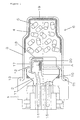
- Figure 1 shows an example of the gas generator of the present invention.
- Reference numeral 1 denotes a holder
- reference numeral 2 denotes a squib
- reference numeral 3 denotes a cup body
- reference numeral 4 denotes an automatic igniting agent layer
- reference numeral 5 denotes a gas generating agent.
- the automatic igniting agent layer is formed at the bottom and on the side of the inner surface of the cup body.
- the holder 1 and the squib 2 are prepared separately and integrated by caulking.
- the holder 1 has a dish-like taper part 11 which is for inserting and setting the plug A of the squib 2, a projection 12 for setting the plug A of the squib 2 and a projection 13 for setting the cup body 3.
- resins such as polybutylene terephthalate, polyethylene terephthalate, nylon 6, nylon 66, polyphenylene sulfide, polyphenylene oxide, polyethylene imide, polyether imide, polyether ether ketone and polyether sulfone, or one in which glass fiber or carbon is added thereto are molded by injecting into a mold which is abbreviated in the figure.
- conductive pins 14 and 15 are put integrally on the holder 1. Each of the conductive pins 14 and 15 is integrated with the resin of the holder 1 by putting them inside the mold when the resin is injected into the above mold.
- the squib 2 include two conductive pins 14 and 15 which are installed for supplying electricity to ignite ignition agent 20, and a plug A.
- a plug A for the squib used in the present invention, glass squib which seals the plug A by the glass or a fused head squib with a plug A made of resin is preferably used.
- the material of the conductive pins 14 and 15 is preferably an alloy containing nickel, iron and stainless steel.
- the material of the plug A includes, for example, polybutylene terephthalate, polyethylene terephthalate, nylon 6 and nylon 66.
- a sealing member 16 such as O-ring is disposed between the squib 2 and the plug A when holding the plug A of the squib 2 to keep away moisture between the squib 2 and the holder 1.
- the material of the sealing member 16 is not particularly limited but those difficult to permeate water such as nitrile, silicon and ethylene propylene rubber are preferable. It is preferable that the sealing member 16 is installed over the entire periphery of the jointed part of the holder and the squib.
- the cup body 3 has cylindrical shape with a bottom and has a plurality of linear notches 19 at the bottom.
- the notches 19 are cracked upon the combustion of the gas generating agent 5 stored in the cup body 3 and the gas is directly released into the seatbelt pretensioner which is not shown in the figure.
- Flange part 21 is formed extending outward to the radial direction at the open end of the cup body 3 and assembled to the holder 1 by caulking by projection 13 formed on the holder 1.
- Examples of the material of the cup body 3 include metals such as stainless steel, iron and aluminum.
- the automatic igniting agent layer is an agent layer which has a characteristic of being ignited automatically at a certain temperature, and is preferably in contact with the gas generating agent.
- the certain temperature refers to, for example, not lower than 150°C and lower than the ignition temperature of the gas generating agent, preferably 150°C to 250°C, which is lower than the brittle temperature of the cup body.
- the ignition temperature is measured by using a Krupp ignition point tester.
- the weight of the automatic igniting agent is at least 3 mg, preferably at least 4 mg and at least 5 mg is sufficient, and it is preferably not more than 100 mg, more preferably not more than 50 mg and further preferably not more than 20 mg. In practice, the weight is 3 to 10 mg in view of the stability over time of the gas generating agent, and preferably about 5 to 10 mg or 5 to less than 10 mg is sufficient in view of the flammability for the gas generating agent.
- the determination of the weight is calculated from the difference between the weight of the cup body before forming an automatic igniting agent and the weight of the cup body after forming the composition layer, or the difference between the weight of the cup body after forming the composition layer and the weight of the cup body after removing the composition layer.
- an automatic igniting agent and, where necessary, additives as exemplified below are dissolved or suspended in a solvent or a medium, followed by application on the inner surface of the cup body and drying.
- the solution or the suspension is dropped on the cup body and dried as it is, or dried after centrifugal application.
- drying may be conducted. That is, all or part of the inner surface of the cup body may be moistened by the solution or the suspension and then dried.
- the concentration of the automatic igniting agent to be dissolved or suspended in the solvent or the medium is preferably adjusted to 2 to 40% by weight. It is desired that the concentration of the solution is adjusted to preferably 5 to 30% by weight, more preferably 10 to 20% by weight.
- Examples of the automatic igniting agent for forming an automatic igniting agent layer include smokeless powder and nitrocellulose such as celluloid, and as a composition, one comprising saccharose, potassium chlorate or magnesium oxide, one in which silicone or urethane is added thereto (see Japanese Patent Application Laying Open (KOKAI) No. 7-232989), one comprising dextrin, potassium chlorate, zinc oxide or butyl rubber (see the above publication), a composition containing a hydrazine salt of 3-nitro-1,2,4,-triazole-5-one and an oxidant (National Publication of International Patent Application No. 8-508972) and a composition containing 5-aminotetrazole, potassium nitrate or molybdenum trioxide.
- smokeless powder and nitrocellulose such as celluloid
- a composition one comprising saccharose, potassium chlorate or magnesium oxide, one in which silicone or urethane is added thereto (see Japanese Patent Application Laying Open (KOKAI) No. 7-232989)
- the particle size is preferably not more than 50 ⁇ m, more preferably not more than 20 ⁇ m.
- additives such as a binder may be added within the range that has no substantial influence on the ignition property.
- the solvent or the medium for producing a solution or a suspension of the automatic igniting agent those having a moderate volatility are preferable.
- examples thereof include alcohols such as methanol, ethanol and butanol, ketones such as acetone, ethyl methyl ketone, isobutyl methyl ketone, diacetone alcohol and cyclohexanone, acetic acid esters such as methyl acetate, ethyl acetate, propyl acetate, butyl acetate, amyl acetate and isoamyl acetate, ethers such as ethyl lactate, DMF (dimethylformamide), diethyl ether, cellosolve, butyl cellosolve and dioxane.
- the solvent or the medium is used alone or in a mixture of two ore more kinds.
- the gas generating agent 5 is filled in direct contact with the inner circumference of the cup body 3 without a filter material and/or a coolant.
- the gas generating agent to be used contains a fuel component, an oxidant component and additives, and it is desired that these components have an excellent heat resistance. In addition, it is desired to control the oxygen balance to make the combustion gas clean.
- the fuel component include at least one member selected from the group consisting of 5-aminotetrazole, guanidine nitrate, nitroguanidine and pentaerythritol.
- oxidant component examples include at least one member selected from the group consisting of strontium nitrate, ammonium nitrate, potassium nitrate, ammonium perchlorate and potassium perchlorate.
- additives include metal oxides such as copper oxide, iron oxide and molybdenum trioxide, basic metal carbonates or basic metal nitrates as a combustion catalyst.
- examples of other additives that can be added to the gas generating agent include binders including polysaccharide derivatives such as methylcellulose, hydroxyethyl methylcellulose, hydroxypropyl methylcellulose, hydroxyethyl cellulose, cellulose acetate, cellulose propionate, cellulose acetate butyrate, nitrocellulose, microcrystalline cellulose, carboxymethyl cellulose, water-soluble cellulose ether, polyvinyl alcohol, guar gum and starch, organic binders such as polyacrylic amide and polyvinylpyrrolidone and inorganic binders such as molybdenum disulfide, acid clay, talc, bentonite, diatomaceous earth, kaolin, silica, alumina and synthesized hydrotalcite.
- binders including polysaccharide derivatives such as methylcellulose, hydroxyethyl methylcellulose, hydroxypropyl methylcellulose, hydroxyethyl cellulose, cellulose acetate, cellulose propionate
- a preferred gas generating agent contains 5-aminotetrazole and guanidine nitrate or nitroguanidine as fuel components, strontiumnitrate and ammoniumperchlorate as oxidant components, metal oxides such as copper oxide and iron oxide, basic metal carbonates such as basic copper carbonate, basic cobalt carbonate, basic zinc carbonate, basic iron carbonate and basic manganese carbonate, or basic nitrates such as basic copper nitrate, basic cobalt nitrate, basic zinc nitrate, basic iron nitrate and basic manganese nitrate as a combustion catalyst, and hydroxypropyl methylcellulose and polyacrylic amide as binders.
- metal oxides such as copper oxide and iron oxide
- basic metal carbonates such as basic copper carbonate, basic cobalt carbonate, basic zinc carbonate, basic iron carbonate and basic manganese carbonate
- basic nitrates such as basic copper nitrate, basic cobalt nitrate, basic zinc nitrate, basic iron
- a more preferred gas generating agent contains 0 to 30% by weight of 5-aminotetrazole and 10 to 45% by weight of guanidine nitrate or 30 to 50% by weight of nitroguanidine as fuel components, 15 to 35% by weight of strontium nitrate and 15 to 35% by weight of ammonium perchlorate as oxidant components, copper oxide as a combustion catalyst and 1 to 10% by weight of a binder.
- the gas generating agent is used in the range of preferably 50 mg to 2000 mg, more preferably 300 mg to 2000 mg.
- the gas generating agent used in the present invention may be formed into, for example, a molded article having a desired shape so as to be put in a seatbelt pretensioner.
- the shape of the molded article is not particularly limited and after adding water or an organic solvent to the gas generating agent depending on the types and amounts of (a) fuel, (b) oxidant, (c) binder and (d) combustion control agent, the solution is mixed until homogeneous and the resultant is kneaded, extrusion molded and cut into a column-shaped or cylindrical molded article or formed into pellet molded articles using a tableting machine.
- an anticaking agent is first added to the fuel component and the oxidant, and after mixing separately in V-mixers, pulverization is conducted.
- the pulverized fuel component, the pulverized oxidant, a molding auxiliary agent and a combustion control agent are weighed in pre-determined amounts and mixed in a V-mixer homogeneously. Then, the mixture is introduced to a press molding machine and subjected to a heat treatment. The obtained molded article is used as a gas generating agent.
- the fuel component and the oxidant are pulverized, the pulverized fuel component, the pulverized oxidant, a molding auxiliary agent and a combustion control agent are weighed in pre-determined amounts and mixed in a V-mixer homogeneously in the same manner.
- a viscous wet agent is prepared.
- the agent is extrusion molded to a desired shape using a vacuum kneading extruder, cut accordingly and subj ected to a heat treatment.
- the extrusion molded article obtained in this way is used as a gas generating agent composition.
- the gas generator 6 of the present invention it is preferable that at least a filter material, a transfer charge or a coolant is not used, it is more preferable that a filter material and a transfer charge, a filter material and a coolant, or a transfer charge and a coolant are not used, and it is particularly preferable that none of filter material, transfer charge or coolant is used.
- the gas generator 6 of the present invention is preferably used as a gas generator for seatbelt pretensioners or anti-submarine devices (restraint system for forward movement of automobile occupant).
- the gas generator 6 of the present invention constituted as described above can be prepared according to the following procedures. First, conductive pins 14 and 15 of the squib 2 are inserted into the holder 1 and the squib 2 is mounted so as to be inserted into the taper part 11 of the holder 1 via a sealing member 16. Then, by fitting the fitting projection 12 to cover the surface of the squib 2, squib 2 is integrally mounted on the holder 1. Next, the cup body 3 filled with the gas generating agent 5 is fitted to the holder 1 to which the squib 2 is mounted and fixed by caulking via a fitting projection 13.
- the activation of the gas generator 6 of the present invention is described in the following.
- electricity runs through the conductive pins 14 and 15 installed on the squib 2 to ignite an ignition agent 20.
- the gas generating agent 5 is ignited and burnt to discharge gas.
- the temperature and the pressure inside the squib 2 become high.
- the gas and particles with increased temperature and pressure due to further combustion are released into the squib case 17. In other words, due to combustion, the temperature and the pressure inside the squib case 17 become even higher.
- the high temperature, high pressure gas is spouted at a blast to gas generating agent 5 inside the cup body 3 through the ignition hole 18 of the squib case 17 with the burning gas generating agent. Since the squib case 17 is fixed to the holder 1 by fitting, it will not be blown to the direction of the gas generating agent 5. Then, a large amount of gas generated in the cup body 3 due to the combustion of the gas generating agent 5 rapidly increases the inner pressure of the cup body 3 and finally the notch 19 formed at the bottom of the cup body 3 is cracked, and the gas is introduced into the seatbelt pretensioner (not shown) to activate the seatbelt pretensioner.
- Example 1 Example 1
- gas generator of the present invention is explained in detail by means of Examples, but the gas generator of the present invention is not limited to the following Examples.
- Nitrocellulose was used as an automatic igniting agent. Nitrocellulose was dissolved in ethyl acetate and the solution was adjusted to a concentration of 15% by weight and directly injected into a cup body by a dispenser. By rotating the cup body at this time, the solution was applied to the entire inner surface to form a layer. Separately, one in which a layer is formed only at the bottom of a cup body was also prepared. The amount of the automatic igniting agent can be easily controlled by changing the injection amount. Next, they were put in a drier set to 60°C to volatilize the medium (solvent) so as to attach the layer to the cup body completely.
- cup bodies having an automatic igniting agent layer were filled with a gas generating agent, and gas generators having a squib and a holder formed integrally with the squib and fixedly sealing the squib in the cup body were prepared and subjected to experiments.
- a bonfire test was conducted using an apparatus as shown in Figure 2.
- the prepared gas generator 6 was set on a 3.5 cc cylinder 7 (a bonfire test jig for setting gas generator) and fixed at the position 400 mm from the tip of a propane gas burner 9 (diameter 60 mm) and heated by the burner 9. The flame height of the burner 9 at this point was adjusted to 600 mm.
- the diameter of the gas discharging hole of the 3.5 cc cylinder 7 used was 1.0 mm and nitrocellulose was used as the automatic igniting agent.
- Gas generators equipped with a cup body having an automatic igniting agent layer of 5 mg to 46 mg were used.
- gas generating agent a gas generating agent composition containing 7.2 parts by weight of 5-aminotetrazole and 29. 2 parts by weight of guanidine nitrate as the fuel components, 29.8 parts by weight of strontium nitrate and 29. 8 parts by weight of ammonium perchlorate as the oxidant components and 4.0 parts by weight of binder was used, and a sample containing 1800 mg of the gas generating agent was used. The time from firing to the catch of the sound was measured.
- the activation time of the gas generator can be shortened with at least 5 mg of the automatic igniting agent.
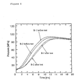
- 5% Peak indicates the time [ms] from the electricity flow to the point where the pressure increased by 5% assuming the maximum pressure to be 100%.
- tPeak indicates the time [ms] from the electricity flow to the point where the maximum pressure is reached and Pmax indicates the maximum pressure [MPa] .
- the 5% Peak time value is an index for the time from the electricity flow to the ignition of the gas generating agent.
- the sample in which the amount of the automatic igniting agent was limited has a smaller variation degree of the gas generation before and after the test than that of the sample having a large amount of automatic igniting agent. Accordingly, it is understood that the automatic igniting agent has a smaller impact on the gas generating agent.
- the gas generating agent used in the test is the same as the gas generating agent used in the above bonfire test (composition and amount of each component).
- the gas generator using 20 mg of automatic igniting agent is advantageous in that the automatic activation time of the gas generating agent at high temperatures can be shortened.
- the gas generator using 8 mg of the automatic igniting agent is superior in not only that point but also the stability over time. Accordingly, by limiting the amount of use of the automatic igniting agent, long term stability of the product is ensured when installed on an automobile.
- the automatic activation time of the gas generator at high temperatures can be shortened even with an extremely small amount of the automatic igniting agent of a mg level.
- a micro gas generator with an automatic ignition function activated before embrittlement by heat without loss of the cleanliness of exhaust gas can be obtained.
- an automatic ignition micro gas generator having superior stability over time can be obtained.
Landscapes
- Engineering & Computer Science (AREA)
- Physics & Mathematics (AREA)
- Fluid Mechanics (AREA)
- Mechanical Engineering (AREA)
- General Engineering & Computer Science (AREA)
- Air Bags (AREA)
- Feeding, Discharge, Calcimining, Fusing, And Gas-Generation Devices (AREA)
- Automotive Seat Belt Assembly (AREA)
Abstract
Description
| No | Automatic igniting agent | Part applied | Amount of automatic igniting | Activation time | |
| 1 | none | - | 3 min 54 | ||
| 2 | none | - | 3 min 58 sec | ||
| 3 | nitrocellulose applied | entire inner surface | 5.1 | 2 min 55 | |
| 4 | nitrocellulose applied | only the bottom | 5.7 mg | 3 | |
| 5 | nitrocellulose applied | entire inner surface | 14.9 | 2 min 54 | |
| 6 | nitrocellulose applied | only the bottom | 13.0 | 2 min 59 | |
| 7 | nitrocellulose applied | entire inner surface | 46.0 | 2 min 44 | |
| 8 | nitrocellulose applied | only the bottom | 30.4 | 2 min 52 sec |
| Results of accelerated test for stability over time (8 mg automatic igniting agent applied) | |||
| 5% Peak | tPeak | Pmax | |
| A-1 before test | 1.24 | 14.86 | 90.06 |
| A-1 after test | 1.22 | 15.18 | 90.26 |
| A-2 before test | 1.12 | 15.76 | 90.8 |
| A-2 after test | 1.76 | 15.4 | 90.82 |
| Results of accelerated test for stability over time (20 mg automatic igniting agent applied) | |||
| 5% Peak | tPeak | Pmax | |
| B-1 before test | 1.16 | 13.12 | 93.6 |
| B-1 after test | 1.36 | 16.88 | 88.35 |
| B-2 before test | 0.94 | 13.5 | 91.3 |
| B-2 after test | 1.56 | 16.48 | 88.73 |
Claims (10)
- A gas generator comprising a gas generating agent, a cup body for filling the gas generating agent therein, and a holder with a squib, fixedly sealing the squib in the cup body,
wherein an automatic igniting agent layer is provided on the inner surface of the cup body. - The gas generator according to claim 1, wherein the weight of the automatic igniting agent layer is at least 3 mg.
- The gas generator according to claim 1 or 2, wherein the automatic igniting agent layer is formed by applying a solution containing an automatic igniting agent on the inner surface of the cup body and then drying.
- The gas generator according to any one of claims 1 to 3, wherein the automatic igniting agent layer is provided on the inner surface of a combustion chamber for the gas generating agent and wherein the weight of the automatic igniting agent layer is at least 4 mg.
- The gas generator according to any one of claims 1 to 4,
wherein the automatic igniting agent layer is in contact with the gas generating agent. - The gas generator according to any one of claims 1 to 5, wherein the ignition temperature of the automatic igniting agent is not lower than 150°C and lower than the ignition temperature of the gas generating agent.
- The gas generator according to any one of claims 1 to 5, wherein the ignition temperature of the automatic igniting agent is 150 to 250°C.
- The gas generator according to any one of claims 1 to 7, wherein the weight of the automatic igniting agent layer is 3 mg to less than 10 mg.
- The gas generator according to any one of claims 1 to 8, wherein a filter material, a transfer charge or a coolant is not used.
- The gas generator according to any one of claims 1 to 9, wherein the gas generating agent is used in the range of 50 mg to 2000 mg.
Applications Claiming Priority (3)
| Application Number | Priority Date | Filing Date | Title |
|---|---|---|---|
| JP2002252835 | 2002-08-30 | ||
| JP2002252835 | 2002-08-30 | ||
| PCT/JP2003/011089 WO2004025210A1 (en) | 2002-08-30 | 2003-08-29 | Micro gas generator with automatic ignition function |
Publications (4)
| Publication Number | Publication Date |
|---|---|
| EP1541958A1 true EP1541958A1 (en) | 2005-06-15 |
| EP1541958A4 EP1541958A4 (en) | 2006-12-20 |
| EP1541958B1 EP1541958B1 (en) | 2012-03-07 |
| EP1541958B2 EP1541958B2 (en) | 2018-09-19 |
Family
ID=31986276
Family Applications (1)
| Application Number | Title | Priority Date | Filing Date |
|---|---|---|---|
| EP03795265.2A Expired - Lifetime EP1541958B2 (en) | 2002-08-30 | 2003-08-29 | Micro gas generator with automatic ignition function |
Country Status (7)
| Country | Link |
|---|---|
| US (1) | US7377545B2 (en) |
| EP (1) | EP1541958B2 (en) |
| JP (2) | JP4668617B2 (en) |
| CN (1) | CN100494867C (en) |
| AT (1) | ATE548627T1 (en) |
| AU (1) | AU2003264358A1 (en) |
| WO (1) | WO2004025210A1 (en) |
Cited By (6)
| Publication number | Priority date | Publication date | Assignee | Title |
|---|---|---|---|---|
| EP1803698A3 (en) * | 2005-12-28 | 2009-08-12 | Showa Kinzoku Kogyo Co., Ltd. | Ignition charge for initiator, method for production thereof and method for production of initiator using the ignition charge |
| US8176851B2 (en) | 2006-01-18 | 2012-05-15 | Nippon Kayaku Kabushiki Kaisha | Small gas generator for gas actuator and pretensioner system |
| EP2489649A4 (en) * | 2009-10-15 | 2014-01-01 | Nippon Kayaku Kk | Gas generating agent composition, molded product of the composition, and gas generation device equipped with the molded product |
| DE102014016923B3 (en) * | 2014-11-17 | 2016-02-25 | Elisabeth Dürschinger | Primer for occupant restraint systems |
| WO2016078634A1 (en) | 2014-11-17 | 2016-05-26 | Günter Dürschinger | Ignition capsule for occupant restraint systems |
| DE102015014124A1 (en) | 2015-11-03 | 2017-05-04 | Ems-Patvag s.r.o. | Primer for occupant restraint systems |
Families Citing this family (20)
| Publication number | Priority date | Publication date | Assignee | Title |
|---|---|---|---|---|
| EP1568673B1 (en) * | 2002-11-22 | 2013-09-25 | Nippon Kayaku Kabushiki Kaisha | Gas generating agent, process for production thereof, and gas generators for air bags |
| US8496266B2 (en) * | 2005-06-02 | 2013-07-30 | Tk Holdings, Inc. | Gas generating system |
| JP4907931B2 (en) * | 2005-09-15 | 2012-04-04 | 日本化薬株式会社 | Gas generator |
| US7942990B2 (en) * | 2006-12-18 | 2011-05-17 | Daicel Chemical Industries, Ltd. | Hybrid inflator |
| CN100584207C (en) * | 2007-06-18 | 2010-01-27 | 周华 | Agastache mate tea |
| CN103465861A (en) * | 2008-09-30 | 2013-12-25 | Trw空气气袋系统股份有限公司 | Gas generator, method for the production thereof and module having the gas generator |
| JP5545831B2 (en) * | 2010-04-08 | 2014-07-09 | 日本化薬株式会社 | Gas generator |
| JP5815543B2 (en) * | 2010-10-06 | 2015-11-17 | 日本化薬株式会社 | GAS GENERATOR, GAS GENERATOR HOLDER, AND METHOD FOR PRODUCING GAS GENERATOR HOLDER |
| DE102011012773B4 (en) | 2011-03-01 | 2024-03-07 | Zf Airbag Germany Gmbh | Gas generator with early ignition agent |
| US20120234193A1 (en) | 2011-03-17 | 2012-09-20 | Special Devices, Inc. | Igniter with a locked consolidated powder charge |
| JP5795237B2 (en) * | 2011-10-24 | 2015-10-14 | 株式会社ダイセル | Gas generator for personnel restraint system |
| DE102012016431A1 (en) * | 2012-08-21 | 2014-02-27 | Trw Airbag Systems Gmbh | Pyrotechnic igniter useful in safety devices, preferably belt tensioner, engine bonnet stand for vehicles, comprises ignition bridge, pyrotechnic composition, which is associated with ignition bridge, and energy absorbing additive |
| WO2014147721A1 (en) * | 2013-03-18 | 2014-09-25 | 株式会社日立システムズ | Igniter, igniter assembly, and detection system and detection method therefor |
| US9676366B2 (en) | 2014-02-20 | 2017-06-13 | Tk Holdings Inc. | Autoigniting, antivirbration airbag inflator pad |
| US9440615B2 (en) * | 2014-12-10 | 2016-09-13 | Autoliv Asp, Inc. | Initiator assemblies |
| CN105061123A (en) * | 2015-08-17 | 2015-11-18 | 陕西庆华汽车安全系统有限公司 | Gas production drug for automobile safety belt pretensioner and preparation method of gas production drug |
| US10677576B1 (en) * | 2015-12-30 | 2020-06-09 | Systima Technologies, Inc. | Multistage thermal trigger |
| CN109311446B (en) | 2016-03-31 | 2021-10-22 | B/E航空公司 | System and method for protecting occupants in reclining-mounted aircraft seats |
| JP6880505B2 (en) * | 2017-07-14 | 2021-06-02 | 株式会社ダイセル | Discharger and gas generator |
| CN113390307B (en) * | 2021-05-27 | 2024-11-26 | 张清云 | A miniature and lightweight electrode plug |
Family Cites Families (13)
| Publication number | Priority date | Publication date | Assignee | Title |
|---|---|---|---|---|
| US5290060A (en) * | 1992-12-14 | 1994-03-01 | Morton International, Inc. | Hybrid gas generator for air bag inflatable restraint systems |
| JPH05185899A (en) † | 1992-01-10 | 1993-07-27 | Takata Kk | Inflator of air bag device |
| US5648634A (en) † | 1993-10-20 | 1997-07-15 | Quantic Industries, Inc. | Electrical initiator |
| JPH07232989A (en) | 1993-12-27 | 1995-09-05 | Nippon Kayaku Co Ltd | Automatically ignitable explosive composition |
| JPH07232613A (en) | 1993-12-28 | 1995-09-05 | Nippon Kayaku Co Ltd | Airbag gas generators and squibs |
| US5380380A (en) | 1994-02-09 | 1995-01-10 | Automotive Systems Laboratory, Inc. | Ignition compositions for inflator gas generators |
| JP3678827B2 (en) | 1995-12-20 | 2005-08-03 | 日本化薬株式会社 | Pin type squib for gas generator |
| FR2754050B1 (en) † | 1996-10-01 | 1998-10-30 | Livbag Snc | PYROTECHNIC GAS MICROGENERATOR WITH BLOCKED TWO-WIRE SOCKET |
| US5834679A (en) † | 1996-10-30 | 1998-11-10 | Breed Automotive Technology, Inc. | Methods of providing autoignition for an airbag inflator |
| JPH10325699A (en) * | 1997-05-23 | 1998-12-08 | Nichiyu Giken Kogyo Kk | Igniter |
| US6136114A (en) | 1997-09-30 | 2000-10-24 | Teledyne Industries, Inc. | Gas generant compositions methods of production of the same and devices made therefrom |
| JP4131486B2 (en) | 1999-07-09 | 2008-08-13 | 日本化薬株式会社 | Auto-igniting enhancer composition |
| JP2004535966A (en) † | 2000-11-28 | 2004-12-02 | オートモーティブ システムズ ラボラトリー インコーポレーテッド | Gas generator and assembly method |
-
2003
- 2003-08-29 AU AU2003264358A patent/AU2003264358A1/en not_active Abandoned
- 2003-08-29 WO PCT/JP2003/011089 patent/WO2004025210A1/en not_active Ceased
- 2003-08-29 CN CNB038204118A patent/CN100494867C/en not_active Expired - Fee Related
- 2003-08-29 JP JP2004535892A patent/JP4668617B2/en not_active Expired - Lifetime
- 2003-08-29 EP EP03795265.2A patent/EP1541958B2/en not_active Expired - Lifetime
- 2003-08-29 US US10/524,751 patent/US7377545B2/en not_active Expired - Lifetime
- 2003-08-29 AT AT03795265T patent/ATE548627T1/en active
-
2010
- 2010-10-20 JP JP2010235461A patent/JP2011088141A/en not_active Withdrawn
Cited By (8)
| Publication number | Priority date | Publication date | Assignee | Title |
|---|---|---|---|---|
| EP1803698A3 (en) * | 2005-12-28 | 2009-08-12 | Showa Kinzoku Kogyo Co., Ltd. | Ignition charge for initiator, method for production thereof and method for production of initiator using the ignition charge |
| US7685939B2 (en) | 2005-12-28 | 2010-03-30 | Showa Kinzoku Kogyo Co., Ltd | Ignition charge for initiator and method of production |
| US8176851B2 (en) | 2006-01-18 | 2012-05-15 | Nippon Kayaku Kabushiki Kaisha | Small gas generator for gas actuator and pretensioner system |
| EP2489649A4 (en) * | 2009-10-15 | 2014-01-01 | Nippon Kayaku Kk | Gas generating agent composition, molded product of the composition, and gas generation device equipped with the molded product |
| DE102014016923B3 (en) * | 2014-11-17 | 2016-02-25 | Elisabeth Dürschinger | Primer for occupant restraint systems |
| WO2016078634A1 (en) | 2014-11-17 | 2016-05-26 | Günter Dürschinger | Ignition capsule for occupant restraint systems |
| US10209041B2 (en) | 2014-11-17 | 2019-02-19 | Ems-Patvag s.r.o. | Detonator for passenger restraint systems |
| DE102015014124A1 (en) | 2015-11-03 | 2017-05-04 | Ems-Patvag s.r.o. | Primer for occupant restraint systems |
Also Published As
| Publication number | Publication date |
|---|---|
| JPWO2004025210A1 (en) | 2006-01-12 |
| WO2004025210A1 (en) | 2004-03-25 |
| US20060162607A1 (en) | 2006-07-27 |
| CN1678879A (en) | 2005-10-05 |
| JP2011088141A (en) | 2011-05-06 |
| EP1541958B1 (en) | 2012-03-07 |
| JP4668617B2 (en) | 2011-04-13 |
| ATE548627T1 (en) | 2012-03-15 |
| EP1541958A4 (en) | 2006-12-20 |
| AU2003264358A1 (en) | 2004-04-30 |
| EP1541958B2 (en) | 2018-09-19 |
| US7377545B2 (en) | 2008-05-27 |
| CN100494867C (en) | 2009-06-03 |
Similar Documents
| Publication | Publication Date | Title |
|---|---|---|
| US7377545B2 (en) | Micro gas generator with automatic ignition function | |
| JP3992924B2 (en) | Ignition enhancer composition for airbag inflator | |
| EP2910536B1 (en) | Gas-generating-agent composition and gas generator using same | |
| EP2426016A1 (en) | Gas generator | |
| JPWO2007083663A1 (en) | Compact gas generator and pretensioner system for gas actuator | |
| JP2000511866A (en) | Ignition type gas generation method that generates non-toxic, odorless and colorless gas without generating fine particles | |
| CN1195620A (en) | Gas generating pellets, gas generator and air bag device | |
| US6368432B2 (en) | Gas generating compositions | |
| JP2005313812A (en) | Gas producer | |
| JP5689065B2 (en) | GAS GENERATOR COMPOSITION, MOLDED BODY THEREOF, AND GAS GENERATOR USING THE SAME | |
| CN1356944A (en) | Multi-stage expansion type hybrid inflator | |
| CN1420825A (en) | Hybrid inflator | |
| JP4490920B2 (en) | Gas generator mounting structure and airbag module | |
| KR100257145B1 (en) | An all pyrotechnic method of generating a particulate-free, non-toxic odorless and colorless gas | |
| JP4514024B2 (en) | Gunpowder molded body and gas generator having the same | |
| EP1264813B1 (en) | Gas generator with automatic firing function | |
| US20090140510A1 (en) | Porous igniter coating for use in automotive airbag inflators | |
| KR20010079624A (en) | Metal oxide containing gas generating composition | |
| JP3910897B2 (en) | Inflator | |
| JP4994787B2 (en) | Gas generator | |
| WO2005123631A1 (en) | Firing agent for gas generating device | |
| JPH10139579A (en) | Gas generating composition and inflator structure using the same | |
| JP2012106882A (en) | Enhancer agent composition and gas generator using the same |
Legal Events
| Date | Code | Title | Description |
|---|---|---|---|
| PUAI | Public reference made under article 153(3) epc to a published international application that has entered the european phase |
Free format text: ORIGINAL CODE: 0009012 |
|
| 17P | Request for examination filed |
Effective date: 20050323 |
|
| AK | Designated contracting states |
Kind code of ref document: A1 Designated state(s): AT BE BG CH CY CZ DE DK EE ES FI FR GB GR HU IE IT LI LU MC NL PT RO SE SI SK TR |
|
| AX | Request for extension of the european patent |
Extension state: AL LT LV MK |
|
| DAX | Request for extension of the european patent (deleted) | ||
| A4 | Supplementary search report drawn up and despatched |
Effective date: 20061117 |
|
| RIC1 | Information provided on ipc code assigned before grant |
Ipc: F23Q 13/00 20060101ALI20040329BHEP Ipc: B01J 7/00 20060101ALI20040329BHEP Ipc: B60R 22/46 20060101ALI20040329BHEP Ipc: F42B 3/04 20060101AFI20061113BHEP Ipc: B60R 21/26 20060101ALI20040329BHEP |
|
| 17Q | First examination report despatched |
Effective date: 20080320 |
|
| GRAP | Despatch of communication of intention to grant a patent |
Free format text: ORIGINAL CODE: EPIDOSNIGR1 |
|
| GRAS | Grant fee paid |
Free format text: ORIGINAL CODE: EPIDOSNIGR3 |
|
| GRAA | (expected) grant |
Free format text: ORIGINAL CODE: 0009210 |
|
| AK | Designated contracting states |
Kind code of ref document: B1 Designated state(s): AT BE BG CH CY CZ DE DK EE ES FI FR GB GR HU IE IT LI LU MC NL PT RO SE SI SK TR |
|
| REG | Reference to a national code |
Ref country code: GB Ref legal event code: FG4D |
|
| REG | Reference to a national code |
Ref country code: AT Ref legal event code: REF Ref document number: 548627 Country of ref document: AT Kind code of ref document: T Effective date: 20120315 Ref country code: CH Ref legal event code: EP |
|
| REG | Reference to a national code |
Ref country code: IE Ref legal event code: FG4D |
|
| REG | Reference to a national code |
Ref country code: DE Ref legal event code: R096 Ref document number: 60340226 Country of ref document: DE Effective date: 20120503 |
|
| REG | Reference to a national code |
Ref country code: NL Ref legal event code: VDEP Effective date: 20120307 |
|
| PG25 | Lapsed in a contracting state [announced via postgrant information from national office to epo] |
Ref country code: NL Free format text: LAPSE BECAUSE OF FAILURE TO SUBMIT A TRANSLATION OF THE DESCRIPTION OR TO PAY THE FEE WITHIN THE PRESCRIBED TIME-LIMIT Effective date: 20120307 |
|
| PG25 | Lapsed in a contracting state [announced via postgrant information from national office to epo] |
Ref country code: FI Free format text: LAPSE BECAUSE OF FAILURE TO SUBMIT A TRANSLATION OF THE DESCRIPTION OR TO PAY THE FEE WITHIN THE PRESCRIBED TIME-LIMIT Effective date: 20120307 Ref country code: GR Free format text: LAPSE BECAUSE OF FAILURE TO SUBMIT A TRANSLATION OF THE DESCRIPTION OR TO PAY THE FEE WITHIN THE PRESCRIBED TIME-LIMIT Effective date: 20120608 |
|
| REG | Reference to a national code |
Ref country code: AT Ref legal event code: MK05 Ref document number: 548627 Country of ref document: AT Kind code of ref document: T Effective date: 20120307 |
|
| PG25 | Lapsed in a contracting state [announced via postgrant information from national office to epo] |
Ref country code: CY Free format text: LAPSE BECAUSE OF FAILURE TO SUBMIT A TRANSLATION OF THE DESCRIPTION OR TO PAY THE FEE WITHIN THE PRESCRIBED TIME-LIMIT Effective date: 20120307 |
|
| PG25 | Lapsed in a contracting state [announced via postgrant information from national office to epo] |
Ref country code: BE Free format text: LAPSE BECAUSE OF FAILURE TO SUBMIT A TRANSLATION OF THE DESCRIPTION OR TO PAY THE FEE WITHIN THE PRESCRIBED TIME-LIMIT Effective date: 20120307 Ref country code: RO Free format text: LAPSE BECAUSE OF FAILURE TO SUBMIT A TRANSLATION OF THE DESCRIPTION OR TO PAY THE FEE WITHIN THE PRESCRIBED TIME-LIMIT Effective date: 20120307 Ref country code: EE Free format text: LAPSE BECAUSE OF FAILURE TO SUBMIT A TRANSLATION OF THE DESCRIPTION OR TO PAY THE FEE WITHIN THE PRESCRIBED TIME-LIMIT Effective date: 20120307 Ref country code: SE Free format text: LAPSE BECAUSE OF FAILURE TO SUBMIT A TRANSLATION OF THE DESCRIPTION OR TO PAY THE FEE WITHIN THE PRESCRIBED TIME-LIMIT Effective date: 20120307 Ref country code: SI Free format text: LAPSE BECAUSE OF FAILURE TO SUBMIT A TRANSLATION OF THE DESCRIPTION OR TO PAY THE FEE WITHIN THE PRESCRIBED TIME-LIMIT Effective date: 20120307 |
|
| PG25 | Lapsed in a contracting state [announced via postgrant information from national office to epo] |
Ref country code: SK Free format text: LAPSE BECAUSE OF FAILURE TO SUBMIT A TRANSLATION OF THE DESCRIPTION OR TO PAY THE FEE WITHIN THE PRESCRIBED TIME-LIMIT Effective date: 20120307 Ref country code: PT Free format text: LAPSE BECAUSE OF FAILURE TO SUBMIT A TRANSLATION OF THE DESCRIPTION OR TO PAY THE FEE WITHIN THE PRESCRIBED TIME-LIMIT Effective date: 20120709 |
|
| PLBI | Opposition filed |
Free format text: ORIGINAL CODE: 0009260 |
|
| PLAX | Notice of opposition and request to file observation + time limit sent |
Free format text: ORIGINAL CODE: EPIDOSNOBS2 |
|
| 26 | Opposition filed |
Opponent name: TRW AIRBAG SYSTEMS GMBH Effective date: 20121207 |
|
| PG25 | Lapsed in a contracting state [announced via postgrant information from national office to epo] |
Ref country code: DK Free format text: LAPSE BECAUSE OF FAILURE TO SUBMIT A TRANSLATION OF THE DESCRIPTION OR TO PAY THE FEE WITHIN THE PRESCRIBED TIME-LIMIT Effective date: 20120307 Ref country code: AT Free format text: LAPSE BECAUSE OF FAILURE TO SUBMIT A TRANSLATION OF THE DESCRIPTION OR TO PAY THE FEE WITHIN THE PRESCRIBED TIME-LIMIT Effective date: 20120307 |
|
| PG25 | Lapsed in a contracting state [announced via postgrant information from national office to epo] |
Ref country code: IT Free format text: LAPSE BECAUSE OF FAILURE TO SUBMIT A TRANSLATION OF THE DESCRIPTION OR TO PAY THE FEE WITHIN THE PRESCRIBED TIME-LIMIT Effective date: 20120307 |
|
| REG | Reference to a national code |
Ref country code: DE Ref legal event code: R026 Ref document number: 60340226 Country of ref document: DE Effective date: 20121207 |
|
| REG | Reference to a national code |
Ref country code: CH Ref legal event code: PL |
|
| PG25 | Lapsed in a contracting state [announced via postgrant information from national office to epo] |
Ref country code: MC Free format text: LAPSE BECAUSE OF NON-PAYMENT OF DUE FEES Effective date: 20120831 |
|
| GBPC | Gb: european patent ceased through non-payment of renewal fee |
Effective date: 20120829 |
|
| PG25 | Lapsed in a contracting state [announced via postgrant information from national office to epo] |
Ref country code: LI Free format text: LAPSE BECAUSE OF NON-PAYMENT OF DUE FEES Effective date: 20120831 Ref country code: CH Free format text: LAPSE BECAUSE OF NON-PAYMENT OF DUE FEES Effective date: 20120831 Ref country code: ES Free format text: LAPSE BECAUSE OF FAILURE TO SUBMIT A TRANSLATION OF THE DESCRIPTION OR TO PAY THE FEE WITHIN THE PRESCRIBED TIME-LIMIT Effective date: 20120618 |
|
| PLAF | Information modified related to communication of a notice of opposition and request to file observations + time limit |
Free format text: ORIGINAL CODE: EPIDOSCOBS2 |
|
| REG | Reference to a national code |
Ref country code: IE Ref legal event code: MM4A |
|
| PLBB | Reply of patent proprietor to notice(s) of opposition received |
Free format text: ORIGINAL CODE: EPIDOSNOBS3 |
|
| PG25 | Lapsed in a contracting state [announced via postgrant information from national office to epo] |
Ref country code: IE Free format text: LAPSE BECAUSE OF NON-PAYMENT OF DUE FEES Effective date: 20120829 Ref country code: BG Free format text: LAPSE BECAUSE OF FAILURE TO SUBMIT A TRANSLATION OF THE DESCRIPTION OR TO PAY THE FEE WITHIN THE PRESCRIBED TIME-LIMIT Effective date: 20120607 Ref country code: GB Free format text: LAPSE BECAUSE OF NON-PAYMENT OF DUE FEES Effective date: 20120829 |
|
| PG25 | Lapsed in a contracting state [announced via postgrant information from national office to epo] |
Ref country code: CZ Free format text: LAPSE BECAUSE OF NON-PAYMENT OF DUE FEES Effective date: 20130829 Ref country code: TR Free format text: LAPSE BECAUSE OF FAILURE TO SUBMIT A TRANSLATION OF THE DESCRIPTION OR TO PAY THE FEE WITHIN THE PRESCRIBED TIME-LIMIT Effective date: 20120307 |
|
| PG25 | Lapsed in a contracting state [announced via postgrant information from national office to epo] |
Ref country code: LU Free format text: LAPSE BECAUSE OF NON-PAYMENT OF DUE FEES Effective date: 20120829 |
|
| PG25 | Lapsed in a contracting state [announced via postgrant information from national office to epo] |
Ref country code: HU Free format text: LAPSE BECAUSE OF FAILURE TO SUBMIT A TRANSLATION OF THE DESCRIPTION OR TO PAY THE FEE WITHIN THE PRESCRIBED TIME-LIMIT Effective date: 20030829 |
|
| PLCK | Communication despatched that opposition was rejected |
Free format text: ORIGINAL CODE: EPIDOSNREJ1 |
|
| APBM | Appeal reference recorded |
Free format text: ORIGINAL CODE: EPIDOSNREFNO |
|
| APBP | Date of receipt of notice of appeal recorded |
Free format text: ORIGINAL CODE: EPIDOSNNOA2O |
|
| APAH | Appeal reference modified |
Free format text: ORIGINAL CODE: EPIDOSCREFNO |
|
| APBQ | Date of receipt of statement of grounds of appeal recorded |
Free format text: ORIGINAL CODE: EPIDOSNNOA3O |
|
| REG | Reference to a national code |
Ref country code: FR Ref legal event code: PLFP Year of fee payment: 14 |
|
| REG | Reference to a national code |
Ref country code: FR Ref legal event code: PLFP Year of fee payment: 15 |
|
| APBU | Appeal procedure closed |
Free format text: ORIGINAL CODE: EPIDOSNNOA9O |
|
| REG | Reference to a national code |
Ref country code: FR Ref legal event code: PLFP Year of fee payment: 16 |
|
| PUAH | Patent maintained in amended form |
Free format text: ORIGINAL CODE: 0009272 |
|
| STAA | Information on the status of an ep patent application or granted ep patent |
Free format text: STATUS: PATENT MAINTAINED AS AMENDED |
|
| 27A | Patent maintained in amended form |
Effective date: 20180919 |
|
| AK | Designated contracting states |
Kind code of ref document: B2 Designated state(s): AT BE BG CH CY CZ DE DK EE ES FI FR GB GR HU IE IT LI LU MC NL PT RO SE SI SK TR |
|
| REG | Reference to a national code |
Ref country code: DE Ref legal event code: R102 Ref document number: 60340226 Country of ref document: DE |
|
| PGFP | Annual fee paid to national office [announced via postgrant information from national office to epo] |
Ref country code: IT Payment date: 20180919 Year of fee payment: 16 |
|
| PG25 | Lapsed in a contracting state [announced via postgrant information from national office to epo] |
Ref country code: FR Free format text: LAPSE BECAUSE OF NON-PAYMENT OF DUE FEES Effective date: 20190831 |
|
| PGFP | Annual fee paid to national office [announced via postgrant information from national office to epo] |
Ref country code: DE Payment date: 20220712 Year of fee payment: 20 |
|
| REG | Reference to a national code |
Ref country code: DE Ref legal event code: R071 Ref document number: 60340226 Country of ref document: DE |