EP1541899A1 - Locking device for locking a turnable means - Google Patents
Locking device for locking a turnable means Download PDFInfo
- Publication number
- EP1541899A1 EP1541899A1 EP04105435A EP04105435A EP1541899A1 EP 1541899 A1 EP1541899 A1 EP 1541899A1 EP 04105435 A EP04105435 A EP 04105435A EP 04105435 A EP04105435 A EP 04105435A EP 1541899 A1 EP1541899 A1 EP 1541899A1
- Authority
- EP
- European Patent Office
- Prior art keywords
- locking
- locking device
- locking element
- aperture
- gearbox
- Prior art date
- Legal status (The legal status is an assumption and is not a legal conclusion. Google has not performed a legal analysis and makes no representation as to the accuracy of the status listed.)
- Granted
Links
Images


Classifications
-
- F—MECHANICAL ENGINEERING; LIGHTING; HEATING; WEAPONS; BLASTING
- F16—ENGINEERING ELEMENTS AND UNITS; GENERAL MEASURES FOR PRODUCING AND MAINTAINING EFFECTIVE FUNCTIONING OF MACHINES OR INSTALLATIONS; THERMAL INSULATION IN GENERAL
- F16H—GEARING
- F16H57/00—General details of gearing
- F16H57/02—Gearboxes; Mounting gearing therein
- F16H57/021—Shaft support structures, e.g. partition walls, bearing eyes, casing walls or covers with bearings
-
- F—MECHANICAL ENGINEERING; LIGHTING; HEATING; WEAPONS; BLASTING
- F16—ENGINEERING ELEMENTS AND UNITS; GENERAL MEASURES FOR PRODUCING AND MAINTAINING EFFECTIVE FUNCTIONING OF MACHINES OR INSTALLATIONS; THERMAL INSULATION IN GENERAL
- F16C—SHAFTS; FLEXIBLE SHAFTS; ELEMENTS OR CRANKSHAFT MECHANISMS; ROTARY BODIES OTHER THAN GEARING ELEMENTS; BEARINGS
- F16C11/00—Pivots; Pivotal connections
- F16C11/04—Pivotal connections
- F16C11/10—Arrangements for locking
-
- F—MECHANICAL ENGINEERING; LIGHTING; HEATING; WEAPONS; BLASTING
- F16—ENGINEERING ELEMENTS AND UNITS; GENERAL MEASURES FOR PRODUCING AND MAINTAINING EFFECTIVE FUNCTIONING OF MACHINES OR INSTALLATIONS; THERMAL INSULATION IN GENERAL
- F16H—GEARING
- F16H57/00—General details of gearing
- F16H57/02—Gearboxes; Mounting gearing therein
- F16H57/021—Shaft support structures, e.g. partition walls, bearing eyes, casing walls or covers with bearings
- F16H57/022—Adjustment of gear shafts or bearings
- F16H2057/0221—Axial adjustment
Definitions
- the present invention relates to a locking device for locking a turnable means according to the preamble of claim 1.
- gearbox in a vehicle needs to be maintained with unchanged quality despite varying operating conditions. It is therefore necessary that it be possible for the changes in length which gearbox shafts undergo due to varying temperatures to be absorbed without affecting gearbox function. Many gearboxes therefore have axial play in the bearings of their mainshaft and countershaft so that such shaft length changes can be absorbed.
- Such axial play may be catered for by at least one out of the respective mainshaft and countershaft bearings being provided with an axially movable bearing race.
- the respective mainshaft and countershaft bearings are usually applied in apertures in an endwall of the gearbox.
- the respective movable bearing races are during operation enabled to reposition themselves in said apertures by axial play defined by the position of a so-called ring screw applied from the outside of the gearbox.
- the ring screw comprises an external gripping portion for turning the ring screw and a tubular portion with external threads intended to be screwed into correspondingly shaped internal threads in the aperture.
- a locking device is usually used for locking the ring screw in the rotational position which results in the desired amount of play.
- a conventional such locking device comprises a washer fastened by means of a bolt in one of two holes provided adjacent to the aperture in the endwall.
- the gripping portion of each ring screw comprises a multiplicity of recesses evenly distributed along a peripheral surface.
- the washer fits positively by shape into one of the recesses and locks the ring screw.
- the bolt is applied in one of the two holes whereby the washer can be inserted in a recess with the least possible adjustment of the rotational position of the ring screw.
- the ring screw can thus be locked in a relatively large number of fixed rotational positions per revolution.
- the axial play desired for the movable bearing race can thus be provided with good accuracy.
- the gearbox endwall is relatively sensitive from the strength point of view, at least in the vicinity of the aperture for the countershaft. It would therefore be desirable not to have to drill two holes and mill planar surfaces round the holes in this area, operations which are necessary for fastening the known locking device.
- One object of the present invention is to provide a locking device which can in a functional manner lock in a large number of fixed rotational positions a turnable means which comprises peripheral recesses, while at the same time the locking device can be fastened with reduced machining of the area adjacent to the turning means.
- the locking device thus comprises a locking element with a locking surface so shaped that it can be inserted in any desired recess of the turnable means.
- a locking surface makes it possible to lock the turnable means in one rotational position per recess per revolution.
- the locking surface of the locking element is thus also so shaped as to enable it to accommodate the protruding portions inevitably present between adjacent recesses.
- Such an accommodating locking surface also makes it possible to lock the turnable means in one further rotational position per protruding portion per revolution.
- the locking element can thus lock the turnable means in two rotational positions per recess per revolution.
- Such a locking element thus provides a locking capacity corresponding to that of a conventional locking device which has a washer applicable in one of two possible holes by the means of a bolt.
- the locking element according to the present invention need only be applicable in one position.
- Said fastener can thus provide for application of the locking element by means of, for example, only one hole.
- a suitably shaped locking element enables this hole to be situated at a distance from the sensitive area which is immediately adjacent to the turnable means.
- said locking surface comprises two convex areas and an intermediate concave area.
- the convex areas may be so shaped that they each fill the side region of the recess when they are in an inserted state.
- the locking surface can thus be inserted in each of said recesses in order to lock the turnable means.
- the presence of the concave area between the convex areas does not reduce the ability of the locking element to lock the turnable means when locking engagement between the locking surface and the recess is substantially effected at the side regions of the recess.
- the concave area has with advantage a concave shape which continues the shape of the protruding portions of the turnable means.
- the concave area can thus accommodate and grip any desired protruding portion situated between two recesses so that the turnable means is locked in a rotational position defined by the position of the protruding portion.
- the locking element has running through it a hole whereby a fastener in the form of a fastening means is adapted to being applied through said hole in order to fasten the locking element to a surface.
- a fastening means in the form of a bolt only one threaded hole need be applied in said surface for accommodating the fastening means and the fastened locking element.
- the locking element may comprise a base portion provided with said hole for accommodating the fastening means, and a locking portion which protrudes from the base portion and has a peripheral surface which comprises said locking surface.
- a locking portion of suitable extent makes it possible for the hole for accommodating the fastening means to be applied at a distance from the turnable means.
- said fastener comprises a stop surface against which an abutting surface of the locking element is adapted to being applied to prevent rotary movement of the locking element about the fastening means.
- the locking element may comprise an abutting portion which protrudes from the base portion and has a peripheral surface which comprises said abutting surface. The length of the abutting portion and its extent in a direction away from the base portion are such that the abutting surface comes into contact with a suitable stationary stop surface.
- said stop surface is a suitably situated surface adjacent to the turnable means.
- the turnable means is an annular screw means which can be screwed into an aperture with delineating surfaces which are provided with threads whereby the locking element is adapted to locking the screw means in a rotational position which corresponds to a desired axially inserted position of the screw means in the aperture.
- a screw means in a fitted state, is limited to following a helical path, it is possible to lock a screw means in a desired axial position by locking the screw means in a corresponding rotational position.
- Said aperture may be accommodated in an endwall of a gearbox and the annular screw means may be adapted to adjusting axial play for a movable bearing race of a bearing which supports a rotatable shaft in the gearbox.
- Axial play as desired for the movable bearing race can be provided by locking the annular screw means in a particular rotational position by means of the locking element.
- the bearing race is with advantage an outer bearing race for a bearing which supports a mainshaft or a countershaft in the gearbox.
- Such a movable bearing race makes it possible for a certain amount of shaft length change to be acceptable without reducing gearbox function.
- the abutting surface of the locking element is adapted to being applied to a stop surface of a non-rotatable shaft in the gearbox. With advantage, this shaft is an intermediate reverse gear shaft.
- the intermediate reverse gear shaft which is used when reversing a vehicle, is usually fastened in an aperture in the gearbox in the vicinity of the apertures for the mainshaft and the countershaft.
- An intermediate reverse gear shaft usually has no locking device to prevent the shaft repositioning itself in the aperture.
- the intermediate reverse gear shaft may therefore be subject to rotary movements in the aperture when the gearwheel carried by the shaft rotates. In such cases the intermediate reverse gear shaft is liable to unnecessary wear.
- the non-rotatable shaft may be fastened in an aperture in the gearbox endwall whereby said stop surface is comprised within a recess which has side surfaces intended to prevent axial movement of the bearing in said aperture.
- the locking device thus also prevents said shaft, which may be an intermediate reverse gear shaft, not only from rotating in the aperture but also from moving in an axial direction.
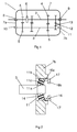
- Fig. 1 depicts schematically a gearwheel gearbox 1 for a vehicle.
- the gearwheel gearbox 1 comprises in a conventional manner a mainshaft 2 and, arranged parallel with the latter, a countershaft 3.
- the mainshaft 2 is provided with a number of gearwheels 4 and the countershaft 3 is likewise provided with a number of gearwheels 5.
- the gearwheels 4, 5 are mounted in pairs on the respective shafts 2, 3.
- the number of gearwheels 4, 5 arranged in pairs depends on the number of shafts in the gearbox 1.
- the mainshaft 2 comprises not only the gearwheels 4 but also a number of synchronising devices 6, one of which is depicted, catering for engagement and disengagement of the gears in the gearbox 1.
- a housing 7 constitutes an enclosing casing for the gearbox 1.
- the mainshaft 2 is supported in the endwalls 7a, b of the housing 7 by means of bearings 8, 9.
- the countershaft 3 is supported in the endwalls 7a, b of the housing 7 by means of bearings 10, 11.
- An intermediate reverse gear shaft 12, which is used when a reverse gear is engaged, is fastened in an aperture 13 in the endwall 7b.
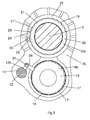
- Fig. 2 depicts in more detail the fastening of the countershaft 3 in the endwall 7b.
- the endwall 7b has an aperture 14 for accommodating an end portion of the countershaft 3 which is fitted in the aperture 14 by means of a tapered rolling bearing 11.
- the rolling bearing 11 comprises an inner bearing race 11a, an outer bearing race 11band a number of intermediate rollers 11c.
- the inner bearing race 11a is pressed firmly onto the countershaft 3 in a suitable manner.
- the inner bearing race 11a and the rollers 11c thus accompany in an axial direction any changes of length of the countershaft 3 which occur at varying temperatures.
- a first ring screw 16 is applied externally about the bearing race 11b in the aperture 14.
- the ring screw 16 thus constitutes a delineating surface which limits outward movement of the bearing race 11b in an axial direction.
- the ring screw 16 comprises a tubular portion 16a provided with external threads so that it can be screwed into correspondingly shaped internal threads on a delineating surface in the aperture 14.
- the ring screw 16 also comprises an external gripping portion 16b by means of which the screwing movement is applied.
- the outer gripping portion 16b is provided with a multiplicity of recesses 17 along a peripheral surface. There are protruding portions 17' between adjacent recesses 17.
- the ring screw 16 is adapted to being screwed into the aperture 14 until play as desired is provided for the bearing race 11b.
- the outer bearing race 11b can thus move in an axial direction within a limited range. The outer bearing race 11b therefore accompanies the other parts of the bearing 11 whenever the latter moves in an axial direction due to a change in length of the countershaft 3.
- Fig. 3 depicts the right endwall 7b of the gearbox 1 as seen from outside. It shows the first ring screw 16 provided with uniformly shaped recesses 17 which extend round the peripheral surface of the gripping portion 16b at constant spacing.
- the endwall 7b comprises an aperture 19 for supporting the mainshaft 2. It is likewise necessary that any changes in length which the mainshaft 2 undergoes due to varying temperatures be absorbed without affecting the function of the gearbox.
- the mainshaft 2 also has therein a bearing corresponding in principle to that of the countershaft 3.
- a second ring screw 20 is arranged in the aperture 19.
- the second ring screw 20 likewise comprises a threaded portion which can be screwed into correspondingly shaped threads in the aperture 19.
- the ring screw 20 comprises an external gripping portion 20b provided with a peripheral surface with a multiplicity of uniformly shaped recesses 21 which extend round the peripheral surface at constant spacing and between which the peripheral surface forms protruding portions 21'.
- the endwall 7b has a protruding annular portion 22 which extends round the hole 19.
- Two threaded holes 23 each surrounded by a planar milled surface 24 are provided in the annular portion 22.
- One of the holes 23 is visible in Figs. 3 and 4, and a bolt 25 with a washer 26 is applied in the other hole 23.
- the two holes 23 are mutually situated in such a way that when one hole 23 is substantially exactly radially external to a recess 21 of the ring screw 20, the other hole 23 is radially external to a protruding portion 21'.
- the shape of the washer 26 is such that part of it can be inserted to fit positively by shape in any desired recess 21.
- the bolt 25 is applied in whichever of the holes 23 results in the least adjustment of the rotational position of the ring screw 20 from a desired position for inserting the washer 26 in a recess 21.
- the ring screw 20 can thus be locked in two fixed rotational positions per recess 21 per revolution of the ring screw 20.
- This method of locking a ring screw by means of a bolt and a washer is already known and is also used for locking the ring screw 16 which adjusts the bearing play of the countershaft 3.
- a problem here is that the gearbox endwall 7b adjacent to the aperture 14 for the countershaft 3 is relatively sensitive from the strength point of view. It is therefore desirable to avoid mechanical processing of the endwall 7b in this area in the form of machining of two threaded holes and milled planar surfaces to provide alternative fastenings for the bolt 25 and the washer 26.
- a locking device is used instead for locking the ring screw 16 in a desired rotational position.
- the locking device comprises a locking element 28 depicted separately in Fig. 5.
- the locking element 28 comprises a base portion 28a which has a hole 29 running through it.
- the base portion 28a has extending from it a locking portion 28b which has a peripheral locking surface 28c.
- the locking surface 28c comprises two convex areas 28c' and an intermediate concave area 28c".
- the base portion 28a has extending from it in another direction an abutting portion 28d which has a peripheral abutting surface 28e.
- the locking element 28 is adapted to being fixed in a stationary position relative to the endwall 7b by means of a bolt 30 applied through the hole 29.
- the base portion 28a with said hole 29 for accommodating the bolt 30 can be situated at a distance from the aperture 14 in an area where the end portion 7b is less sensitive.
- the endwall 7b thus has an aperture 13 for accommodating an end portion of the intermediate reverse gear shaft 12.
- a recess 12a is made here in a peripheral surface of the intermediate reverse gear shaft 12 to form a substantially planar bottom surface with the purpose of constituting a stop surface 12b.
- the stop surface 12b is intended to come into contact with the locking element's planar abutting surface 28e.
- the recess 12a is situated at a distance from the outer end surface of the intermediate reverse gear shaft 12.
- the recess 13a is thus also provided with two radial side surfaces 13c.
- the locking element 28 is fastened to the endwall 7b by means of the bolt 30.
- the locking element's locking surface 28c is applied so that the two convex areas 28c' project the same recess 17 as depicted in Fig. 3 or into two adjacent recesses 17, while at the same time the concave area 28c" accommodates the protruding portion 17' situated between the two recesses 17', as depicted in Fig. 4.
- the result is the same number of fixed locking positions for the ring screw 16 with the locking element 28 as with a conventional locking device comprising a washer 26 which is fastened with a bolt 25 in one of two possible holes 23.
- the locking element 28 is fastened in a position such that the abutting surface 28e comes into contact with the stop surface 12b in the recess 13a. There is thus assurance that the locking element 28 will not rotate about the bolt 30 and that the locking of the ring screw 16 cannot slacken.
- the contact of the abutting surface 28e with the stop surface 12b provides assurance that the intermediate reverse gear shaft 12 will not perform any rotary movements in the aperture 13 when the gearwheel mounted for rotation on the intermediate reverse gear shaft 12 rotates. Unnecessary wear of the intermediate reverse gear shaft 12 is thus prevented.
- the fact that the recess 12a comprises radial side surfaces 12c also effectively prevents axial movement of the intermediate reverse gear shaft 12 in the aperture 13.
- the locking device may be used for locking in a rotational position substantially any desired turnable means which has a peripheral surface with a multiplicity of recesses.
- the locking device according to the invention may of course be applied in such a way that instead of locking the ring screw for the countershaft it locks the ring screw for the mainshaft.
- the locking element may also be provided with two or more locking portions and two or more abutting portions for locking two or more turnable means simultaneously.
Landscapes
- Engineering & Computer Science (AREA)
- General Engineering & Computer Science (AREA)
- Mechanical Engineering (AREA)
- Mounting Of Bearings Or Others (AREA)
- Snaps, Bayonet Connections, Set Pins, And Snap Rings (AREA)
- Clamps And Clips (AREA)
- Lock And Its Accessories (AREA)
- Rolling Contact Bearings (AREA)
- Driving Mechanisms And Operating Circuits Of Arc-Extinguishing High-Tension Switches (AREA)
Abstract
Description
- The present invention relates to a locking device for locking a turnable means according to the preamble of claim 1.
- The function of a gearbox in a vehicle needs to be maintained with unchanged quality despite varying operating conditions. It is therefore necessary that it be possible for the changes in length which gearbox shafts undergo due to varying temperatures to be absorbed without affecting gearbox function. Many gearboxes therefore have axial play in the bearings of their mainshaft and countershaft so that such shaft length changes can be absorbed.
- Such axial play may be catered for by at least one out of the respective mainshaft and countershaft bearings being provided with an axially movable bearing race. The respective mainshaft and countershaft bearings are usually applied in apertures in an endwall of the gearbox. In such cases the respective movable bearing races are during operation enabled to reposition themselves in said apertures by axial play defined by the position of a so-called ring screw applied from the outside of the gearbox. The ring screw comprises an external gripping portion for turning the ring screw and a tubular portion with external threads intended to be screwed into correspondingly shaped internal threads in the aperture.
- A locking device is usually used for locking the ring screw in the rotational position which results in the desired amount of play. A conventional such locking device comprises a washer fastened by means of a bolt in one of two holes provided adjacent to the aperture in the endwall. The gripping portion of each ring screw comprises a multiplicity of recesses evenly distributed along a peripheral surface. In the fitted state of the locking device, the washer fits positively by shape into one of the recesses and locks the ring screw. The bolt is applied in one of the two holes whereby the washer can be inserted in a recess with the least possible adjustment of the rotational position of the ring screw. The ring screw can thus be locked in a relatively large number of fixed rotational positions per revolution. The axial play desired for the movable bearing race can thus be provided with good accuracy. The gearbox endwall is relatively sensitive from the strength point of view, at least in the vicinity of the aperture for the countershaft. It would therefore be desirable not to have to drill two holes and mill planar surfaces round the holes in this area, operations which are necessary for fastening the known locking device.
- One object of the present invention is to provide a locking device which can in a functional manner lock in a large number of fixed rotational positions a turnable means which comprises peripheral recesses, while at the same time the locking device can be fastened with reduced machining of the area adjacent to the turning means.
- This object is achieved with a locking element of the kind mentioned in the introduction which is characterised by the features indicated in the characterising part of claim 1. The locking device thus comprises a locking element with a locking surface so shaped that it can be inserted in any desired recess of the turnable means. Such a locking surface makes it possible to lock the turnable means in one rotational position per recess per revolution. The locking surface of the locking element is thus also so shaped as to enable it to accommodate the protruding portions inevitably present between adjacent recesses. Such an accommodating locking surface also makes it possible to lock the turnable means in one further rotational position per protruding portion per revolution. The locking element can thus lock the turnable means in two rotational positions per recess per revolution. Such a locking element thus provides a locking capacity corresponding to that of a conventional locking device which has a washer applicable in one of two possible holes by the means of a bolt. In contrast, the locking element according to the present invention need only be applicable in one position. Said fastener can thus provide for application of the locking element by means of, for example, only one hole. A suitably shaped locking element enables this hole to be situated at a distance from the sensitive area which is immediately adjacent to the turnable means.
- According to a preferred embodiment of the invention, said locking surface comprises two convex areas and an intermediate concave area. The convex areas may be so shaped that they each fill the side region of the recess when they are in an inserted state. The locking surface can thus be inserted in each of said recesses in order to lock the turnable means. The presence of the concave area between the convex areas does not reduce the ability of the locking element to lock the turnable means when locking engagement between the locking surface and the recess is substantially effected at the side regions of the recess. The concave area has with advantage a concave shape which continues the shape of the protruding portions of the turnable means. The concave area can thus accommodate and grip any desired protruding portion situated between two recesses so that the turnable means is locked in a rotational position defined by the position of the protruding portion.
- According to another preferred embodiment of the present invention, the locking element has running through it a hole whereby a fastener in the form of a fastening means is adapted to being applied through said hole in order to fasten the locking element to a surface. With a fastening means in the form of a bolt, only one threaded hole need be applied in said surface for accommodating the fastening means and the fastened locking element. The locking element may comprise a base portion provided with said hole for accommodating the fastening means, and a locking portion which protrudes from the base portion and has a peripheral surface which comprises said locking surface. A locking portion of suitable extent makes it possible for the hole for accommodating the fastening means to be applied at a distance from the turnable means. Said hole can thus be applied in a less sensitive area from the strength point of view. With advantage, said fastener comprises a stop surface against which an abutting surface of the locking element is adapted to being applied to prevent rotary movement of the locking element about the fastening means. There is thus assurance that the locking element will remain in a stationary position, which is likely to be a prerequisite for the locking element to be able to provide secure locking of the turnable means. The locking element may comprise an abutting portion which protrudes from the base portion and has a peripheral surface which comprises said abutting surface. The length of the abutting portion and its extent in a direction away from the base portion are such that the abutting surface comes into contact with a suitable stationary stop surface. With advantage, said stop surface is a suitably situated surface adjacent to the turnable means.
- According to another preferred embodiment of the present invention, the turnable means is an annular screw means which can be screwed into an aperture with delineating surfaces which are provided with threads whereby the locking element is adapted to locking the screw means in a rotational position which corresponds to a desired axially inserted position of the screw means in the aperture. As a screw means, in a fitted state, is limited to following a helical path, it is possible to lock a screw means in a desired axial position by locking the screw means in a corresponding rotational position. Said aperture may be accommodated in an endwall of a gearbox and the annular screw means may be adapted to adjusting axial play for a movable bearing race of a bearing which supports a rotatable shaft in the gearbox. Axial play as desired for the movable bearing race can be provided by locking the annular screw means in a particular rotational position by means of the locking element. The bearing race is with advantage an outer bearing race for a bearing which supports a mainshaft or a countershaft in the gearbox. Such a movable bearing race makes it possible for a certain amount of shaft length change to be acceptable without reducing gearbox function.
According to another preferred embodiment of the present invention, the abutting surface of the locking element is adapted to being applied to a stop surface of a non-rotatable shaft in the gearbox. With advantage, this shaft is an intermediate reverse gear shaft. The intermediate reverse gear shaft, which is used when reversing a vehicle, is usually fastened in an aperture in the gearbox in the vicinity of the apertures for the mainshaft and the countershaft. An intermediate reverse gear shaft usually has no locking device to prevent the shaft repositioning itself in the aperture. The intermediate reverse gear shaft may therefore be subject to rotary movements in the aperture when the gearwheel carried by the shaft rotates. In such cases the intermediate reverse gear shaft is liable to unnecessary wear. The non-rotatable shaft may be fastened in an aperture in the gearbox endwall whereby said stop surface is comprised within a recess which has side surfaces intended to prevent axial movement of the bearing in said aperture. As well as locking the annular means in a rotational position, the locking device thus also prevents said shaft, which may be an intermediate reverse gear shaft, not only from rotating in the aperture but also from moving in an axial direction. - A preferred embodiment of the invention is described below by way of example with reference to the attached drawings, in which:
- Fig. 1
- depicts schematically a gearwheel gearbox,
- Fig. 2
- depicts the fastening of a countershaft in the gearbox,
- Fig. 3
- depicts an endwall of the gearbox which is provided with a locking device according to the present invention,
- Fig. 4
- depicts a view corresponding to Fig. 3 but with the locking element in a different position.
- Fig. 5
- depicts a separate view of the locking element and
- Fig. 6
- depicts the fastening of an intermediate reverse gear shaft in the gearbox.
- Fig. 1 depicts schematically a gearwheel gearbox 1 for a vehicle. The gearwheel gearbox 1 comprises in a conventional manner a
mainshaft 2 and, arranged parallel with the latter, acountershaft 3. Themainshaft 2 is provided with a number ofgearwheels 4 and thecountershaft 3 is likewise provided with a number ofgearwheels 5. Thegearwheels respective shafts gearwheels mainshaft 2 comprises not only thegearwheels 4 but also a number ofsynchronising devices 6, one of which is depicted, catering for engagement and disengagement of the gears in the gearbox 1. Ahousing 7 constitutes an enclosing casing for the gearbox 1. Themainshaft 2 is supported in theendwalls 7a, b of thehousing 7 by means ofbearings countershaft 3 is supported in theendwalls 7a, b of thehousing 7 by means ofbearings reverse gear shaft 12, which is used when a reverse gear is engaged, is fastened in anaperture 13 in theendwall 7b. - Fig. 2 depicts in more detail the fastening of the
countershaft 3 in theendwall 7b. Theendwall 7b has anaperture 14 for accommodating an end portion of thecountershaft 3 which is fitted in theaperture 14 by means of a tapered rollingbearing 11. The rollingbearing 11 comprises aninner bearing race 11a, an outer bearing race 11band a number ofintermediate rollers 11c. Theinner bearing race 11a is pressed firmly onto thecountershaft 3 in a suitable manner. Theinner bearing race 11a and therollers 11c thus accompany in an axial direction any changes of length of thecountershaft 3 which occur at varying temperatures. For theouter bearing race 11b to be able to move in an axial direction with theinner bearing race 11a and therollers 11c, theouter bearing race 11b needs to be fitted with axial play in theaperture 14. To provide suitable play for theouter bearing race 11b, afirst ring screw 16 is applied externally about thebearing race 11b in theaperture 14. Thering screw 16 thus constitutes a delineating surface which limits outward movement of thebearing race 11b in an axial direction. Thering screw 16 comprises atubular portion 16a provided with external threads so that it can be screwed into correspondingly shaped internal threads on a delineating surface in theaperture 14. Thering screw 16 also comprises an externalgripping portion 16b by means of which the screwing movement is applied. The outergripping portion 16b is provided with a multiplicity ofrecesses 17 along a peripheral surface. There are protruding portions 17' betweenadjacent recesses 17. Thering screw 16 is adapted to being screwed into theaperture 14 until play as desired is provided for thebearing race 11b. Theouter bearing race 11b can thus move in an axial direction within a limited range. Theouter bearing race 11b therefore accompanies the other parts of thebearing 11 whenever the latter moves in an axial direction due to a change in length of thecountershaft 3. - Fig. 3 depicts the
right endwall 7b of the gearbox 1 as seen from outside. It shows thefirst ring screw 16 provided with uniformly shapedrecesses 17 which extend round the peripheral surface of thegripping portion 16b at constant spacing. Theendwall 7b comprises anaperture 19 for supporting themainshaft 2. It is likewise necessary that any changes in length which themainshaft 2 undergoes due to varying temperatures be absorbed without affecting the function of the gearbox. As well as running through theendwall 7b, themainshaft 2 also has therein a bearing corresponding in principle to that of thecountershaft 3. To provide here also axial play as desired for an undepicted outer bearing race, asecond ring screw 20 is arranged in theaperture 19. Thesecond ring screw 20 likewise comprises a threaded portion which can be screwed into correspondingly shaped threads in theaperture 19. Thering screw 20 comprises an externalgripping portion 20b provided with a peripheral surface with a multiplicity of uniformly shapedrecesses 21 which extend round the peripheral surface at constant spacing and between which the peripheral surface forms protruding portions 21'. - When the
second ring screw 20 is screwed into theaperture 19 to a position such as to provide play as desired, thering screw 20 needs locking. Theendwall 7b has a protrudingannular portion 22 which extends round thehole 19. Two threadedholes 23 each surrounded by a planar milledsurface 24 are provided in theannular portion 22. One of theholes 23 is visible in Figs. 3 and 4, and abolt 25 with awasher 26 is applied in theother hole 23. The twoholes 23 are mutually situated in such a way that when onehole 23 is substantially exactly radially external to arecess 21 of thering screw 20, theother hole 23 is radially external to a protruding portion 21'. The shape of thewasher 26 is such that part of it can be inserted to fit positively by shape in any desiredrecess 21. Thebolt 25 is applied in whichever of theholes 23 results in the least adjustment of the rotational position of thering screw 20 from a desired position for inserting thewasher 26 in arecess 21. Thering screw 20 can thus be locked in two fixed rotational positions perrecess 21 per revolution of thering screw 20. This method of locking a ring screw by means of a bolt and a washer is already known and is also used for locking thering screw 16 which adjusts the bearing play of thecountershaft 3. A problem here is that thegearbox endwall 7b adjacent to theaperture 14 for thecountershaft 3 is relatively sensitive from the strength point of view. It is therefore desirable to avoid mechanical processing of theendwall 7b in this area in the form of machining of two threaded holes and milled planar surfaces to provide alternative fastenings for thebolt 25 and thewasher 26. - According to the present invention, a locking device is used instead for locking the
ring screw 16 in a desired rotational position. The locking device comprises a lockingelement 28 depicted separately in Fig. 5. The lockingelement 28 comprises abase portion 28a which has ahole 29 running through it. Thebase portion 28a has extending from it a lockingportion 28b which has aperipheral locking surface 28c. The lockingsurface 28c comprises twoconvex areas 28c' and an intermediateconcave area 28c". Thebase portion 28a has extending from it in another direction an abuttingportion 28d which has a peripheralabutting surface 28e. The lockingelement 28 is adapted to being fixed in a stationary position relative to theendwall 7b by means of abolt 30 applied through thehole 29. All that is thus needed here is the creation of a threaded hole in theendwall 7b for fastening the lockingelement 28. With a lockingportion 28b of suitable length, thebase portion 28a with saidhole 29 for accommodating thebolt 30 can be situated at a distance from theaperture 14 in an area where theend portion 7b is less sensitive. Theendwall 7b thus has anaperture 13 for accommodating an end portion of the intermediatereverse gear shaft 12. Arecess 12a is made here in a peripheral surface of the intermediatereverse gear shaft 12 to form a substantially planar bottom surface with the purpose of constituting astop surface 12b. Thestop surface 12b is intended to come into contact with the locking element's planarabutting surface 28e. In Fig. 6 it is also discernible that therecess 12a is situated at a distance from the outer end surface of the intermediatereverse gear shaft 12. The recess 13a is thus also provided with two radial side surfaces 13c. - When the
first ring screw 16 has been screwed into theaperture 14 to an axial position such that theouter bearing race 11b is provided with play as desired, the lockingelement 28 is fastened to theendwall 7b by means of thebolt 30. Depending on the rotational position of thering screw 16, the locking element'slocking surface 28c is applied so that the twoconvex areas 28c' project thesame recess 17 as depicted in Fig. 3 or into twoadjacent recesses 17, while at the same time theconcave area 28c" accommodates the protruding portion 17' situated between the two recesses 17', as depicted in Fig. 4. The result is the same number of fixed locking positions for thering screw 16 with the lockingelement 28 as with a conventional locking device comprising awasher 26 which is fastened with abolt 25 in one of twopossible holes 23. The lockingelement 28 is fastened in a position such that theabutting surface 28e comes into contact with thestop surface 12b in the recess 13a. There is thus assurance that the lockingelement 28 will not rotate about thebolt 30 and that the locking of thering screw 16 cannot slacken. At the same time, the contact of theabutting surface 28e with thestop surface 12b provides assurance that the intermediatereverse gear shaft 12 will not perform any rotary movements in theaperture 13 when the gearwheel mounted for rotation on the intermediatereverse gear shaft 12 rotates. Unnecessary wear of the intermediatereverse gear shaft 12 is thus prevented. The fact that therecess 12a comprises radial side surfaces 12c also effectively prevents axial movement of the intermediatereverse gear shaft 12 in theaperture 13. - The invention is in no way limited to the embodiment described in the drawings but may be varied freely within the scopes of the claims. The locking device may be used for locking in a rotational position substantially any desired turnable means which has a peripheral surface with a multiplicity of recesses. The locking device according to the invention may of course be applied in such a way that instead of locking the ring screw for the countershaft it locks the ring screw for the mainshaft. The locking element may also be provided with two or more locking portions and two or more abutting portions for locking two or more turnable means simultaneously.
Claims (10)
- A locking device for locking a turnable means (16) which comprises a peripheral surface with a multiplicity of recesses (17), whereby the locking device comprises a locking element (28) with a locking surface (28c) so shaped that it can be inserted in any desired recess (17) of the turnable means in order to lock the turnable means (16) in a rotational position defined by the position of said recess (17), and fasteners (12b, 30) adapted to fixing the locking element (28) in a stationary position, characterised in that said locking surface (28c) is also shaped to accommodate any desired one of the projecting portions (17') which are present between adjacent recesses (17), in which accommodating state it locks the turnable means (16) in a rotational position defined by the position of said protruding portion (17').
- A locking device according to claim 1, characterised in that said locking surface (28c) comprises two convex areas (28c') and an intermediate concave area (28c").
- A locking device according to claim 1 or 2, characterised in that the locking element (28) comprises a hole (29) through which a fastener in the form of a fastening means (30) is adapted to being applied in order to fasten the locking element (28) to a surface (7b).
- A locking device according to claim 3, characterised in that the locking element (28) comprises a base portion (28a) provided with said hole (29), and a locking portion (28b) which protrudes from the base portion (28a) and which has a peripheral surface constituting said locking surface (28c).
- A locking device according to claim 3 or 4, characterised in that said fastener comprises a stationary stop surface (12b) to which an abutting surface (28e) of the locking element (28) is adapted to being applied so that rotary movement of the locking element (28) about the fastening means (30) is prevented.
- A locking device according to claim 5, characterised in that the locking element (28) comprises an abutting portion (28d) which protrudes from the base portion (28) and which has a peripheral surface constituting said abutting surface (28e).
- A locking device according to any one of the foregoing claims, characterised in that the turnable means is an annular screw means (16) which can be screwed into an aperture (14) with delineating surfaces provided with threads, and the locking element (28) is adapted to locking the screw means (16) in a rotational position corresponding to a desired inserted axial position of the screw means (16) in the aperture (14).
- A locking device according to claim 7, characterised in that said aperture (14) is arranged in an endwall (7b) of a gearbox (1) and that the annular screw means (16) is adapted to adjusting axial play for a movable bearing race (11b) of a bearing (11) which supports a rotatable shaft (3) in the gearbox (1).
- A locking device according to claims 5 and 8, characterised in that the locking element's abutting surface (28e) is adapted to being applied to a stop surface (12b) of a non-rotatable shaft (12) in the gearbox (1).
- A locking device according to claim 9, characterised in that the non-rotatable shaft (12) is fastened in an aperture (13) in an endwall (7b) of the gearbox, and said stop surface (12b) is comprised within a recess (12b) which has side surfaces (12c) adapted to preventing axial movements of the shaft (12) in said aperture (13).
Applications Claiming Priority (2)
| Application Number | Priority Date | Filing Date | Title |
|---|---|---|---|
| SE3032984 | 2003-12-09 | ||
| SE0303298A SE0303298L (en) | 2003-12-09 | 2003-12-09 | Locking device for locking a rotatable member |
Publications (2)
| Publication Number | Publication Date |
|---|---|
| EP1541899A1 true EP1541899A1 (en) | 2005-06-15 |
| EP1541899B1 EP1541899B1 (en) | 2008-09-03 |
Family
ID=29997671
Family Applications (1)
| Application Number | Title | Priority Date | Filing Date |
|---|---|---|---|
| EP04105435A Expired - Lifetime EP1541899B1 (en) | 2003-12-09 | 2004-11-01 | Locking device for locking a turnable means |
Country Status (6)
| Country | Link |
|---|---|
| EP (1) | EP1541899B1 (en) |
| AT (1) | ATE407309T1 (en) |
| BR (1) | BRPI0405135B1 (en) |
| DE (1) | DE602004016270D1 (en) |
| ES (1) | ES2312927T3 (en) |
| SE (1) | SE0303298L (en) |
Cited By (1)
| Publication number | Priority date | Publication date | Assignee | Title |
|---|---|---|---|---|
| CN114824858A (en) * | 2021-01-29 | 2022-07-29 | 康哲电脑配件(吴江)有限公司 | Holder for electronic device |
Citations (4)
| Publication number | Priority date | Publication date | Assignee | Title |
|---|---|---|---|---|
| US1512402A (en) * | 1919-07-12 | 1924-10-21 | Clark Equipment Co | Axle for motor vehicles |
| US1556875A (en) * | 1923-11-12 | 1925-10-13 | Gen Motors Corp | Differential carrier |
| EP0522739A1 (en) * | 1991-07-10 | 1993-01-13 | Eaton Corporation | Transmission countershaft rotary bearing shim |
| US6532660B1 (en) * | 2000-09-14 | 2003-03-18 | Torque-Traction Technologies, Inc. | Backlash adjuster with bevel gear face for adjustment with mating geared tool |
-
2003
- 2003-12-09 SE SE0303298A patent/SE0303298L/en not_active IP Right Cessation
-
2004
- 2004-11-01 DE DE602004016270T patent/DE602004016270D1/en not_active Expired - Lifetime
- 2004-11-01 ES ES04105435T patent/ES2312927T3/en not_active Expired - Lifetime
- 2004-11-01 EP EP04105435A patent/EP1541899B1/en not_active Expired - Lifetime
- 2004-11-01 AT AT04105435T patent/ATE407309T1/en not_active IP Right Cessation
- 2004-11-23 BR BRPI0405135A patent/BRPI0405135B1/en active IP Right Grant
Patent Citations (4)
| Publication number | Priority date | Publication date | Assignee | Title |
|---|---|---|---|---|
| US1512402A (en) * | 1919-07-12 | 1924-10-21 | Clark Equipment Co | Axle for motor vehicles |
| US1556875A (en) * | 1923-11-12 | 1925-10-13 | Gen Motors Corp | Differential carrier |
| EP0522739A1 (en) * | 1991-07-10 | 1993-01-13 | Eaton Corporation | Transmission countershaft rotary bearing shim |
| US6532660B1 (en) * | 2000-09-14 | 2003-03-18 | Torque-Traction Technologies, Inc. | Backlash adjuster with bevel gear face for adjustment with mating geared tool |
Cited By (1)
| Publication number | Priority date | Publication date | Assignee | Title |
|---|---|---|---|---|
| CN114824858A (en) * | 2021-01-29 | 2022-07-29 | 康哲电脑配件(吴江)有限公司 | Holder for electronic device |
Also Published As
| Publication number | Publication date |
|---|---|
| BRPI0405135A (en) | 2005-08-30 |
| EP1541899B1 (en) | 2008-09-03 |
| ES2312927T3 (en) | 2009-03-01 |
| BRPI0405135B1 (en) | 2016-12-13 |
| ATE407309T1 (en) | 2008-09-15 |
| SE0303298D0 (en) | 2003-12-09 |
| DE602004016270D1 (en) | 2008-10-16 |
| SE524978C2 (en) | 2004-11-02 |
| SE0303298L (en) | 2004-11-02 |
Similar Documents
| Publication | Publication Date | Title |
|---|---|---|
| US4210372A (en) | Retainer for bearing lock nut | |
| JP3201640U (en) | Swivel drive | |
| US4718291A (en) | Devices for converting rotary movement into linear movement | |
| EP0571565B1 (en) | Bearing for mounting on a multi-sided shaft | |
| US4248487A (en) | Rolling bearing | |
| US4592247A (en) | Continually adjustable ball-type planetary gear set | |
| US6367980B1 (en) | Ultra thin type rolling bearing and cage therefor | |
| JP2006118709A (en) | Axle assembly with bearing adjustment mechanism | |
| US5117706A (en) | Backlash-free drive for the infeed mechanism of a microtome | |
| KR102359207B1 (en) | Gear apparatus | |
| CA2589064A1 (en) | Bearing and method whereby such a bearing can be applied | |
| US9291254B2 (en) | Disengaging gear unit | |
| GB2036240A (en) | Variable ratio rack and pinion gear | |
| EP1541899B1 (en) | Locking device for locking a turnable means | |
| WO1996018827A1 (en) | Bearing having multi-sided inner ring bore with elastomeric rings | |
| US4920817A (en) | Ball screw with screw cage in raceway ring of nut | |
| US4433875A (en) | Torque transmitting bearing and method of assembly | |
| EP0522739B1 (en) | Transmission countershaft rotary bearing shim | |
| US20030210841A1 (en) | Bearing seat | |
| US4926714A (en) | Gear selector for bicycle hub transmission | |
| EP1461543B1 (en) | Screw actuator module | |
| WO2002093038A1 (en) | Automotive differential | |
| US20210140489A1 (en) | Spline structure, speed-reducing or -increasing apparatus, and constant-velocity joint | |
| DE60309610T2 (en) | Drum machine with sensor arrangement for measuring the rotational parameters of the drum | |
| SU1679090A1 (en) | Gear shift mechanism |
Legal Events
| Date | Code | Title | Description |
|---|---|---|---|
| PUAI | Public reference made under article 153(3) epc to a published international application that has entered the european phase |
Free format text: ORIGINAL CODE: 0009012 |
|
| AK | Designated contracting states |
Kind code of ref document: A1 Designated state(s): AT BE BG CH CY CZ DE DK EE ES FI FR GB GR HU IE IS IT LI LU MC NL PL PT RO SE SI SK TR |
|
| AX | Request for extension of the european patent |
Extension state: AL HR LT LV MK YU |
|
| 17P | Request for examination filed |
Effective date: 20051215 |
|
| AKX | Designation fees paid |
Designated state(s): AT BE BG CH CY CZ DE DK EE ES FI FR GB GR HU IE IS IT LI LU MC NL PL PT RO SE SI SK TR |
|
| GRAP | Despatch of communication of intention to grant a patent |
Free format text: ORIGINAL CODE: EPIDOSNIGR1 |
|
| GRAS | Grant fee paid |
Free format text: ORIGINAL CODE: EPIDOSNIGR3 |
|
| GRAA | (expected) grant |
Free format text: ORIGINAL CODE: 0009210 |
|
| AK | Designated contracting states |
Kind code of ref document: B1 Designated state(s): AT BE BG CH CY CZ DE DK EE ES FI FR GB GR HU IE IS IT LI LU MC NL PL PT RO SE SI SK TR |
|
| REG | Reference to a national code |
Ref country code: GB Ref legal event code: FG4D |
|
| REG | Reference to a national code |
Ref country code: CH Ref legal event code: EP |
|
| REG | Reference to a national code |
Ref country code: IE Ref legal event code: FG4D |
|
| REF | Corresponds to: |
Ref document number: 602004016270 Country of ref document: DE Date of ref document: 20081016 Kind code of ref document: P |
|
| REG | Reference to a national code |
Ref country code: DE Ref legal event code: R096 Ref document number: 602004016270 Country of ref document: DE Effective date: 20081016 |
|
| PG25 | Lapsed in a contracting state [announced via postgrant information from national office to epo] |
Ref country code: NL Free format text: LAPSE BECAUSE OF FAILURE TO SUBMIT A TRANSLATION OF THE DESCRIPTION OR TO PAY THE FEE WITHIN THE PRESCRIBED TIME-LIMIT Effective date: 20080903 |
|
| PG25 | Lapsed in a contracting state [announced via postgrant information from national office to epo] |
Ref country code: AT Free format text: LAPSE BECAUSE OF FAILURE TO SUBMIT A TRANSLATION OF THE DESCRIPTION OR TO PAY THE FEE WITHIN THE PRESCRIBED TIME-LIMIT Effective date: 20080903 Ref country code: SI Free format text: LAPSE BECAUSE OF FAILURE TO SUBMIT A TRANSLATION OF THE DESCRIPTION OR TO PAY THE FEE WITHIN THE PRESCRIBED TIME-LIMIT Effective date: 20080903 Ref country code: FI Free format text: LAPSE BECAUSE OF FAILURE TO SUBMIT A TRANSLATION OF THE DESCRIPTION OR TO PAY THE FEE WITHIN THE PRESCRIBED TIME-LIMIT Effective date: 20080903 |
|
| PGFP | Annual fee paid to national office [announced via postgrant information from national office to epo] |
Ref country code: ES Payment date: 20081205 Year of fee payment: 5 |
|
| REG | Reference to a national code |
Ref country code: ES Ref legal event code: FG2A Ref document number: 2312927 Country of ref document: ES Kind code of ref document: T3 |
|
| NLV1 | Nl: lapsed or annulled due to failure to fulfill the requirements of art. 29p and 29m of the patents act | ||
| PG25 | Lapsed in a contracting state [announced via postgrant information from national office to epo] |
Ref country code: BE Free format text: LAPSE BECAUSE OF FAILURE TO SUBMIT A TRANSLATION OF THE DESCRIPTION OR TO PAY THE FEE WITHIN THE PRESCRIBED TIME-LIMIT Effective date: 20080903 |
|
| PGFP | Annual fee paid to national office [announced via postgrant information from national office to epo] |
Ref country code: IT Payment date: 20081129 Year of fee payment: 5 |
|
| PG25 | Lapsed in a contracting state [announced via postgrant information from national office to epo] |
Ref country code: BG Free format text: LAPSE BECAUSE OF FAILURE TO SUBMIT A TRANSLATION OF THE DESCRIPTION OR TO PAY THE FEE WITHIN THE PRESCRIBED TIME-LIMIT Effective date: 20081203 |
|
| PGFP | Annual fee paid to national office [announced via postgrant information from national office to epo] |
Ref country code: FR Payment date: 20081128 Year of fee payment: 5 |
|
| PG25 | Lapsed in a contracting state [announced via postgrant information from national office to epo] |
Ref country code: RO Free format text: LAPSE BECAUSE OF FAILURE TO SUBMIT A TRANSLATION OF THE DESCRIPTION OR TO PAY THE FEE WITHIN THE PRESCRIBED TIME-LIMIT Effective date: 20080903 Ref country code: SK Free format text: LAPSE BECAUSE OF FAILURE TO SUBMIT A TRANSLATION OF THE DESCRIPTION OR TO PAY THE FEE WITHIN THE PRESCRIBED TIME-LIMIT Effective date: 20080903 Ref country code: PT Free format text: LAPSE BECAUSE OF FAILURE TO SUBMIT A TRANSLATION OF THE DESCRIPTION OR TO PAY THE FEE WITHIN THE PRESCRIBED TIME-LIMIT Effective date: 20090203 Ref country code: CZ Free format text: LAPSE BECAUSE OF FAILURE TO SUBMIT A TRANSLATION OF THE DESCRIPTION OR TO PAY THE FEE WITHIN THE PRESCRIBED TIME-LIMIT Effective date: 20080903 Ref country code: IS Free format text: LAPSE BECAUSE OF FAILURE TO SUBMIT A TRANSLATION OF THE DESCRIPTION OR TO PAY THE FEE WITHIN THE PRESCRIBED TIME-LIMIT Effective date: 20090103 |
|
| PG25 | Lapsed in a contracting state [announced via postgrant information from national office to epo] |
Ref country code: MC Free format text: LAPSE BECAUSE OF NON-PAYMENT OF DUE FEES Effective date: 20081130 |
|
| PGFP | Annual fee paid to national office [announced via postgrant information from national office to epo] |
Ref country code: GB Payment date: 20081112 Year of fee payment: 5 |
|
| REG | Reference to a national code |
Ref country code: CH Ref legal event code: PL |
|
| PLBE | No opposition filed within time limit |
Free format text: ORIGINAL CODE: 0009261 |
|
| STAA | Information on the status of an ep patent application or granted ep patent |
Free format text: STATUS: NO OPPOSITION FILED WITHIN TIME LIMIT |
|
| PG25 | Lapsed in a contracting state [announced via postgrant information from national office to epo] |
Ref country code: DK Free format text: LAPSE BECAUSE OF FAILURE TO SUBMIT A TRANSLATION OF THE DESCRIPTION OR TO PAY THE FEE WITHIN THE PRESCRIBED TIME-LIMIT Effective date: 20080903 Ref country code: EE Free format text: LAPSE BECAUSE OF FAILURE TO SUBMIT A TRANSLATION OF THE DESCRIPTION OR TO PAY THE FEE WITHIN THE PRESCRIBED TIME-LIMIT Effective date: 20080903 |
|
| 26N | No opposition filed |
Effective date: 20090604 |
|
| REG | Reference to a national code |
Ref country code: DE Ref legal event code: R097 Ref document number: 602004016270 Country of ref document: DE Effective date: 20090604 |
|
| PG25 | Lapsed in a contracting state [announced via postgrant information from national office to epo] |
Ref country code: CH Free format text: LAPSE BECAUSE OF NON-PAYMENT OF DUE FEES Effective date: 20081130 Ref country code: IE Free format text: LAPSE BECAUSE OF NON-PAYMENT OF DUE FEES Effective date: 20081101 Ref country code: LI Free format text: LAPSE BECAUSE OF NON-PAYMENT OF DUE FEES Effective date: 20081130 |
|
| PG25 | Lapsed in a contracting state [announced via postgrant information from national office to epo] |
Ref country code: SE Free format text: LAPSE BECAUSE OF FAILURE TO SUBMIT A TRANSLATION OF THE DESCRIPTION OR TO PAY THE FEE WITHIN THE PRESCRIBED TIME-LIMIT Effective date: 20081203 |
|
| PG25 | Lapsed in a contracting state [announced via postgrant information from national office to epo] |
Ref country code: PL Free format text: LAPSE BECAUSE OF FAILURE TO SUBMIT A TRANSLATION OF THE DESCRIPTION OR TO PAY THE FEE WITHIN THE PRESCRIBED TIME-LIMIT Effective date: 20080903 |
|
| GBPC | Gb: european patent ceased through non-payment of renewal fee |
Effective date: 20091101 |
|
| PG25 | Lapsed in a contracting state [announced via postgrant information from national office to epo] |
Ref country code: LU Free format text: LAPSE BECAUSE OF NON-PAYMENT OF DUE FEES Effective date: 20081101 Ref country code: CY Free format text: LAPSE BECAUSE OF FAILURE TO SUBMIT A TRANSLATION OF THE DESCRIPTION OR TO PAY THE FEE WITHIN THE PRESCRIBED TIME-LIMIT Effective date: 20080903 Ref country code: HU Free format text: LAPSE BECAUSE OF FAILURE TO SUBMIT A TRANSLATION OF THE DESCRIPTION OR TO PAY THE FEE WITHIN THE PRESCRIBED TIME-LIMIT Effective date: 20090304 |
|
| REG | Reference to a national code |
Ref country code: FR Ref legal event code: ST Effective date: 20100730 |
|
| PG25 | Lapsed in a contracting state [announced via postgrant information from national office to epo] |
Ref country code: TR Free format text: LAPSE BECAUSE OF FAILURE TO SUBMIT A TRANSLATION OF THE DESCRIPTION OR TO PAY THE FEE WITHIN THE PRESCRIBED TIME-LIMIT Effective date: 20080903 |
|
| PG25 | Lapsed in a contracting state [announced via postgrant information from national office to epo] |
Ref country code: GR Free format text: LAPSE BECAUSE OF FAILURE TO SUBMIT A TRANSLATION OF THE DESCRIPTION OR TO PAY THE FEE WITHIN THE PRESCRIBED TIME-LIMIT Effective date: 20081204 Ref country code: FR Free format text: LAPSE BECAUSE OF NON-PAYMENT OF DUE FEES Effective date: 20091130 |
|
| PG25 | Lapsed in a contracting state [announced via postgrant information from national office to epo] |
Ref country code: GB Free format text: LAPSE BECAUSE OF NON-PAYMENT OF DUE FEES Effective date: 20091101 |
|
| REG | Reference to a national code |
Ref country code: ES Ref legal event code: FD2A Effective date: 20110323 |
|
| PG25 | Lapsed in a contracting state [announced via postgrant information from national office to epo] |
Ref country code: IT Free format text: LAPSE BECAUSE OF NON-PAYMENT OF DUE FEES Effective date: 20091101 |
|
| PG25 | Lapsed in a contracting state [announced via postgrant information from national office to epo] |
Ref country code: ES Free format text: LAPSE BECAUSE OF NON-PAYMENT OF DUE FEES Effective date: 20110310 |
|
| PG25 | Lapsed in a contracting state [announced via postgrant information from national office to epo] |
Ref country code: ES Free format text: LAPSE BECAUSE OF NON-PAYMENT OF DUE FEES Effective date: 20091102 |
|
| P01 | Opt-out of the competence of the unified patent court (upc) registered |
Effective date: 20230518 |
|
| PGFP | Annual fee paid to national office [announced via postgrant information from national office to epo] |
Ref country code: DE Payment date: 20230929 Year of fee payment: 20 |
|
| REG | Reference to a national code |
Ref country code: DE Ref legal event code: R071 Ref document number: 602004016270 Country of ref document: DE |