EP1541898A2 - CVT transmission for motor vehicles, in particular for tractors - Google Patents
CVT transmission for motor vehicles, in particular for tractors Download PDFInfo
- Publication number
- EP1541898A2 EP1541898A2 EP04106428A EP04106428A EP1541898A2 EP 1541898 A2 EP1541898 A2 EP 1541898A2 EP 04106428 A EP04106428 A EP 04106428A EP 04106428 A EP04106428 A EP 04106428A EP 1541898 A2 EP1541898 A2 EP 1541898A2
- Authority
- EP
- European Patent Office
- Prior art keywords
- shaft
- gear
- clutch
- integral
- gear wheels
- Prior art date
- Legal status (The legal status is an assumption and is not a legal conclusion. Google has not performed a legal analysis and makes no representation as to the accuracy of the status listed.)
- Granted
Links
Images


Classifications
-
- F—MECHANICAL ENGINEERING; LIGHTING; HEATING; WEAPONS; BLASTING
- F16—ENGINEERING ELEMENTS AND UNITS; GENERAL MEASURES FOR PRODUCING AND MAINTAINING EFFECTIVE FUNCTIONING OF MACHINES OR INSTALLATIONS; THERMAL INSULATION IN GENERAL
- F16H—GEARING
- F16H3/00—Toothed gearings for conveying rotary motion with variable gear ratio or for reversing rotary motion
- F16H3/006—Toothed gearings for conveying rotary motion with variable gear ratio or for reversing rotary motion power being selectively transmitted by parallel flow paths, e.g. dual clutch transmissions
-
- F—MECHANICAL ENGINEERING; LIGHTING; HEATING; WEAPONS; BLASTING
- F16—ENGINEERING ELEMENTS AND UNITS; GENERAL MEASURES FOR PRODUCING AND MAINTAINING EFFECTIVE FUNCTIONING OF MACHINES OR INSTALLATIONS; THERMAL INSULATION IN GENERAL
- F16H—GEARING
- F16H47/00—Combinations of mechanical gearing with fluid clutches or fluid gearing
- F16H47/02—Combinations of mechanical gearing with fluid clutches or fluid gearing the fluid gearing being of the volumetric type
- F16H47/04—Combinations of mechanical gearing with fluid clutches or fluid gearing the fluid gearing being of the volumetric type the mechanical gearing being of the type with members having orbital motion
-
- F—MECHANICAL ENGINEERING; LIGHTING; HEATING; WEAPONS; BLASTING
- F16—ENGINEERING ELEMENTS AND UNITS; GENERAL MEASURES FOR PRODUCING AND MAINTAINING EFFECTIVE FUNCTIONING OF MACHINES OR INSTALLATIONS; THERMAL INSULATION IN GENERAL
- F16H—GEARING
- F16H61/00—Control functions within control units of change-speed- or reversing-gearings for conveying rotary motion ; Control of exclusively fluid gearing, friction gearing, gearings with endless flexible members or other particular types of gearing
- F16H61/04—Smoothing ratio shift
- F16H61/0403—Synchronisation before shifting
-
- F—MECHANICAL ENGINEERING; LIGHTING; HEATING; WEAPONS; BLASTING
- F16—ENGINEERING ELEMENTS AND UNITS; GENERAL MEASURES FOR PRODUCING AND MAINTAINING EFFECTIVE FUNCTIONING OF MACHINES OR INSTALLATIONS; THERMAL INSULATION IN GENERAL
- F16H—GEARING
- F16H37/00—Combinations of mechanical gearings, not provided for in groups F16H1/00 - F16H35/00
- F16H37/02—Combinations of mechanical gearings, not provided for in groups F16H1/00 - F16H35/00 comprising essentially only toothed or friction gearings
- F16H37/06—Combinations of mechanical gearings, not provided for in groups F16H1/00 - F16H35/00 comprising essentially only toothed or friction gearings with a plurality of driving or driven shafts; with arrangements for dividing torque between two or more intermediate shafts
- F16H37/08—Combinations of mechanical gearings, not provided for in groups F16H1/00 - F16H35/00 comprising essentially only toothed or friction gearings with a plurality of driving or driven shafts; with arrangements for dividing torque between two or more intermediate shafts with differential gearing
- F16H37/0833—Combinations of mechanical gearings, not provided for in groups F16H1/00 - F16H35/00 comprising essentially only toothed or friction gearings with a plurality of driving or driven shafts; with arrangements for dividing torque between two or more intermediate shafts with differential gearing with arrangements for dividing torque between two or more intermediate shafts, i.e. with two or more internal power paths
- F16H37/084—Combinations of mechanical gearings, not provided for in groups F16H1/00 - F16H35/00 comprising essentially only toothed or friction gearings with a plurality of driving or driven shafts; with arrangements for dividing torque between two or more intermediate shafts with differential gearing with arrangements for dividing torque between two or more intermediate shafts, i.e. with two or more internal power paths at least one power path being a continuously variable transmission, i.e. CVT
- F16H2037/088—Power-split transmissions with summing differentials, with the input of the CVT connected or connectable to the input shaft
-
- F—MECHANICAL ENGINEERING; LIGHTING; HEATING; WEAPONS; BLASTING
- F16—ENGINEERING ELEMENTS AND UNITS; GENERAL MEASURES FOR PRODUCING AND MAINTAINING EFFECTIVE FUNCTIONING OF MACHINES OR INSTALLATIONS; THERMAL INSULATION IN GENERAL
- F16H—GEARING
- F16H2200/00—Transmissions for multiple ratios
- F16H2200/003—Transmissions for multiple ratios characterised by the number of forward speeds
- F16H2200/0043—Transmissions for multiple ratios characterised by the number of forward speeds the gear ratios comprising four forward speeds
-
- F—MECHANICAL ENGINEERING; LIGHTING; HEATING; WEAPONS; BLASTING
- F16—ENGINEERING ELEMENTS AND UNITS; GENERAL MEASURES FOR PRODUCING AND MAINTAINING EFFECTIVE FUNCTIONING OF MACHINES OR INSTALLATIONS; THERMAL INSULATION IN GENERAL
- F16H—GEARING
- F16H2306/00—Shifting
- F16H2306/40—Shifting activities
- F16H2306/48—Synchronising of new gear
-
- F—MECHANICAL ENGINEERING; LIGHTING; HEATING; WEAPONS; BLASTING
- F16—ENGINEERING ELEMENTS AND UNITS; GENERAL MEASURES FOR PRODUCING AND MAINTAINING EFFECTIVE FUNCTIONING OF MACHINES OR INSTALLATIONS; THERMAL INSULATION IN GENERAL
- F16H—GEARING
- F16H61/00—Control functions within control units of change-speed- or reversing-gearings for conveying rotary motion ; Control of exclusively fluid gearing, friction gearing, gearings with endless flexible members or other particular types of gearing
- F16H61/38—Control of exclusively fluid gearing
- F16H61/40—Control of exclusively fluid gearing hydrostatic
- F16H61/46—Automatic regulation in accordance with output requirements
Definitions
- the present invention relates to a CVT transmission for motor vehicles, in particular for farm tractors.
- Known CVT transmissions simultaneously use a mechanical power generated by an internal combustion engine, power which is modulated in output towards the differential gear by means of a hydrostatic unit.
- the running mode shift is achieved by un-meshing a toothed mechanical coupling from a device with which a first transmission ratio is obtained and meshing another toothed mechanical coupling in a device whereby a second transmission ratio is obtained.
- the object of the present invention therefore is to provide a CVT transmission that is free from the drawbacks described above.
- CVT transmission for motor vehicles in particular for farm tractors, is provided, as defined by the characteristics of claim 1.
- the reference 10 globally designates a CVT transmission of the present invention in a first condition of engagement thereof, i.e. when the first forward running mode (I) is engaged (see below).
- the transmission 10 comprises a hydrostatic unit 11, in turn comprising a variable displacement pump 12a operatively connected to a fixed displacement motor 12b.
- the output of the variable displacement pump 12a can be adjusted by means of a swash plate (not shown) of which the position is controlled by electronic means better described below.
- the hydrostatic unit 11 in dependence of adjustment means better explained below, is operable to drive a gear wheel 13 keyed onto a transmission shaft 14.
- the gear wheel 13 meshes with a further gear wheel 15 keyed onto a shaft 16 to which another gear wheel 17 is fixedly attached.
- This arrangement of gears is operable to send the regulating motion generated by the hydrostatic unit 11 towards an epicyclic rotary mechanism globally designated by the number 18 (see below).
- An internal combustion engine 19 drives a drive shaft 20 mechanically connected directly, in traditional fashion, with a PTO of the tractor. Moreover, the drive shaft 20 drives parts of the epicyclic rotary mechanism 18. More particularly, the epicyclic rotary mechanism 18 comprises, in known fashion, a first sun gear 21 keyed directly onto the drive shaft 20. The first sun gear 21 meshes with a plurality of planet gears or satellites positioned, in conventional manner, around the first sun gear 21 (in Figure 1, only two planet gears 22 are shown).
- the epicyclic rotary mechanism 18 further comprises a spider 23 carrying the planet gears 22 and extending into a hollow shaft 24.
- a ring wheel 25 is operatively connected with the aforesaid gear wheel 17 through another gear wheel 26 whereby the hydrostatic unit 11 is mechanically connected with the epicyclic rotary mechanism 18.
- first sun gear 21 meshes with gear wheels 27 of the planet gears 22, whereas the gear wheels 28 of the satellites 22 simultaneously mesh with the ring 25 and with a second sun gear 29.
- the second sun gear 29 is keyed onto a transmission shaft 30.
- the output speed of the epicyclic rotary mechanism 18 can be modulated.
- the two output elements from the epicyclic rotary mechanism 18 are the spider 23, with the related transmission shaft 24, and the second sun gear 29 integral with the drive shaft 30.
- the hollow shaft 30 is inserted coaxially within the shaft 24, which is also hollow.
- the drive shaft 20 is housed within the shaft 30, which, as stated, is also hollow.
- the three shafts 20, 30 and 24 are mutually coaxial and inserted one inside the other.
- the shaft 24 bears three idle gear wheels 31, 32 and 33. Furthermore, a first bi-directional synchroniser S1 and a second monodirectional synchroniser S2 are fixedly connected to the shaft 24.
- the synchroniser S1 is positioned between the gear wheels 31 and 32 and is able to connect, in selective manner, either the gear wheel 31 or the gear wheel 32 to the shaft 24.
- the synchroniser S2 is operable, in selective fashion, to fixedly connect the gear wheel 33 to the transmission shaft 24, in a manner that will become more readily apparent below.
- the gear wheel 31 permanently meshes with a gear wheel 34 keyed onto a transmission shaft 35 mechanically connected with a first clutch A.
- the gear wheel 32 permanently meshes with a gear wheel 36 also keyed onto the shaft 35.
- the shaft 35 extends parallel to the shafts 20, 24 and 30.
- the shafts 24, 30 are generally in rotation for almost any condition of travel, since they take motion directly from the drive shaft 20. However, it is necessary to specify that the shaft 24 in some conditions of travel reaches zero speed.
- the clutch A is mechanically connected to a differential gear DIF by means of a motion transferring unit 37.
- the unit 37 comprises a shaft 38, integral with the output side of the clutch A, whereon a gear wheel 39 is fixedly connected.
- the gear wheel 39 meshes with a gear wheel 40 fastened to a hollow shaft 41 traversed by the drive shaft 20, which, as stated, sets the PTO in rotation.
- the shaft 41 further comprises a fixedly connected gear wheel 42 which meshes with a gear wheel 43 integral with a mechanical connection shaft 44 with a pinion 45 of the differential gear DIF.
- the presence of the motion transfer unit 37 is not indispensable and the clutch A could be connected directly to the differential DIF.
- the gear wheel 33 which, as already mentioned, is normally idle on the shaft 24, meshes with an idle gear 46, which, in turn, also meshes with a gear wheel 47 fixedly connected to a hollow transmission shaft 48 through which passes the aforesaid transmission shaft 35.
- the idle wheel 46 serves the purpose of inverting the sense of rotation of the gear wheel 47 to obtain the desired reverse running mode (see below).
- a second clutch B mechanically connected to the transmission shaft 48, is operable to transmit motion to the unit 37, and hence, finally, to the differential gear DIF.
- the clutch B is positioned "upstream" of the clutch A and, as shown for example in Figure 2, the clutches A and B are constructed such that when the clutch B is closed, motion from the epicyclic rotary mechanism 18 is transmitted to an external housing portion of the clutch A. In as much as this external housing portion is connected to shaft 38, there is a continuity of the transmission towards the differential gear DIF.
- a third bi-directional synchroniser S3, integral with the shaft 30, is inserted inbetween the gear wheels 49 and 50.
- the gear wheels 49, 50 respectively mesh with gear wheels 51 and 52, both integrally connected with the connection shaft 48, in turn connected to the outer housing of the second clutch B.
- a transmission unit 70 is employed comprising a gear wheel 71 keyed onto the drive shaft 20, and a gear wheel 72 integral with a shaft 73 mechanically connected to the pump 12a.
- a transmission device 74 is provided comprising, in turn, a shaft 75 having a first gear wheel 76 meshing with the gear wheel 71 and a second gear wheel 77 meshing with the gear wheel 72.
- Figure 1 further shows a manual control 99 actuated by an operator who, through a lever L, imparts commands to the transmission 10 to determine the engaged gear of the motor vehicle.
- the lever L is connected to an electronic unit 100, which manages the signals measured by a series of sensors Sn.
- Sn1 is the sensor that measures the angular speed of the transmission shaft 20, whilst Sn2 measures the angular speed of the ring wheel 25 of the epicyclic rotary mechanism 18.
- Sn3 controls the speed of rotation of the second sun gear 29, whilst Sn4, Sn5, and Sn6 are sensors that respectively control the position of the synchronisers S1, S2, S3.
- respective actuators (not shown) are provided.
- the sensor Sn9 measures the angular speed of the shaft 44, whilst the sensor Sn10 controls the operating conditions of the pump 12 of the hydraulic unit 11. Lastly, the sensor Sn11 detects the command imparted by the operator through the lever L.
- the unit 100 sets the general conditions of operation of the hydraulic unit 11, of the synchronisers S1, S2, S3 and of the clutches A and B in such a way as to have a condition of travel of the motor vehicle corresponding to the commands imparted by the operator by means of the lever L, obviously taking the values measures by the sensors Sn appropriately into account.
- the transmission of the motion through the gear wheels 31, 34 achieves the first forward running mode (I), whilst the transmission of the motion by means of the gear wheels 32 and 36 achieves the third forward running mode (III).
- the second forward running mode (II) and the fourth forward running mode (IV) are obtained in the transmission by means of the coupling between the gear wheels 50, 52 and, respectively, the gear wheels 49 and 51.
- the operation of the CVT transmission 10 of the present invention is the following.
- the synchroniser S1 acts on the gear wheel 31 to make it integral with the shaft 24.
- the mechanical power, generated by the internal combustion engine 19, is sent to the gear wheel 34 through the epicyclic rotary mechanism 18, which sets the transmission shaft 35 in rotation.
- the first clutch A is closed (whilst the second clutch B is open), so the mechanical power is transmitted through the clutch A to the shaft 38, to the unit 37 and hence to the differential gear DIF.
- the synchroniser S3 acts on the gear wheel 50 to make it integral with the transmission shaft 30. This action sets the gear wheel 52 into rotation, and as it meshes with the gear wheel 50, also the transmission shaft 48 starts to rotate. No power is transmitted to the differential gear DIF however because the related clutch B is still open.
- the system knows that it must shift running modes (in the present situation from first to second) in the optimal conditions, so the hydraulic unit 11, acting on the ring wheel 25 of the epicyclic rotary mechanism 18, sets the transmission shaft 24, and hence the gear wheel 31, into rotation, towards the maximum limit of the first forward running mode (I). It is readily apparent for those skilled in the art that the speed of rotation of the shafts 24 and 30 can be regulated exploiting the peculiarities of the epicyclic rotary mechanism 18 and the well known Willis formulas.
- the electronic unit 100 commands the closure of the second clutch B and the opening of the first clutch A. Therefore, mechanical power will be transmitted from the engine 19 to the differential gear DIF passing through the shaft 30, the pair of gear wheels 50, 52, the shaft 48, the closed clutch B (whilst the friction A, as stated, is opened by the system), the shaft 30 and the unit 37.
- the condition of the transmission in the second running mode is the one shown in Figure 2. It should be stressed that the opening and closing operations (or vice versa) of the clutch A and of the clutch B must be performed by the system in gradual and proportional fashion, in order to have the "smoothest" possible running mode shift.
- the shift to the third forward running mode (III) is shown in Figure 3 and it takes place substantially in a comparable manner as described above for the shift from the first running mode (I) to the second running mode (II).
- the synchroniser S1 disconnects from the gear wheel 31 (of the first running mode (I)) and acts on the gear wheel 32 to make it integral with the shaft 24. The motion is therefore transmitted to the gear wheel 36, which, by means of the closed clutch A (the clutch B is open; see Figure 3) transmits power to the differential gear DIF;
- the shift from the third forward running mode (III) to the fourth forward running mode (IV) is shown in Figure 4 and is completely similar to the running mode shifts described above.
- the unit 100 every time the shift is made from a lower running mode to a higher running mode, the unit 100 causes the hydraulic unit 11 to bring the speed of rotation of the output shaft towards a level equal with the highest speed obtainable by the lower running mode.
- the unit 100 imparts such commands as to cause the output shaft to assume the lower speed before the running mode shift is actually achieved in the manners described above.
- the system will disengage the synchronisers S1 and S3, idling the gear wheels 31, 32 and 49, 50 from the respective shafts 24 and 30, whilst the synchroniser S2 acts on the gear wheel 33 to make it integral with the transmission shaft 24.
- the motion is transmitted to the gear wheels 46 and 47 and from there onwards to the shaft 48 and to the closed clutch (B), as shown in Figure 5.
- the presence of the idle wheel 46 causes a rotation in the opposite direction of the pinion 45 of the differential gear DIF, thereby achieving the desired reverse running gear (R).
- the pre-selection logic of the plurality of synchronisers S1, S2, S3 and the modulated engagement/disengagement of the two friction clutches (A, B) allows to pass from one range to another also in conditions of imperfect rpm synchronism (as a result of the presence of the friction clutches), considerably simplifying the electronic control of the system.
Landscapes
- Engineering & Computer Science (AREA)
- General Engineering & Computer Science (AREA)
- Mechanical Engineering (AREA)
- Hybrid Electric Vehicles (AREA)
- Transmissions By Endless Flexible Members (AREA)
- Control Of Transmission Device (AREA)
- Structure Of Transmissions (AREA)
- Friction Gearing (AREA)
- Lubricants (AREA)
Abstract
Description
- The present invention relates to a CVT transmission for motor vehicles, in particular for farm tractors.
- Known CVT transmissions simultaneously use a mechanical power generated by an internal combustion engine, power which is modulated in output towards the differential gear by means of a hydrostatic unit.
- However, in known transmissions the running mode shift is achieved by un-meshing a toothed mechanical coupling from a device with which a first transmission ratio is obtained and meshing another toothed mechanical coupling in a device whereby a second transmission ratio is obtained.
- The operations of un-meshing from a first device and the subsequent meshing in the other transmission device are purely mechanical and they must be done in such a way as to take place at the moment of synchronism, i.e. when the toothed mechanical coupling has the same speed as the transmission device into which it is to be inserted.
- In case of an imperfect synchronisation, the teeth of the toothed mechanical coupling could be severely damaged and the operator would have the unpleasant feeling, also in terms of noise, that the transmission ratio shift did not take place correctly.
- The object of the present invention therefore is to provide a CVT transmission that is free from the drawbacks described above.
- Therefore, according to the present invention a CVT transmission for motor vehicles, in particular for farm tractors, is provided, as defined by the characteristics of
claim 1. - The present invention will now be described with reference to the accompanying drawings, which illustrate a non-limiting embodiment thereof, in which:
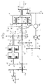
- Figure 1 schematically shows a CVT transmission of the present invention in a first condition (meshing of the first forward running mode);
- Figure 2 schematically shows the CVT transmission of the present invention in a second condition (meshing of the second forward running mode);
- Figure 3 schematically shows the CVT transmission of the present invention in a third condition (meshing of the third forward running mode);
- Figure 4 schematically shows the CVT transmission of the present invention in a fourth condition (meshing of the fourth forward running mode); and
- Figure 5 schematically shows a CVT transmission of the present invention in a fifth condition (meshing of the reverse running mode).
- In Figure 1, the
reference 10 globally designates a CVT transmission of the present invention in a first condition of engagement thereof, i.e. when the first forward running mode (I) is engaged (see below). - More specifically, as known in the art, the
transmission 10 comprises ahydrostatic unit 11, in turn comprising avariable displacement pump 12a operatively connected to a fixeddisplacement motor 12b. In known fashion, the output of thevariable displacement pump 12a can be adjusted by means of a swash plate (not shown) of which the position is controlled by electronic means better described below. - The
hydrostatic unit 11, in dependence of adjustment means better explained below, is operable to drive agear wheel 13 keyed onto a transmission shaft 14. Thegear wheel 13 meshes with afurther gear wheel 15 keyed onto ashaft 16 to which anothergear wheel 17 is fixedly attached. This arrangement of gears is operable to send the regulating motion generated by thehydrostatic unit 11 towards an epicyclic rotary mechanism globally designated by the number 18 (see below). - An
internal combustion engine 19 drives adrive shaft 20 mechanically connected directly, in traditional fashion, with a PTO of the tractor. Moreover, thedrive shaft 20 drives parts of the epicyclicrotary mechanism 18. More particularly, the epicyclicrotary mechanism 18 comprises, in known fashion, afirst sun gear 21 keyed directly onto thedrive shaft 20. Thefirst sun gear 21 meshes with a plurality of planet gears or satellites positioned, in conventional manner, around the first sun gear 21 (in Figure 1, only twoplanet gears 22 are shown). - The epicyclic
rotary mechanism 18 further comprises aspider 23 carrying theplanet gears 22 and extending into ahollow shaft 24. Aring wheel 25 is operatively connected with theaforesaid gear wheel 17 through anothergear wheel 26 whereby thehydrostatic unit 11 is mechanically connected with the epicyclicrotary mechanism 18. - It will be observed that the
first sun gear 21 meshes withgear wheels 27 of theplanet gears 22, whereas thegear wheels 28 of thesatellites 22 simultaneously mesh with thering 25 and with asecond sun gear 29. As shown in the accompanying figures, thesecond sun gear 29 is keyed onto atransmission shaft 30. - In summary, motion enters the epicyclic
rotary mechanism 18 from thefirst sun gear 21 by means of thedrive shaft 20, rotating with an angular speed imposed by theinternal combustion engine 19, and from thering wheel 25 rotated through the engagement of thegear wheel 26 with 17(motion imposed by the hydrostatic unit 11). - As mentioned above, modulating the angular velocity of the
gear wheel 17 by means of thehydrostatic unit 11, the output speed of the epicyclicrotary mechanism 18 can be modulated. - The two output elements from the
epicyclic rotary mechanism 18 are thespider 23, with therelated transmission shaft 24, and thesecond sun gear 29 integral with thedrive shaft 30. Incidentally, thehollow shaft 30 is inserted coaxially within theshaft 24, which is also hollow. In turn, thedrive shaft 20 is housed within theshaft 30, which, as stated, is also hollow. Thus, in other words, the threeshafts - As shown in the accompanying drawings, the
shaft 24 bears threeidle gear wheels shaft 24. The synchroniser S1 is positioned between thegear wheels gear wheel 31 or thegear wheel 32 to theshaft 24. In turn, the synchroniser S2 is operable, in selective fashion, to fixedly connect thegear wheel 33 to thetransmission shaft 24, in a manner that will become more readily apparent below. - The
gear wheel 31 permanently meshes with agear wheel 34 keyed onto atransmission shaft 35 mechanically connected with a first clutch A. Similarly, thegear wheel 32 permanently meshes with agear wheel 36 also keyed onto theshaft 35. Theshaft 35 extends parallel to theshafts - Incidentally, the
shafts drive shaft 20. However, it is necessary to specify that theshaft 24 in some conditions of travel reaches zero speed. - The clutch A is mechanically connected to a differential gear DIF by means of a
motion transferring unit 37. Theunit 37 comprises ashaft 38, integral with the output side of the clutch A, whereon agear wheel 39 is fixedly connected. Thegear wheel 39 meshes with agear wheel 40 fastened to ahollow shaft 41 traversed by thedrive shaft 20, which, as stated, sets the PTO in rotation. Theshaft 41 further comprises a fixedly connectedgear wheel 42 which meshes with agear wheel 43 integral with amechanical connection shaft 44 with apinion 45 of the differential gear DIF. The presence of themotion transfer unit 37 is not indispensable and the clutch A could be connected directly to the differential DIF. - The
gear wheel 33, which, as already mentioned, is normally idle on theshaft 24, meshes with anidle gear 46, which, in turn, also meshes with agear wheel 47 fixedly connected to ahollow transmission shaft 48 through which passes theaforesaid transmission shaft 35. As will be seen, theidle wheel 46 serves the purpose of inverting the sense of rotation of thegear wheel 47 to obtain the desired reverse running mode (see below). - A second clutch B, mechanically connected to the
transmission shaft 48, is operable to transmit motion to theunit 37, and hence, finally, to the differential gear DIF. The clutch B is positioned "upstream" of the clutch A and, as shown for example in Figure 2, the clutches A and B are constructed such that when the clutch B is closed, motion from the epicyclicrotary mechanism 18 is transmitted to an external housing portion of the clutch A. In as much as this external housing portion is connected toshaft 38, there is a continuity of the transmission towards the differential gear DIF. - Two
idle gear wheels transmission shaft 30. A third bi-directional synchroniser S3, integral with theshaft 30, is inserted inbetween thegear wheels gear wheels gear wheels connection shaft 48, in turn connected to the outer housing of the second clutch B. - Summarising, the
gear wheels shafts gearbox 53. - As shown in the accompanying drawings, to set the impeller (not shown) of the
pump 12a of thehydraulic unit 11 in rotation, atransmission unit 70 is employed comprising agear wheel 71 keyed onto thedrive shaft 20, and agear wheel 72 integral with ashaft 73 mechanically connected to thepump 12a. To transmit the motion from thegear wheel 71 to thegear wheel 72, atransmission device 74 is provided comprising, in turn, ashaft 75 having afirst gear wheel 76 meshing with thegear wheel 71 and asecond gear wheel 77 meshing with thegear wheel 72. - It is readily apparent for those skilled in the art that instead of the
device 74 and of the pair ofgear wheels drive shaft 20 and theshaft 73. - Figure 1 further shows a
manual control 99 actuated by an operator who, through a lever L, imparts commands to thetransmission 10 to determine the engaged gear of the motor vehicle. The lever L is connected to anelectronic unit 100, which manages the signals measured by a series of sensors Sn. In particular, Sn1 is the sensor that measures the angular speed of thetransmission shaft 20, whilst Sn2 measures the angular speed of thering wheel 25 of the epicyclicrotary mechanism 18. Sn3 controls the speed of rotation of thesecond sun gear 29, whilst Sn4, Sn5, and Sn6 are sensors that respectively control the position of the synchronisers S1, S2, S3. To move the synchronisers S1, S2, S3, respective actuators (not shown) are provided. - Two sensors Sn7 and Sn8 control the engagement, or disengagement, respectively, of the clutches A and B. The sensor Sn9 measures the angular speed of the
shaft 44, whilst the sensor Sn10 controls the operating conditions of the pump 12 of thehydraulic unit 11. Lastly, the sensor Sn11 detects the command imparted by the operator through the lever L. - As will become more readily apparent in the description of the operation of the
transmission 10 of the present invention, theunit 100 sets the general conditions of operation of thehydraulic unit 11, of the synchronisers S1, S2, S3 and of the clutches A and B in such a way as to have a condition of travel of the motor vehicle corresponding to the commands imparted by the operator by means of the lever L, obviously taking the values measures by the sensors Sn appropriately into account. - As shown in the accompanying drawings, the transmission of the motion through the
gear wheels gear wheels - By means of the transmission of the motion with the train of
gear wheels 33, 46 (idle wheel, for reversing the direction of rotation) and 47, the reverse running mode (R) is obtained. - With regard to the second forward running mode (II) and the fourth forward running mode (IV), they are obtained in the transmission by means of the coupling between the
gear wheels gear wheels - The operation of the
CVT transmission 10 of the present invention is the following. - Assuming that the tractor is in the condition of first forward running mode (I), as shown in Figure 1, the synchroniser S1 acts on the
gear wheel 31 to make it integral with theshaft 24. The mechanical power, generated by theinternal combustion engine 19, is sent to thegear wheel 34 through theepicyclic rotary mechanism 18, which sets thetransmission shaft 35 in rotation. The first clutch A is closed (whilst the second clutch B is open), so the mechanical power is transmitted through the clutch A to theshaft 38, to theunit 37 and hence to the differential gear DIF. - If the operator, through the lever L, sends a signal to the
electronic unit 100 to increase the speed of the vehicle to a value obtainable only in second running mode (II), the synchroniser S3 acts on thegear wheel 50 to make it integral with thetransmission shaft 30. This action sets thegear wheel 52 into rotation, and as it meshes with thegear wheel 50, also thetransmission shaft 48 starts to rotate. No power is transmitted to the differential gear DIF however because the related clutch B is still open. - The system knows that it must shift running modes (in the present situation from first to second) in the optimal conditions, so the
hydraulic unit 11, acting on thering wheel 25 of theepicyclic rotary mechanism 18, sets thetransmission shaft 24, and hence thegear wheel 31, into rotation, towards the maximum limit of the first forward running mode (I). It is readily apparent for those skilled in the art that the speed of rotation of theshafts epicyclic rotary mechanism 18 and the well known Willis formulas. - At this point, the
electronic unit 100 commands the closure of the second clutch B and the opening of the first clutch A. Therefore, mechanical power will be transmitted from theengine 19 to the differential gear DIF passing through theshaft 30, the pair ofgear wheels shaft 48, the closed clutch B (whilst the friction A, as stated, is opened by the system), theshaft 30 and theunit 37. The condition of the transmission in the second running mode is the one shown in Figure 2. It should be stressed that the opening and closing operations (or vice versa) of the clutch A and of the clutch B must be performed by the system in gradual and proportional fashion, in order to have the "smoothest" possible running mode shift. - The shift to the third forward running mode (III) is shown in Figure 3 and it takes place substantially in a comparable manner as described above for the shift from the first running mode (I) to the second running mode (II). In particular, to obtain the third forward running mode (III) (Figure 3), the synchroniser S1 disconnects from the gear wheel 31 (of the first running mode (I)) and acts on the
gear wheel 32 to make it integral with theshaft 24. The motion is therefore transmitted to thegear wheel 36, which, by means of the closed clutch A (the clutch B is open; see Figure 3) transmits power to the differential gear DIF; - The shift from the third forward running mode (III) to the fourth forward running mode (IV) is shown in Figure 4 and is completely similar to the running mode shifts described above. Clearly, every time the shift is made from a lower running mode to a higher running mode, the
unit 100 causes thehydraulic unit 11 to bring the speed of rotation of the output shaft towards a level equal with the highest speed obtainable by the lower running mode. Similarly, when the system has to shift from a higher running mode to a lower running mode, for example from the third forward running mode (III) to the second forward running mode (II), theunit 100 imparts such commands as to cause the output shaft to assume the lower speed before the running mode shift is actually achieved in the manners described above. - Similarly, to engage the reverse running mode (R), the system will disengage the synchronisers S1 and S3, idling the
gear wheels respective shafts gear wheel 33 to make it integral with thetransmission shaft 24. As such, the motion is transmitted to thegear wheels shaft 48 and to the closed clutch (B), as shown in Figure 5. The presence of theidle wheel 46 causes a rotation in the opposite direction of thepinion 45 of the differential gear DIF, thereby achieving the desired reverse running gear (R). It is clear that in this case the system will be able to shift running gears gradually to the first forward running mode (I) and to zero speed, then shift to reverse running mode (R), or alternatively, it will be able to shift directly from the first running mode (I) to the reverse running mode (R) through the direct actuation of the related clutches A, B. - In other words, in the
CVT transmission 10 of the present invention it is possible to pre-synchronise a running mode before actually shifting running modes. Moreover, the pre-selection logic of the plurality of synchronisers S1, S2, S3 and the modulated engagement/disengagement of the two friction clutches (A, B) allows to pass from one range to another also in conditions of imperfect rpm synchronism (as a result of the presence of the friction clutches), considerably simplifying the electronic control of the system. - The advantages of the present CVT transmission can be summarised as follows:
- Reversal of motion from the first forward running mode (I) to the reverse running mode (R) is achieved mechanically, by opening one clutch and closing the other (instead of in purely hydrostatic fashion), with a consequent simplification of the operation of the system; and
- Pre-synchronisation of the next running mode before actually making the shift, results in a smoother shifting process. Since it is possible to pre-synchronise the reverse running mode (R) at any time while travelling forward, a smooth running mode shift can be effected just by acting on the clutches A and B.
Claims (14)
- A CVT transmission (10) for a motor vehicle, in particular an agricultural tractor, comprising a hydraulic unit (11), an epicyclic rotary mechanism (18), a gearbox (53) and a differential gear (DIF), and
characterized in that said gearbox (53) comprises:a first shaft (24) and a second shaft (30) at the output of the epicyclic rotary mechanism (18) whereon are mounted idle, respectively, a first plurality of gear wheels (31, 32, 33) and a second plurality of gear wheels (49, 50);a plurality of synchronisers (S1, S2), able to render said first plurality of gear wheels (31, 32, 33) selectively integral with the respective first shaft (24);a synchroniser (S3), able to render said second plurality of gear wheels (49,50) selectively integral with the respective second shaft (30);a third plurality of gear wheels (34, 36), keyed onto a third shaft (35) and a fourth plurality of gear wheels (47, 51, 52) keyed onto a fourth shaft (48);a first clutch (A), mechanically connected with said third shaft (35) and a second clutch (B), mechanically connected with said fourth shaft (48); the arrangement being such that by the selective engagement of said synchronisers (S1, S2) and (S3) making said first plurality of gear wheels (31, 32, 33) and said second plurality of gear wheels (49, 50) selectively integral with, respectively, said first shaft (24) and said second shaft (30), and by the selective actuation of said first clutch (A) or said second clutch (B), all the running modes (I, II, III, IV, R) provided in said gearbox (53) are obtainable. - A CVT transmission according to claim 1, characterized in that, when a first gear wheel (31) of said first plurality of gear wheels is integral with the first shaft (24), motion is transmitted to the differential gear (DIF) through a first gear wheel (34) of said third plurality of gear wheels integral with the third shaft (35); the first clutch (A), mechanically connected to the third shaft (35), being closed to obtain the first forward running mode (I).
- A CVT transmission according to claim 1 or 2, characterized in that, when a first gear wheel (50) of said second plurality of gear wheels is integral with the second shaft (30), motion is transmitted to the differential gear (DIF) through a first gear wheel (52) of said fourth plurality of gear wheels integral with the fourth shaft (48); the second clutch (B), mechanically connected to the fourth shaft (48), being closed to obtain the second forward running mode (II).
- A CVT transmission according to any of the preceding claims, characterized in that, when a second gear wheel (32) of said first plurality of gear wheels is integral with the first shaft (24), motion is transmitted to the differential gear (DIF) through a second gear wheel (36) of said third plurality of gear wheels integral with the third shaft (35); the first clutch (A), mechanically connected to the third shaft (35), being closed to obtain the third forward running mode (III).
- A CVT transmission according to any of the preceding claims, characterized in that, when a second gear wheel (49) of said second plurality of gear wheels is integral with the second shaft (30), motion is transmitted to the differential gear (DIF) through a second gear wheel (51) of said fourth plurality of gear wheels integral with the fourth shaft (48); the second clutch (B), mechanically connected to the second shaft (48), being closed to obtain the fourth forward running mode (IV).
- A CVT transmission according to any of the preceding claims, characterized in that, when a third gear wheel (33) of said first plurality of gear wheels is integral with the first shaft (24), motion is transmitted to the differential gear (DIF) through an idle gear wheel (46) meshing with a third gear wheel (47) of said fourth plurality of gear wheels integral with the fourth shaft (48); the second clutch (B), mechanically connected to the fourth shaft (48), being closed to obtain the reverse running mode (R).
- A CVT transmission according to claims 2 or 6, characterized in that said first gear wheel (31) of the first forward running mode (I) and said third gear wheel (33) of the reverse running mode (R) are selectively connectable to said first shaft (24); said first shaft being integral with a spider member (23) of the epicyclic rotary mechanism (18).
- A CVT transmission according to claim 7, characterized in that said first gear wheel (31) of said first plurality of gear wheels, supported by said first shaft (24), meshes with said first gear wheel (34) of said third plurality of gear wheels integral with the third shaft (35); said third shaft (35) being mechanically connected to the first clutch (A); and in that said third gear wheel (33) of said first plurality of gear wheels, supported by the first shaft (24) meshes with said idle wheel (46); said idle wheel (46) in turn meshing with said third gear wheel (47) of said fourth plurality of gear wheels integral with said fourth shaft (48) mechanically connected with the second clutch (B).
- A CVT transmission according to claim 8, characterized in that a switch between the first forward running mode (I) and the reverse running mode (R) is effected by opening one of said first and second clutches (A, B) and closing the other.
- A CVT transmission according to any of the preceding claims, characterized in that the first clutch (A) and the second clutch (B) are arranged in series and are mechanically connected to each other and to the differential gear (DIV) in such a way that, when the second clutch (B) is closed and the first clutch (A) is opened, at least one part of the first clutch (A) is set in rotation to transmit motion to the differential gear (DIF) through the closed second clutch (B).
- A CVT transmission according to any of the preceding claims, characterized in that the first and second shafts (24, 30) have the same axis of longitudinal symmetry; the second shaft (30) being positioned inside the first, hollow shaft (24).
- A CVT transmission according to claim 11, characterized in that a fifth shaft (20), coupled to the output of an internal combustion engine (19) of the vehicle, traverses the first, hollow shaft (24) to actuate a remote power take-off (PTO) mechanism.
- A CVT transmission according to any of the preceding claims, characterized in that the speed setting of the motor vehicle is regulated by an electronic unit (100) which receives the signals selected by an operator through control means (L) as a function of parameters measured by means of a variety of sensors (Sn1-Sn11).
- A CVT transmission according to any of the preceding claims, characterized in that said gearbox (53) is connected to the output side of said epicyclic rotary mechanism (18); said first and second clutches (A, B) being located at the output side of said gearbox (53) inbetween said gearbox (53) and said differential gear (DIF).
Applications Claiming Priority (2)
| Application Number | Priority Date | Filing Date | Title |
|---|---|---|---|
| ITBO20030748 | 2003-12-12 | ||
| IT000748A ITBO20030748A1 (en) | 2003-12-12 | 2003-12-12 | CVT TRANSMISSION FOR MOTOR VEHICLES, IN PARTICULAR FOR TRACTORS |
Publications (3)
| Publication Number | Publication Date |
|---|---|
| EP1541898A2 true EP1541898A2 (en) | 2005-06-15 |
| EP1541898A3 EP1541898A3 (en) | 2006-02-08 |
| EP1541898B1 EP1541898B1 (en) | 2010-03-03 |
Family
ID=34509420
Family Applications (1)
| Application Number | Title | Priority Date | Filing Date |
|---|---|---|---|
| EP04106428A Expired - Lifetime EP1541898B1 (en) | 2003-12-12 | 2004-12-09 | CVT transmission for motor vehicles, in particular for tractors |
Country Status (4)
| Country | Link |
|---|---|
| EP (1) | EP1541898B1 (en) |
| AT (1) | ATE459823T1 (en) |
| DE (1) | DE602004025784D1 (en) |
| IT (1) | ITBO20030748A1 (en) |
Cited By (29)
| Publication number | Priority date | Publication date | Assignee | Title |
|---|---|---|---|---|
| WO2006132954A1 (en) * | 2005-06-03 | 2006-12-14 | Caterpillar Inc. | Multi-range hydromechanical transmission and method of operation |
| WO2006132986A3 (en) * | 2005-06-03 | 2007-01-18 | Caterpillar Inc | Hydromechanical transmission |
| DE102008040444A1 (en) * | 2008-07-16 | 2010-01-21 | Zf Friedrichshafen Ag | Power split transmission for use in e.g. tractor, has internal gear connected with driven shaft by control unit, center gear connected with driven shaft by another control unit, and shaft in effective-connection with center gear |
| EP2166256A1 (en) | 2008-09-19 | 2010-03-24 | CNH Italia S.p.A. | An agricultural vehicle with a continuously variable transmission |
| EP1961994A3 (en) * | 2007-01-23 | 2010-08-25 | Kanzaki Kokyukoki Mfg. Co., Ltd. | Working-vehicle transmission system |
| EP2253867A1 (en) * | 2009-05-19 | 2010-11-24 | Heinz Aitzetmüller | Power split drive |
| EP1930627A4 (en) * | 2005-09-30 | 2011-07-06 | Kubota Kk | TRANSMISSION DEVICE FOR CHANGING SPEED |
| EP2045486A4 (en) * | 2006-07-06 | 2011-11-30 | Kubota Kk | DEVICE FOR DISPLACING AND TRANSMITTING POWER |
| DE102010003943A1 (en) | 2010-04-14 | 2011-12-15 | Zf Friedrichshafen Ag | Gear box device for drive train of tractor, has clutch system provided in gearbox region for switch-on and off gearbox power paths, where parts of clutch system and switching elements represent paths on axle stitch of output shaft |
| DE102010029865A1 (en) | 2010-06-09 | 2011-12-15 | Zf Friedrichshafen Ag | Continuously variable power-split transmission for tractor, has wheel connected with shaft, where other wheels are connected with switching element portion for representation of fields over switch element and frictional switching element |
| WO2012071362A1 (en) * | 2010-11-24 | 2012-05-31 | Caterpillar Inc. | Method of synchronizing in split torque continuously variable dual clutch transmission |
| US8262530B2 (en) | 2007-10-02 | 2012-09-11 | Zf Friedrichshafen Ag | Power-branched transmission |
| US8262525B2 (en) | 2007-10-02 | 2012-09-11 | Zf Friedrichshafen Ag | Hydrostatic-mechanical power split transmission |
| US8287414B2 (en) | 2007-10-02 | 2012-10-16 | Zf Friedrichshafen Ag | Transmission device having a variator |
| US8323138B2 (en) | 2007-10-02 | 2012-12-04 | Zf Friedrichshafen Ag | Power split transmission |
| US8328676B2 (en) | 2007-10-02 | 2012-12-11 | Zf Friedrichshafen Ag | Power split transmission |
| WO2012171813A1 (en) | 2011-06-14 | 2012-12-20 | Valtra Oy Ab | Vehicle transmission and corresponding control method |
| WO2012171815A1 (en) | 2011-06-14 | 2012-12-20 | Valtra Oy Ab | Continuously variable power-split vehicle transmission |
| US8393988B2 (en) | 2007-10-02 | 2013-03-12 | Zf Friedrichshafen Ag | Transmission device for a vehicle |
| US8414439B2 (en) | 2007-10-02 | 2013-04-09 | Zf Friedrichshafen Ag | Transmission device for a vehicle, having a variator |
| US8424633B2 (en) | 2007-10-02 | 2013-04-23 | Zf Friedrichshafen Ag | Variable transmission device for a vehicle |
| US8752374B2 (en) | 2007-10-02 | 2014-06-17 | Zf Friedrichshafen Ag | Device for adjusting the stroke volume of hydraulic piston machines |
| US8756931B2 (en) | 2007-10-02 | 2014-06-24 | Zf Friedrichshafen Ag | Device for adjusting the stroke volume of hydraulic piston machines |
| CN108397534A (en) * | 2018-04-10 | 2018-08-14 | 北京理工大学 | Loading machine three-stage Hydromechanical Stepless Transmission device |
| CN111946799A (en) * | 2020-08-14 | 2020-11-17 | 重庆大江智防特种装备有限公司 | Automobile power transmission case |
| CN113090731A (en) * | 2021-03-23 | 2021-07-09 | 北京理工大学 | Multi-power flow composite stepless transmission device |
| CN114151527A (en) * | 2021-12-09 | 2022-03-08 | 浙江盘毂动力科技有限公司 | Zero-differential-speed stepless-steering hydraulic mechanical combined type comprehensive transmission device and vehicle |
| IT202300004428A1 (en) * | 2023-03-09 | 2024-09-09 | Cnh Ind Italia Spa | METHOD AND APPARATUS FOR CHECKING THE CORRECT ASSEMBLY OF A CONTINUOUSLY VARIABLE TRANSMISSION OF A WORK VEHICLE |
| IT202300019866A1 (en) | 2023-09-26 | 2025-03-26 | Cnh Ind Italia Spa | METHOD OF CONTROLLING A TRANSMISSION OF AN AGRICULTURAL VEHICLE AND AGRICULTURAL VEHICLE IMPLEMENTING THE METHOD |
Family Cites Families (3)
| Publication number | Priority date | Publication date | Assignee | Title |
|---|---|---|---|---|
| DE4021643A1 (en) * | 1990-07-06 | 1992-01-16 | Claas Ohg | HYDROSTATIC-POWER-BRANCHED MULTI-SPEED POWERTRAIN GEARBOX |
| GB9213703D0 (en) * | 1992-06-27 | 1992-08-12 | Massey Ferguson Sa | Transmissions |
| US6565471B2 (en) * | 2000-12-19 | 2003-05-20 | Case Corporation | Continuously variable hydro-mechanical transmission |
-
2003
- 2003-12-12 IT IT000748A patent/ITBO20030748A1/en unknown
-
2004
- 2004-12-09 EP EP04106428A patent/EP1541898B1/en not_active Expired - Lifetime
- 2004-12-09 DE DE602004025784T patent/DE602004025784D1/en not_active Expired - Lifetime
- 2004-12-09 AT AT04106428T patent/ATE459823T1/en not_active IP Right Cessation
Non-Patent Citations (1)
| Title |
|---|
| None |
Cited By (37)
| Publication number | Priority date | Publication date | Assignee | Title |
|---|---|---|---|---|
| WO2006132986A3 (en) * | 2005-06-03 | 2007-01-18 | Caterpillar Inc | Hydromechanical transmission |
| US7530913B2 (en) | 2005-06-03 | 2009-05-12 | Caterpillar Inc. | Multi-range hydromechanical transmission |
| US7530914B2 (en) | 2005-06-03 | 2009-05-12 | Caterpillar Inc. | Hydromechanical transmission |
| WO2006132954A1 (en) * | 2005-06-03 | 2006-12-14 | Caterpillar Inc. | Multi-range hydromechanical transmission and method of operation |
| EP1930627A4 (en) * | 2005-09-30 | 2011-07-06 | Kubota Kk | TRANSMISSION DEVICE FOR CHANGING SPEED |
| EP2848841A1 (en) * | 2006-07-06 | 2015-03-18 | Kubota Corporation | Shifting and power transmission device with power take-off |
| EP2045486A4 (en) * | 2006-07-06 | 2011-11-30 | Kubota Kk | DEVICE FOR DISPLACING AND TRANSMITTING POWER |
| EP1961994A3 (en) * | 2007-01-23 | 2010-08-25 | Kanzaki Kokyukoki Mfg. Co., Ltd. | Working-vehicle transmission system |
| US8393988B2 (en) | 2007-10-02 | 2013-03-12 | Zf Friedrichshafen Ag | Transmission device for a vehicle |
| US8414439B2 (en) | 2007-10-02 | 2013-04-09 | Zf Friedrichshafen Ag | Transmission device for a vehicle, having a variator |
| US8756931B2 (en) | 2007-10-02 | 2014-06-24 | Zf Friedrichshafen Ag | Device for adjusting the stroke volume of hydraulic piston machines |
| US8752374B2 (en) | 2007-10-02 | 2014-06-17 | Zf Friedrichshafen Ag | Device for adjusting the stroke volume of hydraulic piston machines |
| US8424633B2 (en) | 2007-10-02 | 2013-04-23 | Zf Friedrichshafen Ag | Variable transmission device for a vehicle |
| US8262530B2 (en) | 2007-10-02 | 2012-09-11 | Zf Friedrichshafen Ag | Power-branched transmission |
| US8262525B2 (en) | 2007-10-02 | 2012-09-11 | Zf Friedrichshafen Ag | Hydrostatic-mechanical power split transmission |
| US8287414B2 (en) | 2007-10-02 | 2012-10-16 | Zf Friedrichshafen Ag | Transmission device having a variator |
| US8323138B2 (en) | 2007-10-02 | 2012-12-04 | Zf Friedrichshafen Ag | Power split transmission |
| US8328676B2 (en) | 2007-10-02 | 2012-12-11 | Zf Friedrichshafen Ag | Power split transmission |
| DE102008040444A1 (en) * | 2008-07-16 | 2010-01-21 | Zf Friedrichshafen Ag | Power split transmission for use in e.g. tractor, has internal gear connected with driven shaft by control unit, center gear connected with driven shaft by another control unit, and shaft in effective-connection with center gear |
| EP2166256A1 (en) | 2008-09-19 | 2010-03-24 | CNH Italia S.p.A. | An agricultural vehicle with a continuously variable transmission |
| US8639419B2 (en) | 2008-09-19 | 2014-01-28 | Cnh America Llc | Agricultural vehicle with a continuously variable transmission |
| EP2253867A1 (en) * | 2009-05-19 | 2010-11-24 | Heinz Aitzetmüller | Power split drive |
| DE102010003943A1 (en) | 2010-04-14 | 2011-12-15 | Zf Friedrichshafen Ag | Gear box device for drive train of tractor, has clutch system provided in gearbox region for switch-on and off gearbox power paths, where parts of clutch system and switching elements represent paths on axle stitch of output shaft |
| DE102010029865A1 (en) | 2010-06-09 | 2011-12-15 | Zf Friedrichshafen Ag | Continuously variable power-split transmission for tractor, has wheel connected with shaft, where other wheels are connected with switching element portion for representation of fields over switch element and frictional switching element |
| DE102010029865B4 (en) | 2010-06-09 | 2023-01-12 | Zf Friedrichshafen Ag | Infinitely variable power-split transmission |
| US8523724B2 (en) | 2010-11-24 | 2013-09-03 | Caterpillar Inc. | Method of synchronizing in split torque continuously variable dual clutch transmission |
| WO2012071362A1 (en) * | 2010-11-24 | 2012-05-31 | Caterpillar Inc. | Method of synchronizing in split torque continuously variable dual clutch transmission |
| WO2012171815A1 (en) | 2011-06-14 | 2012-12-20 | Valtra Oy Ab | Continuously variable power-split vehicle transmission |
| WO2012171813A1 (en) | 2011-06-14 | 2012-12-20 | Valtra Oy Ab | Vehicle transmission and corresponding control method |
| CN108397534A (en) * | 2018-04-10 | 2018-08-14 | 北京理工大学 | Loading machine three-stage Hydromechanical Stepless Transmission device |
| CN111946799A (en) * | 2020-08-14 | 2020-11-17 | 重庆大江智防特种装备有限公司 | Automobile power transmission case |
| CN113090731A (en) * | 2021-03-23 | 2021-07-09 | 北京理工大学 | Multi-power flow composite stepless transmission device |
| CN114151527A (en) * | 2021-12-09 | 2022-03-08 | 浙江盘毂动力科技有限公司 | Zero-differential-speed stepless-steering hydraulic mechanical combined type comprehensive transmission device and vehicle |
| CN114151527B (en) * | 2021-12-09 | 2023-10-13 | 浙江盘毂动力科技有限公司 | Hydro-mechanical compound integrated transmission device and vehicle with zero differential speed and stepless steering |
| IT202300004428A1 (en) * | 2023-03-09 | 2024-09-09 | Cnh Ind Italia Spa | METHOD AND APPARATUS FOR CHECKING THE CORRECT ASSEMBLY OF A CONTINUOUSLY VARIABLE TRANSMISSION OF A WORK VEHICLE |
| IT202300019866A1 (en) | 2023-09-26 | 2025-03-26 | Cnh Ind Italia Spa | METHOD OF CONTROLLING A TRANSMISSION OF AN AGRICULTURAL VEHICLE AND AGRICULTURAL VEHICLE IMPLEMENTING THE METHOD |
| EP4530502A1 (en) | 2023-09-26 | 2025-04-02 | CNH Industrial Italia S.p.A. | Method for controlling a transmission of an agricultural vehicle and agricultural vehicle implementing the method |
Also Published As
| Publication number | Publication date |
|---|---|
| EP1541898A3 (en) | 2006-02-08 |
| EP1541898B1 (en) | 2010-03-03 |
| ITBO20030748A1 (en) | 2005-06-13 |
| DE602004025784D1 (en) | 2010-04-15 |
| ATE459823T1 (en) | 2010-03-15 |
Similar Documents
| Publication | Publication Date | Title |
|---|---|---|
| EP1541898B1 (en) | CVT transmission for motor vehicles, in particular for tractors | |
| JP4686734B2 (en) | Output-branched transmission having a plurality of speed ranges having a continuously variable speed ratio | |
| EP0756107B1 (en) | A twin-clutch-type transmission | |
| US4392394A (en) | Engine-gear arrangement for vehicles, in particular passenger cars | |
| EP0071801B1 (en) | A variable v-belt type continuously variable transmission for vehicles | |
| US5052986A (en) | Continuous-acting hydrostatic-mechanical power-shift transmission with toothed clutches | |
| CA1037738A (en) | Hydromechanical transmission with overspeed limited variable drive | |
| CA2861308C (en) | Multi-speed automatic transmission with fast reverse | |
| WO2016069337A1 (en) | Multi-speed transmission | |
| EP1660789B1 (en) | Hydromechanical transmission for agricultural tractors | |
| GB2100812A (en) | Motor vehicle transmission mechanism | |
| EP0081260B1 (en) | Transmission, in particular for a vehicle, provided with a hydrodynamic torque converter | |
| JPH0338460B2 (en) | ||
| US20040261555A1 (en) | Layshaft automatic transmission having power-on shifting | |
| WO2024169151A1 (en) | Transmission system and transmission method | |
| CN113370777A (en) | Hybrid power train of vehicle | |
| CN115056648A (en) | Transmission system and vehicle with same | |
| US20080163710A1 (en) | Double Clutch Gearbox, In Particular For a Motor Vehicle | |
| EP1342937B1 (en) | Infinitely variable transmission. | |
| JPS5948895B2 (en) | transmission | |
| US20200378475A1 (en) | Transmission multi-speed adder | |
| CN219242581U (en) | transmission system | |
| EP0632217B1 (en) | Power transmission and control | |
| US10948052B2 (en) | Transmission range adder | |
| JP3630131B2 (en) | Automatic transmission input rotation transmission mechanism |
Legal Events
| Date | Code | Title | Description |
|---|---|---|---|
| PUAI | Public reference made under article 153(3) epc to a published international application that has entered the european phase |
Free format text: ORIGINAL CODE: 0009012 |
|
| AK | Designated contracting states |
Kind code of ref document: A2 Designated state(s): AT BE BG CH CY CZ DE DK EE ES FI FR GB GR HU IE IS IT LI LT LU MC NL PL PT RO SE SI SK TR |
|
| AX | Request for extension of the european patent |
Extension state: AL BA HR LV MK YU |
|
| PUAL | Search report despatched |
Free format text: ORIGINAL CODE: 0009013 |
|
| AK | Designated contracting states |
Kind code of ref document: A3 Designated state(s): AT BE BG CH CY CZ DE DK EE ES FI FR GB GR HU IE IS IT LI LT LU MC NL PL PT RO SE SI SK TR |
|
| AX | Request for extension of the european patent |
Extension state: AL BA HR LV MK YU |
|
| 17P | Request for examination filed |
Effective date: 20060704 |
|
| AKX | Designation fees paid |
Designated state(s): AT BE BG CH CY CZ DE DK EE ES FI FR GB GR HU IE IS IT LI LT LU MC NL PL PT RO SE SI SK TR |
|
| 17Q | First examination report despatched |
Effective date: 20061116 |
|
| GRAP | Despatch of communication of intention to grant a patent |
Free format text: ORIGINAL CODE: EPIDOSNIGR1 |
|
| GRAS | Grant fee paid |
Free format text: ORIGINAL CODE: EPIDOSNIGR3 |
|
| GRAA | (expected) grant |
Free format text: ORIGINAL CODE: 0009210 |
|
| AK | Designated contracting states |
Kind code of ref document: B1 Designated state(s): AT BE BG CH CY CZ DE DK EE ES FI FR GB GR HU IE IS IT LI LT LU MC NL PL PT RO SE SI SK TR |
|
| REG | Reference to a national code |
Ref country code: GB Ref legal event code: FG4D |
|
| REG | Reference to a national code |
Ref country code: CH Ref legal event code: EP |
|
| REG | Reference to a national code |
Ref country code: IE Ref legal event code: FG4D |
|
| REF | Corresponds to: |
Ref document number: 602004025784 Country of ref document: DE Date of ref document: 20100415 Kind code of ref document: P |
|
| REG | Reference to a national code |
Ref country code: NL Ref legal event code: VDEP Effective date: 20100303 |
|
| PG25 | Lapsed in a contracting state [announced via postgrant information from national office to epo] |
Ref country code: LT Free format text: LAPSE BECAUSE OF FAILURE TO SUBMIT A TRANSLATION OF THE DESCRIPTION OR TO PAY THE FEE WITHIN THE PRESCRIBED TIME-LIMIT Effective date: 20100303 |
|
| LTIE | Lt: invalidation of european patent or patent extension |
Effective date: 20100303 |
|
| PG25 | Lapsed in a contracting state [announced via postgrant information from national office to epo] |
Ref country code: AT Free format text: LAPSE BECAUSE OF FAILURE TO SUBMIT A TRANSLATION OF THE DESCRIPTION OR TO PAY THE FEE WITHIN THE PRESCRIBED TIME-LIMIT Effective date: 20100303 Ref country code: SI Free format text: LAPSE BECAUSE OF FAILURE TO SUBMIT A TRANSLATION OF THE DESCRIPTION OR TO PAY THE FEE WITHIN THE PRESCRIBED TIME-LIMIT Effective date: 20100303 Ref country code: PL Free format text: LAPSE BECAUSE OF FAILURE TO SUBMIT A TRANSLATION OF THE DESCRIPTION OR TO PAY THE FEE WITHIN THE PRESCRIBED TIME-LIMIT Effective date: 20100303 Ref country code: FI Free format text: LAPSE BECAUSE OF FAILURE TO SUBMIT A TRANSLATION OF THE DESCRIPTION OR TO PAY THE FEE WITHIN THE PRESCRIBED TIME-LIMIT Effective date: 20100303 |
|
| PG25 | Lapsed in a contracting state [announced via postgrant information from national office to epo] |
Ref country code: CY Free format text: LAPSE BECAUSE OF FAILURE TO SUBMIT A TRANSLATION OF THE DESCRIPTION OR TO PAY THE FEE WITHIN THE PRESCRIBED TIME-LIMIT Effective date: 20100303 Ref country code: SE Free format text: LAPSE BECAUSE OF FAILURE TO SUBMIT A TRANSLATION OF THE DESCRIPTION OR TO PAY THE FEE WITHIN THE PRESCRIBED TIME-LIMIT Effective date: 20100303 Ref country code: RO Free format text: LAPSE BECAUSE OF FAILURE TO SUBMIT A TRANSLATION OF THE DESCRIPTION OR TO PAY THE FEE WITHIN THE PRESCRIBED TIME-LIMIT Effective date: 20100303 Ref country code: NL Free format text: LAPSE BECAUSE OF FAILURE TO SUBMIT A TRANSLATION OF THE DESCRIPTION OR TO PAY THE FEE WITHIN THE PRESCRIBED TIME-LIMIT Effective date: 20100303 Ref country code: GR Free format text: LAPSE BECAUSE OF FAILURE TO SUBMIT A TRANSLATION OF THE DESCRIPTION OR TO PAY THE FEE WITHIN THE PRESCRIBED TIME-LIMIT Effective date: 20100604 Ref country code: ES Free format text: LAPSE BECAUSE OF FAILURE TO SUBMIT A TRANSLATION OF THE DESCRIPTION OR TO PAY THE FEE WITHIN THE PRESCRIBED TIME-LIMIT Effective date: 20100614 Ref country code: EE Free format text: LAPSE BECAUSE OF FAILURE TO SUBMIT A TRANSLATION OF THE DESCRIPTION OR TO PAY THE FEE WITHIN THE PRESCRIBED TIME-LIMIT Effective date: 20100303 Ref country code: BE Free format text: LAPSE BECAUSE OF FAILURE TO SUBMIT A TRANSLATION OF THE DESCRIPTION OR TO PAY THE FEE WITHIN THE PRESCRIBED TIME-LIMIT Effective date: 20100303 |
|
| PG25 | Lapsed in a contracting state [announced via postgrant information from national office to epo] |
Ref country code: IS Free format text: LAPSE BECAUSE OF FAILURE TO SUBMIT A TRANSLATION OF THE DESCRIPTION OR TO PAY THE FEE WITHIN THE PRESCRIBED TIME-LIMIT Effective date: 20100703 Ref country code: BG Free format text: LAPSE BECAUSE OF FAILURE TO SUBMIT A TRANSLATION OF THE DESCRIPTION OR TO PAY THE FEE WITHIN THE PRESCRIBED TIME-LIMIT Effective date: 20100603 Ref country code: CZ Free format text: LAPSE BECAUSE OF FAILURE TO SUBMIT A TRANSLATION OF THE DESCRIPTION OR TO PAY THE FEE WITHIN THE PRESCRIBED TIME-LIMIT Effective date: 20100303 Ref country code: SK Free format text: LAPSE BECAUSE OF FAILURE TO SUBMIT A TRANSLATION OF THE DESCRIPTION OR TO PAY THE FEE WITHIN THE PRESCRIBED TIME-LIMIT Effective date: 20100303 |
|
| PLBE | No opposition filed within time limit |
Free format text: ORIGINAL CODE: 0009261 |
|
| STAA | Information on the status of an ep patent application or granted ep patent |
Free format text: STATUS: NO OPPOSITION FILED WITHIN TIME LIMIT |
|
| PG25 | Lapsed in a contracting state [announced via postgrant information from national office to epo] |
Ref country code: PT Free format text: LAPSE BECAUSE OF FAILURE TO SUBMIT A TRANSLATION OF THE DESCRIPTION OR TO PAY THE FEE WITHIN THE PRESCRIBED TIME-LIMIT Effective date: 20100705 Ref country code: DK Free format text: LAPSE BECAUSE OF FAILURE TO SUBMIT A TRANSLATION OF THE DESCRIPTION OR TO PAY THE FEE WITHIN THE PRESCRIBED TIME-LIMIT Effective date: 20100303 |
|
| 26N | No opposition filed |
Effective date: 20101206 |
|
| PG25 | Lapsed in a contracting state [announced via postgrant information from national office to epo] |
Ref country code: MC Free format text: LAPSE BECAUSE OF NON-PAYMENT OF DUE FEES Effective date: 20101231 |
|
| REG | Reference to a national code |
Ref country code: CH Ref legal event code: PL |
|
| PG25 | Lapsed in a contracting state [announced via postgrant information from national office to epo] |
Ref country code: IE Free format text: LAPSE BECAUSE OF NON-PAYMENT OF DUE FEES Effective date: 20101209 Ref country code: LI Free format text: LAPSE BECAUSE OF NON-PAYMENT OF DUE FEES Effective date: 20101231 Ref country code: CH Free format text: LAPSE BECAUSE OF NON-PAYMENT OF DUE FEES Effective date: 20101231 |
|
| PG25 | Lapsed in a contracting state [announced via postgrant information from national office to epo] |
Ref country code: LU Free format text: LAPSE BECAUSE OF NON-PAYMENT OF DUE FEES Effective date: 20101209 Ref country code: HU Free format text: LAPSE BECAUSE OF FAILURE TO SUBMIT A TRANSLATION OF THE DESCRIPTION OR TO PAY THE FEE WITHIN THE PRESCRIBED TIME-LIMIT Effective date: 20100904 |
|
| PG25 | Lapsed in a contracting state [announced via postgrant information from national office to epo] |
Ref country code: TR Free format text: LAPSE BECAUSE OF FAILURE TO SUBMIT A TRANSLATION OF THE DESCRIPTION OR TO PAY THE FEE WITHIN THE PRESCRIBED TIME-LIMIT Effective date: 20100303 |
|
| REG | Reference to a national code |
Ref country code: DE Ref legal event code: R082 Ref document number: 602004025784 Country of ref document: DE Representative=s name: PATENTANWAELTE WALLACH, KOCH & PARTNER, DE |
|
| REG | Reference to a national code |
Ref country code: DE Ref legal event code: R082 Ref document number: 602004025784 Country of ref document: DE Representative=s name: PATENTANWAELTE WALLACH, KOCH & PARTNER, DE Effective date: 20140623 Ref country code: DE Ref legal event code: R081 Ref document number: 602004025784 Country of ref document: DE Owner name: CNH INDUSTRIAL ITALIA S.P.A., IT Free format text: FORMER OWNER: CNH ITALIA S.P.A., MODENA, IT Effective date: 20140623 Ref country code: DE Ref legal event code: R082 Ref document number: 602004025784 Country of ref document: DE Representative=s name: PATENTANWAELTE WALLACH, KOCH, DR. HAIBACH, FEL, DE Effective date: 20140623 |
|
| REG | Reference to a national code |
Ref country code: FR Ref legal event code: CD Owner name: CNH INDUSTRIAL ITALIA S.P.A. Effective date: 20150313 |
|
| REG | Reference to a national code |
Ref country code: FR Ref legal event code: PLFP Year of fee payment: 12 |
|
| REG | Reference to a national code |
Ref country code: FR Ref legal event code: PLFP Year of fee payment: 13 |
|
| REG | Reference to a national code |
Ref country code: FR Ref legal event code: PLFP Year of fee payment: 14 |
|
| REG | Reference to a national code |
Ref country code: FR Ref legal event code: PLFP Year of fee payment: 15 |
|
| PGFP | Annual fee paid to national office [announced via postgrant information from national office to epo] |
Ref country code: FR Payment date: 20191220 Year of fee payment: 16 |
|
| PGFP | Annual fee paid to national office [announced via postgrant information from national office to epo] |
Ref country code: GB Payment date: 20191220 Year of fee payment: 16 |
|
| REG | Reference to a national code |
Ref country code: DE Ref legal event code: R082 Ref document number: 602004025784 Country of ref document: DE Representative=s name: MEISSNER BOLTE PATENTANWAELTE RECHTSANWAELTE P, DE |
|
| REG | Reference to a national code |
Ref country code: DE Ref legal event code: R084 Ref document number: 602004025784 Country of ref document: DE |
|
| PGFP | Annual fee paid to national office [announced via postgrant information from national office to epo] |
Ref country code: IT Payment date: 20201202 Year of fee payment: 17 |
|
| PGFP | Annual fee paid to national office [announced via postgrant information from national office to epo] |
Ref country code: DE Payment date: 20201224 Year of fee payment: 17 |
|
| GBPC | Gb: european patent ceased through non-payment of renewal fee |
Effective date: 20201209 |
|
| PG25 | Lapsed in a contracting state [announced via postgrant information from national office to epo] |
Ref country code: FR Free format text: LAPSE BECAUSE OF NON-PAYMENT OF DUE FEES Effective date: 20201231 |
|
| PG25 | Lapsed in a contracting state [announced via postgrant information from national office to epo] |
Ref country code: GB Free format text: LAPSE BECAUSE OF NON-PAYMENT OF DUE FEES Effective date: 20201209 |
|
| REG | Reference to a national code |
Ref country code: DE Ref legal event code: R119 Ref document number: 602004025784 Country of ref document: DE |
|
| PG25 | Lapsed in a contracting state [announced via postgrant information from national office to epo] |
Ref country code: DE Free format text: LAPSE BECAUSE OF NON-PAYMENT OF DUE FEES Effective date: 20220701 |
|
| PG25 | Lapsed in a contracting state [announced via postgrant information from national office to epo] |
Ref country code: IT Free format text: LAPSE BECAUSE OF NON-PAYMENT OF DUE FEES Effective date: 20211209 |