EP1541889A1 - Torque limiting assembly - Google Patents
Torque limiting assembly Download PDFInfo
- Publication number
- EP1541889A1 EP1541889A1 EP04078259A EP04078259A EP1541889A1 EP 1541889 A1 EP1541889 A1 EP 1541889A1 EP 04078259 A EP04078259 A EP 04078259A EP 04078259 A EP04078259 A EP 04078259A EP 1541889 A1 EP1541889 A1 EP 1541889A1
- Authority
- EP
- European Patent Office
- Prior art keywords
- drive member
- driven member
- torque limiting
- limiting assembly
- distal ends
- Prior art date
- Legal status (The legal status is an assumption and is not a legal conclusion. Google has not performed a legal analysis and makes no representation as to the accuracy of the status listed.)
- Withdrawn
Links
- 230000005540 biological transmission Effects 0.000 claims description 8
- 230000007246 mechanism Effects 0.000 claims description 7
- 230000000295 complement effect Effects 0.000 claims description 3
- 230000007257 malfunction Effects 0.000 description 1
- 230000004048 modification Effects 0.000 description 1
- 238000012986 modification Methods 0.000 description 1
Images


Classifications
-
- F—MECHANICAL ENGINEERING; LIGHTING; HEATING; WEAPONS; BLASTING
- F16—ENGINEERING ELEMENTS AND UNITS; GENERAL MEASURES FOR PRODUCING AND MAINTAINING EFFECTIVE FUNCTIONING OF MACHINES OR INSTALLATIONS; THERMAL INSULATION IN GENERAL
- F16D—COUPLINGS FOR TRANSMITTING ROTATION; CLUTCHES; BRAKES
- F16D43/00—Automatic clutches
- F16D43/02—Automatic clutches actuated entirely mechanically
- F16D43/20—Automatic clutches actuated entirely mechanically controlled by torque, e.g. overload-release clutches, slip-clutches with means by which torque varies the clutching pressure
- F16D43/202—Automatic clutches actuated entirely mechanically controlled by torque, e.g. overload-release clutches, slip-clutches with means by which torque varies the clutching pressure of the ratchet type
- F16D43/2028—Automatic clutches actuated entirely mechanically controlled by torque, e.g. overload-release clutches, slip-clutches with means by which torque varies the clutching pressure of the ratchet type with at least one part moving radially between engagement and disengagement
-
- F—MECHANICAL ENGINEERING; LIGHTING; HEATING; WEAPONS; BLASTING
- F16—ENGINEERING ELEMENTS AND UNITS; GENERAL MEASURES FOR PRODUCING AND MAINTAINING EFFECTIVE FUNCTIONING OF MACHINES OR INSTALLATIONS; THERMAL INSULATION IN GENERAL
- F16D—COUPLINGS FOR TRANSMITTING ROTATION; CLUTCHES; BRAKES
- F16D7/00—Slip couplings, e.g. slipping on overload, for absorbing shock
- F16D7/04—Slip couplings, e.g. slipping on overload, for absorbing shock of the ratchet type
- F16D7/048—Slip couplings, e.g. slipping on overload, for absorbing shock of the ratchet type with parts moving radially between engagement and disengagement
-
- Y—GENERAL TAGGING OF NEW TECHNOLOGICAL DEVELOPMENTS; GENERAL TAGGING OF CROSS-SECTIONAL TECHNOLOGIES SPANNING OVER SEVERAL SECTIONS OF THE IPC; TECHNICAL SUBJECTS COVERED BY FORMER USPC CROSS-REFERENCE ART COLLECTIONS [XRACs] AND DIGESTS
- Y10—TECHNICAL SUBJECTS COVERED BY FORMER USPC
- Y10S—TECHNICAL SUBJECTS COVERED BY FORMER USPC CROSS-REFERENCE ART COLLECTIONS [XRACs] AND DIGESTS
- Y10S474/00—Endless belt power transmission systems or components
- Y10S474/902—Particular connection between rim and hub
Definitions
- the subject invention relates to a transmission and torque limiting assembly intended for use in transmitting rotation from a drive to a compressor.
- Various torque limiting devices exist in the art that are used in compressors to decouple compressor shafts from driven members such as gears or pulleys. Although they may be used with almost any type of compressor, such devices are often used in compressors lacking an electromagnetically activated device or other type of clutch to engage or disengage the compressor shaft from the driven member.
- a "clutchless" compressor this type of compressor has a shaft coupled to a driven member that is in turn coupled to the accessory belt system of an engine. When the engine crankshaft rotates, the belt system rotates, which also causes the driven member and shaft to rotate.
- a torque limiting device typically engages both the driven member and the compressor shaft, and transmits the rotation of the driven member to the shaft. Should an unforeseen malfunction occur within the compressor to cause the rotating shaft to seize or "lock up” and resist rotating in the same direction as the driven member, the torque limiting device will disengage the shaft from the driven member. This permits the disengaged driven member to continue rotating, and keeps the shaft from generating and transmitting a damaging reactive force to the engine.
- the Bondioli device utilizes multiple components to accomplish the straightforward act of disengaging a pulley from a shaft.
- the pulley of the Bondioli device has recesses that cooperate with wedge-shaped sliders.
- Each slider engages one of several pairs of pads carried by the device. The pads are urged together by underlying springs.
- the slider engages the pair at the point at which the pads intersect.
- the slider also engages one of the recesses in the pulley, and pivots in response to a torque applied by the rotating pulley on the slider. This urges the slider against the intersecting edges of the pads, and causes the pads to separate.
- the underlying springs compress and move away from one another in response.
- the slider continues to press against the pads and springs until it has pivoted free from the recess on the pulley. Once all of the sliders disengage the recesses, the compressor shaft disengages the pulley.
- the Bondioli device is complicated and does not work unless multiple parts simultaneously cooperate to ensure that the compressor shaft is quickly disengaged from the pulley. Because so many components are used, rotation must be transmitted from the pulley to the compressor shaft through several energy-expending, intermittent steps. Thus, the Bondioli device fails to provide an efficient, cost-effective way to disengage a compressor shaft from a pulley or other driven member.
- the invention provides a transmission and torque limiting assembly for transmitting rotation from a drive to a compressor.
- the assembly includes a driven member for rotation by the drive about an axis.
- a drive member is disposed about and coaxial with the driven member.
- a mechanism transmits rotation from the driven member to the drive member and disengages the drive member from the driven member in response to a predetermined reactive force between the members.
- Cams are presented by the driven member, and spring arms extend resiliently and spirally from the drive member to distal ends. The arms engage the cams to transmit rotation from the driven member to the drive member. The arms also move resiliently and radially to allow the distal ends to spring past the cams in response to the predetermined reactive force.
- the subject invention overcomes the limitations of the related art by providing a torque limiting assembly featuring a simplified mechanism that not only transmits rotation from a driven member to a drive member, but also disengages the drive member from the driven member to prevent inadvertent damage to the engine or other source providing power to the driven member.
- This is achieved by providing a unique drive member with integrally formed spring arms that selectively disengage complementary cams located on the driven member.
- a transmission and torque limiting assembly for transmitting rotation from a drive to a compressor is shown generally at 10.
- the assembly 10 includes a driven member 12 for rotation by the drive about an axis 14 in the direction "D 1 " shown.
- a drive member 16 is disposed about and coaxial with the driven member 12.
- the driven member 12 is operatively connected to an engine or other suitable power source by a belt assembly (not shown).
- the assembly 10 also includes a mechanism 18 for transmitting rotation from the driven member 12 to the drive member 16 .
- the mechanism 18 also disengages the drive member 16 from the driven member 12 in response to a predetermined reactive force component "F Rx " between the members 12 and 16. This is achieved through cams 20, which are presented by the driven member 12 .
- Spring arms 22 extend resiliently and spirally from the drive member 12 to distal ends 24 for engaging the cams 20 to transmit rotation from the driven member 12 to the drive member 16 .
- each spring arm 22 also resiliently moves radially in the direction "D 2 " shown to allow the distal end 24 to spring past the cam 20 in response to the predetermined reactive force component "F RX ".
- the distal ends 24 include cam followers 26 for engaging the cams 20 to transmit the rotation from the driven member 12 to the drive member 16 .
- the cam followers 26 are released from the cams 20 in response to the predetermined reactive force component "F Rx " as the spring arms 22 move resiliently.
- Each cam follower 26 includes a pivot 28 that pivotally connects the follower 26 to one of the distal ends 24.
- Each pivot 28 has a recess 30 for receiving a selected one of the cams 20 to move the cam follower 26 out of a locked position such as that shown in Figure 1.
- the cams 20 include posts 32 .
- Each recess 30 is complementary to each post 32 .
- the driven member 12 is a pulley 34 with a planar face 35 .
- the pulley 34 also includes an outer surface 36 in which grooves 37 are formed for engaging a belt (not shown) to operatively connect the pulley 34 to the engine or other power source.
- the posts 32 extend axially from the planar face 35.
- a hub 38 is coaxially disposed within the pulley 34 .
- the spring arms 22 are integrally formed with the hub 38 and extend radially and spirally between the hub 38 and the posts 32 . This positions the cam followers 26 so that they can engage the posts 32 .
- a stop pin 40 is carried by each of the cam followers 26.
- the stop pin 40 reacts with the adjacent distal end 24 to limit pivotal movement of the cam follower 26 in one direction. This maintains each cam follower 26 in the locked position shown in Figure 1 to permit transmission of rotation from the driven member 12 to the drive member 16 . As is shown in Figures 4 and 5, this also allows pivotal movement of each cam follower 26 out of the locked position in response to the predetermined reactive force component "F Rx ".
Landscapes
- Engineering & Computer Science (AREA)
- General Engineering & Computer Science (AREA)
- Mechanical Engineering (AREA)
- Transmission Devices (AREA)
- Compressors, Vaccum Pumps And Other Relevant Systems (AREA)
Abstract
Description
- The subject invention relates to a transmission and torque limiting assembly intended for use in transmitting rotation from a drive to a compressor.
- Various torque limiting devices exist in the art that are used in compressors to decouple compressor shafts from driven members such as gears or pulleys. Although they may be used with almost any type of compressor, such devices are often used in compressors lacking an electromagnetically activated device or other type of clutch to engage or disengage the compressor shaft from the driven member. Referred to as a "clutchless" compressor, this type of compressor has a shaft coupled to a driven member that is in turn coupled to the accessory belt system of an engine. When the engine crankshaft rotates, the belt system rotates, which also causes the driven member and shaft to rotate.
- A torque limiting device typically engages both the driven member and the compressor shaft, and transmits the rotation of the driven member to the shaft. Should an unforeseen malfunction occur within the compressor to cause the rotating shaft to seize or "lock up" and resist rotating in the same direction as the driven member, the torque limiting device will disengage the shaft from the driven member. This permits the disengaged driven member to continue rotating, and keeps the shaft from generating and transmitting a damaging reactive force to the engine.
- An example of a torque limiting device is disclosed in United States Patent No. 5,706,922 ("Bondioli"). The Bondioli device utilizes multiple components to accomplish the straightforward act of disengaging a pulley from a shaft. In particular, the pulley of the Bondioli device has recesses that cooperate with wedge-shaped sliders. Each slider engages one of several pairs of pads carried by the device. The pads are urged together by underlying springs. The slider engages the pair at the point at which the pads intersect. The slider also engages one of the recesses in the pulley, and pivots in response to a torque applied by the rotating pulley on the slider. This urges the slider against the intersecting edges of the pads, and causes the pads to separate. The underlying springs compress and move away from one another in response. The slider continues to press against the pads and springs until it has pivoted free from the recess on the pulley. Once all of the sliders disengage the recesses, the compressor shaft disengages the pulley.
- The Bondioli device is complicated and does not work unless multiple parts simultaneously cooperate to ensure that the compressor shaft is quickly disengaged from the pulley. Because so many components are used, rotation must be transmitted from the pulley to the compressor shaft through several energy-expending, intermittent steps. Thus, the Bondioli device fails to provide an efficient, cost-effective way to disengage a compressor shaft from a pulley or other driven member.
- The invention provides a transmission and torque limiting assembly for transmitting rotation from a drive to a compressor. The assembly includes a driven member for rotation by the drive about an axis. A drive member is disposed about and coaxial with the driven member. A mechanism transmits rotation from the driven member to the drive member and disengages the drive member from the driven member in response to a predetermined reactive force between the members. Cams are presented by the driven member, and spring arms extend resiliently and spirally from the drive member to distal ends. The arms engage the cams to transmit rotation from the driven member to the drive member. The arms also move resiliently and radially to allow the distal ends to spring past the cams in response to the predetermined reactive force.
- Accordingly, the subject invention overcomes the limitations of the related art by providing a torque limiting assembly featuring a simplified mechanism that not only transmits rotation from a driven member to a drive member, but also disengages the drive member from the driven member to prevent inadvertent damage to the engine or other source providing power to the driven member. This is achieved by providing a unique drive member with integrally formed spring arms that selectively disengage complementary cams located on the driven member.
- Other advantages of the present invention will be readily appreciated as the same becomes better understood by reference to the following detailed description when considered in connection with the accompanying drawings wherein:
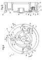
- Figure 1 is a perspective view of a torque limiting assembly according to one embodiment of the present invention with the cam followers engaging the cams in a locked position;
- Figure 2 is a side view of the torque limiting assembly shown in Figure 1;
- Figure 3 is a cross-sectional view of the torque limiting assembly
taken from
Line 3--3 of Figure 2; - Figure 4 is a fragmentary side view of one of the spring arms and cam mechanisms moving out of the locked position; and
- Figure 5 is a side view of the torque limiting assembly with the cam followers released from the cams.
-
- Referring to the Figures, wherein like numerals indicate like or corresponding parts throughout the several views, a transmission and torque limiting assembly for transmitting rotation from a drive to a compressor is shown generally at 10. The
assembly 10 includes a drivenmember 12 for rotation by the drive about anaxis 14 in the direction "D1" shown. Adrive member 16 is disposed about and coaxial with the drivenmember 12. The drivenmember 12 is operatively connected to an engine or other suitable power source by a belt assembly (not shown). - The
assembly 10 also includes amechanism 18 for transmitting rotation from the drivenmember 12 to thedrive member 16. Themechanism 18 also disengages thedrive member 16 from the drivenmember 12 in response to a predetermined reactive force component "FRx" between themembers cams 20, which are presented by the drivenmember 12.Spring arms 22 extend resiliently and spirally from thedrive member 12 todistal ends 24 for engaging thecams 20 to transmit rotation from the drivenmember 12 to thedrive member 16. Using thespring arm 22 shown in Figure 4 as a representative example, eachspring arm 22 also resiliently moves radially in the direction "D2" shown to allow thedistal end 24 to spring past thecam 20 in response to the predetermined reactive force component "FRX". - The
distal ends 24 includecam followers 26 for engaging thecams 20 to transmit the rotation from the drivenmember 12 to thedrive member 16. As is shown in Figure 5, thecam followers 26 are released from thecams 20 in response to the predetermined reactive force component "FRx" as thespring arms 22 move resiliently. Eachcam follower 26 includes apivot 28 that pivotally connects thefollower 26 to one of thedistal ends 24. Eachpivot 28 has arecess 30 for receiving a selected one of thecams 20 to move thecam follower 26 out of a locked position such as that shown in Figure 1. Thecams 20 includeposts 32. Eachrecess 30 is complementary to eachpost 32. - Although any suitable device may be used, the driven
member 12 is apulley 34 with aplanar face 35. Thepulley 34 also includes anouter surface 36 in whichgrooves 37 are formed for engaging a belt (not shown) to operatively connect thepulley 34 to the engine or other power source. Theposts 32 extend axially from theplanar face 35. Ahub 38 is coaxially disposed within thepulley 34. Thespring arms 22 are integrally formed with thehub 38 and extend radially and spirally between thehub 38 and theposts 32. This positions thecam followers 26 so that they can engage theposts 32. - A
stop pin 40 is carried by each of thecam followers 26. Thestop pin 40 reacts with the adjacentdistal end 24 to limit pivotal movement of thecam follower 26 in one direction. This maintains eachcam follower 26 in the locked position shown in Figure 1 to permit transmission of rotation from the drivenmember 12 to thedrive member 16. As is shown in Figures 4 and 5, this also allows pivotal movement of eachcam follower 26 out of the locked position in response to the predetermined reactive force component "FRx". - Obviously, many modifications and variations of the present invention are possible in light of the above teachings. The foregoing description of the invention is provided for the purpose of illustration only and not for the purpose of limitation - the invention being defined by the claims.
Claims (9)
- A transmission and torque limiting assembly (10) for transmitting rotation from a drive to a compressor, said assembly (10) comprising;
a driven member (12) for rotation by the drive about an axis (14),
a drive member (16) disposed about and coaxial with said driven member (12),
a mechanism (18) for transmitting rotation from said driven member (12) to said drive member (16) and for disengaging said drive member (16) from said driven member (12) in response to a predetermined reactive force between said members (12, 16),
said mechanism (18) including cams (20) presented by said driven member (12) and spring arms (22) extending resiliently and spirally from said drive member (16) to distal ends (24) for engaging said cams (20) for transmitting rotation from said driven member (12) to said drive member (16) and for resiliently moving radially to allow said distal ends (24) to spring past said cams (20) in response to the predetermined reactive force. - A torque limiting assembly (10) as recited in claim 1 wherein said distal ends (24) include cam followers (26) for engaging said cams (20) to transmit the rotation from said driven member (12) to said drive member (16) and for releasing from said cams (20) in response to the predetermined reactive force as said spring arms (22) resiliently move.
- A torque limiting assembly (10) as recited in claim 2 and including a pivot (28) pivotally connecting one of said cam followers (26) to each of said distal ends (24).
- A torque limiting assembly (10) as recited in claim 3 and including a stop pin (40) carried by each of said cam followers (26) for reacting with the adjacent distal end (24) to limit pivotal movement of each cam follower (26) in one direction to maintain each cam follower (26) in a locked position for permitting transmission of rotation from said driven member (12) to said drive member (16) and for allowing pivotal movement of each cam follower (26) out of said locked position in response to the predetermined reactive force.
- A torque limiting assembly (10) as recited in claim 4 wherein each of said cam followers (26) includes a recess (30) for receiving a selected one of said cams (20) for moving said cam follower (26) out of said locked position.
- A torque limiting assembly (10) as recited in claim 5 wherein each of said cams (20) comprises a post (32) and said recess is complementary to said post (32).
- A torque limiting assembly (10) as recited in claim 6 wherein said driven member (12) is a pulley (34) with a planar face (35), said posts (32) extending axially from said planar face (35).
- A torque limiting assembly (10) as recited in claim 7 wherein said drive member (16) includes a hub (38) coaxially disposed within said pulley (34), said spring arms (22) integrally formed with said hub (38) and extending radially and spirally between said hub (38) and said posts (32) for positioning said cam followers (26) to engage said posts (32).
- A transmission and torque limiting assembly (10) for transmitting rotation from a drive to a compressor, said assembly (10) comprising;
a pulley (34) having a planar face (35) for rotation by the drive about an axis (14),
a drive member (16) having a hub (38) coaxially disposed within said pulley (34),
a plurality of cam posts (32) extending from said planar face (35),
a plurality of spring arms (22) integrally formed with said hub (38) and extending radially and spirally therefrom to distal ends (24), and
a plurality of cam followers (26) carried by said distal ends (24) for engaging said posts (32) for transmitting rotation from said pulley (34) to said drive member (16) and for causing said spring arms (22) to resiliently move radially to allow said distal ends (24) to spring past said posts (32) for disengaging said drive member (16) from said pulley (34) in response to a predetermined reactive force,
each of said cam followers (26) including a pivot (28) pivotally connecting said cam follower (26) to a selected one of said distal ends (24),
a recess (30) for receiving a selected one of said posts (32), and
a stop pin (40) carried by each of said cam followers (26) for reacting with said selected distal end (24) for limiting pivotal movement of said cam follower (26) in one direction to maintain said cam follower (26) and said selected post (32) in a locked position for permitting transmission of rotation from said pulley (34) to said drive member (16) and for allowing pivotal movement of said cam follower (26) out of said locked position in response to the predetermined reactive force.
Applications Claiming Priority (2)
| Application Number | Priority Date | Filing Date | Title |
|---|---|---|---|
| US731611 | 2003-12-09 | ||
| US10/731,611 US7037201B2 (en) | 2003-12-09 | 2003-12-09 | Torque limiting assembly |
Publications (1)
| Publication Number | Publication Date |
|---|---|
| EP1541889A1 true EP1541889A1 (en) | 2005-06-15 |
Family
ID=34523038
Family Applications (1)
| Application Number | Title | Priority Date | Filing Date |
|---|---|---|---|
| EP04078259A Withdrawn EP1541889A1 (en) | 2003-12-09 | 2004-12-01 | Torque limiting assembly |
Country Status (2)
| Country | Link |
|---|---|
| US (1) | US7037201B2 (en) |
| EP (1) | EP1541889A1 (en) |
Cited By (1)
| Publication number | Priority date | Publication date | Assignee | Title |
|---|---|---|---|---|
| CN103890456A (en) * | 2011-05-10 | 2014-06-25 | 德尔福技术有限公司 | Improved compressor over-torque protection device |
Families Citing this family (5)
| Publication number | Priority date | Publication date | Assignee | Title |
|---|---|---|---|---|
| US8978856B2 (en) * | 2011-05-10 | 2015-03-17 | Delphi Technologies, Inc. | Over-torque protector device for a compressor |
| JP6114681B2 (en) * | 2013-11-21 | 2017-04-12 | 三木プーリ株式会社 | Torque limiter |
| EP3182912B1 (en) * | 2014-08-20 | 2019-05-01 | Tecres S.P.A. | Handle to apply a torque and delivery unit provided with such handle |
| DE102014118700A1 (en) * | 2014-12-16 | 2016-06-16 | Winkelmann Powertrain Components Gmbh & Co. Kg | Device for transmitting torque from an internal combustion engine to an accessory |
| US11002320B2 (en) | 2019-01-14 | 2021-05-11 | Henry C. Chu | Clutch device for compressor |
Citations (5)
| Publication number | Priority date | Publication date | Assignee | Title |
|---|---|---|---|---|
| US2425736A (en) * | 1945-05-17 | 1947-08-19 | Timken Axle Co Detroit | Overload release mechanism |
| US2444530A (en) * | 1943-03-09 | 1948-07-06 | Carroll H Richards | Torque responsive clutch for controlling shifting of gear ratios of transmissions |
| US3203524A (en) * | 1962-07-21 | 1965-08-31 | Fisher & Ludlow Ltd | Overload or torque limiting clutches |
| EP1207316A1 (en) * | 2000-03-29 | 2002-05-22 | Kabushiki Kaisha Toyota Jidoshokki | Power transmission mechanism |
| US20040211639A1 (en) * | 2003-04-25 | 2004-10-28 | Gemofor Inc. | Overload clutch for protecting a drive train |
Family Cites Families (3)
| Publication number | Priority date | Publication date | Assignee | Title |
|---|---|---|---|---|
| US1865559A (en) * | 1930-02-21 | 1932-07-05 | Montgrand Leon De | Mechanical coupling |
| US3724815A (en) * | 1971-06-03 | 1973-04-03 | C Kc Kinnon Corp | Hoist operating hand wheel incorporating an overload protection mechanism |
| JP2000205293A (en) * | 1999-01-14 | 2000-07-25 | Toyota Autom Loom Works Ltd | Power transmission mechanism |
-
2003
- 2003-12-09 US US10/731,611 patent/US7037201B2/en not_active Expired - Fee Related
-
2004
- 2004-12-01 EP EP04078259A patent/EP1541889A1/en not_active Withdrawn
Patent Citations (5)
| Publication number | Priority date | Publication date | Assignee | Title |
|---|---|---|---|---|
| US2444530A (en) * | 1943-03-09 | 1948-07-06 | Carroll H Richards | Torque responsive clutch for controlling shifting of gear ratios of transmissions |
| US2425736A (en) * | 1945-05-17 | 1947-08-19 | Timken Axle Co Detroit | Overload release mechanism |
| US3203524A (en) * | 1962-07-21 | 1965-08-31 | Fisher & Ludlow Ltd | Overload or torque limiting clutches |
| EP1207316A1 (en) * | 2000-03-29 | 2002-05-22 | Kabushiki Kaisha Toyota Jidoshokki | Power transmission mechanism |
| US20040211639A1 (en) * | 2003-04-25 | 2004-10-28 | Gemofor Inc. | Overload clutch for protecting a drive train |
Cited By (2)
| Publication number | Priority date | Publication date | Assignee | Title |
|---|---|---|---|---|
| CN103890456A (en) * | 2011-05-10 | 2014-06-25 | 德尔福技术有限公司 | Improved compressor over-torque protection device |
| CN103890456B (en) * | 2011-05-10 | 2016-08-17 | 马勒国际有限公司 | Improved compressor over-torque protection device |
Also Published As
| Publication number | Publication date |
|---|---|
| US7037201B2 (en) | 2006-05-02 |
| US20050124418A1 (en) | 2005-06-09 |
Similar Documents
| Publication | Publication Date | Title |
|---|---|---|
| CN104285071B (en) | Pin and pawl type two-way overrunning clutch | |
| US7037201B2 (en) | Torque limiting assembly | |
| US6910969B2 (en) | Power transmission apparatus for clutchless compressor | |
| US5085305A (en) | Cam-operated, positive clutch with electromagnetic actuator | |
| US5582071A (en) | Reverse gear squeal-preventing device | |
| EP1751442B1 (en) | Improved torque overload clutch | |
| EP2006565A1 (en) | Gear apparatus | |
| US6309304B1 (en) | Internal torque limiter for a parallel indexer | |
| KR20020081453A (en) | Centrifugal clutch | |
| CN216006344U (en) | Clothes treatment equipment and clutch assembly thereof | |
| JP2942488B2 (en) | Lift-off type motor with one-way clutch mechanism | |
| US6942082B1 (en) | Drive coupling | |
| CZ2003186A3 (en) | Belt drive ring cvt coupler | |
| CN106481691B (en) | Bi-directional overrunning clutch and power transmission system including the same | |
| US4993992A (en) | Single stage engagement coupling | |
| EP2707626B1 (en) | Improved over-torque protector device for a compressor | |
| CN113446327B (en) | Clutch | |
| US6460670B2 (en) | Clutch for blade engagement | |
| EP1179678A3 (en) | Power transmitting mechanism | |
| JPH0625707Y2 (en) | Oldham fittings | |
| CN221120699U (en) | Power connection structure for vascular intervention surgical robot and surgical robot | |
| CN2480616Y (en) | Single direction coaster with inner friction shoe | |
| CN116464716B (en) | Clutch | |
| CN100406716C (en) | Starting mechanism for engine of motorcycle | |
| JP2000018157A (en) | Power transmission device for clutchless compressor |
Legal Events
| Date | Code | Title | Description |
|---|---|---|---|
| PUAI | Public reference made under article 153(3) epc to a published international application that has entered the european phase |
Free format text: ORIGINAL CODE: 0009012 |
|
| AK | Designated contracting states |
Kind code of ref document: A1 Designated state(s): AT BE BG CH CY CZ DE DK EE ES FI FR GB GR HU IE IS IT LI LT LU MC NL PL PT RO SE SI SK TR |
|
| AX | Request for extension of the european patent |
Extension state: AL BA HR LV MK YU |
|
| 17P | Request for examination filed |
Effective date: 20051215 |
|
| AKX | Designation fees paid |
Designated state(s): AT BE BG CH CY CZ DE DK EE ES FI FR GB GR HU IE IS IT LI LT LU MC NL PL PT RO SE SI SK TR |
|
| STAA | Information on the status of an ep patent application or granted ep patent |
Free format text: STATUS: THE APPLICATION IS DEEMED TO BE WITHDRAWN |
|
| 18D | Application deemed to be withdrawn |
Effective date: 20100422 |