EP1541874B1 - Hydraulic control valve - Google Patents
Hydraulic control valve Download PDFInfo
- Publication number
- EP1541874B1 EP1541874B1 EP20040257562 EP04257562A EP1541874B1 EP 1541874 B1 EP1541874 B1 EP 1541874B1 EP 20040257562 EP20040257562 EP 20040257562 EP 04257562 A EP04257562 A EP 04257562A EP 1541874 B1 EP1541874 B1 EP 1541874B1
- Authority
- EP
- European Patent Office
- Prior art keywords
- valve
- spool
- components
- interface
- guide
- Prior art date
- Legal status (The legal status is an assumption and is not a legal conclusion. Google has not performed a legal analysis and makes no representation as to the accuracy of the status listed.)
- Expired - Lifetime
Links
Images

Classifications
-
- F—MECHANICAL ENGINEERING; LIGHTING; HEATING; WEAPONS; BLASTING
- F15—FLUID-PRESSURE ACTUATORS; HYDRAULICS OR PNEUMATICS IN GENERAL
- F15B—SYSTEMS ACTING BY MEANS OF FLUIDS IN GENERAL; FLUID-PRESSURE ACTUATORS, e.g. SERVOMOTORS; DETAILS OF FLUID-PRESSURE SYSTEMS, NOT OTHERWISE PROVIDED FOR
- F15B11/00—Servomotor systems without provision for follow-up action ; Circuits therefor
- F15B11/02—Systems essentially incorporating special features for controlling the speed or the actuating force of an output member
- F15B11/028—Systems essentially incorporating special features for controlling the speed or the actuating force of an output member for controlling the actuating force
- F15B11/036—Systems essentially incorporating special features for controlling the speed or the actuating force of an output member for controlling the actuating force by means of servomotors having a plurality of working chambers
-
- F—MECHANICAL ENGINEERING; LIGHTING; HEATING; WEAPONS; BLASTING
- F15—FLUID-PRESSURE ACTUATORS; HYDRAULICS OR PNEUMATICS IN GENERAL
- F15B—SYSTEMS ACTING BY MEANS OF FLUIDS IN GENERAL; FLUID-PRESSURE ACTUATORS, e.g. SERVOMOTORS; DETAILS OF FLUID-PRESSURE SYSTEMS, NOT OTHERWISE PROVIDED FOR
- F15B11/00—Servomotor systems without provision for follow-up action ; Circuits therefor
- F15B11/02—Systems essentially incorporating special features for controlling the speed or the actuating force of an output member
- F15B11/028—Systems essentially incorporating special features for controlling the speed or the actuating force of an output member for controlling the actuating force
- F15B11/036—Systems essentially incorporating special features for controlling the speed or the actuating force of an output member for controlling the actuating force by means of servomotors having a plurality of working chambers
- F15B11/0365—Tandem constructions
-
- F—MECHANICAL ENGINEERING; LIGHTING; HEATING; WEAPONS; BLASTING
- F15—FLUID-PRESSURE ACTUATORS; HYDRAULICS OR PNEUMATICS IN GENERAL
- F15B—SYSTEMS ACTING BY MEANS OF FLUIDS IN GENERAL; FLUID-PRESSURE ACTUATORS, e.g. SERVOMOTORS; DETAILS OF FLUID-PRESSURE SYSTEMS, NOT OTHERWISE PROVIDED FOR
- F15B2211/00—Circuits for servomotor systems
- F15B2211/30—Directional control
- F15B2211/305—Directional control characterised by the type of valves
- F15B2211/30525—Directional control valves, e.g. 4/3-directional control valve
-
- F—MECHANICAL ENGINEERING; LIGHTING; HEATING; WEAPONS; BLASTING
- F15—FLUID-PRESSURE ACTUATORS; HYDRAULICS OR PNEUMATICS IN GENERAL
- F15B—SYSTEMS ACTING BY MEANS OF FLUIDS IN GENERAL; FLUID-PRESSURE ACTUATORS, e.g. SERVOMOTORS; DETAILS OF FLUID-PRESSURE SYSTEMS, NOT OTHERWISE PROVIDED FOR
- F15B2211/00—Circuits for servomotor systems
- F15B2211/60—Circuit components or control therefor
- F15B2211/63—Electronic controllers
- F15B2211/6303—Electronic controllers using input signals
- F15B2211/6336—Electronic controllers using input signals representing a state of the output member, e.g. position, speed or acceleration
-
- F—MECHANICAL ENGINEERING; LIGHTING; HEATING; WEAPONS; BLASTING
- F15—FLUID-PRESSURE ACTUATORS; HYDRAULICS OR PNEUMATICS IN GENERAL
- F15B—SYSTEMS ACTING BY MEANS OF FLUIDS IN GENERAL; FLUID-PRESSURE ACTUATORS, e.g. SERVOMOTORS; DETAILS OF FLUID-PRESSURE SYSTEMS, NOT OTHERWISE PROVIDED FOR
- F15B2211/00—Circuits for servomotor systems
- F15B2211/70—Output members, e.g. hydraulic motors or cylinders or control therefor
- F15B2211/705—Output members, e.g. hydraulic motors or cylinders or control therefor characterised by the type of output members or actuators
- F15B2211/7051—Linear output members
- F15B2211/7055—Linear output members having more than two chambers
- F15B2211/7056—Tandem cylinders
-
- F—MECHANICAL ENGINEERING; LIGHTING; HEATING; WEAPONS; BLASTING
- F15—FLUID-PRESSURE ACTUATORS; HYDRAULICS OR PNEUMATICS IN GENERAL
- F15B—SYSTEMS ACTING BY MEANS OF FLUIDS IN GENERAL; FLUID-PRESSURE ACTUATORS, e.g. SERVOMOTORS; DETAILS OF FLUID-PRESSURE SYSTEMS, NOT OTHERWISE PROVIDED FOR
- F15B2211/00—Circuits for servomotor systems
- F15B2211/80—Other types of control related to particular problems or conditions
- F15B2211/86—Control during or prevention of abnormal conditions
- F15B2211/863—Control during or prevention of abnormal conditions the abnormal condition being a hydraulic or pneumatic failure
- F15B2211/8636—Circuit failure, e.g. valve or hose failure
-
- F—MECHANICAL ENGINEERING; LIGHTING; HEATING; WEAPONS; BLASTING
- F15—FLUID-PRESSURE ACTUATORS; HYDRAULICS OR PNEUMATICS IN GENERAL
- F15B—SYSTEMS ACTING BY MEANS OF FLUIDS IN GENERAL; FLUID-PRESSURE ACTUATORS, e.g. SERVOMOTORS; DETAILS OF FLUID-PRESSURE SYSTEMS, NOT OTHERWISE PROVIDED FOR
- F15B2211/00—Circuits for servomotor systems
- F15B2211/80—Other types of control related to particular problems or conditions
- F15B2211/875—Control measures for coping with failures
- F15B2211/8757—Control measures for coping with failures using redundant components or assemblies
-
- Y—GENERAL TAGGING OF NEW TECHNOLOGICAL DEVELOPMENTS; GENERAL TAGGING OF CROSS-SECTIONAL TECHNOLOGIES SPANNING OVER SEVERAL SECTIONS OF THE IPC; TECHNICAL SUBJECTS COVERED BY FORMER USPC CROSS-REFERENCE ART COLLECTIONS [XRACs] AND DIGESTS
- Y10—TECHNICAL SUBJECTS COVERED BY FORMER USPC
- Y10T—TECHNICAL SUBJECTS COVERED BY FORMER US CLASSIFICATION
- Y10T137/00—Fluid handling
- Y10T137/5762—With leakage or drip collecting
-
- Y—GENERAL TAGGING OF NEW TECHNOLOGICAL DEVELOPMENTS; GENERAL TAGGING OF CROSS-SECTIONAL TECHNOLOGIES SPANNING OVER SEVERAL SECTIONS OF THE IPC; TECHNICAL SUBJECTS COVERED BY FORMER USPC CROSS-REFERENCE ART COLLECTIONS [XRACs] AND DIGESTS
- Y10—TECHNICAL SUBJECTS COVERED BY FORMER USPC
- Y10T—TECHNICAL SUBJECTS COVERED BY FORMER US CLASSIFICATION
- Y10T137/00—Fluid handling
- Y10T137/8593—Systems
- Y10T137/86493—Multi-way valve unit
- Y10T137/86574—Supply and exhaust
- Y10T137/86622—Motor-operated
- Y10T137/8663—Fluid motor
-
- Y—GENERAL TAGGING OF NEW TECHNOLOGICAL DEVELOPMENTS; GENERAL TAGGING OF CROSS-SECTIONAL TECHNOLOGIES SPANNING OVER SEVERAL SECTIONS OF THE IPC; TECHNICAL SUBJECTS COVERED BY FORMER USPC CROSS-REFERENCE ART COLLECTIONS [XRACs] AND DIGESTS
- Y10—TECHNICAL SUBJECTS COVERED BY FORMER USPC
- Y10T—TECHNICAL SUBJECTS COVERED BY FORMER US CLASSIFICATION
- Y10T137/00—Fluid handling
- Y10T137/8593—Systems
- Y10T137/86493—Multi-way valve unit
- Y10T137/86574—Supply and exhaust
- Y10T137/8667—Reciprocating valve
- Y10T137/86694—Piston valve
- Y10T137/8671—With annular passage [e.g., spool]
Definitions
- This invention relates to hydraulic control valves primarily, but not exclusively, for controlling hydraulic actuators for primary flight control surfaces of aircraft.
- Dual actuators can be in the form of two separate hydraulic actuators, although more often are in the form of dual-tandem actuators in which a single piston rod and output member carries two spaced pistons, each piston operating in a respective hydraulic cylinder.
- the two cylinders of the dual actuator arrangement are supplied separately with hydraulic fluid under pressure from respective discreet pressure sources through the intermediary of respective hydraulic control valves.
- the capacity of each hydraulic supply and piston and cylinder arrangement is such that the primary flight control surface can be operated by either piston operating alone, and thus the overall system can safely accommodate failure of one or other of the hydraulic supplies, control valves, or piston and cylinder arrangements.
- the tandem valve of Figure 1 includes an outer valve block 11 containing a valve body, usually referred to as a valve guide 12, slidably receiving a valve spool 13.
- Figure 1 also illustrates a dual-tandem actuator 14 having first and second cylinders 15, 16 housing respective pistons 17, 18 carried by a common piston rod 19.
- One end of the piston rod 19 has a coupling 21 to the primary flight control surface, and the position of the piston rod 19 relative to a fixed datum position is measured by an LVDT (Linear Variable Differential Transformer) 22 or other sensor the output of which is supplied to a control system of the aircraft.
- LVDT Linear Variable Differential Transformer
- the actuator 14 is a double acting actuator in the sense that the piston rod 19 can be driven to the left or the right (in Figure 1) usually to deploy or retract the associated flight control surface, by admission of hydraulic fluid under pressure to appropriate ends of the cylinders 15, 16.
- the invention is applicable also in relation to single acting actuators wherein the actuator is hydraulically driven in a deploy direction and otherwise returned in the retract direction. Moreover rather than the two hydraulic circuits controlling pistons of a dual-tandem actuator they could control respective separate actuators which would thus operate in unison.
- Each cylinder 15, 16 has respective flow and return lines 23 a , 23 b and 24 a , and 24 b connected to respective first and second control ports 25 a , 25 b and 26 a , 26 b of the valve guide 12.
- a supply port 28 Positioned between the first and second control ports 25 a , 25 b is a supply port 28 connected to a first hydraulic supply line 33 for hydraulic fluid under pressure.
- a supply port 29 is disposed between the ports 26 a and 26 b and is connected to a hydraulic supply line 34 connected to a second source of hydraulic pressure.
- the valve guide 12 Outwardly, beyond the second control port 25 b , the valve guide 12 has a return port 31 a , and a second return port 31 b is disposed between the control port 25 a and a notional mid-plane 27 of the valve guide 12.
- the return ports 31 a and 31 b are connected to a common low pressure return line 35.
- the valve guide to the right of the plane 27 (the guide of the right-hand control valve of the tandem valve) is similarly provided with first and second return ports 32 a , 32 b connected to a common low pressure return line 36.
- the spool 13 of the tandem valve can be viewed as two integral spools, one for each valve, and each has a centrally disposed gallery 43, 46 which, dependent upon the axial position of the spool, can connect the respective supply ports 28, 29 to one or other of the respective first and second control ports 25 a , 25 b and 26 a , 26 b .
- Movement of the spool 13 to the left from the position shown in Figure 1 supplies hydraulic fluid under pressure from the supply line 33 to the left-hand side of the piston 17, while opening the line 23 b from the right-hand side of the piston to the low pressure return line 35. Simultaneously, and in synchronism therewith, the left-hand side of the piston 18 is exposed to hydraulic pressure from the supply line 34 through the line 24 a , and the right-hand side of the piston 18 is connected to the low pressure return line 36 through the line 24 b . Thus the piston rod 19 is moved to the right to deploy the primary flight control surface.
- Each of the ports 25, 26, 28, 29, 31, 32 is defined in the valve guide 12 by a circumferential, rectangular cross-section groove in the outer surface of the valve guide.
- the grooves are closed so as to define annular galleries by the inner surface of the valve block 11.
- the wall of the guide 12 has a plurality of radial drillings extending inwardly from the channels defining the various ports, and opening at the inner face of the guide 12 to coact with the galleries of the spool 13.
- the spool 13 is moved within the guide 12 by the application of pressurised hydraulic fluid to control chambers 38, 39 at opposite ends respectively of the spool 13.
- each annular port defined between the guide 12 and the valve block 11 there is provided an "O"-ring seal which seals the interface of the guide 12 and the valve block 11 to prevent leakage along that interface.
- the large central land of the spool 13, between the galleries 44 b and 47 a is provided with an 'O'-ring seal sealing the sliding interface of the spool 13 and the guide 12 to prevent leakage between the galleries 44 b and 47 a along that interface. It will be recognised that it is most important, for safety considerations, to preserve the isolation of the two hydraulic systems and in normal operation the arrangement, including the 'O'-ring seals, achieves such isolation of the systems from one another.
- valve block 11 may have a drain drilling aligned on plane 27 and the spool 13 will have a pair of spaced "O"-ring seals on its central land, the drilling draining any leakage past the seals from the galleries 44 b , 47 a .
- the block 11 may be formed in two halves divided on the plane 27.
- US 3893484 describes a valve arrangement having two spools urged apart by a spring, and an actuator operable to move the spools.
- a tandem hydraulic valve comprising first and second axially aligned valve spools slidable in a valve guide to control, in use, the connection between respective ports of the valve guide, said first and second spools being formed as separate components and being rigidly axially interconnected, to move in unison, by an axial connection component, and, the interface of said first and second spools being connected to a predefined external leakage path.
- valve guide comprises first and second axially aligned and separately formed valve guide components, said first valve guide component cooperating with said first valve spool, said second valve guide component cooperating with said second valve spool, and said first and second valve guide components being held in a fixed axial relationship to one another with the axial interface of said first and second valve guide components forming part of said predefined leakage path.
- said axial connection component extends through both spool components and bears against the outer axial ends of the spool components.
- said axial connection component comprises an elongate sleeve which extends through the spool components and an elongate element which extends through said elongate sleeve and bears against the opposite axial ends of the sleeve.
- said leakage path is visible at the exterior of the valve to provide a visual indicator of a spool failure.
- said leakage path is a leakage path to atmosphere.
- FIG. 1 is a diagrammatic axial cross-sectional view of a previously proposed form of tandem valve.
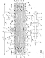
- Figure 2 is a view similar to Figure 1 of a tandem valve in accordance with a first example of the present invention.
- the tandem valve comprises a valve block 11 formed as two axially aligned halves 11 a , 11 b which abut axially at the mid-plane 27 of the tandem valve and define an interface 51 in the plane 27.
- a valve guide 12 Received within the valve block 11 is a valve guide 12 which is formed as two axially aligned separate components 12 a , 12 b and which are held in axial abutment by the block 11.
- the guide components 12 a , 12 b abut at an interface 52 disposed in the plane 27 and each of the components 12 a , 12 b includes adjacent to the interface 52 an integral peripheral outwardly extending flange 12 c , 12 d , the flanges 12 c , 12 d being held in facial abutment by being received within appropriately recessed regions of the end faces of the block halves 11 a , 11 b .
- the manner in which the guide halves are held axially in place is not of importance to the invention, but it will be recognised that securing the block halves 11 a , 11 b together locks the valve guide components 12 a , 12 b together so that functionally they act as a single valve guide serving both valves of the tandem valve.
- the interface 51 of the block communicates with the interface 52 of the valve guide components and the interface 51 is open to atmosphere at its outer periphery. It can be seen that the ports and drillings of the valve guide 12 are as described above in relation to Figure 1.
- valve spool 13 Slidably received within the valve guide 12 a , 12 b is a valve spool 13 which is defined by first and second valve spool components 13 a , 13 b formed separately from one another, but held in axial alignment, with their axial end faces abutting, by a securing assembly 55.
- the spool components 13 a , 13 b abut at an interface 54 disposed within the plane 27 when the spool is at the mid-point of its travel.
- the axially abutting end regions of the spool components 13 a , 13 b define a divided land equivalent to the large central land of the one-piece spool of Figure 1.
- the land of the spool 13 a , 13 b is divided by the interface 54, and each half of the land is provided with an O-ring seal 56, 57 to seal the sliding interface of the central land of the spool with the central region of the valve guide 12 a , 12 b .
- the spacing of the seals 56, 57 is selected, in relation to the maximum throw of the spool in either direction from the central position illustrated in Figure 2, such that neither seal rides over the interface 52 of the valve block components 12 a , 12 b .
- the interface 54 of the spool components 13 a , 13 b is hydraulically connected to the interface 52 of the guide components, and thereby connected to atmosphere by way of the interface 51 of the block halves.
- the spool component 13 a has galleries 43, 44 a , 44 b and dividing lands 45 a , 45 b and the spool component 13 b similarly has galleries 46, 47 a , 47 b separated by lands 48 a and 48 b .
- the two halves of the spool 13 a , 13 b are rigidly interconnected so as to be axially immovable relative to one another, and thus the spool 13 a , 13 b operates in conjunction with the guide 12 a , 12 b in exactly the same manner as the spool and block of the construction shown in Figure 1.
- Each of the spool components 13 a , 13 b is in the form of a hollow metal sleeve, and extending through the spool components 13 a , 13 b is a coaxial securing sleeve 58 forming one part of the securing assembly 55 of the spool components.
- the sleeve 58 protrudes at its opposite axial ends from the outer ends of the components 13 a and 13 b respectively, and each protruding end of the sleeve 58 is externally screw-threaded, and receives a securing nut 59 which is tightened to bear against the adjacent end of the respective spool component so that the two spool components are moved axially into abutment at the interface 54, and are held in abutting engagement thereby.
- O-ring seals carried in external peripheral grooves of the sleeve 58 and positioned adjacent at the outer ends of the sleeve 58 seal the cylindrical interface of the sleeve 58 and the spool components 13 a , 13 b .
- Extending through the sleeve 58 is a second component of the securing assembly 55 in the form of an elongate solid metal rod 61 opposite axial ends of which protrude beyond the opposite axial ends of the sleeve 58 and are screw-threaded to receive securing nuts 62.
- the securing nuts 62 are tightened against their respective abutting end faces of the sleeve 58 so that the rod 61 is placed in slight tension within the sleeve 58.
- 'O'-ring seals received in respective circumferential grooves in the rod 61, adjacent its opposite axial ends, seal the cylindrical interface of the rod 61 and the sleeve 58.
- a radial through bore 63 in the wall of the sleeve 58 places the cylindrical interface of the sleeve 58 and the spool components 13 a , between the respective O-ring seals, in communication with the cylindrical interface of the rod 61 and the sleeve 58 between their 'O'-ring seals.
- the spool assembly consisting of the components 13 a , 13 b together with the securing assembly 55 operates as a single unitary component, and the operation of the two separate control valves defined by the tandem valve operates exactly as described above with reference to Figure 1.
- the failure mode of the spool 13 of the tandem valve described with reference to Figure 1 in which a fracture line joins the gallery 44 b and the gallery 47 a , cannot occur in the valve of Figure 2 since the galleries 44 b and 47 a are formed in separate spool components.
- Fracture of the spool component 13 a at the inner-most end of the gallery 44 b will connect gallery 44 b with the drain interface 51 by way of fluid leakage along the cylindrical interface of the sleeve 58 and the spool component 13 a , the interface 54 of the spool components, and the interface 52 of the valve block components.
- the gallery 44 b would leak to atmosphere at the exterior of the block 11.
- a similar fracture of the spool component 13 b would connect the gallery 47 a to the drain interface 51 by way of the interface of the sleeve 58 and the spool component 13 b , the interface 54, and the interface 52.
- fluid from the gallery 47 a would flow to atmosphere at the block exterior, and not to the gallery 44b.
- the interfaces 54, 52 and 51 can be relieved, by radial grooves in their faces, to ensure that there is relatively low flow resistance in the path to atmosphere.
- the block will have an externally vented gallery or annular recess communicating in use with the interface 52.
- a one-piece valve guide 12 could be utilised with a two part spool 13 and in such a construction the guide 12 will have a gallery or annular recess communicating with the interface 54 of the spool and vented to the exterior of the valve block 11 so that a leak is visible.
- the hydraulic circuits of the first and second piston and cylinder arrangements 15, 17; 16, 18 are maintained isolated from one another even in a spool fracture fault situation.
- leakage of hydraulic fluid (usually oil) at the exterior of the valve block will alert service personnel to the fault, while permitting the undamaged half of the valve to function normally to control its respective cylinder of the dual-tandem actuator 14 so that notwithstanding a fault in one of the spool components 13 a , 13 b control over the associated flight control surface or other component driven by the actuator 14 is maintained.
- the nuts 59 bearing against the outer axial ends of the spool components 13 a , 13 b , and also the nuts 62 bearing against the ends of the sleeve 58 may be replaced by alternative load bearing securing means for example integral heads or flanges formed after assembly of the components or welds, conveniently laser welds, also formed after assembly.
Landscapes
- Engineering & Computer Science (AREA)
- Physics & Mathematics (AREA)
- Fluid Mechanics (AREA)
- Mechanical Engineering (AREA)
- General Engineering & Computer Science (AREA)
- Multiple-Way Valves (AREA)
- Valve Housings (AREA)
Description
- This invention relates to hydraulic control valves primarily, but not exclusively, for controlling hydraulic actuators for primary flight control surfaces of aircraft.
- It is usual for the primary flight control surfaces of an aircraft, for example elevators, rudders, and ailerons, to be actuated by dual hydraulic actuators. Dual actuators can be in the form of two separate hydraulic actuators, although more often are in the form of dual-tandem actuators in which a single piston rod and output member carries two spaced pistons, each piston operating in a respective hydraulic cylinder. The two cylinders of the dual actuator arrangement are supplied separately with hydraulic fluid under pressure from respective discreet pressure sources through the intermediary of respective hydraulic control valves. The capacity of each hydraulic supply and piston and cylinder arrangement is such that the primary flight control surface can be operated by either piston operating alone, and thus the overall system can safely accommodate failure of one or other of the hydraulic supplies, control valves, or piston and cylinder arrangements.
- Although the two hydraulic control valves controlling the cylinders of a dual actuator could be completely separate from one another it is essential that the cylinders of the dual actuator are operated in unison, and any lack of synchronisation in the operation of the two valves could result in an undesirable "force fight" as part of the dual actuator tries to perform an operation not being performed by the other part of the actuator. In order to avoid such difficulties a tandem control valve of the kind illustrated in Figure 1 of the accompanying drawings has been proposed. The tandem valve of Figure 1 includes an
outer valve block 11 containing a valve body, usually referred to as avalve guide 12, slidably receiving avalve spool 13. Figure 1 also illustrates a dual-tandem actuator 14 having first andsecond cylinders respective pistons common piston rod 19. One end of thepiston rod 19 has acoupling 21 to the primary flight control surface, and the position of thepiston rod 19 relative to a fixed datum position is measured by an LVDT (Linear Variable Differential Transformer) 22 or other sensor the output of which is supplied to a control system of the aircraft. In the embodiment shown thecylinders actuator 14 is a double acting actuator in the sense that thepiston rod 19 can be driven to the left or the right (in Figure 1) usually to deploy or retract the associated flight control surface, by admission of hydraulic fluid under pressure to appropriate ends of thecylinders - Each
cylinder return lines second control ports valve guide 12. Positioned between the first andsecond control ports supply port 28 connected to a firsthydraulic supply line 33 for hydraulic fluid under pressure. Similarly asupply port 29 is disposed between theports hydraulic supply line 34 connected to a second source of hydraulic pressure. Outwardly, beyond thesecond control port 25b, thevalve guide 12 has areturn port 31a, and asecond return port 31b is disposed between thecontrol port 25a and anotional mid-plane 27 of thevalve guide 12. Thereturn ports pressure return line 35. The valve guide to the right of the plane 27 (the guide of the right-hand control valve of the tandem valve) is similarly provided with first andsecond return ports 32a, 32b connected to a common lowpressure return line 36. - The
spool 13 of the tandem valve can be viewed as two integral spools, one for each valve, and each has a centrally disposedgallery respective supply ports second control ports centre gallery second return galleries - When
supply gallery 43interconnects supply port 28 andcontrol port 25a then returngallery 44binterconnects return port 31b andcontrol port 25b. Similarly with the spool moved in the opposite direction, to the right, andsupply gallery 43 connectssupply port 28 andcontrol port 25b thenreturn gallery 44ainterconnects return port 31a andcontrol port 25a. Moreover, it will be understood that whilegallery 43interconnects ports supply gallery 46 will be interconnectingsupply port 29 withcontrol port 26a andreturn gallery 47b will be connectingreturn port 32b withcontrol port 26b. Similarly whensupply gallery 46interconnects supply port 29 withcontrol port 26b then return gallery 47a connects return port 32a andcontrol port 26a. - It will be recognised therefore that with the tandem valve in the position shown in Figure 1 the lands of the spool which separate the
gallery 43 from thegallery 44a and thegallery 43 from thegallery 44b, are in position closing thecontrol ports spool 13 close thecontrol ports cylinders pistons piston rod 19 is immovable, there being no flow path along thehydraulic lines - Movement of the
spool 13 to the left from the position shown in Figure 1 supplies hydraulic fluid under pressure from thesupply line 33 to the left-hand side of thepiston 17, while opening theline 23b from the right-hand side of the piston to the lowpressure return line 35. Simultaneously, and in synchronism therewith, the left-hand side of thepiston 18 is exposed to hydraulic pressure from thesupply line 34 through the line 24a, and the right-hand side of thepiston 18 is connected to the lowpressure return line 36 through theline 24b. Thus thepiston rod 19 is moved to the right to deploy the primary flight control surface. - Movement of the
spool 13 to the right, through the full extent of its travel, reverses the connections to thelines pistons supply lines pistons pressure return lines piston rod 19 to the left and retracting the associated primary flight control surface. - Each of the
ports valve guide 12 by a circumferential, rectangular cross-section groove in the outer surface of the valve guide. The grooves are closed so as to define annular galleries by the inner surface of thevalve block 11. The wall of theguide 12 has a plurality of radial drillings extending inwardly from the channels defining the various ports, and opening at the inner face of theguide 12 to coact with the galleries of thespool 13. Thespool 13 is moved within theguide 12 by the application of pressurised hydraulic fluid tocontrol chambers spool 13. Application of pressure to thechamber 38 while venting thechamber 39 moves thespool 13 to the right in Figure 1 against the action of areturn spring 41, while application of control pressure to thechamber 39 while venting thechamber 38 moves the spool to the left against the action of afurther return spring 42. - It can be seen that at each side of each annular port defined between the
guide 12 and thevalve block 11 there is provided an "O"-ring seal which seals the interface of theguide 12 and thevalve block 11 to prevent leakage along that interface. Furthermore, the large central land of thespool 13, between thegalleries 44b and 47a, is provided with an 'O'-ring seal sealing the sliding interface of thespool 13 and theguide 12 to prevent leakage between thegalleries 44b and 47a along that interface. It will be recognised that it is most important, for safety considerations, to preserve the isolation of the two hydraulic systems and in normal operation the arrangement, including the 'O'-ring seals, achieves such isolation of the systems from one another. However, it has been recognised that there is a possible fault condition of the tandem valve of Figure 1 in which thespool 13 fractures along a line joining thegallery 44b and the gallery 47a. Such a fracture line is shown at 50 in Figure 1 and could cause leakage from thegallery 44b to the gallery 47a and vice versa leading to cross contamination of the two separate hydraulic systems and possible undesirable pressurisation or loss of pressurisation of a cylinder. - In practice the
valve block 11 may have a drain drilling aligned onplane 27 and thespool 13 will have a pair of spaced "O"-ring seals on its central land, the drilling draining any leakage past the seals from thegalleries 44b, 47a. Moreover theblock 11 may be formed in two halves divided on theplane 27. -
US 3893484 describes a valve arrangement having two spools urged apart by a spring, and an actuator operable to move the spools. - It is an object of the present invention to provide a tandem valve wherein such problems are minimised or obviated.
- In accordance with the present invention there is provided a tandem hydraulic valve comprising first and second axially aligned valve spools slidable in a valve guide to control, in use, the connection between respective ports of the valve guide, said first and second spools being formed as separate components and being rigidly axially interconnected, to move in unison, by an axial connection component, and, the interface of said first and second spools being connected to a predefined external leakage path. Preferably said valve guide comprises first and second axially aligned and separately formed valve guide components, said first valve guide component cooperating with said first valve spool, said second valve guide component cooperating with said second valve spool, and said first and second valve guide components being held in a fixed axial relationship to one another with the axial interface of said first and second valve guide components forming part of said predefined leakage path.
- Preferably said axial connection component extends through both spool components and bears against the outer axial ends of the spool components.
- Desirably said axial connection component comprises an elongate sleeve which extends through the spool components and an elongate element which extends through said elongate sleeve and bears against the opposite axial ends of the sleeve.
- Preferably said leakage path is visible at the exterior of the valve to provide a visual indicator of a spool failure.
- Desirably said leakage path is a leakage path to atmosphere.
- In the accompanying drawings Figure 1 is a diagrammatic axial cross-sectional view of a previously proposed form of tandem valve; and,
- Figure 2 is a view similar to Figure 1 of a tandem valve in accordance with a first example of the present invention.
- Referring now to Figure 2, components common to the valve described above with reference to Figure 1 carry the same reference numerals.
- In Figure 2 it can be seen that the tandem valve comprises a
valve block 11 formed as two axially alignedhalves 11a, 11b which abut axially at the mid-plane 27 of the tandem valve and define aninterface 51 in theplane 27. Received within thevalve block 11 is avalve guide 12 which is formed as two axially alignedseparate components block 11. Theguide components interface 52 disposed in theplane 27 and each of thecomponents interface 52 an integral peripheral outwardly extendingflange 12c, 12d, theflanges 12c, 12d being held in facial abutment by being received within appropriately recessed regions of the end faces of theblock halves 11a, 11b. The manner in which the guide halves are held axially in place is not of importance to the invention, but it will be recognised that securing theblock halves 11a, 11b together locks thevalve guide components - The
interface 51 of the block communicates with theinterface 52 of the valve guide components and theinterface 51 is open to atmosphere at its outer periphery. It can be seen that the ports and drillings of thevalve guide 12 are as described above in relation to Figure 1. - Slidably received within the
valve guide valve spool 13 which is defined by first and secondvalve spool components assembly 55. Thespool components interface 54 disposed within theplane 27 when the spool is at the mid-point of its travel. The axially abutting end regions of thespool components spool interface 54, and each half of the land is provided with an O-ring seal valve guide seals interface 52 of thevalve block components interface 54 of thespool components interface 52 of the guide components, and thereby connected to atmosphere by way of theinterface 51 of the block halves. - It can be seen that the
spool component 13a hasgalleries lands spool component 13b similarly hasgalleries lands spool spool guide - Each of the
spool components spool components sleeve 58 forming one part of the securingassembly 55 of the spool components. Thesleeve 58 protrudes at its opposite axial ends from the outer ends of thecomponents sleeve 58 is externally screw-threaded, and receives a securingnut 59 which is tightened to bear against the adjacent end of the respective spool component so that the two spool components are moved axially into abutment at theinterface 54, and are held in abutting engagement thereby. O-ring seals carried in external peripheral grooves of thesleeve 58 and positioned adjacent at the outer ends of thesleeve 58 seal the cylindrical interface of thesleeve 58 and thespool components - Extending through the
sleeve 58 is a second component of the securingassembly 55 in the form of an elongatesolid metal rod 61 opposite axial ends of which protrude beyond the opposite axial ends of thesleeve 58 and are screw-threaded to receive securing nuts 62. The securingnuts 62 are tightened against their respective abutting end faces of thesleeve 58 so that therod 61 is placed in slight tension within thesleeve 58. 'O'-ring seals received in respective circumferential grooves in therod 61, adjacent its opposite axial ends, seal the cylindrical interface of therod 61 and thesleeve 58. A radial throughbore 63 in the wall of thesleeve 58 places the cylindrical interface of thesleeve 58 and thespool components 13a, between the respective O-ring seals, in communication with the cylindrical interface of therod 61 and thesleeve 58 between their 'O'-ring seals. - During normal operation of the valve illustrated in Figure 2 the spool assembly consisting of the
components assembly 55 operates as a single unitary component, and the operation of the two separate control valves defined by the tandem valve operates exactly as described above with reference to Figure 1. However, the failure mode of thespool 13 of the tandem valve described with reference to Figure 1, in which a fracture line joins thegallery 44b and the gallery 47a, cannot occur in the valve of Figure 2 since thegalleries 44b and 47a are formed in separate spool components. Fracture of thespool component 13a at the inner-most end of thegallery 44b will connectgallery 44b with thedrain interface 51 by way of fluid leakage along the cylindrical interface of thesleeve 58 and thespool component 13a, theinterface 54 of the spool components, and theinterface 52 of the valve block components. Thus thegallery 44b would leak to atmosphere at the exterior of theblock 11. A similar fracture of thespool component 13b would connect the gallery 47a to thedrain interface 51 by way of the interface of thesleeve 58 and thespool component 13b, theinterface 54, and theinterface 52. Thus fluid from the gallery 47a would flow to atmosphere at the block exterior, and not to thegallery 44b. If necessary theinterfaces - In the unlikely event of a simultaneous fracture of the
spool components galleries 44b, 47a will flow preferentially to atmosphere. - As mentioned previously, in relation to Figure 1, it is crucial that the two
spool components rod 61 in the event of fracture of thesleeve 58, and by thesleeve 58 in the event of fracture of therod 61. Moreover, should there be leakage into the cylindrical interface of thesleeve 58 and the spool components, 13a, 13b, for example from thechambers interface 51. Similarly, in the event of leakage along the cylindrical interface of therod 61 and thesleeve 58, then that leakage can find its way to theinterface 51 by way of the radial through bore 63 of thesleeve 58. - It will be recognised that leakage to atmosphere at the exterior of the
interface 51 will be readily apparent during servicing and visual inspections and will alert observers to the probability of a valve fault such as a spool fracture. - If a single part block is to be used then the block will have an externally vented gallery or annular recess communicating in use with the
interface 52. Moreover it is possible that a one-piece valve guide 12 could be utilised with a twopart spool 13 and in such a construction theguide 12 will have a gallery or annular recess communicating with theinterface 54 of the spool and vented to the exterior of thevalve block 11 so that a leak is visible. - In all arrangements of the invention the hydraulic circuits of the first and second piston and
cylinder arrangements tandem actuator 14 so that notwithstanding a fault in one of thespool components actuator 14 is maintained. - It will be recognised that in some applications the nuts 59 bearing against the outer axial ends of the
spool components sleeve 58, may be replaced by alternative load bearing securing means for example integral heads or flanges formed after assembly of the components or welds, conveniently laser welds, also formed after assembly.
Claims (6)
- A tandem hydraulic valve comprising first and second axially aligned valve spools (13a, 13b), a valve guide (12a, 12b) slidably receiving said valve spools to control, in use, the connection between respective ports of the valve guide, said first and second spools being formed as separate components (13a, 13b) and characterised in that the first and second spools are rigidly axially interconnected, to move in unison, by an axial connection component (58, 61), and, the interface (54) of said first and second spools being connected to a predefined, external, hydraulic fluid leakage path (52, 51).
- A tandem hydraulic valve as claimed in Claim 1 wherein said valve guide comprises first and second axially aligned and separately formed valve guide components (12a, 12b), said first valve guide component (12a) co-operating with said first valve spool (13a), said second valve guide component (12b) co-operating with said second valve spool (13b), and said first and second valve guide components being held in a fixed axial relationship to one another with the axial interface (52) of said first and second valve components forming part of said predefined leakage path.
- A tandem hydraulic valve as claimed in Claim 1 or Claim 2 wherein said axial connection component extends through both of said first and second spool components and bears against the outer axial ends of the spool components.
- A tandem hydraulic valve as claimed in any one of the preceding claims wherein said axial connection component comprises an elongate sleeve (58) which extends through the spool components and an elongate element (61) which extends through said elongate sleeve and bears against the opposite axial ends of the sleeve.
- A tandem hydraulic valve as claimed in any one of the preceding claims wherein said leakage path is visible at the exterior of the valve to provide a visual indicator of a spool failure.
- A tandem hydraulic valve as claimed in any one of the preceding claims wherein said leakage path is a leakage path to atmosphere.
Applications Claiming Priority (2)
| Application Number | Priority Date | Filing Date | Title |
|---|---|---|---|
| GB0328935 | 2003-12-12 | ||
| GB0328935A GB0328935D0 (en) | 2003-12-12 | 2003-12-12 | Hydraulic control valve |
Publications (3)
| Publication Number | Publication Date |
|---|---|
| EP1541874A2 EP1541874A2 (en) | 2005-06-15 |
| EP1541874A3 EP1541874A3 (en) | 2006-01-18 |
| EP1541874B1 true EP1541874B1 (en) | 2008-01-23 |
Family
ID=30130182
Family Applications (1)
| Application Number | Title | Priority Date | Filing Date |
|---|---|---|---|
| EP20040257562 Expired - Lifetime EP1541874B1 (en) | 2003-12-12 | 2004-12-06 | Hydraulic control valve |
Country Status (4)
| Country | Link |
|---|---|
| US (1) | US7306009B2 (en) |
| EP (1) | EP1541874B1 (en) |
| DE (1) | DE602004011454T2 (en) |
| GB (1) | GB0328935D0 (en) |
Families Citing this family (4)
| Publication number | Priority date | Publication date | Assignee | Title |
|---|---|---|---|---|
| FR2961566B1 (en) * | 2010-06-21 | 2015-04-24 | Snecma | ACTUATOR WITH CYLINDER OF A MOBILE MEMBER IN A TURBOMACHINE |
| FR2975774B1 (en) * | 2011-05-25 | 2014-01-17 | Eurocopter France | METHOD FOR DETERMINING THE STATIC EFFORT DEVELOPED BY A SERVOCOMMANDE |
| JP6327418B2 (en) * | 2014-09-04 | 2018-05-23 | Smc株式会社 | Dual 4-port solenoid valve |
| EP3290719B1 (en) * | 2016-08-31 | 2019-07-17 | Goodrich Actuation Systems SAS | Seal arrangement for an actuator |
Family Cites Families (13)
| Publication number | Priority date | Publication date | Assignee | Title |
|---|---|---|---|---|
| US2747611A (en) * | 1953-01-23 | 1956-05-29 | Westinghouse Air Brake Co | Control valve device |
| FR1201542A (en) * | 1958-03-24 | 1959-12-30 | Rech Etudes Production Sarl | Improvements to hydraulic spool valves for servo control |
| US2994347A (en) * | 1960-02-15 | 1961-08-01 | Gottwald Antonin | Servo-valve |
| US3240124A (en) * | 1963-06-12 | 1966-03-15 | Lockheed Aircraft Corp | Hydraulic servomechanism |
| US3698435A (en) * | 1971-03-15 | 1972-10-17 | Cincinnati Milacron Inc | Multisection valve and housing therefor |
| US3757817A (en) * | 1971-06-01 | 1973-09-11 | Mc Donnell Douglas Corp | Tandem control valve |
| US3893484A (en) * | 1973-07-27 | 1975-07-08 | Sanders Associates Inc | Cylinder and piston valve |
| US4128047A (en) * | 1975-08-14 | 1978-12-05 | Textron Inc. | Actuator with locking valves |
| DE3315056C2 (en) * | 1983-04-26 | 1994-02-17 | Bosch Gmbh Robert | Electro-hydraulic multi-way control valve |
| JPS6469878A (en) * | 1987-09-10 | 1989-03-15 | Diesel Kiki Co | Solenoid proportional pressure control valve |
| DE4223358C2 (en) * | 1992-07-16 | 1994-11-03 | Festo Kg | Spool valve |
| DE4324939C2 (en) * | 1993-07-24 | 1995-11-23 | Festo Kg | Spool valve |
| GB9703890D0 (en) * | 1997-02-25 | 1997-04-16 | Lucas Ind Plc | Valves |
-
2003
- 2003-12-12 GB GB0328935A patent/GB0328935D0/en not_active Ceased
-
2004
- 2004-12-06 EP EP20040257562 patent/EP1541874B1/en not_active Expired - Lifetime
- 2004-12-06 DE DE200460011454 patent/DE602004011454T2/en not_active Expired - Lifetime
- 2004-12-07 US US11/006,353 patent/US7306009B2/en not_active Expired - Fee Related
Also Published As
| Publication number | Publication date |
|---|---|
| GB0328935D0 (en) | 2004-01-14 |
| DE602004011454D1 (en) | 2008-03-13 |
| US20060191583A1 (en) | 2006-08-31 |
| EP1541874A3 (en) | 2006-01-18 |
| DE602004011454T2 (en) | 2009-03-05 |
| US7306009B2 (en) | 2007-12-11 |
| EP1541874A2 (en) | 2005-06-15 |
Similar Documents
| Publication | Publication Date | Title |
|---|---|---|
| US6832540B2 (en) | Locking hydraulic actuator | |
| EP0500162B1 (en) | Poppet valve and valve assemblies utilizing same | |
| US6981439B2 (en) | Redundant flow control for hydraulic actuator systems | |
| US4890645A (en) | Rotary shear seal hydraulic valve | |
| US10947810B2 (en) | Annular barrier system | |
| US10274090B2 (en) | Dual parallel hydraulic actuator | |
| US7306009B2 (en) | Hydraulic control valve | |
| US6536740B2 (en) | Disconnected piston for a valve actuator | |
| EP3875784A1 (en) | System that maintains the last commanded position of device controlled by a two-stage, four-way electrohydraulic servo valve upon power interruption | |
| US4096880A (en) | Cartridge valve | |
| US4248138A (en) | Fail safe locking mechanism for fluid operated valve actuator | |
| US3593620A (en) | Redundant control system for actuation of flight control surfaces | |
| US5309936A (en) | Poppet configuration for counterbalance valve | |
| US8453679B2 (en) | Hydraulic valve device | |
| EP4519131B1 (en) | Pressure control device, braking system, control method | |
| JPH0463272B2 (en) | ||
| GB2270736A (en) | Spool valve | |
| US3364942A (en) | Fluid pressure operated, fluid control valve | |
| US20250012300A1 (en) | Dual -System Hydraulic Actuator | |
| US6581509B1 (en) | Rotary cylinder assembly for a machine tool | |
| US20260126060A1 (en) | Transfer valve with dual authority control porting | |
| US4581978A (en) | Control system for pressure operated actuator | |
| EP1054164A2 (en) | Actuator | |
| US3504707A (en) | Coaxial cylinder operated 5-ported double acting poppet valve | |
| GB2112109A (en) | Multi-way valve |
Legal Events
| Date | Code | Title | Description |
|---|---|---|---|
| PUAI | Public reference made under article 153(3) epc to a published international application that has entered the european phase |
Free format text: ORIGINAL CODE: 0009012 |
|
| AK | Designated contracting states |
Kind code of ref document: A2 Designated state(s): AT BE BG CH CY CZ DE DK EE ES FI FR GB GR HU IE IS IT LI LT LU MC NL PL PT RO SE SI SK TR |
|
| AX | Request for extension of the european patent |
Extension state: AL BA HR LV MK YU |
|
| PUAL | Search report despatched |
Free format text: ORIGINAL CODE: 0009013 |
|
| AK | Designated contracting states |
Kind code of ref document: A3 Designated state(s): AT BE BG CH CY CZ DE DK EE ES FI FR GB GR HU IE IS IT LI LT LU MC NL PL PT RO SE SI SK TR |
|
| AX | Request for extension of the european patent |
Extension state: AL BA HR LV MK YU |
|
| 17P | Request for examination filed |
Effective date: 20060628 |
|
| 17Q | First examination report despatched |
Effective date: 20060727 |
|
| AKX | Designation fees paid |
Designated state(s): DE FR GB |
|
| GRAP | Despatch of communication of intention to grant a patent |
Free format text: ORIGINAL CODE: EPIDOSNIGR1 |
|
| GRAS | Grant fee paid |
Free format text: ORIGINAL CODE: EPIDOSNIGR3 |
|
| GRAA | (expected) grant |
Free format text: ORIGINAL CODE: 0009210 |
|
| AK | Designated contracting states |
Kind code of ref document: B1 Designated state(s): DE FR GB |
|
| REG | Reference to a national code |
Ref country code: GB Ref legal event code: FG4D |
|
| REF | Corresponds to: |
Ref document number: 602004011454 Country of ref document: DE Date of ref document: 20080313 Kind code of ref document: P |
|
| ET | Fr: translation filed | ||
| PLBE | No opposition filed within time limit |
Free format text: ORIGINAL CODE: 0009261 |
|
| STAA | Information on the status of an ep patent application or granted ep patent |
Free format text: STATUS: NO OPPOSITION FILED WITHIN TIME LIMIT |
|
| 26N | No opposition filed |
Effective date: 20081024 |
|
| REG | Reference to a national code |
Ref country code: FR Ref legal event code: PLFP Year of fee payment: 12 |
|
| PGFP | Annual fee paid to national office [announced via postgrant information from national office to epo] |
Ref country code: GB Payment date: 20151125 Year of fee payment: 12 Ref country code: DE Payment date: 20151119 Year of fee payment: 12 |
|
| PGFP | Annual fee paid to national office [announced via postgrant information from national office to epo] |
Ref country code: FR Payment date: 20151123 Year of fee payment: 12 |
|
| REG | Reference to a national code |
Ref country code: DE Ref legal event code: R119 Ref document number: 602004011454 Country of ref document: DE |
|
| GBPC | Gb: european patent ceased through non-payment of renewal fee |
Effective date: 20161206 |
|
| REG | Reference to a national code |
Ref country code: FR Ref legal event code: ST Effective date: 20170831 |
|
| PG25 | Lapsed in a contracting state [announced via postgrant information from national office to epo] |
Ref country code: FR Free format text: LAPSE BECAUSE OF NON-PAYMENT OF DUE FEES Effective date: 20170102 |
|
| PG25 | Lapsed in a contracting state [announced via postgrant information from national office to epo] |
Ref country code: GB Free format text: LAPSE BECAUSE OF NON-PAYMENT OF DUE FEES Effective date: 20161206 Ref country code: DE Free format text: LAPSE BECAUSE OF NON-PAYMENT OF DUE FEES Effective date: 20170701 |