EP1541856B1 - Sound adsorber suitable for air-flow conduits - Google Patents
Sound adsorber suitable for air-flow conduits Download PDFInfo
- Publication number
- EP1541856B1 EP1541856B1 EP20030104654 EP03104654A EP1541856B1 EP 1541856 B1 EP1541856 B1 EP 1541856B1 EP 20030104654 EP20030104654 EP 20030104654 EP 03104654 A EP03104654 A EP 03104654A EP 1541856 B1 EP1541856 B1 EP 1541856B1
- Authority
- EP
- European Patent Office
- Prior art keywords
- orifices
- slit
- sound
- width
- air
- Prior art date
- Legal status (The legal status is an assumption and is not a legal conclusion. Google has not performed a legal analysis and makes no representation as to the accuracy of the status listed.)
- Expired - Lifetime
Links
- 239000006096 absorbing agent Substances 0.000 claims description 12
- 238000002485 combustion reaction Methods 0.000 claims description 8
- 238000010521 absorption reaction Methods 0.000 description 9
- 230000001419 dependent effect Effects 0.000 description 3
- 238000010586 diagram Methods 0.000 description 2
- 238000013459 approach Methods 0.000 description 1
- 230000002349 favourable effect Effects 0.000 description 1
- 230000002452 interceptive effect Effects 0.000 description 1
- 238000001179 sorption measurement Methods 0.000 description 1
Images

Classifications
-
- F—MECHANICAL ENGINEERING; LIGHTING; HEATING; WEAPONS; BLASTING
- F02—COMBUSTION ENGINES; HOT-GAS OR COMBUSTION-PRODUCT ENGINE PLANTS
- F02M—SUPPLYING COMBUSTION ENGINES IN GENERAL WITH COMBUSTIBLE MIXTURES OR CONSTITUENTS THEREOF
- F02M35/00—Combustion-air cleaners, air intakes, intake silencers, or induction systems specially adapted for, or arranged on, internal-combustion engines
- F02M35/12—Intake silencers ; Sound modulation, transmission or amplification
- F02M35/1205—Flow throttling or guiding
- F02M35/1216—Flow throttling or guiding by using a plurality of holes, slits, protrusions, perforations, ribs or the like; Surface structures; Turbulence generators
-
- F—MECHANICAL ENGINEERING; LIGHTING; HEATING; WEAPONS; BLASTING
- F16—ENGINEERING ELEMENTS AND UNITS; GENERAL MEASURES FOR PRODUCING AND MAINTAINING EFFECTIVE FUNCTIONING OF MACHINES OR INSTALLATIONS; THERMAL INSULATION IN GENERAL
- F16L—PIPES; JOINTS OR FITTINGS FOR PIPES; SUPPORTS FOR PIPES, CABLES OR PROTECTIVE TUBING; MEANS FOR THERMAL INSULATION IN GENERAL
- F16L55/00—Devices or appurtenances for use in, or in connection with, pipes or pipe systems
- F16L55/02—Energy absorbers; Noise absorbers
- F16L55/033—Noise absorbers
Definitions
- the invention refers to a sound absorber suitable for an air-flow conduit, as it is, for example, available in the intake section of an internal combustion engine of vehicles according to the preamble to the principal claim.
- the state of technology further discloses that - for those sound emissions especially interfering during the operation of an internal combustion engine - the dimensions of both the length and width of said orifices are applicable in a successful way.
- EP 1 170 499 A1 also describes a sound absorber for absorbing such sound emission, wherein a number of suggestions is given with regard to the principle geometric shape and position of said orifices.
- the object underlying the present invention is to develop a sound absorber of that kind mentioned previously in such a way that the absorption behavior of the sound absorber can be influenced optimally and in dependency upon the sound frequency.
- the invention is based on a sound absorber suitable for an air-flow conduit wherein the sound-bearing conduit is provided with orifices in specific areas, wherein the length of said orifices in flow direction and the width thereof are dimensioned according to a predetermined size.
- the present invention allows to improve the specific absorption characteristics in that - based on a predetermined orifice area of the slit-like orifices - a ratio of the orifices' length to the width thereof is selected in dependency upon a specific frequency range of sound emission to be absorbed.
- each of the slit-like orifices has an orifice area in the range of 320 mm 2 , with a selected width ranging between 0.5 mm and 1.7 mm.
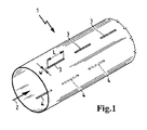
- FIG. 1 of the drawing which is not part of the invention shows a suction pipe 1 as an air flow conduit, for example, provided in the intake section for supplying the intake air 2 of an internal combustion engine which is not described herein in more detail.
- Said suction pipe 1 is provided with orifices 3 being integrated for absorbing the sound emission in order to be able to optimize those zones of the suction pipe 1 serving as sound absorber.
- the slit-like orifices 3 have a predetermined length L and/or an orifice area amounting, for example, to 320 mm 2 , with the selected width W ranging between 0.5 mm and 1.7 mm.
- the respective absorption ratios for the different widths W are shown in Figure 2, wherein curve 20 generates a width W of 1.7 mm, curve 21 a width W of 0.5 mm, and curve 22 a width W of 0.2 mm.
- Figure 1 shows that the slit-like orifices 4 are likewise arranged which are located on the opposite ends of the suction pipe 1 and across the flow direction.
- the curves 30 to 34 - as shown in Figure 3 - occur if the respective orifice areas of the slit-like orifices 3 and 4 provided on the opposite ends of the suction pipe 1 are unequal.
- the curves 30 to 31 indicate the frequency-dependent absorption behavior TL (dB), with the width W of the orifice areas ranging from 0.2 mm to 0.5 mm on both ends of suction pipe 1.
- the curves 32 to 33 indicates the frequency dependant adsorption behavior TL (dB) with the width W of 0.8mm and 1.7mm.
- the curve 34 indicates the reference level for a width W of 1.7mm.
- said arrangement turns out to be favorable in which the individual areas of the orifices 3 provided on one end of the flow conduit amount to 100 mm 2 and the orifices 4 provided on the respective other end of the conduit amount to 50 mm 2 .
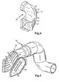
- Figure 4 shows an example for a suction pipe 40, with slit-like orifices 42 being provided in the curvature region 41 which are dimensioned according to the examples as described previously.
- Figure 5 shows an exemplified embodiment including a closable flap 50, which can be placed over the slit-like orifices 51 in the curvature region 52, thus forming a resonator chamber that even supports the sound-absorbing measures mentioned above.
- the flap 50 is additionally provided with slits 53.
Landscapes
- Engineering & Computer Science (AREA)
- General Engineering & Computer Science (AREA)
- Mechanical Engineering (AREA)
- Chemical & Material Sciences (AREA)
- Combustion & Propulsion (AREA)
- Exhaust Silencers (AREA)
- Soundproofing, Sound Blocking, And Sound Damping (AREA)
Description
- The invention refers to a sound absorber suitable for an air-flow conduit, as it is, for example, available in the intake section of an internal combustion engine of vehicles according to the preamble to the principal claim.
- It is already known from
FR 2 814 778 A1 - In addition, the state of technology further discloses that - for those sound emissions especially interfering during the operation of an internal combustion engine - the dimensions of both the length and width of said orifices are applicable in a successful way.
-
EP 1 170 499 A1 - Despite these known approaches to reduce the sound emissions, which are already known per se, it is, however, often very important for individual applications to attenuate a very specific frequency range to a required extent so that the efficiency of the sound absorber will be optimized according to the conditions of the internal combustion engine and the vehicle. It is often very difficult to dimension the geometry and the position of the orifices that are required for each specific case, often leading to unforeseeable results.
- The object underlying the present invention is to develop a sound absorber of that kind mentioned previously in such a way that the absorption behavior of the sound absorber can be influenced optimally and in dependency upon the sound frequency.
- The invention is based on a sound absorber suitable for an air-flow conduit wherein the sound-bearing conduit is provided with orifices in specific areas, wherein the length of said orifices in flow direction and the width thereof are dimensioned according to a predetermined size. In an advantageous manner, the present invention allows to improve the specific absorption characteristics in that - based on a predetermined orifice area of the slit-like orifices - a ratio of the orifices' length to the width thereof is selected in dependency upon a specific frequency range of sound emission to be absorbed.
- It is particularly advantageous that each of the slit-like orifices has an orifice area in the range of 320 mm2, with a selected width ranging between 0.5 mm and 1.7 mm. Through this increasing ratio of length to width of the slit-like orifices according to this invention compared to the conventional orifice areas, it surprisingly could be managed to achieve a very good absorption behavior of the conduit at a frequency larger than 400 Hz.
- Exemplified embodiments of the sound absorber according to the present invention are shown in the figures of the drawings, in which:
- Fig. 1 shows a sectional illustration of a suction pipe suitable for the intake air of an internal combustion engine comprising slit-like orifices,
- Fig. 2 shows a diagram of the frequency-dependent absorption in case of slit-like orifices being of different length/width ratios,
- Fig. 3 shows a diagram of the frequency-dependent absorption in case of slit-like orifices having different orifice areas on the opposite ends of the flow conduit,
- Fig. 4 shows an application of slit-like orifices provided in the curvature region of a suction pipe, and
- Fig. 5 is an exemplified embodiment with a resonator chamber being formed by a closable flap arranged over the slit-like orifices.
- Figure 1 of the drawing which is not part of the invention shows a
suction pipe 1 as an air flow conduit, for example, provided in the intake section for supplying theintake air 2 of an internal combustion engine which is not described herein in more detail. Saidsuction pipe 1 is provided withorifices 3 being integrated for absorbing the sound emission in order to be able to optimize those zones of thesuction pipe 1 serving as sound absorber. - According to a first embodiment, the slit-
like orifices 3 have a predetermined length L and/or an orifice area amounting, for example, to 320 mm2, with the selected width W ranging between 0.5 mm and 1.7 mm. The respective absorption ratios for the different widths W are shown in Figure 2, whereincurve 20 generates a width W of 1.7 mm, curve 21 a width W of 0.5 mm, and curve 22 a width W of 0.2 mm. - As shown by the curves illustrated in Figure 2, by way of this exemplified embodiment and in providing a length/width ratios L/W for the slit-
like orifices 2 in accordance with the invention, it is possible to achieve an increasing absorption behavior TL (dB) within thesuction pipe 1 for a frequency larger than 400 Hz. - In addition, Figure 1 shows that the slit-
like orifices 4 are likewise arranged which are located on the opposite ends of thesuction pipe 1 and across the flow direction. - The
curves 30 to 34 - as shown in Figure 3 - occur if the respective orifice areas of the slit-like orifices suction pipe 1 are unequal. Thecurves 30 to 31 indicate the frequency-dependent absorption behavior TL (dB), with the width W of the orifice areas ranging from 0.2 mm to 0.5 mm on both ends ofsuction pipe 1. Thecurves 32 to 33 indicates the frequency dependant adsorption behavior TL (dB) with the width W of 0.8mm and 1.7mm. Thecurve 34 indicates the reference level for a width W of 1.7mm. Especially for absorbing the sound emission below 500 Hz, said arrangement turns out to be favorable in which the individual areas of theorifices 3 provided on one end of the flow conduit amount to 100 mm2 and theorifices 4 provided on the respective other end of the conduit amount to 50 mm2. - Figure 4 shows an example for a
suction pipe 40, with slit-like orifices 42 being provided in thecurvature region 41 which are dimensioned according to the examples as described previously. - Figure 5 shows an exemplified embodiment including a
closable flap 50, which can be placed over the slit-like orifices 51 in thecurvature region 52, thus forming a resonator chamber that even supports the sound-absorbing measures mentioned above. To further improve the sound absorption, theflap 50 is additionally provided withslits 53.
Claims (3)
- Sound absorber comprising an air-flow conduit, wherein- specific zones of the sound-bearing air-flow conduit are provided with slit-like orifices (42, 51), wherein the length thereof in flow direction and the width thereof are dimensioned according to a predetermined size,- based on a predetermined orifice area of the slit-like orifices (42, 51), a ratio of the orifices' length (L) to the width (W) thereof is selected in dependency upon a specific frequency range of sound emission to be absorbed, characterized in that,- the slit-like orifices (42) are provided in a suction pipe (40, 54) of an internal combustion engine serving as the sound-bearing conduit in the curvature region (41) and- a closable flap (50) is provided on the suction pipe (54) of an internal combustion engine serving as the sound-bearing conduit, wherein said flap (50) can be placed over the slit-like orifices (51) provided in the curvature region (52).
- Sound absorber according to patent claim 1, characterized in that- each of the slit-like orifices (42, 51) has an orifice area amounting to 320 mm2, and whereas the selected width thereof ranges between 0.5 mm and 1.7 mm.
- Sound absorber according to patent claims 1 or 2, characterized in that- the closable flap (50) is provided with slit-like orifices (53).
Priority Applications (3)
| Application Number | Priority Date | Filing Date | Title |
|---|---|---|---|
| DE2003617802 DE60317802T2 (en) | 2003-12-11 | 2003-12-11 | silencer |
| EP20030104654 EP1541856B1 (en) | 2003-12-11 | 2003-12-11 | Sound adsorber suitable for air-flow conduits |
| ES03104654T ES2295516T3 (en) | 2003-12-11 | 2003-12-11 | SOUND ABSORBENT FOR AIR CURRENT DUCTS. |
Applications Claiming Priority (1)
| Application Number | Priority Date | Filing Date | Title |
|---|---|---|---|
| EP20030104654 EP1541856B1 (en) | 2003-12-11 | 2003-12-11 | Sound adsorber suitable for air-flow conduits |
Publications (2)
| Publication Number | Publication Date |
|---|---|
| EP1541856A1 EP1541856A1 (en) | 2005-06-15 |
| EP1541856B1 true EP1541856B1 (en) | 2007-11-28 |
Family
ID=34486384
Family Applications (1)
| Application Number | Title | Priority Date | Filing Date |
|---|---|---|---|
| EP20030104654 Expired - Lifetime EP1541856B1 (en) | 2003-12-11 | 2003-12-11 | Sound adsorber suitable for air-flow conduits |
Country Status (3)
| Country | Link |
|---|---|
| EP (1) | EP1541856B1 (en) |
| DE (1) | DE60317802T2 (en) |
| ES (1) | ES2295516T3 (en) |
Families Citing this family (3)
| Publication number | Priority date | Publication date | Assignee | Title |
|---|---|---|---|---|
| JP5987425B2 (en) | 2012-04-05 | 2016-09-07 | スズキ株式会社 | Intake device for internal combustion engine |
| DE102013215636A1 (en) | 2013-08-08 | 2015-02-12 | Mahle International Gmbh | Silencer |
| DE102015200966A1 (en) | 2015-01-21 | 2016-07-21 | DIL Deutsches Institut für Lebensmitteltechnik e.V. | Silencer for suction pads |
Family Cites Families (6)
| Publication number | Priority date | Publication date | Assignee | Title |
|---|---|---|---|---|
| DE19504223A1 (en) * | 1995-02-09 | 1996-08-14 | Volkswagen Ag | Intake silencer for internal combustion engine |
| SE506188C2 (en) * | 1996-01-25 | 1997-11-17 | Dale Edward Knipstein | Sound absorbing element and method for making this element and use of the element |
| DE19750102A1 (en) * | 1997-11-12 | 1999-06-02 | Stankiewicz Gmbh | Gas-flowed line with sound absorption effect |
| FR2788833B1 (en) * | 1999-01-22 | 2001-03-16 | Mecaplast Sam | AIR NOISE REDUCTION DEVICE, MANUFACTURING METHOD AND USES OF SUCH A DEVICE |
| GB2364352A (en) | 2000-07-03 | 2002-01-23 | Draftex Ind Ltd | Noise reduction in air conduits; making perforated conduits |
| FR2814778B1 (en) | 2000-09-29 | 2003-01-10 | Peugeot Citroen Automobiles Sa | CONDUIT FOR THE TRANSPORT OF GASEOUS FLUID AND AIR INTAKE DEVICE FOR AN INTERNAL COMBUSTION ENGINE COMPRISING SUCH A CONDUIT |
-
2003
- 2003-12-11 EP EP20030104654 patent/EP1541856B1/en not_active Expired - Lifetime
- 2003-12-11 ES ES03104654T patent/ES2295516T3/en not_active Expired - Lifetime
- 2003-12-11 DE DE2003617802 patent/DE60317802T2/en not_active Expired - Lifetime
Also Published As
| Publication number | Publication date |
|---|---|
| DE60317802D1 (en) | 2008-01-10 |
| ES2295516T3 (en) | 2008-04-16 |
| EP1541856A1 (en) | 2005-06-15 |
| DE60317802T2 (en) | 2008-10-30 |
Similar Documents
| Publication | Publication Date | Title |
|---|---|---|
| US8166775B2 (en) | Noise attenuating device for a heating-ventilation-cooling system of a motor vehicle | |
| JP3562235B2 (en) | Intake noise reduction device for internal combustion engine | |
| US7086498B2 (en) | Noise attenuation device for a vehicle exhaust system | |
| EP2907997B1 (en) | Resonator for vehicle | |
| US20050252716A1 (en) | Electronically controlled dual chamber variable resonator | |
| US7249652B2 (en) | Fluid guideline, especially in the form of a tube for taking up untreated air in an air filter of a motor vehicle | |
| EP3438443B1 (en) | Noise reduction device for vehicle | |
| US20080230307A1 (en) | Muffle duct | |
| US20110083924A1 (en) | Muffler for vehicle | |
| CN209838498U (en) | Exhaust system, resonator and muffler system for vehicle | |
| CA2484784C (en) | Exhaust muffler for internal combustion engines | |
| JP4166593B2 (en) | Silencer | |
| KR102532322B1 (en) | Muffler for vehicle | |
| EP1541856A1 (en) | Sound adsorber suitable for air-flow conduits | |
| US5246473A (en) | High performance exhaust muffler | |
| US4596306A (en) | Exhaust silencing system | |
| US10066589B2 (en) | Independent intake runner resonator system | |
| KR101280597B1 (en) | A device for damping of sound in a pipe | |
| CN202294164U (en) | Air passage of passenger car air conditioner air return fan and passenger car with same | |
| KR20210051829A (en) | Muffler for performing the sporty sound used for a car | |
| EP1253312B1 (en) | Low-noise integrated air-filtering device | |
| JP2011017291A (en) | Air suction device | |
| JPH078516U (en) | Resonant submuffler | |
| US20050072627A1 (en) | Noise reduction device having walls therein | |
| RU2737014C1 (en) | Internal combustion engine with an air inlet system |
Legal Events
| Date | Code | Title | Description |
|---|---|---|---|
| PUAI | Public reference made under article 153(3) epc to a published international application that has entered the european phase |
Free format text: ORIGINAL CODE: 0009012 |
|
| AK | Designated contracting states |
Kind code of ref document: A1 Designated state(s): AT BE BG CH CY CZ DE DK EE ES FI FR GB GR HU IE IT LI LU MC NL PT RO SE SI SK TR |
|
| AX | Request for extension of the european patent |
Extension state: AL LT LV MK |
|
| 17P | Request for examination filed |
Effective date: 20050708 |
|
| AKX | Designation fees paid |
Designated state(s): AT BE BG CH CY CZ DE DK EE ES FI FR GB GR HU IE IT LI LU MC NL PT RO SE SI SK TR |
|
| 17Q | First examination report despatched |
Effective date: 20051017 |
|
| GRAP | Despatch of communication of intention to grant a patent |
Free format text: ORIGINAL CODE: EPIDOSNIGR1 |
|
| GRAS | Grant fee paid |
Free format text: ORIGINAL CODE: EPIDOSNIGR3 |
|
| GRAA | (expected) grant |
Free format text: ORIGINAL CODE: 0009210 |
|
| AK | Designated contracting states |
Kind code of ref document: B1 Designated state(s): AT BE BG CH CY CZ DE DK EE ES FI FR GB GR HU IE IT LI LU MC NL PT RO SE SI SK TR |
|
| REG | Reference to a national code |
Ref country code: GB Ref legal event code: FG4D |
|
| REG | Reference to a national code |
Ref country code: IE Ref legal event code: FG4D |
|
| REG | Reference to a national code |
Ref country code: CH Ref legal event code: EP |
|
| REF | Corresponds to: |
Ref document number: 60317802 Country of ref document: DE Date of ref document: 20080110 Kind code of ref document: P |
|
| REG | Reference to a national code |
Ref country code: ES Ref legal event code: FG2A Ref document number: 2295516 Country of ref document: ES Kind code of ref document: T3 |
|
| PG25 | Lapsed in a contracting state [announced via postgrant information from national office to epo] |
Ref country code: NL Free format text: LAPSE BECAUSE OF FAILURE TO SUBMIT A TRANSLATION OF THE DESCRIPTION OR TO PAY THE FEE WITHIN THE PRESCRIBED TIME-LIMIT Effective date: 20071128 Ref country code: SE Free format text: LAPSE BECAUSE OF FAILURE TO SUBMIT A TRANSLATION OF THE DESCRIPTION OR TO PAY THE FEE WITHIN THE PRESCRIBED TIME-LIMIT Effective date: 20080228 Ref country code: CH Free format text: LAPSE BECAUSE OF FAILURE TO SUBMIT A TRANSLATION OF THE DESCRIPTION OR TO PAY THE FEE WITHIN THE PRESCRIBED TIME-LIMIT Effective date: 20071128 Ref country code: LI Free format text: LAPSE BECAUSE OF FAILURE TO SUBMIT A TRANSLATION OF THE DESCRIPTION OR TO PAY THE FEE WITHIN THE PRESCRIBED TIME-LIMIT Effective date: 20071128 |
|
| NLV1 | Nl: lapsed or annulled due to failure to fulfill the requirements of art. 29p and 29m of the patents act | ||
| PG25 | Lapsed in a contracting state [announced via postgrant information from national office to epo] |
Ref country code: SI Free format text: LAPSE BECAUSE OF FAILURE TO SUBMIT A TRANSLATION OF THE DESCRIPTION OR TO PAY THE FEE WITHIN THE PRESCRIBED TIME-LIMIT Effective date: 20071128 Ref country code: BG Free format text: LAPSE BECAUSE OF FAILURE TO SUBMIT A TRANSLATION OF THE DESCRIPTION OR TO PAY THE FEE WITHIN THE PRESCRIBED TIME-LIMIT Effective date: 20080228 Ref country code: FI Free format text: LAPSE BECAUSE OF FAILURE TO SUBMIT A TRANSLATION OF THE DESCRIPTION OR TO PAY THE FEE WITHIN THE PRESCRIBED TIME-LIMIT Effective date: 20071128 |
|
| REG | Reference to a national code |
Ref country code: CH Ref legal event code: PL |
|
| PG25 | Lapsed in a contracting state [announced via postgrant information from national office to epo] |
Ref country code: AT Free format text: LAPSE BECAUSE OF FAILURE TO SUBMIT A TRANSLATION OF THE DESCRIPTION OR TO PAY THE FEE WITHIN THE PRESCRIBED TIME-LIMIT Effective date: 20071128 |
|
| PG25 | Lapsed in a contracting state [announced via postgrant information from national office to epo] |
Ref country code: CZ Free format text: LAPSE BECAUSE OF FAILURE TO SUBMIT A TRANSLATION OF THE DESCRIPTION OR TO PAY THE FEE WITHIN THE PRESCRIBED TIME-LIMIT Effective date: 20071128 Ref country code: MC Free format text: LAPSE BECAUSE OF NON-PAYMENT OF DUE FEES Effective date: 20071231 Ref country code: DK Free format text: LAPSE BECAUSE OF FAILURE TO SUBMIT A TRANSLATION OF THE DESCRIPTION OR TO PAY THE FEE WITHIN THE PRESCRIBED TIME-LIMIT Effective date: 20071128 |
|
| ET | Fr: translation filed | ||
| PG25 | Lapsed in a contracting state [announced via postgrant information from national office to epo] |
Ref country code: RO Free format text: LAPSE BECAUSE OF FAILURE TO SUBMIT A TRANSLATION OF THE DESCRIPTION OR TO PAY THE FEE WITHIN THE PRESCRIBED TIME-LIMIT Effective date: 20071128 Ref country code: BE Free format text: LAPSE BECAUSE OF FAILURE TO SUBMIT A TRANSLATION OF THE DESCRIPTION OR TO PAY THE FEE WITHIN THE PRESCRIBED TIME-LIMIT Effective date: 20071128 Ref country code: SK Free format text: LAPSE BECAUSE OF FAILURE TO SUBMIT A TRANSLATION OF THE DESCRIPTION OR TO PAY THE FEE WITHIN THE PRESCRIBED TIME-LIMIT Effective date: 20071128 |
|
| PG25 | Lapsed in a contracting state [announced via postgrant information from national office to epo] |
Ref country code: PT Free format text: LAPSE BECAUSE OF FAILURE TO SUBMIT A TRANSLATION OF THE DESCRIPTION OR TO PAY THE FEE WITHIN THE PRESCRIBED TIME-LIMIT Effective date: 20080428 |
|
| PLBE | No opposition filed within time limit |
Free format text: ORIGINAL CODE: 0009261 |
|
| STAA | Information on the status of an ep patent application or granted ep patent |
Free format text: STATUS: NO OPPOSITION FILED WITHIN TIME LIMIT |
|
| GBPC | Gb: european patent ceased through non-payment of renewal fee |
Effective date: 20080228 |
|
| PG25 | Lapsed in a contracting state [announced via postgrant information from national office to epo] |
Ref country code: IE Free format text: LAPSE BECAUSE OF NON-PAYMENT OF DUE FEES Effective date: 20071211 |
|
| 26N | No opposition filed |
Effective date: 20080829 |
|
| PG25 | Lapsed in a contracting state [announced via postgrant information from national office to epo] |
Ref country code: GR Free format text: LAPSE BECAUSE OF FAILURE TO SUBMIT A TRANSLATION OF THE DESCRIPTION OR TO PAY THE FEE WITHIN THE PRESCRIBED TIME-LIMIT Effective date: 20080229 Ref country code: EE Free format text: LAPSE BECAUSE OF FAILURE TO SUBMIT A TRANSLATION OF THE DESCRIPTION OR TO PAY THE FEE WITHIN THE PRESCRIBED TIME-LIMIT Effective date: 20071128 |
|
| PG25 | Lapsed in a contracting state [announced via postgrant information from national office to epo] |
Ref country code: GB Free format text: LAPSE BECAUSE OF NON-PAYMENT OF DUE FEES Effective date: 20080228 |
|
| PG25 | Lapsed in a contracting state [announced via postgrant information from national office to epo] |
Ref country code: CY Free format text: LAPSE BECAUSE OF FAILURE TO SUBMIT A TRANSLATION OF THE DESCRIPTION OR TO PAY THE FEE WITHIN THE PRESCRIBED TIME-LIMIT Effective date: 20071128 |
|
| PG25 | Lapsed in a contracting state [announced via postgrant information from national office to epo] |
Ref country code: LU Free format text: LAPSE BECAUSE OF NON-PAYMENT OF DUE FEES Effective date: 20071211 |
|
| PG25 | Lapsed in a contracting state [announced via postgrant information from national office to epo] |
Ref country code: HU Free format text: LAPSE BECAUSE OF FAILURE TO SUBMIT A TRANSLATION OF THE DESCRIPTION OR TO PAY THE FEE WITHIN THE PRESCRIBED TIME-LIMIT Effective date: 20080529 Ref country code: TR Free format text: LAPSE BECAUSE OF FAILURE TO SUBMIT A TRANSLATION OF THE DESCRIPTION OR TO PAY THE FEE WITHIN THE PRESCRIBED TIME-LIMIT Effective date: 20071128 |
|
| PG25 | Lapsed in a contracting state [announced via postgrant information from national office to epo] |
Ref country code: FR Free format text: LAPSE BECAUSE OF NON-PAYMENT OF DUE FEES Effective date: 20091231 |
|
| PGFP | Annual fee paid to national office [announced via postgrant information from national office to epo] |
Ref country code: IT Payment date: 20121219 Year of fee payment: 10 |
|
| PGFP | Annual fee paid to national office [announced via postgrant information from national office to epo] |
Ref country code: ES Payment date: 20121226 Year of fee payment: 10 Ref country code: FR Payment date: 20130130 Year of fee payment: 10 Ref country code: DE Payment date: 20121220 Year of fee payment: 10 |
|
| REG | Reference to a national code |
Ref country code: DE Ref legal event code: R119 Ref document number: 60317802 Country of ref document: DE |
|
| REG | Reference to a national code |
Ref country code: DE Ref legal event code: R119 Ref document number: 60317802 Country of ref document: DE Effective date: 20140701 |
|
| REG | Reference to a national code |
Ref country code: FR Ref legal event code: ST Effective date: 20140829 |
|
| PG25 | Lapsed in a contracting state [announced via postgrant information from national office to epo] |
Ref country code: DE Free format text: LAPSE BECAUSE OF NON-PAYMENT OF DUE FEES Effective date: 20140701 |
|
| PG25 | Lapsed in a contracting state [announced via postgrant information from national office to epo] |
Ref country code: FR Free format text: LAPSE BECAUSE OF NON-PAYMENT OF DUE FEES Effective date: 20131231 |
|
| REG | Reference to a national code |
Ref country code: ES Ref legal event code: FD2A Effective date: 20150709 |
|
| PG25 | Lapsed in a contracting state [announced via postgrant information from national office to epo] |
Ref country code: ES Free format text: LAPSE BECAUSE OF NON-PAYMENT OF DUE FEES Effective date: 20131212 |
|
| PG25 | Lapsed in a contracting state [announced via postgrant information from national office to epo] |
Ref country code: IT Free format text: LAPSE BECAUSE OF NON-PAYMENT OF DUE FEES Effective date: 20131231 |
|
| PG25 | Lapsed in a contracting state [announced via postgrant information from national office to epo] |
Ref country code: IT Free format text: LAPSE BECAUSE OF NON-PAYMENT OF DUE FEES Effective date: 20131211 |