EP1541773A2 - Wheel-type construction machine - Google Patents
Wheel-type construction machine Download PDFInfo
- Publication number
- EP1541773A2 EP1541773A2 EP04029058A EP04029058A EP1541773A2 EP 1541773 A2 EP1541773 A2 EP 1541773A2 EP 04029058 A EP04029058 A EP 04029058A EP 04029058 A EP04029058 A EP 04029058A EP 1541773 A2 EP1541773 A2 EP 1541773A2
- Authority
- EP
- European Patent Office
- Prior art keywords
- tilt angle
- vehicle
- hydraulic
- hydraulic suspension
- maximum tolerable
- Prior art date
- Legal status (The legal status is an assumption and is not a legal conclusion. Google has not performed a legal analysis and makes no representation as to the accuracy of the status listed.)
- Withdrawn
Links
- 238000010276 construction Methods 0.000 title claims description 21
- 239000000725 suspension Substances 0.000 claims abstract description 129
- 239000010720 hydraulic oil Substances 0.000 claims abstract description 55
- 238000001514 detection method Methods 0.000 claims description 33
- 238000005096 rolling process Methods 0.000 claims description 12
- 230000001771 impaired effect Effects 0.000 abstract description 8
- 238000012545 processing Methods 0.000 description 21
- 239000007789 gas Substances 0.000 description 17
- 238000000034 method Methods 0.000 description 17
- 230000005484 gravity Effects 0.000 description 8
- 230000003247 decreasing effect Effects 0.000 description 6
- 230000002265 prevention Effects 0.000 description 6
- 230000035939 shock Effects 0.000 description 5
- 230000000694 effects Effects 0.000 description 3
- IJGRMHOSHXDMSA-UHFFFAOYSA-N Atomic nitrogen Chemical compound N#N IJGRMHOSHXDMSA-UHFFFAOYSA-N 0.000 description 2
- 239000006096 absorbing agent Substances 0.000 description 2
- 230000001133 acceleration Effects 0.000 description 2
- 238000013016 damping Methods 0.000 description 2
- 230000007423 decrease Effects 0.000 description 2
- 238000010586 diagram Methods 0.000 description 2
- 229910001873 dinitrogen Inorganic materials 0.000 description 2
- 239000003921 oil Substances 0.000 description 2
- 230000006835 compression Effects 0.000 description 1
- 238000007906 compression Methods 0.000 description 1
Images





Classifications
-
- E—FIXED CONSTRUCTIONS
- E02—HYDRAULIC ENGINEERING; FOUNDATIONS; SOIL SHIFTING
- E02F—DREDGING; SOIL-SHIFTING
- E02F9/00—Component parts of dredgers or soil-shifting machines, not restricted to one of the kinds covered by groups E02F3/00 - E02F7/00
- E02F9/20—Drives; Control devices
- E02F9/22—Hydraulic or pneumatic drives
- E02F9/2257—Vehicle levelling or suspension systems
-
- E—FIXED CONSTRUCTIONS
- E02—HYDRAULIC ENGINEERING; FOUNDATIONS; SOIL SHIFTING
- E02F—DREDGING; SOIL-SHIFTING
- E02F9/00—Component parts of dredgers or soil-shifting machines, not restricted to one of the kinds covered by groups E02F3/00 - E02F7/00
- E02F9/20—Drives; Control devices
- E02F9/22—Hydraulic or pneumatic drives
- E02F9/2217—Hydraulic or pneumatic drives with energy recovery arrangements, e.g. using accumulators, flywheels
-
- E—FIXED CONSTRUCTIONS
- E02—HYDRAULIC ENGINEERING; FOUNDATIONS; SOIL SHIFTING
- E02F—DREDGING; SOIL-SHIFTING
- E02F9/00—Component parts of dredgers or soil-shifting machines, not restricted to one of the kinds covered by groups E02F3/00 - E02F7/00
- E02F9/20—Drives; Control devices
- E02F9/22—Hydraulic or pneumatic drives
- E02F9/2221—Control of flow rate; Load sensing arrangements
- E02F9/2225—Control of flow rate; Load sensing arrangements using pressure-compensating valves
- E02F9/2228—Control of flow rate; Load sensing arrangements using pressure-compensating valves including an electronic controller
-
- E—FIXED CONSTRUCTIONS
- E02—HYDRAULIC ENGINEERING; FOUNDATIONS; SOIL SHIFTING
- E02F—DREDGING; SOIL-SHIFTING
- E02F9/00—Component parts of dredgers or soil-shifting machines, not restricted to one of the kinds covered by groups E02F3/00 - E02F7/00
- E02F9/24—Safety devices, e.g. for preventing overload
Definitions
- the present invention relates to a wheel-type construction machine, such as a wheel-type excavator, and particularly, to a wheel-type construction machine which is loaded with an apparatus for preventing the vehicle body from being overturned in the rolling directions.
- a wheel-type construction machine 1 when traveling on a public road, is legally requested by a rule in Japan to be not overturned in the rolling directions, i.e., in the rightward or leftward direction of the vehicle body on an inclined road 90 of the maximum tilt angle (for example, 30 degree).
- Some of wheel-type construction machines are provided with a hydraulic suspension for each of the wheels.
- this problem has been alleviated by providing, in a pipe line 33 between a hydraulic oil chamber 32 for a hydraulic suspension cylinder 21 and an accumulator 34, a suspension lock relief valve 45 which is set at the pressure same as or higher than the pressure applied to the hydraulic suspension cylinder 21 on an inclined road 90 which inclination angle is equal to the maximum tilt angle.
- the suspension locking relief valve 45 is shifted to the open position.
- the pressure in the hydraulic oil chamber 32 of the hydraulic suspension cylinder 21 is increased, the high-pressure gas in the gas chamber 36 in the accumulator 34, which is connected to the hydraulic oil chamber 32, is compressed, thereby generating a repulsive force due to the elasticity of the gas.
- Japanese patent application publication No. 5-345509 discloses an invention which determines the.increase in the amount of rolling in the turning based on the vehicle speed and the steering angle, and decreases the tilt of a vehicle toward the outside thereof resulting from the centrifugal force by increasing the damping force of the shock absorber according to the determination.
- Japanese patent application publication No. 2000-302063 discloses an invention which locks the differential gear in the rear body for preventing the overturning of the rear body when the tilt angle for the rear body of an articulate vehicle in the rightward or leftward direction exceeds the overturning threshold value.
- Japanese patent application publication No. 5-139132 discloses an invention which provides an acceleration sensor for a hydraulic cylinder of a wheel-type excavator, and controls the inflow and outflow of hydraulic oil for hydraulic cylinder for suppressing the vertical jolt of the body based on the result of detection by the acceleration sensor in cargo work.
- Japanese patent application publication No. 2000-507648 discloses an invention which calculates the effective center of gravity of the vehicle for indicating it on the display, based on the results of detection by a plurality of tilt sensors provided for the vehicle.
- Japanese patent application publication No. 7-266826 discloses an invention which switches over the damping force of the shock absorber to suppress the occurrence of nosedive and squat of the body according to the tilt angle detected by the tilt angle sensor.
- Japanese patent application publication No. 2001-334816 discloses an invention for a vehicle structured such that the frame swings with respect to the axle, which restricts or permits the swing of the frame during the turning for allowing the vehicle to be stably turned, based on the frame swing angle, the vehicle speed, the position of center of gravity of the load, the steering angle, the steering angular velocity, and the like.
- the present invention has been made in view of the above circumstances and provides a solution to the problem of preventing the overturning on an inclined road which inclination angle is equal to or smaller than the maximum tolerable tilt angle without impairing the function of the hydraulic suspensions.
- Japanese patent application publication No. 5-345509 provides an invention which solves the problem of suppressing the increase in the amount of rolling in the turning, thus differing from the present invention which gives a solution to the problem of preventing the overturning on an inclined road which inclination angle is equal to or smaller than the maximum tilt angle.
- Japanese patent application publication No. 2000-302063 provides an invention which locks the differential gear for preventing the overturning of the rear body, thus differing from the present invention which presupposes a vehicle provided with hydraulic suspensions.
- Japanese patent application publication No. 5-139132 provides an invention which solves the problem of suppressing the vertical jolt of the body, thus differing from the present invention which gives a solution to the problem of preventing the overturning on an inclined road which inclination angle is equal to or smaller than the maximum tilt angle.
- Japanese patent application publication No. 2001-507648 provides an invention which relates only to calculating the effective center of gravity of the vehicle for indicating it on the display, thus differing from the present invention which controls the hydraulic suspensions for prevention of the overturning.
- Japanese patent application publication No. 7-266826 provides an invention which solves the problem of suppressing the occurrence of nosedive and squat of the body, and thus differs from the present invention which controls the hydraulic suspensions for prevention of the overturning.
- Japanese patent application publication No. 2001-334816 provides an invention which solves the problem of turning the vehicle with stability, thus differing from the present invention which controls the hydraulic suspensions for prevention of the overturning.
- a first aspect of the present invention provides a wheel-type construction machine 1 having a body 2 that is connected to wheels 11, 12 through hydraulic suspension cylinders 21, 22, comprising a tilt angle sensor 3 for detecting a tilt angle in rolling directions of the body 2; a vehicle speed sensor 4 for detecting a vehicle speed; and a controller 5 for performing a control of shutting off inflow and outflow of a hydraulic oil for the hydraulic suspension cylinders 21, 22 when the tilt angle detected by the tilt angle sensor 3 exceeds a maximum tolerable tilt angle based on detection values given by the tilt angle sensor 3 and the vehicle speed sensor 4.
- a second aspect of the present invention provides the wheel-type construction machine of the first aspect of the present invention, wherein the maximum tolerable tilt angle is determined according to a vehicle speed detected by the vehicle speed sensor 4.
- a third aspect of the present invention provides a wheel-type construction machine 1 having a body 2 that is connected to wheels 11, 12 through hydraulic suspension cylinders 21, 22, comprising: a tilt angle sensor 3 for detecting a tilt angle in rolling directions of the body 2; vehicle height adjusting means 33, 34, 51, 52, 55 for adjusting a vehicle height by controlling inflow and outflow of a hydraulic oil for the hydraulic suspension cylinders 21, 22; and controlling means 5 for controlling the vehicle height adjusting means 33, 34, 51, 52, 55 to bring the tilt angle of the body 2 to being equal to or smaller than the maximum tolerable tilt angle when the tilt angle detected by the tilt angle sensor 3 exceeds a maximum tolerable tilt angle.
- a fourth aspect of the present invention provides a wheel-type construction machine 1 with which a body 2 is connected to wheels 11, 12 through hydraulic suspension cylinders 21, 22, comprising a tilt angle sensor 3 for detecting a tilt angle in the rolling directions ofthe body 2; vehicle height adjusting means 33, 34, 51, 52, 55 for adjusting a vehicle height by controlling inflow and outflow of a hydraulic oil for the hydraulic suspension cylinders 21, 22; and controlling means 5 for controlling the vehicle height adjusting means 33, 34, 51, 52, 55 to bring the body 2 close to the horizontal posture according to the tilt angle detected by the tilt angle sensor 3.
- the "hydraulic suspension locked state” is given based on the detection values given by the tilt angle sensor 3 and the vehicle speed sensor 4 regardless of the tilt angle; when the vehicle 1 is traveling, and the tilt angle is equal to or smaller than the maximum tolerable tilt angle ⁇ m, the "hydraulic suspension operating state” is given; and when the vehicle 1 is traveling, and the tilt angle exceeds the maximum tolerable tilt angle ⁇ m, the "hydraulic suspension locked state” is given.
- the breadth of tolerable tilt angle when the vehicle is standing and travels at low speed is greater than that for the first invention 1 (steps 202 to 205).
- the vehicle height adjusting means 33, 34, 51, 52, 55 is controlled to adjust the vehicle height for bringing the tilt angle ⁇ for the body 2 to within the maximum tolerable tilt angle ⁇ m (steps 702 to 705).
- the vehicle height adjusting means 33, 34, 51, 52, 55 is controlled to adjust the vehicle height, according to the tilt angle ⁇ , for bringing the tilt angle ⁇ for the body 2 closer to horizontal posture until the body 2 is in the horizontal posture (the tilt angle being zero) or in a substantially horizontal posture (steps 502 to 505).
- FIG. 2 is a side view of a vehicle employed in embodiments by way of example, which indicates the locations where respective sensors and a controller are disposed.
- a wheel-type excavator 1 comprising two axles and four wheels is adopted as an example of a vehicle.
- the body 2 On the front side of a body 2 of the wheel-type excavator 1, left-hand and right-hand wheels 11, 12 are provided. Also on the rear side of the body 2, left-hand and right-hand wheels 13, 14 are provided. To the body 2, a work machine 6 is connected.
- the body 2 essentially consists of a base carrier 2b to which the wheels are mounted, and a rotating superstructure 2a on which a cabin 2c is loaded and with which the work machine 6 is connected.
- a tilt angle sensor 3 for detecting the tilt angle ⁇ in the rightward or leftward direction, i.e., the rolling directions of the body 2.
- the wheels 11 to 14 are provided with a vehicle speed sensor 4 which detects the vehicle speed V by detecting the number of revolutions per unit time of the wheel.
- the vehicle speed sensor 4 may detects the vehicle speed other than by detecting the number of revolutions per unit time of the wheel. For example, the vehicle speed sensor 4 may detects the vehicle speed by detecting the speed relative to the ground.
- a controller 5 which inputs the detection signals from the respective sensors 3, 4, and outputs a control signal i.
- the body 2 is connected to the respective wheels 11 to 14 through a hydraulic suspension cylinder 21 to 24.
- a hydraulic suspension cylinder is provided for each of the wheels.
- a different configuration may be adopted in which only the front wheels are provided with a hydraulic suspension cylinder 21, 22.
- FIG. 3 shows a hydraulic circuit which controls the inflow and outflow of the hydraulic oil for the hydraulic suspension cylinders 21, 22 for the left-hand and right-hand front wheels 11, 12.
- the hydraulic suspension cylinder 21 essentially consists of an outer tube 30, and an inner tube 31 which slides in the outer tube 30.
- the inner tube 31 essentially consists of a piston 31a and a rod 31b connected to the piston 31a.
- the rod 31b of the inner tube 31 is connected to the body 2, and the outer tube 30 is connected to the wheel 11 through a suspension member, such as a link or an arm.
- the outer tube 30 and the piston 31a of the inner tube 31 forms a hydraulic oil chamber 32.
- the hydraulic oil chamber 32 is connected with a hydraulic oil chamber 35 of an accumulator 34 through a pipe line 33. In a gas chamber 36 of the accumulator 34, high-pressure air or high-pressure nitrogen gas, for example, is sealed.
- the hydraulic oil chamber 32 of the hydraulic suspension cylinder 21 is connected to another hydraulic oil chamber 32 of the hydraulic suspension cylinder.
- a control valve 40 is connected in the pipe line 33.
- the control valve 40 has two valve positions, i.e., a connecting position 40a and a disconnecting position 40b, and is operated in accordance with a control signal i (ON-OFF signal i) which is applied to an electromagnetic solenoid 40c.
- a control signal i from the controller 5 is applied to the electromagnetic solenoid 40c of the control valve 40.
- the control valve 40 is shifted to the connecting position 40a, while, when an OFF control signal i is applied to the electromagnetic solenoid 40c of the control valve 40, the control valve 40 shifts to the disconnecting position 40b.
- FIG. 4 illustrates the procedure for the processing performed in the embodiment 1, which is carried out by the controller 5.
- a detection signal from the tilt angle sensor 3 is inputted into the controller 5 (at step 101), and it is determined whether or not the current tilt angle for the body 2 is equal to or smaller than the maximum tolerable tilt angle ⁇ m (at step 102).
- the maximum tolerable tilt angle ⁇ m is defined as the maximum of the tilt angles at which the vehicle 1 will not be overturned even in the "hydraulic suspension operating state". In other words, when the tilt angle exceeds the maximum tolerable tilt angle ⁇ m, there is the possibility of the vehicle 1 being overturned, unless the vehicle 1 is in the "hydraulic suspension locked state".
- an ON control signal i for shifting the control valve 40 to the connecting position 40a is generated to give the "hydraulic suspension operating state" (at step 103), and this ON control signal i is applied to the electromagnetic solenoid 40c in the control valve 40.
- the control valve 40 is shifted to the connecting position 40a, thus the "hydraulic suspension operating state" being given (at step 104).
- an OFF control signal i for shifting the control valve 40 to the disconnecting position 40b is generated to give the "hydraulic suspension locked state" (at step 105), and this OFF control signal i is applied to the electromagnetic solenoid 40c in the control valve 40.
- the control valve 40 is shifted to the disconnecting position 40b, thus the "hydraulic suspension locked state” being given (at step 104).
- the hydraulic oil for the hydraulic suspension cylinders 21 to 24 for the wheels 11 to 14 flows freely. Therefore, as long as the vehicle 1 travels on a road having an inclination angle equal to or smaller than the maximum tolerable tilt angle ⁇ m, the shock imposed on the vehicle 1 by the irregularities of the road surface can be effectively absorbed while the vehicle 1 being prevented from being overturned.
- the current tilt angle ⁇ for the body 2 exceeds the maximum tolerable tilt angle ⁇ m, the inflow and outflow of the hydraulic oil for the hydraulic suspension cylinders 21 to 24 for the wheels 11 to 14 is locked.
- the vehicle 1 can be prevented from being overturned.
- overturning of the vehicle 1 on the inclined road having an inclination angle equal to or smaller than the maximum tilt angle can be prevented without the function of the hydraulic suspensions being impaired.
- the maximum tolerable tilt angle 0 m is fixed regardless of whether the vehicle 1 is traveling or standing, and therefore a vehicle speed sensor 4 is not necessarily required.
- a maximum tolerable tilt angle ⁇ m is fixed regardless of whether the vehicle 1 is traveling or standing.
- the value of the maximum tolerable tilt angle ⁇ m is changed with a change in vehicle speed.
- the body 2 will jolt due to shocks imposed on the vehicle 1 by the irregularities of the road surface or the like, resulting in that the position of the center of gravity of the vehicle 1 is likely to be changed. As a result, the vehicle 1 can more easily be overturned.
- the maximum tolerable tilt angle ⁇ m be set at a smaller value as the vehicle speed V is increased.
- the maximum tolerable tilt angle ⁇ m1 when the vehicle 1 is standing (the vehicle speed V is 0) and the maximum tolerable tilt angle ⁇ m2 ( ⁇ ⁇ m1) when the vehicle 1 is at a maximum speed (the vehicle speed V is at Vm) are previously determined. Then, these values are used to calculated the maximum tolerable tilt angle ⁇ m at a particular vehicle speed V by proportional distribution from the following equation (1).
- ⁇ m ⁇ m1 - V ⁇ ( ⁇ m1 - ⁇ m2)/(Vm - 0)
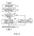
- FIG. 5 illustrates the procedure for processing in the embodiment 2 that is carried out by the controller 5.
- detection signals from the tilt angle sensor 3 and from the vehicle speed sensor 4 are inputted into the controller 5 (at step 201), and the maximum tolerable tilt angle ⁇ m for the current vehicle speed V is set based on the equation (1) (at step 202). Then, it is determined whether or not the current tilt angle ⁇ for the body 2 is equal to or smaller than the maximum tolerable tilt angle ⁇ m (at step 203).
- the same effects as those according to the embodiment 1 can be obtained.
- the maximum tolerable tilt angle ⁇ m changes according to the vehicle speed V, the range of maximum tolerable tilt angle when the vehicle is standing or travels at low speed becomes wider than that in the embodiment 1. As a result, the chance of the function of the hydraulic suspensions being impaired can be minimized.
- the "hydraulic suspension operating state” is given even when the vehicle 1 is standing, provided that the tilt angle is equal to or smaller than the maximum tolerable tilt angle ⁇ m.
- the “hydraulic suspension locked state” is given regardless of the tilt angle when the vehicle 1 is standing. If the vehicle is a construction machine, it is normally left standing while the work machine 6 is being operated for carrying out the work. During the work, the rotating superstructure 2b is turned or the work machine 6 is operated, which can result in the body 2 being jolted. Thus, when the vehicle 1 is positioned on an inclined road, there arises the possibility of being overturned due to the change in the position of the center of gravity of the vehicle 1. Thus, when the vehicle 1 is standing, it is preferable that the hydraulic suspensions be kept locked to prevent the overturning caused by the jolt as a result of the work.
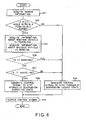
- FIG. 6 illustrates the procedure for processing in the embodiment 3 that is carried out by the controller 5.
- a detection signal from the tilt angle sensor 3 is inputted into the controller 5 (at step 301), and it is determined whether or not the current tilt angle ⁇ for the body 2 is equal to or smaller than the maximum tolerable tilt angle ⁇ m (at step 302).
- an OFF control signal i for shifting the control valve 40 to the disconnecting position 40b to give the "hydraulic suspension locked state” is generated (at step 303), and this OFF control signal i is applied to the electromagnetic solenoid 40c in the control valve 40.
- the control valve 40 is shifted to the disconnecting position 40b, the "hydraulic suspension locked state" being given (at step 304).
- step 302 when it has been determined that the current tilt angle ⁇ for the body 2 is equal to or smaller than the maximum tolerable tilt angle ⁇ m, information about whether the vehicle 1 is traveling, i.e., a detection signal from the vehicle speed sensor 4 is inputted into the controller 5 (at step 305), and based on the result of detection by the vehicle speed sensor 4, it is determined whether the vehicle 1 is traveling or standing (at step 307).
- a detection signal from the vehicle speed sensor 4 is inputted into the controller 5 (at step 305), and based on the result of detection by the vehicle speed sensor 4, it is determined whether the vehicle 1 is traveling or standing (at step 307).
- the program proceeds to the step 303, the "hydraulic suspension locked state" being given (at step 303, 304).
- an ON control signal i for shifting the control valve 40 to the connecting position 40a to give the "hydraulic suspension operating state” is generated (at step 308), and this ON control signal i is applied to the electromagnetic solenoid 40c in the control valve 40.
- the control valve 40 is shifted to the connecting position 40a, the "hydraulic suspension operating state” being given (at step 304).
- the "hydraulic suspension locked state” when the vehicle 1 is standing, the "hydraulic suspension locked state" is given regardless of the tilt angle; when the vehicle 1 is traveling, and the tilt angle is equal to or smaller than the maximum tolerable tilt angle ⁇ m, the “hydraulic suspension operating state” is given; and when the vehicle I is traveling, and the tilt angle exceeds the maximum tolerable tilt angle ⁇ m, the "hydraulic suspension locked state” is given.
- the processing in addition to information about whether the vehicle 1 is traveling (i.e., a detection signal from the vehicle speed sensor 4), information about whether the vehicle 1 is working is inputted into the controller 5 (at step 305).
- the information about whether the vehicle 1 is working can be acquired as, for example, a detection value given by the sensor which detects the operating position of the lever for operating the work machine 6, or a detection value given by the sensor which detects the hydraulic pressure in the hydraulic circuit for driving the work machine 6.
- step 305 whether the vehicle 1 is working is determined based on the detection signal from the sensor (at step 306).
- step 306 when it has been determined that the vehicle 1 is currently working, the program proceeds to the step 303, the "hydraulic suspension locked state" being given (at step 303, 304), and when it has been determined that the vehicle 1 is currently not working, whether the vehicle 1 is traveling is then determined (at step 307).
- the "hydraulic suspension locked state” is given regardless of the tilt angle; when the vehicle 1 is traveling, and the tilt angle is equal to or smaller than the maximum tolerable tilt angle ⁇ m, the "hydraulic suspension operating state” is given; and when the vehicle 1 is traveling, and the tilt angle exceeds the maximum tolerable tilt angle ⁇ m, the "hydraulic suspension locked state” is given.
- the maximum tolerable tilt angle ⁇ m is fixed regardless of whether the vehicle 1 is traveling or standing.
- the value of the maximum tolerable tilt angle ⁇ m may be changed with a change in vehicle speed.
- detection signals from the tilt angle sensor 3 and that from the vehicle speed sensor 4 are inputted into the controller 5 (at step 401), and the maximum tolerable tilt angle ⁇ m for the current vehicle speed V is set based on the equation (1) (at step 409).
- the same effects as those according to the embodiment 3 can be obtained, and in addition, because the maximum tolerable tilt angle ⁇ m is set according to the value of vehicle speed V, the range of maximum tolerable tilt angle when the vehicle is traveling at low speed is wider than that for the embodiment 3, and the chance of the function of the hydraulic suspensions being impaired can be minimized.
- a detection signal from the vehicle speed sensor 4 is used.
- a detection signal from the vehicle speed sensor 4 need not always be used.
- a detection value given by the sensor which detects the operating position of the lever for traveling the vehicle, or a detection value given by the sensor which detects the hydraulic pressure in the hydraulic circuit for driving the base carrier may be used as information about whether the vehicle is traveling.
- FIG. 8 shows a hydraulic circuit having a configuration which is different from that as shown in FIG. 3. As with FIG. 3, FIG. 8 shows a hydraulic circuit which controls the inflow and outflow of the hydraulic oil for hydraulic suspension cylinders 21, 22 for left-hand and right-hand front wheels 11, 12.
- the hydraulic suspension cylinder 21 for the wheel 11 comprises a hydraulic oil chamber 32A, 32B which is partitioned by a piston 31a.
- the hydraulic oil chamber 32A is connected to a port A of the directional flow control valve 51 through the pipe line 33A, while the hydraulic oil chamber 32B is connected to a port B of the directional flow control valve 51 through the pipe line 33B.
- a port P of the directional flow control valve 51 is connected to an output port D of the hydraulic pressure source control valve 55.
- An input port Q of the hydraulic pressure source control valve 55 is connected to the delivery port of a hydraulic pump 7 through the pipe line 33Q.
- An input port R of the hydraulic pressure source control valve 55 is connected to a hydraulic chamber 35 of an accumulator 34 through the pipe line 33R.
- a reservoir 39 is connected to a port T of the directional flow control valve 51 through the pipe line 33T.
- the pipe line 33P is connected to the port P for the other hydraulic suspension cylinder 22, and the pipe line 33T is connected to the port T for the other hydraulic suspension cylinder 22.
- the directional flow control valve 51 has a vehicle-height increasing adjustment position 51a and a vehicle-height decreasing adjustment position 51b, being operated according to a control signal i which is applied to an electromagnetic solenoid 51d.
- a control signal i is applied by a controller 5.
- the hydraulic pressure source control valve 55 comprises a hydraulic pump selecting position 55b, an accumulator selecting position 55a, and a hydraulic pressure source disconnecting,position 55c, and operates according to a control signal j which is applied to an electromagnetic solenoid 55d.
- a control signal j is applied by a controller 5.
- the hydraulic oil chamber 32A of the hydraulic suspension cylinder 21 is connected to the delivery port of the hydraulic pump 7, and the hydraulic oil chamber 32B of the hydraulic suspension cylinder 21 is connected to the reservoir 39. Therefore, the hydraulic oil is supplied to the hydraulic oil chamber 32A of the hydraulic suspension cylinder 21, and the hydraulic oil is discharged from the hydraulic oil chamber 32B to the reservoir 39, a rod 31b being moved upward in the drawing (extended) to increase the height of the body on the wheel 11 side (vehicle-height increasing adjustment).
- the hydraulic oil chamber 32B of the hydraulic suspension cylinder 21 is connected to the delivery port of the hydraulic pump 7, and the hydraulic oil chamber 32A of the hydraulic suspension cylinder 21 is connected to the reservoir 39. Therefore, the hydraulic oil is supplied to the hydraulic oil chamber 32B of the hydraulic suspension cylinder 21, and the hydraulic oil is discharged from the hydraulic oil chamber 32A to the reservoir 39, the rod 31b being moved downward in the drawing (retracted) to decrease the height of the body on the wheel 11 side (vehicle-height decreasing adjustment).
- the same description can be applied to the hydraulic suspension cylinders 23, 24 provided for the wheels 13, 14, respectively, the hydraulic suspension cylinders 23, 24 being provided with directional flow control valves 53, 54, respectively.
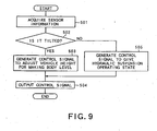
- FIG. 9 illustrates the procedure for processing in the embodiment 5 that is carried out by the controller 5.
- a detection signal from the tilt angle sensor 3 is inputted into the controller 5 (at step 501), and it is determined whether the body 2 is tilted with respect to the level (at step 502).
- the target vehicle height for bringing the current tilt angle ⁇ to zero is calculated.
- the body 2 can be leveled by increasing the vehicle height on the side of the left-hand wheels 11, 13 and decreasing the vehicle height on the side of the right-hand wheels 12, 14.
- the target vehicle height on the side of the left-hand wheels 11, 13, and the target vehicle height on the side of the right-hand wheels 12, 14 that are required for making the body 2 level are calculated based on the detected tilt angle ⁇ , and a control signal i according to the target height and a control signal j for selecting the hydraulic pressure source are generated (at step 503), this control signal i being applied to the respective electromagnetic solenoids 51d to 54d of the directional flow control valves 51 to 54, and the control signal j being applied to the electromagnetic solenoid 55d of the hydraulic pressure source control valve 55.
- the directional flow control valves 51, 53 for the left-hand wheels 11, 13 are shifted to the vehicle-height increasing adjustment positions 51a, 53a, the vehicle height on the side of the left-hand wheels 11, 13 being adjusted for an increased height.
- the directional flow control valves 52, 54 for the right-hand wheels 12, 14 are shifted to the vehicle-height decreasing adjustment positions 51b, 54b, the vehicle height on the side of the right-hand wheels 12, 14 being adjusted for a decreased height.
- the hydraulic pressure source control valve 55 is shifted to the hydraulic pump selecting position 55b, the delivery port of the hydraulic pump 7 being connected to the respective hydraulic oil chambers of the hydraulic suspension cylinders 21 to 24 (at step 504).
- the tilt angle ⁇ is determined to be zero (NO at step 502) and therefore, the directional flow control valves 51 to 54 are shifted to the connecting positions 51c to 54c, respectively.
- the "hydraulic suspension operating state" is given (at step 505, 504).
- the vehicle is a construction machine, it is normally left standing while the work machine 6 is being operated for carrying out the work. During the work, the rotating superstructure 2b is turned or the work machine 6 is operated, resulting in the body 2 being jolted. Therefore, if the "hydraulic suspension operating state" is given while the vehicle 1 is standing (i.e., working), the body 2 will jolt, and there arises the possibility of the vehicle 1 being overturned due to the change in the position of the center of gravity of the vehicle 1. Thus, when the vehicle 1 is standing (working), it is preferable that the vehicle height adjustment be performed to maintain the levelness of the body 2 for prevention of the overturning caused by the jolt as a result of the work.
- FIG. 10 illustrates the procedure for processing in the embodiment 6 that is carried out by the controller 5.
- a detection signal from the tilt angle sensor 3 is inputted into the controller 5 (at step 601), and it is determined whether the body 2 is currently tilted (at step 602).
- the vehicle height adjustment is performed in the same manner as that in the step 503, 504 in FIG. 9 to level the posture of the body 2 (at step 603, 604).
- step 602 when it has been determined that the body 2 is currently not tilted, information about whether the vehicle 1 is traveling, i.e., a detection signal from the vehicle speed sensor 4, is inputted into the controller 5 (at step 605), and based on the result of detection by the vehicle speed sensor 4, it is determined whether the vehicle 1 is traveling or standing (at step 607).
- a detection signal from the vehicle speed sensor 4 is inputted into the controller 5 (at step 605), and based on the result of detection by the vehicle speed sensor 4, it is determined whether the vehicle 1 is traveling or standing (at step 607).
- the program proceeds to the step 603, and the vehicle height adjustment is performed to level the posture of the body 2 (at step 603, 604).
- a control signal j for shifting the hydraulic pressure source control valve 55 to the accumulator selecting position 55a is generated to give the "hydraulic suspension operating state" (at step 608), and this control signal j is applied to the electromagnetic solenoid 55d of the hydraulic pressure source control valve 55.
- the hydraulic pressure source control valve 55 is shifted to the accumulator selecting position 55a, thereby the "hydraulic suspension operating state” being given (at step 604).
- the vehicle height adjustment is performed to maintain the levelness of the body 2, whereby the overturning caused by the jolt as a result of the work can be prevented.
- the processing in addition to information about whether the vehicle 1 is traveling (i.e., a detection signal from the vehicle speed sensor 4), information about whether the vehicle 1 is working is inputted into the controller 5 (at step 605).
- the information about whether the vehicle 1 is working can be acquired as, for example, a detection value given by the sensor which detects the operating position of the lever for operating the work machine 6, or a detection value given by the sensor which detects the hydraulic pressure in the hydraulic circuit for driving the work machine 6.
- step 605 whether the vehicle 1 is working is determined based on the detection signal from the sensor (at step 606).
- the program proceeds to the step 603 and the vehicle height adjustment is performed to level the posture of the body 2 (at step 603, 604).
- the vehicle height adjustment is performed to level the posture of the body 2 (at step 603, 604).
- the vehicle height adjustment is performed to maintain the levelness of the body 2, thus the overturning caused by the jolt as a result of the work can be prevented.
- a detection signal from the vehicle speed sensor 4 is used.
- a detection value given by the sensor which detects the operating position of the lever for traveling the vehicle or a detection value given by the sensor which detects the hydraulic pressure in the hydraulic circuit for driving the base carrier (for instance, the delivery pressure for the hydraulic motor for traveling) may be used as information about whether or not the vehicle is traveling.
- the vehicle height is adjusted such that the posture of the body 2 is matched to the horizontal posture (the tilt angle being zero degree).
- the posture of the body 2 may be brought closer to the horizontal posture for matching the posture of the body to a substantially horizontal posture.
- the posture of the body 2 may be brought to a posture (a tilt angle of 5 degree, for example) close to the exact horizontal posture to be matched to a substantially horizontal posture.
- the posture of the body 2 is matched to the horizontal posture or to a substantially horizontal posture.
- the target vehicle height may be set at a vehicle height corresponding to a certain tilt angle not exceeding the maximum tolerable tilt angle ⁇ m so as to hold the tilt angle ⁇ of the body 2 below the maximum tolerable tilt angle ⁇ m.
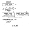
- FIG. 11 illustrates the procedure for processing in the embodiment 7 that is carried out by the controller 5.
- a detection signal from the tilt angle sensor 3 is inputted into the controller 5 (at step 701), and it is determined that the current tilt angle ⁇ for the body 2 is equal to or smaller than the maximum tolerable tilt angle ⁇ m (at step 702).
- the vehicle height adjustment is performed in the same manner as that in the step 503, 504 in FIG. 9 (or the step 603, 604 in FIG. 10) to bring the posture of the body 2 closer to the horizontal posture (at step 703, 704).
- a control signal j for shifting the hydraulic pressure source control valve 55 to the accumulator selecting position 55a to give the "hydraulic suspension operating state" is generated in the same manner as that in the step 505, 504 in FIG. 9 (or the step 608, 604 in FIG. 10) (at step 705).
- This control signal j is applied to the electromagnetic solenoid 55d of the hydraulic pressure source control valve 55.
- the hydraulic pressure source control valve 55 is shifted to the accumulator selecting position 55a, thereby the "hydraulic suspension operating state" being given (at step 704).
- the vehicle height is adjusted to bring the posture of the body 2 to a posture closer to the horizontal posture, and when the current tilt angle reaches a certain tilt angle equal to or smaller than the maximum tolerable tilt angle ⁇ m (i.e., when the target vehicle height is reached), the vehicle height adjustment is terminated, thereby the "hydraulic suspension operating state" being given.
- the tilt angle for the body 2 is held to be equal to or smaller than the maximum tolerable tilt angle ⁇ m, and thus the overturning can be prevented.
- the vehicle height adjusting means is constituted by a pipe line 33, an accumulator 34, directional flow control valves 51, 52, and a hydraulic pressure source control valve 55.
- the present invention is not limited to the vehicle height adjusting means of the above-described configuration.
- the vehicle height adjusting means of any other configurations may be employed as long as the vehicle height adjusting means includes an oil-gas pressure spring which comprises a gas chamber, an oil chamber, a spring member and a damper member, and performs the compression of the gas in the gas chamber via oil.
- the vehicle height adjusting means may be configured so that it includes a gas spring (an air spring) that utilizes the restitution of the compressed gas such as air, nitrogen gas, etc.
Landscapes
- Engineering & Computer Science (AREA)
- Mining & Mineral Resources (AREA)
- Civil Engineering (AREA)
- General Engineering & Computer Science (AREA)
- Structural Engineering (AREA)
- Physics & Mathematics (AREA)
- Fluid Mechanics (AREA)
- Vehicle Body Suspensions (AREA)
Abstract
Description
Therefore, the
Claims (4)
- A wheel-type construction machine (1) having a body (2) that is connected to wheels (11, 12) through hydraulic suspension cylinders (21, 22), comprising:a tilt angle sensor (3) for detecting a tilt angle in rolling directions of the body (2);a vehicle speed sensor (4) for detecting a vehicle speed; anda controller (5) for performing a control of shutting off inflow and outflow of a hydraulic oil for the hydraulic suspension cylinders (21, 22) when the tilt angle detected by the tilt angle sensor (3) exceeds a maximum tolerable tilt angle based on detection values given by the tilt angle sensor (3) and the vehicle speed sensor (4),
- The wheel-type construction machine of claim 1, wherein the maximum tolerable tilt angle is determined according to a vehicle speed detected by the vehicle speed sensor (4).
- A wheel-type construction machine (1) having a body (2) that is connected to wheels (11, 12) through hydraulic suspension cylinders (21, 22), comprising:a tilt angle sensor (3) for detecting a tilt angle in rolling directions of the body (2);vehicle height adjusting means (33, 34, 51, 52, 55) for adjusting a vehicle height by controlling inflow and outflow of a hydraulic oil for the hydraulic suspension cylinders (21, 22); andcontrolling means (5) for controlling the vehicle height adjusting means (33, 34, 51, 52, 55) to bring the tilt angle of the body (2) to being equal to or smaller than the maximum tolerable tilt angle when the tilt angle detected by the tilt angle sensor (3) exceeds a maximum tolerable tilt angle.
- A wheel-type construction machine (1) with which a body (2) is connected to wheels (11, 12) through hydraulic suspension cylinders (21, 22), comprising:a tilt angle sensor (3) for detecting a tilt angle in the rolling directions of the body (2);vehicle height adjusting means (33, 34, 51, 52, 55) for adjusting a vehicle height by controlling inflow and outflow of a hydraulic oil for the hydraulic suspension cylinders (21,22); andcontrolling means (5) for controlling the vehicle height adjusting means (33, 34, 51, 52, 55) to bring the body (2) close to the horizontal posture according to the tilt angle detected by the tilt angle sensor (3).
Applications Claiming Priority (2)
| Application Number | Priority Date | Filing Date | Title |
|---|---|---|---|
| JP2003409473 | 2003-12-08 | ||
| JP2003409473 | 2003-12-08 |
Publications (2)
| Publication Number | Publication Date |
|---|---|
| EP1541773A2 true EP1541773A2 (en) | 2005-06-15 |
| EP1541773A3 EP1541773A3 (en) | 2005-10-05 |
Family
ID=34510478
Family Applications (1)
| Application Number | Title | Priority Date | Filing Date |
|---|---|---|---|
| EP04029058A Withdrawn EP1541773A3 (en) | 2003-12-08 | 2004-12-08 | Wheel-type construction machine |
Country Status (1)
| Country | Link |
|---|---|
| EP (1) | EP1541773A3 (en) |
Cited By (6)
| Publication number | Priority date | Publication date | Assignee | Title |
|---|---|---|---|---|
| US20120065840A1 (en) * | 2009-04-17 | 2012-03-15 | Volvo Construction Equipment Ab | Vehicle and method for operating a vehicle |
| ITBZ20110007A1 (en) * | 2011-02-22 | 2012-08-23 | Martin Monsorno | DETECTOR OF DANGERS OF TILTING AND CONTRASTING HAZARDS ROUTES FOR VEHICLES, IN PARTICULAR AGRICULTURALS. |
| CN104088317A (en) * | 2014-07-12 | 2014-10-08 | 黄健 | Vehicle-mounted stabilizing structure of wheel-type hydraulic excavator |
| EP2902221A1 (en) | 2014-02-03 | 2015-08-05 | CNH Industrial Italia S.p.A. | Roll-over protection system |
| CN114846257A (en) * | 2020-03-19 | 2022-08-02 | 株式会社小松制作所 | Hydraulic control system for transmission |
| US12385224B2 (en) | 2022-03-31 | 2025-08-12 | Hitachi Construction Machinery Co., Ltd. | Wheeled construction machine |
Family Cites Families (4)
| Publication number | Priority date | Publication date | Assignee | Title |
|---|---|---|---|---|
| DE3632416A1 (en) * | 1986-09-24 | 1988-04-07 | Schaeff Karl Gmbh & Co | Centre pivot-steered work vehicle with height adjustable wheels |
| US5684698A (en) * | 1994-04-15 | 1997-11-04 | Kabushiki Kaisha Toyoda Jidoshokki Seisakusho | Vehicle attitude and average height control apparatus |
| JPH1044735A (en) * | 1996-08-01 | 1998-02-17 | Komatsu Ltd | Excavation work vehicle suspension device and control method thereof |
| JP4343399B2 (en) * | 2000-05-29 | 2009-10-14 | 住友ナコ マテリアル ハンドリング株式会社 | Industrial vehicle swing control device |
-
2004
- 2004-12-08 EP EP04029058A patent/EP1541773A3/en not_active Withdrawn
Cited By (11)
| Publication number | Priority date | Publication date | Assignee | Title |
|---|---|---|---|---|
| US20120065840A1 (en) * | 2009-04-17 | 2012-03-15 | Volvo Construction Equipment Ab | Vehicle and method for operating a vehicle |
| US8694204B2 (en) * | 2009-04-17 | 2014-04-08 | Volvo Construction Equipment Ab | Vehicle and method for operating a vehicle |
| EP2419286A4 (en) * | 2009-04-17 | 2014-06-04 | Volvo Constr Equip Ab | VEHICLE AND METHOD FOR OPERATING A VEHICLE |
| ITBZ20110007A1 (en) * | 2011-02-22 | 2012-08-23 | Martin Monsorno | DETECTOR OF DANGERS OF TILTING AND CONTRASTING HAZARDS ROUTES FOR VEHICLES, IN PARTICULAR AGRICULTURALS. |
| EP2902221A1 (en) | 2014-02-03 | 2015-08-05 | CNH Industrial Italia S.p.A. | Roll-over protection system |
| US9399382B2 (en) | 2014-02-03 | 2016-07-26 | Cnh Industrial America Llc | Roll-over protection system |
| CN104088317A (en) * | 2014-07-12 | 2014-10-08 | 黄健 | Vehicle-mounted stabilizing structure of wheel-type hydraulic excavator |
| CN114846257A (en) * | 2020-03-19 | 2022-08-02 | 株式会社小松制作所 | Hydraulic control system for transmission |
| CN114846257B (en) * | 2020-03-19 | 2024-04-16 | 株式会社小松制作所 | Hydraulic control system for transmission |
| US12241545B2 (en) | 2020-03-19 | 2025-03-04 | Komatsu Ltd. | Hydraulic control system for transmission |
| US12385224B2 (en) | 2022-03-31 | 2025-08-12 | Hitachi Construction Machinery Co., Ltd. | Wheeled construction machine |
Also Published As
| Publication number | Publication date |
|---|---|
| EP1541773A3 (en) | 2005-10-05 |
Similar Documents
| Publication | Publication Date | Title |
|---|---|---|
| JP4557696B2 (en) | Wheeled construction machine | |
| US20070073461A1 (en) | Vehicle suspension control | |
| EP0607516B1 (en) | Anti-roll system for wheeled vehicles | |
| JP2565384B2 (en) | Control device for automobile active suspension | |
| US6650985B2 (en) | Skid steer vehicle having anti-rolling system | |
| EP0796749B1 (en) | Industrial vehicle | |
| US20030116936A1 (en) | Skid steer loader suspension | |
| US20030125858A1 (en) | Skid steer vehicle with self-leveling suspension | |
| US20030121183A1 (en) | Skid steer vehicle with suspension locking by manipulation of loader or bucket controls | |
| JPH03511A (en) | Car height control method for vehicle with car height adjuster | |
| CA2254729C (en) | Axle pivot control method and apparatus for industrial vehicle | |
| US20030122329A1 (en) | Manual suspension locking of a skid steer vehicle having a sprung suspension | |
| EP0311114A2 (en) | Actively controlled suspension system for automotive vehicles with vehicular speed dependent variable damping characteristics | |
| CN117125152A (en) | Suspension system, engineering vehicle and suspension system control method | |
| JP4972479B2 (en) | Active suspension device for work vehicle | |
| JPS6212409A (en) | Rolling preventive device for automobile | |
| CN110789285B (en) | Oil-gas suspension device for remote-controlled vehicle, control method and remote-controlled vehicle | |
| JP2001047834A (en) | Vehicle leveling device | |
| EP0315457B1 (en) | Suspension control apparatus and method for a vehicle | |
| JP2008247357A (en) | Suspension control device | |
| JP5135023B2 (en) | Suspension characteristic control device | |
| JPH08268137A (en) | Rollover prevention device for dump trucks | |
| JP2009023595A (en) | Suspension device of carrier vehicle | |
| JP2008230466A (en) | Suspension control device | |
| JP2004276854A (en) | Vehicle spring control device |
Legal Events
| Date | Code | Title | Description |
|---|---|---|---|
| PUAI | Public reference made under article 153(3) epc to a published international application that has entered the european phase |
Free format text: ORIGINAL CODE: 0009012 |
|
| AK | Designated contracting states |
Kind code of ref document: A2 Designated state(s): AT BE BG CH CY CZ DE DK EE ES FI FR GB GR HU IE IS IT LI LT LU MC NL PL PT RO SE SI SK TR |
|
| AX | Request for extension of the european patent |
Extension state: AL BA HR LV MK YU |
|
| PUAL | Search report despatched |
Free format text: ORIGINAL CODE: 0009013 |
|
| AK | Designated contracting states |
Kind code of ref document: A3 Designated state(s): AT BE BG CH CY CZ DE DK EE ES FI FR GB GR HU IE IS IT LI LT LU MC NL PL PT RO SE SI SK TR |
|
| AX | Request for extension of the european patent |
Extension state: AL BA HR LV MK YU |
|
| AKX | Designation fees paid | ||
| STAA | Information on the status of an ep patent application or granted ep patent |
Free format text: STATUS: THE APPLICATION IS DEEMED TO BE WITHDRAWN |
|
| 18D | Application deemed to be withdrawn |
Effective date: 20060405 |
|
| REG | Reference to a national code |
Ref country code: DE Ref legal event code: 8566 |