EP1541430A1 - Squib - Google Patents
Squib Download PDFInfo
- Publication number
- EP1541430A1 EP1541430A1 EP04028603A EP04028603A EP1541430A1 EP 1541430 A1 EP1541430 A1 EP 1541430A1 EP 04028603 A EP04028603 A EP 04028603A EP 04028603 A EP04028603 A EP 04028603A EP 1541430 A1 EP1541430 A1 EP 1541430A1
- Authority
- EP
- European Patent Office
- Prior art keywords
- squib
- substrate
- igniting agent
- ignition
- pin
- Prior art date
- Legal status (The legal status is an assumption and is not a legal conclusion. Google has not performed a legal analysis and makes no representation as to the accuracy of the status listed.)
- Granted
Links
Images




Classifications
-
- B—PERFORMING OPERATIONS; TRANSPORTING
- B60—VEHICLES IN GENERAL
- B60R—VEHICLES, VEHICLE FITTINGS, OR VEHICLE PARTS, NOT OTHERWISE PROVIDED FOR
- B60R21/00—Arrangements or fittings on vehicles for protecting or preventing injuries to occupants or pedestrians in case of accidents or other traffic risks
- B60R21/02—Occupant safety arrangements or fittings, e.g. crash pads
- B60R21/16—Inflatable occupant restraints or confinements designed to inflate upon impact or impending impact, e.g. air bags
- B60R21/26—Inflatable occupant restraints or confinements designed to inflate upon impact or impending impact, e.g. air bags characterised by the inflation fluid source or means to control inflation fluid flow
-
- F—MECHANICAL ENGINEERING; LIGHTING; HEATING; WEAPONS; BLASTING
- F42—AMMUNITION; BLASTING
- F42B—EXPLOSIVE CHARGES, e.g. FOR BLASTING, FIREWORKS, AMMUNITION
- F42B3/00—Blasting cartridges, i.e. case and explosive
- F42B3/10—Initiators therefor
- F42B3/12—Bridge initiators
- F42B3/121—Initiators with incorporated integrated circuit
-
- B—PERFORMING OPERATIONS; TRANSPORTING
- B60—VEHICLES IN GENERAL
- B60R—VEHICLES, VEHICLE FITTINGS, OR VEHICLE PARTS, NOT OTHERWISE PROVIDED FOR
- B60R21/00—Arrangements or fittings on vehicles for protecting or preventing injuries to occupants or pedestrians in case of accidents or other traffic risks
- B60R21/02—Occupant safety arrangements or fittings, e.g. crash pads
- B60R21/16—Inflatable occupant restraints or confinements designed to inflate upon impact or impending impact, e.g. air bags
- B60R21/26—Inflatable occupant restraints or confinements designed to inflate upon impact or impending impact, e.g. air bags characterised by the inflation fluid source or means to control inflation fluid flow
- B60R2021/26029—Ignitors
Definitions
- the present invention relates to a squib (ignition apparatus) of an occupant protection apparatus that is mounted in a vehicle or the like.
- supplemental restraint systems such as airbags and pretensioners in order to protect an occupant of a vehicle or the like
- a supplemental restraint system is placed in a required location, and when an impact acts on a vehicle, this impact is detected by a sensor and the supplemental restraint system protects the occupant by temporarily restraining the occupant such that the occupant does not collide with an object in the vehicle interior.
- a connection between a control unit that controls the supplemental restraint systems and a squib that operates the supplemental restraint systems has been, for example, a simple 1 to 1 connection (i.e., a peer to peer connection).
- a simple 1 to 1 connection i.e., a peer to peer connection.
- connecting wires i.e., harnesses
- JP-A Japanese Patent Application Laid-Open
- a connection between a control unit and a squib of a supplemental restraint system is made using a bus wire that is capable of transmitting power and control signals, and a plurality of supplemental restraint systems that are connected to the bus wire are controlled by a single control unit using ignition control based on communication that specifies the relevant squib.
- a squib in order for a squib to be connected to a bus wire and receive ignition control based on communication from a control unit, it is necessary for the squib side to be provided with a communication circuit that is used to communicate with the control unit, and an ignition circuit that supplies power to an ignition element in order to ignite an explosive that causes the supplemental restraint system to operate.
- a control IC that controls communication and ignition is placed between the ignition element and an external connection terminal that is used to connect the squib to the bus wire (see, for example, Japanese Patent No. 3294582).
- the squib when the squib is provided with a communication circuit and an ignition circuit, as is the case with a conventional squib, sufficient consideration needs to be given to ensuring that the bus wire is not electrically affected by the squib that is provided in the supplemental restraint system being operated, and the problem arises that the reliability of the bus wire needs to be increased still further.
- the present invention was conceived in view of the above described circumstances and it is an object thereof to provide a squib that, when causing a supplemental restraint system to operate, does not electrically affect an external signal wire that supplies power and control signals.
- the first aspect of the present invention is a squib for an occupant protection apparatus that, based on an ignition command signal received from an external signal line (for example, the bus wire 3 of the embodiments described below), ignites an explosive (for example, the igniting agent 53 of the embodiments described below) so as to cause a supplemental restraint system to be operated, comprising: an ignition device (for example, the ignition element 30 of the embodiments described below) that ignites the explosive; a communication/ ignition control section (for example, the IC substrate 54 of the embodiments described below) that receives the ignition command signal, and that controls an igniting of the explosive by the ignition device; and a connecting terminal (for example, the pins 51a, 51b or 59a of the embodiments described below) that connects the communication/ ignition control section to the external signal line, wherein when the explosive is being ignited by the ignition device, the communication/ ignition control section is separated from the connecting terminal by pressure or heat generated from the explosive.
- an ignition device for example, the ignition element 30 of the
- the squib according to the first aspect of the present invention because the connection between the external signal wire and the communication/ ignition control section is broken by the pressure or heat generated from the ignited explosive, even if the communication/ ignition control section is damaged by the pressure or heat that is generated from the explosive, it is possible to prevent any electrical effects from being generated on the bus wire side that had been connected to the communication/ignition control section. Accordingly, a squib that is provided in the supplemental restraint system being operated does not electrically affect the external signal wire that supplies power and control signals. Consequently, the effect is obtained that it is possible to achieve a squib that further improves the reliability of the external signal wire.
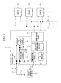
- FIG 1 is a block diagram showing an outline of an ignition system of an occupant protection apparatus that is provided with the squib (ignition apparatus) according to the first embodiment of the present invention.
- the occupant protection apparatus that is provided with the squib of the present embodiment is particularly useful if it is used by being mounted in a vehicle such as an automobile. As an example, a description is given of when the occupant protection apparatus is mounted in an automobile.
- a control unit 1 is a control device that forms the center of an occupant protection apparatus that protects an occupant of a vehicle from an impact acting on the vehicle.
- Squibs 2a, 2b, 2c, ... of a plurality of supplemental restraint systems (not shown) that are provided in suitable locations in the vehicle in order to protect an occupant are provided 1 to 1 for the auxiliary restraining systems, and are connected in parallel to the control unit 1 using, for example, an unbalanced type of bus line 3 in which one of two pairs of wires is grounded.
- squibs 2a, 2b, 2c, ... operate the supplemental restraint systems by igniting the igniting agent after receiving command signals (i.e., ignition command instructions) that are sent to the designated communication addresses of the squibs 2a ,2b, 2c, ... from the control unit 1.
- command signals i.e., ignition command instructions
- a collision determining section 11 in the form of a central processing unit (CPU) is provided in the control unit 1.
- the collision determining section 11 determines whether or not an impact that requires the occupant protection apparatuses to be operated has acted on the vehicle due to the vehicle colliding with another object based on output signals from a front sensor 4 that is provided in a front portion of the vehicle and is connected via a communication circuit 12 to the collision determining section 11 and that detects a rate of acceleration due to a deformation of the front portion of the vehicle, and based on output signals from a G sensor 13 that is provided in the control unit 1 and detects the rate of acceleration of the vehicle.
- a front sensor 4 that is provided in a front portion of the vehicle and is connected via a communication circuit 12 to the collision determining section 11 and that detects a rate of acceleration due to a deformation of the front portion of the vehicle, and based on output signals from a G sensor 13 that is provided in the control unit 1 and detects the rate of acceleration of the vehicle.
- a communication circuit 14 that supplies power (i.e., electrical energy) to the squibs 2a, 2b, 2c, ... via the bus wire 3 and that performs control signal communication with the squibs 2a, 2b, 2c, ... by designating the communication addresses thereof is provided in the control unit 1.
- an ignition command signal i.e., an ignition command instruction
- an ignition command signal is sent by the communication circuit 14 via the bus line 3 to the squibs 2a, 2b, 2c, ... in order to operate a supplemental restraint system (not shown).
- a vehicle mounted battery 7 that stores power used by the vehicle is also connected to the control unit 1 via an ignition switch (IG ⁇ SW) 6 and a fuse 5 that is used to prevent current surges.
- Power from the vehicle mounted battery 7 that is input via a protective diode 15 that prevents current counter flow is supplied to a +5v power supply 16 that creates a power supply for the CPU and the like that constitute the collision determining section 11.
- this power is supplied to the communication circuit 14 that supplies power to the squibs 2a, 2b, 2c, ....
- control unit I is also provided with a backup condenser 17 that backs up the power supply by storing power, protective diodes 18a and 18b that charge the backup condenser 17, and booster circuit 19 such that the control unit 1 operates for a fixed time even if the supply of power from the vehicle mounted battery 7 is stopped.
- FIG. 2 is a view showing specifications of signals that are transmitted and received by the bus wire 3 between the communication circuit 14 and the squibs 2a, 2b, 2c, ..., with the horizontal axis taken as [time t] and the vertical axis taken as [voltage V].
- the bus wire 3 is controlled by the control unit 1 so as to altematingly repeat a [communication phase] that designates communication addresses and then transmits and receives control signals between the control unit 1 and the squibs 2a, 2b, 2c, ..., and a [power supply phase] that supplies power from the control unit 1 to the squibs 2a, 2b, 2c, ....
- [power supply phase] power when the potential difference between the two wires is 11 [V] is supplied from the control unit 1 to the squibs 2a, 2b, 2c, ....
- FIG 3 is a block diagram showing details of the squib of the present embodiment, and shows the squib 2a in detail as an example. Note that the other squibs 2b, 2c, ... that are connected to the bus wire 3 all have the same apparatus structure as the squib 2a.
- a control circuit 21 that executes ignition control based on a diagnosis of communications by the bus wire 3 and on instructions from the control unit 1 is provided in the squib 2a.
- Control signals i.e., commands
- response signals i.e., responses
- Power supplied from the bus wire 3 is supplied to a +5V power supply 24 that creates a power supply for the control circuit 21 and the like.
- Power from the bus wire 3 is also supplied via a protective diode 25 to a booster circuit 26 that generates the power required for the squib 2a to ignite the igniting agent and operate the supplemental restraint system.
- a condenser 28 is connected via a protective diode 27 to an output of the booster circuit 26.
- the power that is boosted by the booster circuit 26 and is required for the squib 2a to ignite the igniting agent and operate the supplemental restraint system can be stored in the condenser 28.
- a series circuit made up of a switching element 29, an ignition element 30 that ignites the igniting agent incorporated in the squib 2a, and a switching element 31 is connected to an output (i.e., a cathode terminal) of the protective diode 27.
- one terminal of the ignition element 30 is connected via the switching element 29 to the output of the protective diode 27, while the other terminal of the ignition element 30 is grounded via the switching element 31.
- Control terminals that control the conduction and cutoff of the switching element 29 and the switching element 31 are both connected to the control circuit 21.
- the control unit 1 supplies power to the bus wire 3 and transmits a charge power command, then because the power required, for example, for the ignition element 30 to ignite the igniting agent and operate the supplemental restraint system is stored in the condenser 28 of the squib 2a, if, in this state, the control unit 1 sends an ignition execute signal (i.e., an ignition execute command) to the squib 2a, the control circuit 21 of the squib 2a is able to conduct the switching element 29 and the switching element 31 such that power stored in the condenser 28 is supplied to the switching element 30, resulting in the igniting agent stored in the squib 2 exploding and the supplemental restraint system thereby being operated.
- an ignition execute signal i.e., an ignition execute command
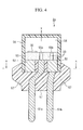
- FIG. 4 shows the physical layout structure of the squib of the present embodiment, and is a vertical cross-sectional view of a squib.
- the squib 2a is shown in detail as an example. Note that the other squibs 2b, 2c, ... that are connected to the bus wire 3 all have the same physical layout structure as the squib 2a.
- an igniting agent 53 that ignites a gas generating agent of a supplemental restraint system is positioned above a pin 51a, which is a connecting terminal that is provided in order to make a connection with a two-wire system bus wire 3, which is an external signal wire, and above a header 52 that is provided with a pin 51b, which is a connecting terminal.
- an IC substrate 54 on which are mounted the aforementioned control circuit 21, the reception buffer 22, the transmission buffer 23, the +5V power supply 24, the protective diode 25, the booster circuit 26, the protective diode 27, the condenser 28, the switching element 29, the ignition element 30, and the switching element 31 is positioned above the igniting agent 53.
- the pin 51b and the header 52 are formed from a melting material.
- the header 52 is positioned so as to surround the pin 51a, as is shown in the cross-sectional view taken in the horizontal direction along the line A-A shown in FIG. 5.
- the space between the pin 51a and the header 52 is filled with a non-conductive material such as glass in order to fix the pin 51 a in position.
- the ignition element 30 that is connected to the switching element 29 and the switching element 31.
- joining portions 55a and 55b are provided in two locations bridging the igniting agent 53 so as to connect the IC substrate 54 with the pin 51 a and the header 52.
- the IC substrate 54, the igniting agent 53, the pin 51a, and the header 52 are covered by a circular cylinder shaped cap 56 whose top portion is closed off. Furthermore, the IC substrate 54, the igniting agent 53, the pin 51a, and the header 52 that are covered by the cap 56 are formed integrally by being covered by a resin mold 57 that is made to extend across the portions of the pins 51a and 51 b using a molding process. Note that, in the above description, the materials used for each portion are merely examples thereof and a variety of modifications can be employed such as, for example, using a cap 56 formed from metal.
- the supplemental restraint system is operated and the IC substrate 54 is blown in the direction of the top surface (i.e., in the X direction shown in FIG. 4) of the squib 2a by the pressure that is generated from the ignited igniting agent 53 and is separated from the top surface of the squib 2a. Accordingly, either the joining portions 55a and 55b in the two locations that connect the IC substrate 54 with the pin 51a and the header 52 are cut, or the joining portions 55a and 55b in the two locations are melted by the heat generated from the ignited igniting agent 53.
- bus wire 3 described in the above embodiment may also be, for example, a non-balanced type of bus wire in which neither of two pairs of wires are grounded.
- a supplemental restraint system when a supplemental restraint system is operated by igniting an igniting agent 53, by separating the IC substrate 54 from pins 51a and 51b that are used to connect the IC bus substrate 54 with the bus wire 3 using the pressure or heat generated from the ignited igniting agent 53, the connection between the bus wire 3 and the IC substrate 54 is broken. As a result, even if the IC substrate 54 is damaged by the pressure or heat that is generated from the ignited igniting agent 53, it is possible to prevent any electrical effects from being generated in the bus wire 3 that had been connected to the IC substrate 54.
- a squib that is provided in the supplemental restraint system being operated does not electrically affect the bus wire 3, which supplies power and control signals. Consequently, the effect is obtained that it is possible to achieve a squib that further improves the reliability of the bus wire 3.
- the squib of the present embodiment differs from the squib described in the first embodiment only in the physical layout structure of the component elements constituting the squib. Accordingly, the structure of the ignition system of the occupant protection apparatus in which the squib of the present embodiment is provided, as well as the circuit structure (i.e., the apparatus structure) of the squib of the present embodiment and the signal specifications of the bus wire are identical with the structure of the ignition system as well as the circuit structure (i.e., the apparatus structure) of the squib and the signal specifications of the bus wire of the first embodiment. Therefore a description thereof is omitted.
- the physical layout structure of the component elements that form the squib (ignition apparatus) of the present embodiment is described.
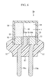
- FIG. 6 shows the physical layout structure of the squib of the present embodiment, and is a vertical cross-sectional view of a squib.
- the squib 2a is shown in detail as an example.
- the physical layout structure of the squib of the present embodiment is the same as that of the squib of the first embodiment in that the igniting agent 53 and the IC substrate 54 are placed above the pin 51 a and the header 52, however, the placement of the igniting agent 53 and the IC substrate 54 is different from that of the squib of the first embodiment.
- the igniting agent 53 and the IC substrate 54 that have been partitioned from each other are placed respectively so as to cover top surfaces of a pin 51a, which is a connecting terminal that is provided in order to make a connection with a two-wire system bus wire 3, which is an external signal wire, and of a header 52 that is provided with a pin 51b, which is a connecting terminal.
- the ignition element 30 that is connected to the switching element 29 and the switching element 31.
- joining portions 58a and 58b are provided in two locations bridging the igniting agent 53, a part of which is inserted into the gap between the IC substrate 54 and the pin 51a and header 52, so as to connect the IC substrate 54 with the pin 51 a and the header 52.
- the IC substrate 54, the igniting agent 53, the pin 51 a, and the header 52 are covered by a circular cylinder shaped cap 56 whose top portion is closed off. Furthermore, the IC substrate 54, the igniting agent 53, the pin 51a, and the header 52 that are covered by the cap 56 are formed integrally by being covered by a resin mold 57 that is made to extend across the portions of the pins 51a and 51 b using a molding process. Note that, in the above description, the materials used for each portion are merely examples thereof and a variety of modifications can be employed such as, for example, using a cap 56 formed from metal.
- the supplemental restraint system is operated and the IC substrate 54 is blown in the direction of the circumferential surface or the direction of the side surface (i.e., in the Y direction shown in FIG. 6) of the squib 2a by the pressure that is generated from the ignited igniting agent 53 and is separated from the circumferential surface or side surface of the squib 2a.
- the squib of the present embodiment in the same way as in the first embodiment, when a supplemental restraint system is operated by igniting an igniting agent 53, because the connection between the bus wire 3 and the IC substrate 54 is broken, even if the IC substrate 54 is damaged by the pressure or heat that is generated from the ignited igniting agent 53, it is possible to prevent any electrical effects from being generated in the bus wire 3 that had been connected to the IC substrate 54.
- a squib that is provided in the supplemental restraint system being operated does not electrically affect the bus wire 3, which supplies power and control signals. Consequently, the effect is obtained that it is possible to achieve a squib that further improves the reliability of the bus wire 3.
- the squib of the present embodiment differs from the squib described in the first and second embodiments only in the physical layout structure of the component elements constituting the squib. Accordingly, the structure of the ignition system of the occupant protection apparatus in which the squib of the present embodiment is provided, as well as the circuit structure (i.e., the apparatus structure) of the squib of the present embodiment are identical with the structure of the ignition system as well as the circuit structure (i.e., the apparatus structure) of the squib of the first and second embodiments. Therefore a description thereof is omitted.
- the physical layout structure of the component elements that form the squib of the present embodiment is described.
- FIG. 7 is a vertical cross-sectional view of a squib showing the physical layout structure of the squib of the present embodiment, and in the same way as in the first and second embodiments, the squib 2a is shown in detail as an example.
- the physical layout structure of the squib of the present embodiment is the same as that of the first and second embodiments in the placement of the igniting agent 53 and the IC substrate 54 above the header, however, the placement of the igniting agent 53 and the IC substrate 54 and the configuration of the pin that is a connecting terminal that is provided in order to make a connection with the bus wire 3, which is an external signal wire, are different from those of the squibs of the first and second embodiments.
- a pin 59a which is a connecting terminal that is provided in order to make a connection with the two-wire system bus wire 3, which is an external signal wire, extends (i.e., protrudes) beyond it's periphery
- the IC substrate 54 is placed on top of the pin 59a, which extends (i.e., protrudes) beyond the periphery
- a header 59b that is provided with the pin 51b, which is a connecting terminal, and that surrounds the periphery of the pin 59a.
- the IC substrate 54 is positioned so as to surround the pin 59a leaving a uniform space (i.e., gap) 60.
- the igniting agent 53 is placed above the IC substrate 54.
- the pin 51b and the header 59b are formed from a melting material.
- the space between the pin 59a and the header 59b is filled with a non-conductive material such as glass in order to fix the pin 59a in position.
- the ignition element 30 that is connected to the switching element 29 and the switching element 31.
- a joining portion 61 a that connects the IC substrate 54 with the pin 59a and a joining portion 61b that connects the IC substrate 54 with the header 59b are provided bridging the space 60.
- the joining portion 61a is positioned so as to surround the extending (i.e., protruding) pin 59a. Note that the joining portion 61a is only connected to the IC substrate 54 at the point B shown in FIG. 7, and the remaining portions thereof are insulated from the IC substrate 54.
- the IC substrate 54, the igniting agent 53, the pin 59a, and the header 59b are covered by a circular cylinder shaped cap 56 whose top portion is closed off. Furthermore, the IC substrate 54, the igniting agent 53, the pin 59a, and the header 59b that are covered by the cap 56 are formed integrally by being covered by a resin mold 57 that is made to extend across the portions of the pins 59a and 51b using a molding process. Note that, in the above description, the materials used for each portion are merely examples thereof and a variety of modifications can be employed such as, for example, using a cap 56 formed from metal.
- the supplemental restraint system is operated and the IC substrate 54 is blown in the direction of the pin 59a and the header 59b of the squib (i.e., in the Y direction shown in FIG. 7) of the squib 2a by the pressure that is generated from the ignited igniting agent 53.
- the joining portion 61 a that connects the IC substrate 54 with the pin 59a is cut under the principle of the IC substrate 54 acting as a guillotine at the portion along the line C-C in FIG. 7.
- connection between the pin 59a that is connected to the bus 3 and the IC substrate 54 is cut, even if the IC substrate 54 is damaged by the pressure or heat that is generated from the ignited igniting agent 53, it is possible to prevent any electrical effects from being generated on the bus wire 3 side that had been connected to the IC substrate 54.
- the squib of the present embodiment in the same way as in the first and second embodiments, when a supplemental restraint system is operated by igniting an igniting agent 53, because the connection between the bus wire 3 and the IC substrate 54 is broken, even if the IC substrate 54 is damaged by the pressure or heat that is generated from the ignited igniting agent 53, it is possible to prevent any electrical effects from being generated in the bus wire 3 that had been connected to the IC substrate 54.
- a squib that is provided in the supplemental restraint system being operated does not electrically affect the bus wire 3, which supplies power and control signals. Consequently, the effect is obtained that it is possible to achieve a squib that further improves the reliability of the bus wire 3.
- a squib that does not electrically affect an external signal wire that supplies power and command signals when a supplemental restraint system is operated.
- An igniting agent is positioned above a pin that is a connecting terminal that is provided in order to provide a connection with a two-wire system bus wire, which is an external signal wire, and above a header that is provided with a pin that is a connecting terminal.
- an IC substrate that controls communications and ignitions is positioned above the igniting agent. Between the igniting agent and the IC substrate is provided an ignition element.
- joining portions are provided in two locations bridging the igniting agent so as to connect the IC substrate with the pin and the header.
- the IC substrate, the igniting agent, the pin, and the header are covered by a circular cylinder shaped cap whose top portion is closed off. Furthermore, these are formed integrally by being covered by a resin mold that is made to extend across the portions of the pins using a molding process.
Landscapes
- Engineering & Computer Science (AREA)
- Computer Hardware Design (AREA)
- Microelectronics & Electronic Packaging (AREA)
- General Engineering & Computer Science (AREA)
- Physics & Mathematics (AREA)
- Fluid Mechanics (AREA)
- Mechanical Engineering (AREA)
- Air Bags (AREA)
Abstract
Description
- Priority is claimed on Japanese Patent Application No. 2003-408906, filed December 8, 2004, the contents of which are incorporated herein by reference.
- The present invention relates to a squib (ignition apparatus) of an occupant protection apparatus that is mounted in a vehicle or the like.
- In recent years, occupant protection apparatuses that use supplemental restraint systems such as airbags and pretensioners in order to protect an occupant of a vehicle or the like have become widespread. In these occupant protection apparatuses, a supplemental restraint system is placed in a required location, and when an impact acts on a vehicle, this impact is detected by a sensor and the supplemental restraint system protects the occupant by temporarily restraining the occupant such that the occupant does not collide with an object in the vehicle interior.
- Conventionally, in order to reduce the number of supplemental restraint systems placed in a vehicle, a connection between a control unit that controls the supplemental restraint systems and a squib that operates the supplemental restraint systems has been, for example, a simple 1 to 1 connection (i.e., a peer to peer connection). However, recently, due to the placement of supplemental restraint systems in various locations of a vehicle there has been a trend towards the number of supplemental restraint systems increasing. As a result, there have been demands for the connecting wires (i.e., harnesses) that connect control units and control units with squibs of supplemental restraint systems to be reduced as much as possible. Therefore, a method has been proposed (for example, in Japanese Patent Application Laid-Open (JP-A) Nos. 10-154992 and 2000-124932 in which a connection between a control unit and a squib of a supplemental restraint system is made using a bus wire that is capable of transmitting power and control signals, and a plurality of supplemental restraint systems that are connected to the bus wire are controlled by a single control unit using ignition control based on communication that specifies the relevant squib.
- On the other hand, in order for a squib to be connected to a bus wire and receive ignition control based on communication from a control unit, it is necessary for the squib side to be provided with a communication circuit that is used to communicate with the control unit, and an ignition circuit that supplies power to an ignition element in order to ignite an explosive that causes the supplemental restraint system to operate. In this squib, a control IC that controls communication and ignition is placed between the ignition element and an external connection terminal that is used to connect the squib to the bus wire (see, for example, Japanese Patent No. 3294582).
- However, in a conventional method of connecting a control unit to a squib for a supplemental restraint system using a bus wire, although it is possible to control a plurality of supplemental restraint systems efficiently using a single control unit, the only connecting wire that transmits power or control signals to the plurality of supplemental restraint systems is the bus wire. Therefore, the problem arises that the transmission of power or control signals via the bus wire needs to be extremely reliable. In particular, when the squib is provided with a communication circuit and an ignition circuit, as is the case with a conventional squib, sufficient consideration needs to be given to ensuring that the bus wire is not electrically affected by the squib that is provided in the supplemental restraint system being operated, and the problem arises that the reliability of the bus wire needs to be increased still further.
- The present invention was conceived in view of the above described circumstances and it is an object thereof to provide a squib that, when causing a supplemental restraint system to operate, does not electrically affect an external signal wire that supplies power and control signals.
- In order to solve the above problems the first aspect of the present invention is a squib for an occupant protection apparatus that, based on an ignition command signal received from an external signal line (for example, the
bus wire 3 of the embodiments described below), ignites an explosive (for example, theigniting agent 53 of the embodiments described below) so as to cause a supplemental restraint system to be operated, comprising: an ignition device (for example, theignition element 30 of the embodiments described below) that ignites the explosive; a communication/ ignition control section (for example, theIC substrate 54 of the embodiments described below) that receives the ignition command signal, and that controls an igniting of the explosive by the ignition device; and a connecting terminal (for example, thepins - In the squib provided with the above described structure, when a supplemental restraint system is operated using an explosive, because the connection between the external signal wire and the communication/ ignition control section is broken as a result of the connecting terminal, which connects the external signal wire to the communication/ ignition control section, being separated from the communication/ignition control section by the pressure or heat generated from the ignited explosive, even if the communication/ ignition control section is damaged by the pressure or heat that is generated from the ignited explosive, it is possible to prevent any electrical effects from being generated on the external signal wire side that had been connected to the communication/ ignition control section.
- According to the squib according to the first aspect of the present invention, because the connection between the external signal wire and the communication/ ignition control section is broken by the pressure or heat generated from the ignited explosive, even if the communication/ ignition control section is damaged by the pressure or heat that is generated from the explosive, it is possible to prevent any electrical effects from being generated on the bus wire side that had been connected to the communication/ignition control section. Accordingly, a squib that is provided in the supplemental restraint system being operated does not electrically affect the external signal wire that supplies power and control signals. Consequently, the effect is obtained that it is possible to achieve a squib that further improves the reliability of the external signal wire.
-
- FIG. 1 is a block diagram showing an outline of an ignition system of an occupant protection apparatus that is provided with the squib according to the first embodiment of the present invention.
- FIG. 2 is a block diagram showing details of the squib of the first embodiment.
- FIG 3 is a view showing specifications of signals that are transmitted and received via a bus wire in the first embodiment.
- FIG. 4 is a cross-sectional view in the vertical direction of a squib showing the physical layout structure of the squib of the first embodiment.
- FIG. 5 is a cross-sectional view in the horizontal direction of the squib of the first embodiment.
- FIG. 6 is a cross-sectional view in the vertical direction of a squib showing the physical layout structure of the squib of a second embodiment of the present invention.
- FIG. 7 is a cross-sectional view in the vertical direction of a squib showing the physical layout structure of the squib of a third embodiment of the present invention.
-
- While preferred embodiments of the invention have been described and illustrated above, it should be understood that these are exemplary of the invention and are not to be considered as limiting. Additions, omissions, substitutions, and other modifications can be made without departing from the spirit or scope of the present invention. Accordingly, the invention is not to be considered as limited by the foregoing description and is only limited by the scope of the appended claims.
- Embodiments of the present invention will now be described with reference made to the drawings.
- FIG 1 is a block diagram showing an outline of an ignition system of an occupant protection apparatus that is provided with the squib (ignition apparatus) according to the first embodiment of the present invention. Note that the occupant protection apparatus that is provided with the squib of the present embodiment is particularly useful if it is used by being mounted in a vehicle such as an automobile. As an example, a description is given of when the occupant protection apparatus is mounted in an automobile.
- In FIG. 1, a control unit 1 is a control device that forms the center of an occupant protection apparatus that protects an occupant of a vehicle from an impact acting on the vehicle.
Squibs bus line 3 in which one of two pairs of wires is grounded. Note that thesquibs igniting agent 53 described below) is incorporated inside each. Thesquibs squibs - A
collision determining section 11 in the form of a central processing unit (CPU) is provided in the control unit 1. Thecollision determining section 11 determines whether or not an impact that requires the occupant protection apparatuses to be operated has acted on the vehicle due to the vehicle colliding with another object based on output signals from a front sensor 4 that is provided in a front portion of the vehicle and is connected via acommunication circuit 12 to thecollision determining section 11 and that detects a rate of acceleration due to a deformation of the front portion of the vehicle, and based on output signals from aG sensor 13 that is provided in the control unit 1 and detects the rate of acceleration of the vehicle. - On the other hand, a
communication circuit 14 that supplies power (i.e., electrical energy) to thesquibs bus wire 3 and that performs control signal communication with thesquibs collision determining section 11 determines that an impact that requires the occupant protection apparatuses to be operated has acted on the vehicle due to the vehicle colliding with another object, an ignition command signal (i.e., an ignition command instruction) is sent by thecommunication circuit 14 via thebus line 3 to thesquibs - A vehicle mounted battery 7 that stores power used by the vehicle is also connected to the control unit 1 via an ignition switch (IG · SW) 6 and a
fuse 5 that is used to prevent current surges. Power from the vehicle mounted battery 7 that is input via aprotective diode 15 that prevents current counter flow is supplied to a +5v power supply 16 that creates a power supply for the CPU and the like that constitute thecollision determining section 11. In addition, this power is supplied to thecommunication circuit 14 that supplies power to thesquibs backup condenser 17 that backs up the power supply by storing power,protective diodes backup condenser 17, andbooster circuit 19 such that the control unit 1 operates for a fixed time even if the supply of power from the vehicle mounted battery 7 is stopped. - Here, a description will be given of the communication of control signals and power supply via the
bus 3 between thecommunication circuit 14 and thesquibs bus wire 3 between thecommunication circuit 14 and thesquibs bus wire 3 is controlled by the control unit 1 so as to altematingly repeat a [communication phase] that designates communication addresses and then transmits and receives control signals between the control unit 1 and thesquibs squibs bus wire 3 is 6 [V], and, in the same way, data "Low" (=0) is shown when the potential difference between the two wires is 3 [V]. Moreover, in [power supply phase], power when the potential difference between the two wires is 11 [V] is supplied from the control unit 1 to thesquibs - FIG 3 is a block diagram showing details of the squib of the present embodiment, and shows the
squib 2a in detail as an example. Note that theother squibs bus wire 3 all have the same apparatus structure as thesquib 2a. - In FIG 3, a
control circuit 21 that executes ignition control based on a diagnosis of communications by thebus wire 3 and on instructions from the control unit 1 is provided in thesquib 2a. Control signals (i.e., commands) are input into thecontrol circuit 21 from thebus wire 3 via areception buffer 22, and response signals (i.e., responses) responding to the control signals are output from thecontrol circuit 21 to thebus wire 3 via atransmission buffer 23. Power supplied from thebus wire 3 is supplied to a +5V power supply 24 that creates a power supply for thecontrol circuit 21 and the like. Power from thebus wire 3 is also supplied via aprotective diode 25 to abooster circuit 26 that generates the power required for thesquib 2a to ignite the igniting agent and operate the supplemental restraint system. - A
condenser 28 is connected via aprotective diode 27 to an output of thebooster circuit 26. The power that is boosted by thebooster circuit 26 and is required for thesquib 2a to ignite the igniting agent and operate the supplemental restraint system can be stored in thecondenser 28. Furthermore, in parallel with thecondenser 28, a series circuit made up of a switchingelement 29, anignition element 30 that ignites the igniting agent incorporated in thesquib 2a, and a switchingelement 31 is connected to an output (i.e., a cathode terminal) of theprotective diode 27. Specifically, one terminal of theignition element 30 is connected via the switchingelement 29 to the output of theprotective diode 27, while the other terminal of theignition element 30 is grounded via the switchingelement 31. Control terminals that control the conduction and cutoff of the switchingelement 29 and the switchingelement 31 are both connected to thecontrol circuit 21. - As a result, in an ignition system that is provided with the squib of the present embodiment, if the control unit 1 supplies power to the
bus wire 3 and transmits a charge power command, then because the power required, for example, for theignition element 30 to ignite the igniting agent and operate the supplemental restraint system is stored in thecondenser 28 of thesquib 2a, if, in this state, the control unit 1 sends an ignition execute signal (i.e., an ignition execute command) to thesquib 2a, thecontrol circuit 21 of thesquib 2a is able to conduct the switchingelement 29 and the switchingelement 31 such that power stored in thecondenser 28 is supplied to the switchingelement 30, resulting in the igniting agent stored in the squib 2 exploding and the supplemental restraint system thereby being operated. - A description will now be given of the physical layout structure of the squib of the present embodiment with reference made to the drawings. FIG. 4 shows the physical layout structure of the squib of the present embodiment, and is a vertical cross-sectional view of a squib. The
squib 2a is shown in detail as an example. Note that theother squibs bus wire 3 all have the same physical layout structure as thesquib 2a. - Specifically, as is shown in FIG. 4, in the
squib 2a, an ignitingagent 53 that ignites a gas generating agent of a supplemental restraint system is positioned above apin 51a, which is a connecting terminal that is provided in order to make a connection with a two-wiresystem bus wire 3, which is an external signal wire, and above aheader 52 that is provided with apin 51b, which is a connecting terminal. In addition, anIC substrate 54 on which are mounted theaforementioned control circuit 21, thereception buffer 22, thetransmission buffer 23, the +5V power supply 24, theprotective diode 25, thebooster circuit 26, theprotective diode 27, thecondenser 28, the switchingelement 29, theignition element 30, and the switchingelement 31 is positioned above the ignitingagent 53. Note that thepin 51b and theheader 52 are formed from a melting material. In addition, although in the cross-sectional view taken in the vertical direction shown in FIG. 4 they appear to be in two different locations, in actual fact, theheader 52 is positioned so as to surround thepin 51a, as is shown in the cross-sectional view taken in the horizontal direction along the line A-A shown in FIG. 5. Furthermore, the space between thepin 51a and theheader 52 is filled with a non-conductive material such as glass in order to fix thepin 51 a in position. - Between the igniting
agent 53 and theIC substrate 54 is provided theignition element 30 that is connected to the switchingelement 29 and the switchingelement 31. In addition, joiningportions agent 53 so as to connect theIC substrate 54 with thepin 51 a and theheader 52. - The
IC substrate 54, the ignitingagent 53, thepin 51a, and theheader 52 are covered by a circular cylinder shapedcap 56 whose top portion is closed off. Furthermore, theIC substrate 54, the ignitingagent 53, thepin 51a, and theheader 52 that are covered by thecap 56 are formed integrally by being covered by aresin mold 57 that is made to extend across the portions of thepins cap 56 formed from metal. - As a result, if the
ignition element 30 is energized and generates heat so as to ignite the ignitingagent 53, the supplemental restraint system is operated and theIC substrate 54 is blown in the direction of the top surface (i.e., in the X direction shown in FIG. 4) of thesquib 2a by the pressure that is generated from the ignited ignitingagent 53 and is separated from the top surface of thesquib 2a. Accordingly, either the joiningportions IC substrate 54 with thepin 51a and theheader 52 are cut, or the joiningportions agent 53. As a result of either of these, the connections between thepins bus 3 and theIC substrate 54 are cut. Therefore, even if theIC substrate 54 is damaged by the pressure or heat that is generated from the ignited ignitingagent 53, it is possible to prevent any electrical effects from being generated on thebus wire 3 side that had been connected to theIC substrate 54. - Note that the
bus wire 3 described in the above embodiment may also be, for example, a non-balanced type of bus wire in which neither of two pairs of wires are grounded. - As has been described above, according to the squib of the present embodiment, when a supplemental restraint system is operated by igniting an igniting
agent 53, by separating theIC substrate 54 frompins IC bus substrate 54 with thebus wire 3 using the pressure or heat generated from the ignited ignitingagent 53, the connection between thebus wire 3 and theIC substrate 54 is broken. As a result, even if theIC substrate 54 is damaged by the pressure or heat that is generated from the ignited ignitingagent 53, it is possible to prevent any electrical effects from being generated in thebus wire 3 that had been connected to theIC substrate 54. - Accordingly, a squib that is provided in the supplemental restraint system being operated does not electrically affect the
bus wire 3, which supplies power and control signals. Consequently, the effect is obtained that it is possible to achieve a squib that further improves the reliability of thebus wire 3. - Next, the squib of the second embodiment of the present invention will be described.
- The squib of the present embodiment differs from the squib described in the first embodiment only in the physical layout structure of the component elements constituting the squib. Accordingly, the structure of the ignition system of the occupant protection apparatus in which the squib of the present embodiment is provided, as well as the circuit structure (i.e., the apparatus structure) of the squib of the present embodiment and the signal specifications of the bus wire are identical with the structure of the ignition system as well as the circuit structure (i.e., the apparatus structure) of the squib and the signal specifications of the bus wire of the first embodiment. Therefore a description thereof is omitted. Here, only the physical layout structure of the component elements that form the squib (ignition apparatus) of the present embodiment is described.
- FIG. 6 shows the physical layout structure of the squib of the present embodiment, and is a vertical cross-sectional view of a squib. In the same way as in the first embodiment, the
squib 2a is shown in detail as an example. - As is shown in FIG. 6, the physical layout structure of the squib of the present embodiment is the same as that of the squib of the first embodiment in that the igniting
agent 53 and theIC substrate 54 are placed above thepin 51 a and theheader 52, however, the placement of the ignitingagent 53 and theIC substrate 54 is different from that of the squib of the first embodiment. - Specifically, the igniting
agent 53 and theIC substrate 54 that have been partitioned from each other are placed respectively so as to cover top surfaces of apin 51a, which is a connecting terminal that is provided in order to make a connection with a two-wiresystem bus wire 3, which is an external signal wire, and of aheader 52 that is provided with apin 51b, which is a connecting terminal. - Between the igniting
agent 53 and theIC substrate 54 is provided theignition element 30 that is connected to the switchingelement 29 and the switchingelement 31. In addition, joiningportions agent 53, a part of which is inserted into the gap between theIC substrate 54 and thepin 51a andheader 52, so as to connect theIC substrate 54 with thepin 51 a and theheader 52. - The
IC substrate 54, the ignitingagent 53, thepin 51 a, and theheader 52 are covered by a circular cylinder shapedcap 56 whose top portion is closed off. Furthermore, theIC substrate 54, the ignitingagent 53, thepin 51a, and theheader 52 that are covered by thecap 56 are formed integrally by being covered by aresin mold 57 that is made to extend across the portions of thepins cap 56 formed from metal. - As a result, if the
ignition element 30 is energized and generates heat so as to ignite the ignitingagent 53, the supplemental restraint system is operated and theIC substrate 54 is blown in the direction of the circumferential surface or the direction of the side surface (i.e., in the Y direction shown in FIG. 6) of thesquib 2a by the pressure that is generated from the ignited ignitingagent 53 and is separated from the circumferential surface or side surface of thesquib 2a. Accordingly, either the joiningportions IC substrate 54 with thepin 51a and theheader 52 are cut, or the joiningportions agent 53. As a result of either of these, the connections between thepins 5 1 a and 51b that are connected to thebus 3 and theIC substrate 54 are cut. Therefore, even if theIC substrate 54 is damaged by the pressure or heat that is generated from the ignited ignitingagent 53, it is possible to prevent any electrical effects from being generated on thebus wire 3 side that had been connected to theIC substrate 54. - As has been described above, according to the squib of the present embodiment, in the same way as in the first embodiment, when a supplemental restraint system is operated by igniting an igniting
agent 53, because the connection between thebus wire 3 and theIC substrate 54 is broken, even if theIC substrate 54 is damaged by the pressure or heat that is generated from the ignited ignitingagent 53, it is possible to prevent any electrical effects from being generated in thebus wire 3 that had been connected to theIC substrate 54. - Accordingly, a squib that is provided in the supplemental restraint system being operated does not electrically affect the
bus wire 3, which supplies power and control signals. Consequently, the effect is obtained that it is possible to achieve a squib that further improves the reliability of thebus wire 3. - Next, the squib of the third embodiment of the present invention will be described.
- The squib of the present embodiment differs from the squib described in the first and second embodiments only in the physical layout structure of the component elements constituting the squib. Accordingly, the structure of the ignition system of the occupant protection apparatus in which the squib of the present embodiment is provided, as well as the circuit structure (i.e., the apparatus structure) of the squib of the present embodiment are identical with the structure of the ignition system as well as the circuit structure (i.e., the apparatus structure) of the squib of the first and second embodiments. Therefore a description thereof is omitted. Here, only the physical layout structure of the component elements that form the squib of the present embodiment is described.
- FIG. 7 is a vertical cross-sectional view of a squib showing the physical layout structure of the squib of the present embodiment, and in the same way as in the first and second embodiments, the
squib 2a is shown in detail as an example. - As is shown in FIG. 7, the physical layout structure of the squib of the present embodiment is the same as that of the first and second embodiments in the placement of the igniting
agent 53 and theIC substrate 54 above the header, however, the placement of the ignitingagent 53 and theIC substrate 54 and the configuration of the pin that is a connecting terminal that is provided in order to make a connection with thebus wire 3, which is an external signal wire, are different from those of the squibs of the first and second embodiments. - Specifically, a
pin 59a, which is a connecting terminal that is provided in order to make a connection with the two-wiresystem bus wire 3, which is an external signal wire, extends (i.e., protrudes) beyond it's periphery, and theIC substrate 54 is placed on top of thepin 59a, which extends (i.e., protrudes) beyond the periphery, and aheader 59b that is provided with thepin 51b, which is a connecting terminal, and that surrounds the periphery of thepin 59a. TheIC substrate 54 is positioned so as to surround thepin 59a leaving a uniform space (i.e., gap) 60. Furthermore, the ignitingagent 53 is placed above theIC substrate 54. Note that thepin 51b and theheader 59b are formed from a melting material. In addition, the space between thepin 59a and theheader 59b is filled with a non-conductive material such as glass in order to fix thepin 59a in position. - Between the igniting
agent 53 and theIC substrate 54 is provided theignition element 30 that is connected to the switchingelement 29 and the switchingelement 31. In addition, a joiningportion 61 a that connects theIC substrate 54 with thepin 59a and a joiningportion 61b that connects theIC substrate 54 with theheader 59b are provided bridging thespace 60. Looking at the joiningportion 61a in more detail, the joining portion 61 is positioned so as to surround the extending (i.e., protruding)pin 59a. Note that the joiningportion 61a is only connected to theIC substrate 54 at the point B shown in FIG. 7, and the remaining portions thereof are insulated from theIC substrate 54. - The
IC substrate 54, the ignitingagent 53, thepin 59a, and theheader 59b are covered by a circular cylinder shapedcap 56 whose top portion is closed off. Furthermore, theIC substrate 54, the ignitingagent 53, thepin 59a, and theheader 59b that are covered by thecap 56 are formed integrally by being covered by aresin mold 57 that is made to extend across the portions of thepins cap 56 formed from metal. - As a result, if the
ignition element 30 is energized and generates heat so as to ignite the ignitingagent 53, the supplemental restraint system is operated and theIC substrate 54 is blown in the direction of thepin 59a and theheader 59b of the squib (i.e., in the Y direction shown in FIG. 7) of thesquib 2a by the pressure that is generated from the ignited ignitingagent 53. As a result, the joiningportion 61 a that connects theIC substrate 54 with thepin 59a is cut under the principle of theIC substrate 54 acting as a guillotine at the portion along the line C-C in FIG. 7. Accordingly, because the connection between thepin 59a that is connected to thebus 3 and theIC substrate 54 is cut, even if theIC substrate 54 is damaged by the pressure or heat that is generated from the ignited ignitingagent 53, it is possible to prevent any electrical effects from being generated on thebus wire 3 side that had been connected to theIC substrate 54. - As has been described above, according to the squib of the present embodiment, in the same way as in the first and second embodiments, when a supplemental restraint system is operated by igniting an igniting
agent 53, because the connection between thebus wire 3 and theIC substrate 54 is broken, even if theIC substrate 54 is damaged by the pressure or heat that is generated from the ignited ignitingagent 53, it is possible to prevent any electrical effects from being generated in thebus wire 3 that had been connected to theIC substrate 54. - Accordingly, a squib that is provided in the supplemental restraint system being operated does not electrically affect the
bus wire 3, which supplies power and control signals. Consequently, the effect is obtained that it is possible to achieve a squib that further improves the reliability of thebus wire 3. - There is provided a squib that does not electrically affect an external signal wire that supplies power and command signals when a supplemental restraint system is operated. An igniting agent is positioned above a pin that is a connecting terminal that is provided in order to provide a connection with a two-wire system bus wire, which is an external signal wire, and above a header that is provided with a pin that is a connecting terminal. In addition, an IC substrate that controls communications and ignitions is positioned above the igniting agent. Between the igniting agent and the IC substrate is provided an ignition element. In addition, joining portions are provided in two locations bridging the igniting agent so as to connect the IC substrate with the pin and the header. The IC substrate, the igniting agent, the pin, and the header are covered by a circular cylinder shaped cap whose top portion is closed off. Furthermore, these are formed integrally by being covered by a resin mold that is made to extend across the portions of the pins using a molding process.
Claims (1)
- A squib for an occupant protection apparatus that, based on an ignition command signal received from an external signal line (3), ignites an explosive (53) so as to cause a supplemental restraint system to be operated, comprising:an ignition device (30) that ignites the explosive;a communication/ ignition control section (54) that receives the ignition command signal, and that controls an igniting of the explosive by the ignition device; anda connecting terminal (51a, 51b, 59a) that connects the communication/ ignition control section to the external signal line, whereinwhen the explosive is being ignited by the ignition device, the communication/ignition control section is separated from the connecting terminal by pressure or heat generated from the explosive.
Applications Claiming Priority (2)
| Application Number | Priority Date | Filing Date | Title |
|---|---|---|---|
| JP2003408906 | 2003-12-08 | ||
| JP2003408906A JP3917127B2 (en) | 2003-12-08 | 2003-12-08 | Ignition device |
Publications (2)
| Publication Number | Publication Date |
|---|---|
| EP1541430A1 true EP1541430A1 (en) | 2005-06-15 |
| EP1541430B1 EP1541430B1 (en) | 2006-08-02 |
Family
ID=34510466
Family Applications (1)
| Application Number | Title | Priority Date | Filing Date |
|---|---|---|---|
| EP04028603A Expired - Lifetime EP1541430B1 (en) | 2003-12-08 | 2004-12-02 | Squib |
Country Status (4)
| Country | Link |
|---|---|
| US (1) | US7275485B2 (en) |
| EP (1) | EP1541430B1 (en) |
| JP (1) | JP3917127B2 (en) |
| DE (1) | DE602004001742T8 (en) |
Families Citing this family (1)
| Publication number | Priority date | Publication date | Assignee | Title |
|---|---|---|---|---|
| DE102007025871A1 (en) * | 2007-06-01 | 2008-12-04 | Sdi Molan Gmbh & Co. Kg | Fuze for pyrotechnical material, has isolation layer with one of two electrically conductive areas, where different areas are electrically contacted with every electrical conductive layer that overlaps isolation layer |
Citations (5)
| Publication number | Priority date | Publication date | Assignee | Title |
|---|---|---|---|---|
| DE19951720A1 (en) * | 1999-06-25 | 2000-12-28 | Dynamit Nobel Ag | Pyrotechnic detonation device for automobile passenger restraint has resistance bridge detonation element and electronic control and signal procesing components mounted on common ceramic plate |
| WO2002001078A1 (en) * | 2000-06-30 | 2002-01-03 | Etienne Lacroix Tous Artifices S.A. | Pyrotechnic microthruster based actuator |
| US6341562B1 (en) * | 2000-02-22 | 2002-01-29 | Autoliv Asp, Inc. | Initiator assembly with activation circuitry |
| DE10211347A1 (en) * | 2002-03-14 | 2003-10-09 | Peter Lell | Ignition unit for airbag pyrotechnic, includes ignition mixture in form of solid component held in casing |
| DE10211348A1 (en) * | 2002-03-14 | 2003-10-09 | Peter Lell | Ignition device for pyrotechnical component comprises housing containing pyrotechnical ignition mixture, electrical activation connection contacts, and electrical ignition structure heated by activation energy |
Family Cites Families (8)
| Publication number | Priority date | Publication date | Assignee | Title |
|---|---|---|---|---|
| JPS57142498A (en) | 1981-02-27 | 1982-09-03 | Asahi Chemical Ind | Delayed electric fuse |
| US5847309A (en) | 1995-08-24 | 1998-12-08 | Auburn University | Radio frequency and electrostatic discharge insensitive electro-explosive devices having non-linear resistances |
| US5760489A (en) | 1996-10-04 | 1998-06-02 | Motorola, Inc. | Method for transmitting signals between a microprocessor and an interface circuit |
| DE19846350A1 (en) | 1998-10-08 | 2000-04-13 | Philips Corp Intellectual Pty | Control device for predetermined function, especially data protection against unauthorized access, has at least one transmission device with associated serial data bus and at least one receiver |
| FR2790077B1 (en) | 1999-02-18 | 2001-12-28 | Livbag Snc | ELECTRO-PYROTECHNIC IGNITER WITH INTEGRATED ELECTRONICS |
| DE10123284A1 (en) * | 2001-05-12 | 2002-11-14 | Conti Temic Microelectronic | Pyrotechnic ignition device with integrated electronics module |
| JP4037123B2 (en) | 2002-01-25 | 2008-01-23 | ダイセル化学工業株式会社 | Integrated circuit for airbag system |
| JP3803636B2 (en) | 2002-12-26 | 2006-08-02 | 本田技研工業株式会社 | Ignition device for bus connection |
-
2003
- 2003-12-08 JP JP2003408906A patent/JP3917127B2/en not_active Expired - Fee Related
-
2004
- 2004-12-02 DE DE602004001742T patent/DE602004001742T8/en active Active
- 2004-12-02 EP EP04028603A patent/EP1541430B1/en not_active Expired - Lifetime
- 2004-12-06 US US11/006,201 patent/US7275485B2/en not_active Expired - Fee Related
Patent Citations (5)
| Publication number | Priority date | Publication date | Assignee | Title |
|---|---|---|---|---|
| DE19951720A1 (en) * | 1999-06-25 | 2000-12-28 | Dynamit Nobel Ag | Pyrotechnic detonation device for automobile passenger restraint has resistance bridge detonation element and electronic control and signal procesing components mounted on common ceramic plate |
| US6341562B1 (en) * | 2000-02-22 | 2002-01-29 | Autoliv Asp, Inc. | Initiator assembly with activation circuitry |
| WO2002001078A1 (en) * | 2000-06-30 | 2002-01-03 | Etienne Lacroix Tous Artifices S.A. | Pyrotechnic microthruster based actuator |
| DE10211347A1 (en) * | 2002-03-14 | 2003-10-09 | Peter Lell | Ignition unit for airbag pyrotechnic, includes ignition mixture in form of solid component held in casing |
| DE10211348A1 (en) * | 2002-03-14 | 2003-10-09 | Peter Lell | Ignition device for pyrotechnical component comprises housing containing pyrotechnical ignition mixture, electrical activation connection contacts, and electrical ignition structure heated by activation energy |
Also Published As
| Publication number | Publication date |
|---|---|
| DE602004001742D1 (en) | 2006-09-14 |
| JP2005172265A (en) | 2005-06-30 |
| EP1541430B1 (en) | 2006-08-02 |
| US7275485B2 (en) | 2007-10-02 |
| JP3917127B2 (en) | 2007-05-23 |
| DE602004001742T8 (en) | 2007-05-03 |
| DE602004001742T2 (en) | 2006-11-30 |
| US20050121893A1 (en) | 2005-06-09 |
Similar Documents
| Publication | Publication Date | Title |
|---|---|---|
| US5757150A (en) | Electric system of an electric vehicle | |
| JP4276681B2 (en) | Method for transmitting signals between a microprocessor and an interface circuit | |
| JP4330274B2 (en) | Battery-mounted power system with safety protection disconnection device | |
| JP4065582B2 (en) | Automotive airbag systems | |
| US7343859B2 (en) | Squib | |
| US6191949B1 (en) | Application specific integrated circuit package and initiator employing same | |
| KR20010111094A (en) | Igniter | |
| KR20010042254A (en) | Method for transmitting power and data in a bus system provided for occupant protection devices | |
| US7161790B2 (en) | Ignition device for bus connection | |
| US20080046148A1 (en) | Control Apparatus for Occupant Restraint Device | |
| US7322292B2 (en) | Squib | |
| EP1541430B1 (en) | Squib | |
| JP4650690B2 (en) | Bus communication system | |
| US9290419B2 (en) | Duplex actuation system for inflatable restraints | |
| EP1561648B1 (en) | Charging method for squib | |
| JP4219796B2 (en) | Ignition device | |
| JP4037358B2 (en) | Ignition system | |
| JP4128518B2 (en) | Ignition device | |
| EP1544570B1 (en) | Squib | |
| JP4194928B2 (en) | High sensitivity fuse | |
| US20020135381A1 (en) | Firing device for a pyrotechnic vehicle-occupant protection device | |
| JP2005175672A (en) | Ignition system | |
| Bischoff et al. | Different Approaches for Air Bag Triggering Units Using a Firing Bus | |
| KR100302808B1 (en) | Air bag system for vehicle | |
| JP2005201628A (en) | Squib |
Legal Events
| Date | Code | Title | Description |
|---|---|---|---|
| PUAI | Public reference made under article 153(3) epc to a published international application that has entered the european phase |
Free format text: ORIGINAL CODE: 0009012 |
|
| AK | Designated contracting states |
Kind code of ref document: A1 Designated state(s): AT BE BG CH CY CZ DE DK EE ES FI FR GB GR HU IE IS IT LI LT LU MC NL PL PT RO SE SI SK TR |
|
| AX | Request for extension of the european patent |
Extension state: AL BA HR LV MK YU |
|
| 17P | Request for examination filed |
Effective date: 20050622 |
|
| GRAP | Despatch of communication of intention to grant a patent |
Free format text: ORIGINAL CODE: EPIDOSNIGR1 |
|
| AKX | Designation fees paid |
Designated state(s): DE GB |
|
| GRAS | Grant fee paid |
Free format text: ORIGINAL CODE: EPIDOSNIGR3 |
|
| GRAA | (expected) grant |
Free format text: ORIGINAL CODE: 0009210 |
|
| AK | Designated contracting states |
Kind code of ref document: B1 Designated state(s): DE GB |
|
| REG | Reference to a national code |
Ref country code: GB Ref legal event code: FG4D |
|
| REF | Corresponds to: |
Ref document number: 602004001742 Country of ref document: DE Date of ref document: 20060914 Kind code of ref document: P |
|
| PLBE | No opposition filed within time limit |
Free format text: ORIGINAL CODE: 0009261 |
|
| STAA | Information on the status of an ep patent application or granted ep patent |
Free format text: STATUS: NO OPPOSITION FILED WITHIN TIME LIMIT |
|
| 26N | No opposition filed |
Effective date: 20070503 |
|
| PGFP | Annual fee paid to national office [announced via postgrant information from national office to epo] |
Ref country code: GB Payment date: 20091202 Year of fee payment: 6 |
|
| PGFP | Annual fee paid to national office [announced via postgrant information from national office to epo] |
Ref country code: DE Payment date: 20091126 Year of fee payment: 6 |
|
| GBPC | Gb: european patent ceased through non-payment of renewal fee |
Effective date: 20101202 |
|
| REG | Reference to a national code |
Ref country code: DE Ref legal event code: R119 Ref document number: 602004001742 Country of ref document: DE Effective date: 20110701 |
|
| PG25 | Lapsed in a contracting state [announced via postgrant information from national office to epo] |
Ref country code: DE Free format text: LAPSE BECAUSE OF NON-PAYMENT OF DUE FEES Effective date: 20110701 Ref country code: GB Free format text: LAPSE BECAUSE OF NON-PAYMENT OF DUE FEES Effective date: 20101202 |