EP1541267A1 - Core bit - Google Patents
Core bit Download PDFInfo
- Publication number
- EP1541267A1 EP1541267A1 EP03797553A EP03797553A EP1541267A1 EP 1541267 A1 EP1541267 A1 EP 1541267A1 EP 03797553 A EP03797553 A EP 03797553A EP 03797553 A EP03797553 A EP 03797553A EP 1541267 A1 EP1541267 A1 EP 1541267A1
- Authority
- EP
- European Patent Office
- Prior art keywords
- core bit
- drill
- concrete drill
- engaging member
- concrete
- Prior art date
- Legal status (The legal status is an assumption and is not a legal conclusion. Google has not performed a legal analysis and makes no representation as to the accuracy of the status listed.)
- Withdrawn
Links
Images




Classifications
-
- B—PERFORMING OPERATIONS; TRANSPORTING
- B23—MACHINE TOOLS; METAL-WORKING NOT OTHERWISE PROVIDED FOR
- B23B—TURNING; BORING
- B23B51/00—Tools for drilling machines
- B23B51/04—Drills for trepanning
-
- B—PERFORMING OPERATIONS; TRANSPORTING
- B23—MACHINE TOOLS; METAL-WORKING NOT OTHERWISE PROVIDED FOR
- B23B—TURNING; BORING
- B23B51/00—Tools for drilling machines
- B23B51/04—Drills for trepanning
- B23B51/0473—Details about the connection between the driven shaft and the tubular cutting part; Arbors
-
- B—PERFORMING OPERATIONS; TRANSPORTING
- B28—WORKING CEMENT, CLAY, OR STONE
- B28D—WORKING STONE OR STONE-LIKE MATERIALS
- B28D1/00—Working stone or stone-like materials, e.g. brick, concrete or glass, not provided for elsewhere; Machines, devices, tools therefor
- B28D1/14—Working stone or stone-like materials, e.g. brick, concrete or glass, not provided for elsewhere; Machines, devices, tools therefor by boring or drilling
-
- B—PERFORMING OPERATIONS; TRANSPORTING
- B23—MACHINE TOOLS; METAL-WORKING NOT OTHERWISE PROVIDED FOR
- B23B—TURNING; BORING
- B23B2226/00—Materials of tools or workpieces not comprising a metal
- B23B2226/75—Stone, rock or concrete
-
- Y—GENERAL TAGGING OF NEW TECHNOLOGICAL DEVELOPMENTS; GENERAL TAGGING OF CROSS-SECTIONAL TECHNOLOGIES SPANNING OVER SEVERAL SECTIONS OF THE IPC; TECHNICAL SUBJECTS COVERED BY FORMER USPC CROSS-REFERENCE ART COLLECTIONS [XRACs] AND DIGESTS
- Y10—TECHNICAL SUBJECTS COVERED BY FORMER USPC
- Y10T—TECHNICAL SUBJECTS COVERED BY FORMER US CLASSIFICATION
- Y10T408/00—Cutting by use of rotating axially moving tool
- Y10T408/89—Tool or Tool with support
- Y10T408/895—Having axial, core-receiving central portion
-
- Y—GENERAL TAGGING OF NEW TECHNOLOGICAL DEVELOPMENTS; GENERAL TAGGING OF CROSS-SECTIONAL TECHNOLOGIES SPANNING OVER SEVERAL SECTIONS OF THE IPC; TECHNICAL SUBJECTS COVERED BY FORMER USPC CROSS-REFERENCE ART COLLECTIONS [XRACs] AND DIGESTS
- Y10—TECHNICAL SUBJECTS COVERED BY FORMER USPC
- Y10T—TECHNICAL SUBJECTS COVERED BY FORMER US CLASSIFICATION
- Y10T408/00—Cutting by use of rotating axially moving tool
- Y10T408/89—Tool or Tool with support
- Y10T408/907—Tool or Tool with support including detailed shank
Definitions
- the present invention relates to a core bit mounted to a concrete drill driven by power of electric power, compressed air or the like and rotated by a rotational force from a side of the concrete drill for boring a concrete wall, a stone member or the like.
- a concrete drill driven by power of electric power, compressed air or the like.
- a hole having a predetermined diameter is bored at a concrete wall or the like by a boring blade in a cylindrical shape formed at a front end of the core bit.
- Various core bits are prepared in accordance with a diameter and a depth of a hole to be bored, and used by being mounted to the chuck portion of the concrete drill in accordance with the diameter of the hole and the thickness of the wall to be bored.
- a core bit of a background art is provided with a cutter ring at a front end of a drill portion having a ring-like supporting member and formed with a portion thereof for being mounted to a concrete drill on an opposed end side, and the mounting portion is formed with a guide portion in a cylindrical shape and a locking portion projected from an outer peripheral face of the guide portion to an outer side in a radius direction.
- the core bit is mounted to a chuck portion on a side of a tool by the mounting portion to transmit rotation and vibration in an axial direction from the side of the tool to a side of the core bit via the locking portion.
- the locking portions mounted to the chuck portion of the concrete drill for transmitting the rotational force from the concrete drill to the side of the core bit are formed to project to the outer side in the radius direction at equal intervals in a peripheral direction and therefore, there is a case of damaging an outer shape of the locking portion when the core bit is erroneously dropped, or by being brought into contact with other object by vibration or the like in containing or carrying the core bit.
- the outer shape of the locking portion is deformed by damage, there is a case in which the core bit cannot be mounted to the chuck portion of the concrete drill or mounted thereto in an incomplete state and the core bit is disengaged from a mounted state in boring operation to be accompanied by a danger.
- seal of a cooling water for cooling the cutter ring portion becomes incomplete to leak water from a bonding face of the concrete drill and the core bit.
- a core bit according to the invention is characterized in a core bit formed with a drill portion in a cylindrical shape formed with a boring blade on one end side and a mounting portion in a cylindrical shape mounted to a chuck portion of a concrete drill on other end side of the drill portion and formed with an engaging member capable of being engaged with an engaging portion on a side of the chuck portion at an outer peripheral face of the mounting portion for transmitting rotation on a side of the concrete drill to the core bit via the engaging member, wherein an outer peripheral face of the mounting portion on a side of the boring blade of the engaging member is formed with a flange portion in a shape of a flange having a diameter larger than an outer diameter of the engaging member.
- numeral 1 designates a concrete drill
- numeral 6 designates a chuck portion
- numeral 10 designates a core bit
- numeral 11 designated a boring blade
- numeral 12 designates a drill portion
- numeral 13 designates a mounting portion
- numeral 14 designates a guide portion
- numeral 15 designates a flange portion
- numeral 16 designates an engagingmember
- numeral 17 designates an engaging projection
- numeral 30 designates a core bit
- numeral 31 designates amounting portion
- numeral 32 designates a locking piece
- numeral 34 designates a drill portion
- numeral 35 designates a boring blade
- numeral 36 designates a flange portion.
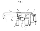
- Fig.1 is the concrete drill 1 mounted with a core bit according to the invention, and boring operation can be carried out by grabbing a grip 2 formed at a rear end of a main body and a sub grip 3 formed on a front side of the main body by the both hands.
- a trigger 4 formed at the grip 2 a motor 5 is driven to rotate to rotate the chuck portion 6 to drive to rotate the core bit 10 mounted to the chuck portion 6.
- a vibration generating mechanism 7 is driven to vibrate a total of the concrete drill 1 to provide vibration along an axial direction to the core bit 10.
- a front end side of the core bit 10 mounted to the chuck portion 6 of the concrete drill 1 is held by a guide member 9 supported by a rod 8 extractable and retractable to and from a front side of the concrete drill 1.
- Cooling water for cooling a front end portion of the core bit 10 in boring is supplied from a side of the concrete drill 1 to the front end portion of the core bit by way of an opening formed at a center of the core bit 10, and cooling water supplied to the front end portion of the core bit 10 is recovered at the guide member 9 arranged to cover a boring face of a concrete wall face or the like and circulated by way of a filtering apparatus or the like via a hose.
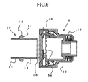
- the core bit 10 is constituted by the drill portion 12 in a shape of a hollow cylinder formed with the boring blade 11 in a cylindrical shape at a front end portion thereof, and the mounting portion 13 in a shape of a hollow cylinder formed at other end side of the drill portion 12, and the drill portion 12 is formed in a dimension and a shape which differ respectively in correspondence with a diameter and a depth of a hole to be bored.
- An end portion of the mounting portion 13 is formed with the guide portion 14 and by mounting the guide portion 14 in a cylindrical shape to the chuck portion 6 of the concrete drill 1, a rotational axis of the concrete drill 1 and a center axis of the core bit 10 are guided to coincide with each other.
- An outer peripheral face of the guide portion 14 remote from an end portion of the mounting portion 13 in a direction of the boring blade 11 is formed with the flange portion 15 in a ring-like shape having an outer diameter larger than an outer diameter of the guide portion 14, and a side face thereof facing other end side of the flange portion 15 in the ring-like shape is formed with the engaging member 16 for transmitting rotation of the chuck portion 6 to the core bit 10.
- the engaging member 16 is formed by a plurality of the engaging projections 17 projected to direct in a direction of the other end side at equal intervals along a circumferential direction at a side face of the flange portion, and rotation on the side of the concrete drill 1 is transmitted to the core bit 10 by engaging the engaging projections 17 with engaging recess portions formed at the chuck portion 6 of the concrete drill 1 as shown in Fig.3.
- a side face of the engaging projection 17 directed in a circumferential direction forms a vertical engaging face 17a
- the engaging projection 17 is contained at inside of the engaging recess portion 6a formed at the chuck portion 6 of the concrete drill 1, and rotation on a side of the concrete drill 1 by way of the engaging recess portion 6a is transmitted to the core bit 10 via the engaging projection 17 of the core bit 10.
- vibration in an axial direction of the concrete drill 1 is transmitted to a side of the core bit 10 by bringing a recess portion 17b formed between the engaging projections 17 in contact with a projected portion 6a formed between the engaging recess portions 6a.
- a lock claw member 18 provided at the chuck portion 6 of the concrete drill 1
- the concrete drill 1 and the core bit 10 are integrally coupled.
- the flange portion 15 having the large diameter is formed at the outer peripheral face of the mounting portion 13 in the cylindrical shape of the core bit 10, a face of the flange portion 15 on a side of an end portion in mounting is formed with the engaging projection 17 projected to the side of the end portion and therefore, the engaging projection 17 exerted with a drive force in a rotational direction from the concrete drill 1 is protected by the outer peripheral edge of the flange portion 15, and the engaging projection 17 can be prevented from being deformed by being brought into contact with other object by dropping or vibrating the core bit 10 in containing or carrying the core bit 10.
- Fig.9 shows the core bit 30 according to other embodiment of the invention, and according to the embodiment, there is shown the core bit capable of being mounted to the chuck portion without changing the shape of the chuck portion of the concrete drill made to be able to mount the core bit shown in the above-described background art.
- the engaging member 16 is formed by forming the locking pieces 32 formed to project to direct to an outer side in a radius direction are formed at an outer peripheral face of the mounting portion 31 formed in a cylindrical shape at equal intervals along a circumferential direction.
- a dimension and an arrangement of the locking pieces 32 are formed to be similar to those of the core bit of the background art.
- an outer peripheral face of the mounting portion 31 in the cylindrical shape remote from the locking piece 32 to a side of the boring blade 35 formed at an end portion of the drill portion 34 is integrally formed with the flange portion 36 in a shape of a flange an outer diameter of which is larger than a height of projecting the locking piece 32.
- the core bit 30 can be mounted to the chuck portion of the concrete drill of the background art, further, in dropping or containing the core bit 30, the locking piece 32 is protected by the outer peripheral edge of the flange portion 36 and therefore, the locking piece 32 can be prevented from being deformed.
- the outer peripheral face of the mounting portion of the core bit formed with the engaging member for transmitting rotation from the side of the concrete drill is formed with the flange portion having the diameter larger than the outer diameter of the engaging member on the side of the boring blade 5 of the engaging member and therefore, dropping the core bit or bringing the engaging member into contact with a concrete face or other object by vibrating the core bit in containing the core bit is protected by the flange portion, it can be prevented that the engaging member is destructed or deformed and cannot be mounted to the chuck portion of the concrete drill or mounted thereto incompletely and operation can be carried out safely.
Landscapes
- Engineering & Computer Science (AREA)
- Mechanical Engineering (AREA)
- Mining & Mineral Resources (AREA)
- Processing Of Stones Or Stones Resemblance Materials (AREA)
- Drilling Tools (AREA)
- Earth Drilling (AREA)
Abstract
Description
Claims (3)
- A core bit for a concrete drill comprising:a drill portion in a cylindrical shape;a boring blade formed at one end side of the drill portion;a mounting portion in a cylindrical shape formed on the other end side of the drill portion;an engaging member formed at an outer peripheral face of the mounting portion; anda flange portion formed at the outer peripheral face of the mounting portion, disposed on a side of the boring blade of the engaging member and having a diameter larger than an outer diameter of the engaging member.
- The core bit for a concrete drill according to Claim 1, wherein the engaging member is formed at a face of the flange portion on a side of an end portion for mounting to the concrete drill, and projects to the side of the end portion.
- The core bit for a concrete drill according to Claim 1, wherein the engaging member comprises a locking piece formed to project from the outer peripheral face of the mounting portion to an outer side in a radius direction.
Applications Claiming Priority (3)
| Application Number | Priority Date | Filing Date | Title |
|---|---|---|---|
| JP2002275427 | 2002-09-20 | ||
| JP2002275427A JP4363019B2 (en) | 2002-09-20 | 2002-09-20 | Core bit |
| PCT/JP2003/011432 WO2004026513A1 (en) | 2002-09-20 | 2003-09-08 | Core bit |
Publications (2)
| Publication Number | Publication Date |
|---|---|
| EP1541267A1 true EP1541267A1 (en) | 2005-06-15 |
| EP1541267A4 EP1541267A4 (en) | 2010-06-02 |
Family
ID=32025031
Family Applications (1)
| Application Number | Title | Priority Date | Filing Date |
|---|---|---|---|
| EP03797553A Withdrawn EP1541267A4 (en) | 2002-09-20 | 2003-09-08 | Core bit |
Country Status (8)
| Country | Link |
|---|---|
| US (1) | US7534076B2 (en) |
| EP (1) | EP1541267A4 (en) |
| JP (1) | JP4363019B2 (en) |
| KR (1) | KR100874520B1 (en) |
| CN (1) | CN1329151C (en) |
| AU (1) | AU2003264391A1 (en) |
| TW (1) | TW200405848A (en) |
| WO (1) | WO2004026513A1 (en) |
Cited By (2)
| Publication number | Priority date | Publication date | Assignee | Title |
|---|---|---|---|---|
| WO2010097223A1 (en) * | 2009-02-25 | 2010-09-02 | Loeschky Tim | Hollow drilling tool comprising an exchangeable drill bit |
| US20150104264A1 (en) * | 2012-03-21 | 2015-04-16 | Hilti Aktiengesellschaft | Drilling tool |
Families Citing this family (15)
| Publication number | Priority date | Publication date | Assignee | Title |
|---|---|---|---|---|
| JP4433721B2 (en) * | 2003-08-07 | 2010-03-17 | マックス株式会社 | Core bit attaching / detaching mechanism such as concrete drill |
| US7938600B1 (en) * | 2006-06-08 | 2011-05-10 | Milwaukee Electric Tool Corporation | Cutting tool and method of operating the same |
| WO2008056399A1 (en) | 2006-11-06 | 2008-05-15 | Kabushiki Kaisha Miyanaga | Shank installation device |
| US9169739B2 (en) | 2012-01-04 | 2015-10-27 | United Technologies Corporation | Hybrid blade outer air seal for gas turbine engine |
| JP5994346B2 (en) * | 2012-04-06 | 2016-09-21 | マックス株式会社 | Bit attachment / detachment mechanism such as concrete drill and drill tool |
| US10088162B2 (en) | 2012-10-01 | 2018-10-02 | United Technologies Corporation | Combustor with grommet having projecting lip |
| EP2886230A1 (en) * | 2013-12-20 | 2015-06-24 | HILTI Aktiengesellschaft | Annular drill bit with a replaceable cutting section |
| EP3213844A1 (en) | 2016-03-03 | 2017-09-06 | HILTI Aktiengesellschaft | Electrical hand-held core drilling machine |
| CN110625822A (en) * | 2019-10-18 | 2019-12-31 | 宜宾天顺商品混凝土有限公司 | A concrete pump pipe drilling device and system |
| EP3834969A1 (en) * | 2019-12-11 | 2021-06-16 | Hilti Aktiengesellschaft | Device for transmitting torque from a drilling device to a drill bit |
| EP3834970A1 (en) | 2019-12-11 | 2021-06-16 | Hilti Aktiengesellschaft | Device for transmitting torque from a drilling device to a drill bit |
| US11623285B2 (en) * | 2021-03-01 | 2023-04-11 | Andrew T. K. Dewberry | Coring device for cutting holes through a structure |
| JP2023107577A (en) * | 2022-01-24 | 2023-08-03 | 株式会社大林組 | Punching device, attachment/detachment method, and core bit |
| CN115488399B (en) * | 2022-10-28 | 2024-09-06 | 浙江欣兴工具股份有限公司 | Quick-dismantling structure, drilling device and quick-dismantling method |
| CN122259277B (en) * | 2026-05-27 | 2026-07-21 | 安徽省(水利部淮河水利委员会)水利科学研究院(安徽省水利工程质量检测中心站) | Automatic centering core machine of concrete dam based on vision positioning |
Family Cites Families (18)
| Publication number | Priority date | Publication date | Assignee | Title |
|---|---|---|---|---|
| US3592554A (en) * | 1968-08-05 | 1971-07-13 | Akio Takahara | Trepan boring tool |
| JPS4940868Y1 (en) * | 1969-12-18 | 1974-11-09 | ||
| US3817648A (en) * | 1971-09-03 | 1974-06-18 | Super Cut | Drill shank and chuck assembly for a drill press |
| JPS5815076Y2 (en) * | 1977-07-18 | 1983-03-26 | 三菱自動車工業株式会社 | Tool mounting device in machine tools |
| JPS5852040Y2 (en) * | 1979-09-10 | 1983-11-28 | 聖和精密工機株式会社 | holder |
| DE3446296A1 (en) * | 1984-12-19 | 1986-06-26 | Maschinenfabrik Reinhausen Gebrüder Scheubeck GmbH & Co KG, 8400 Regensburg | Hollow drill for drilling through GRP laminates |
| DE8513328U1 (en) * | 1985-05-07 | 1985-10-31 | Geißler & Kuper GmbH Diamantwerkzeug - Wiederaufbereitung, 3100 Celle | Diamond core bit with shaft tube and pipe thread connection |
| DK0466702T3 (en) * | 1989-04-05 | 1994-10-10 | Geissler & Kuper Gmbh | Coupler for drill with dust extraction |
| JPH03130338U (en) * | 1990-04-17 | 1991-12-27 | ||
| DE4027820A1 (en) * | 1990-09-01 | 1992-03-05 | Hilti Ag | INSERTION WITH CENTRAL DRILL HOLE |
| JPH0747244B2 (en) * | 1991-02-19 | 1995-05-24 | 株式会社ミヤナガ | Core drill |
| JP2653640B2 (en) * | 1994-09-21 | 1997-09-17 | 株式会社ハウスビーエム | Mounting structure for cylindrical drilling tools |
| DE29503542U1 (en) * | 1995-03-02 | 1995-04-13 | Biedron, Ralf, 44879 Bochum | Drill set with hollow drill for drilling in masonry |
| DE19810911A1 (en) | 1998-03-13 | 1999-09-16 | Hilti Ag | Drilling tool |
| JP3335604B2 (en) * | 1999-08-05 | 2002-10-21 | 株式会社ニコテック | Separable hole saw |
| DE10005365A1 (en) * | 2000-02-07 | 2001-08-09 | Hilti Ag | Core bit |
| JP2002337133A (en) * | 2001-05-16 | 2002-11-27 | Mitsubishi Materials Corp | Drilling device and drilling tool |
| JP3130338U (en) * | 2007-01-11 | 2007-03-22 | 友勁科技股▲ふん▼有限公司 | Flat-symmetric antenna and radio network apparatus having the antenna |
-
2002
- 2002-09-20 JP JP2002275427A patent/JP4363019B2/en not_active Expired - Fee Related
-
2003
- 2003-09-02 TW TW092124179A patent/TW200405848A/en not_active IP Right Cessation
- 2003-09-08 WO PCT/JP2003/011432 patent/WO2004026513A1/en not_active Ceased
- 2003-09-08 US US10/528,233 patent/US7534076B2/en not_active Expired - Fee Related
- 2003-09-08 AU AU2003264391A patent/AU2003264391A1/en not_active Abandoned
- 2003-09-08 KR KR1020057002434A patent/KR100874520B1/en not_active Expired - Fee Related
- 2003-09-08 CN CNB038221292A patent/CN1329151C/en not_active Expired - Fee Related
- 2003-09-08 EP EP03797553A patent/EP1541267A4/en not_active Withdrawn
Cited By (2)
| Publication number | Priority date | Publication date | Assignee | Title |
|---|---|---|---|---|
| WO2010097223A1 (en) * | 2009-02-25 | 2010-09-02 | Loeschky Tim | Hollow drilling tool comprising an exchangeable drill bit |
| US20150104264A1 (en) * | 2012-03-21 | 2015-04-16 | Hilti Aktiengesellschaft | Drilling tool |
Also Published As
| Publication number | Publication date |
|---|---|
| AU2003264391A1 (en) | 2004-04-08 |
| KR100874520B1 (en) | 2008-12-16 |
| JP4363019B2 (en) | 2009-11-11 |
| TW200405848A (en) | 2004-04-16 |
| US20050260048A1 (en) | 2005-11-24 |
| KR20050056970A (en) | 2005-06-16 |
| TWI315697B (en) | 2009-10-11 |
| CN1681615A (en) | 2005-10-12 |
| WO2004026513A1 (en) | 2004-04-01 |
| US7534076B2 (en) | 2009-05-19 |
| CN1329151C (en) | 2007-08-01 |
| JP2004106148A (en) | 2004-04-08 |
| EP1541267A4 (en) | 2010-06-02 |
Similar Documents
| Publication | Publication Date | Title |
|---|---|---|
| US7534076B2 (en) | Core bit | |
| EP1193014B1 (en) | Mandrel assembly for hole saw and drill bit | |
| JP5960367B2 (en) | Drop-in anchor installation tool | |
| JP5032745B2 (en) | Work tools | |
| US20070209814A1 (en) | Power tool | |
| EP0685300A1 (en) | Reversible drill driver tool | |
| US9205548B2 (en) | Impacting tool | |
| AU2018318699B2 (en) | Dust collector for power tool | |
| US5979913A (en) | Universal driving and setting tool and method of using same | |
| CN220903221U (en) | Power tool | |
| US20030051923A1 (en) | Extender assembly for core drill | |
| US20050016333A1 (en) | Power tool, adapter and method of operating the same | |
| US5094330A (en) | Power transmission mechanism with automatic clutch means | |
| JP4433721B2 (en) | Core bit attaching / detaching mechanism such as concrete drill | |
| US7241087B2 (en) | Core bit | |
| JP2004106473A (en) | Core bit removable mechanism in concrete drill or the like | |
| CN1988983A (en) | Receiving device with tool holder and tool holder for machine tools | |
| JP5994346B2 (en) | Bit attachment / detachment mechanism such as concrete drill and drill tool | |
| JPH11199134A (en) | Winding device for wiring harness | |
| JPH10277965A (en) | Dust-proof cap for tool holder | |
| JP7693171B2 (en) | drilling machine | |
| JPH07116998A (en) | Powered rotary impact tool | |
| WO1989001848A1 (en) | Electric power tool and adapter | |
| JPH07552Y2 (en) | Cutting tool for pipe propulsion device | |
| JP2003136312A (en) | Chuck |
Legal Events
| Date | Code | Title | Description |
|---|---|---|---|
| PUAI | Public reference made under article 153(3) epc to a published international application that has entered the european phase |
Free format text: ORIGINAL CODE: 0009012 |
|
| 17P | Request for examination filed |
Effective date: 20050228 |
|
| AK | Designated contracting states |
Kind code of ref document: A1 Designated state(s): AT BE BG CH CY CZ DE DK EE ES FI FR GB GR HU IE IT LI LU MC NL PT RO SE SI SK TR |
|
| AX | Request for extension of the european patent |
Extension state: AL LT LV MK |
|
| DAX | Request for extension of the european patent (deleted) | ||
| RBV | Designated contracting states (corrected) |
Designated state(s): DE FR GB |
|
| A4 | Supplementary search report drawn up and despatched |
Effective date: 20100506 |
|
| RIC1 | Information provided on ipc code assigned before grant |
Ipc: B23B 51/04 20060101AFI20040406BHEP Ipc: B28D 1/14 20060101ALI20100428BHEP Ipc: B28D 1/04 20060101ALI20100428BHEP |
|
| 17Q | First examination report despatched |
Effective date: 20101026 |
|
| 17Q | First examination report despatched |
Effective date: 20101119 |
|
| GRAP | Despatch of communication of intention to grant a patent |
Free format text: ORIGINAL CODE: EPIDOSNIGR1 |
|
| INTG | Intention to grant announced |
Effective date: 20180516 |
|
| RIC1 | Information provided on ipc code assigned before grant |
Ipc: B28D 1/04 20060101ALI20100428BHEP Ipc: B23B 51/04 20060101AFI20040406BHEP Ipc: B28D 1/14 20060101ALI20100428BHEP |
|
| STAA | Information on the status of an ep patent application or granted ep patent |
Free format text: STATUS: THE APPLICATION IS DEEMED TO BE WITHDRAWN |
|
| 18D | Application deemed to be withdrawn |
Effective date: 20180927 |