EP1541108A1 - Movable bed - Google Patents
Movable bed Download PDFInfo
- Publication number
- EP1541108A1 EP1541108A1 EP03797526A EP03797526A EP1541108A1 EP 1541108 A1 EP1541108 A1 EP 1541108A1 EP 03797526 A EP03797526 A EP 03797526A EP 03797526 A EP03797526 A EP 03797526A EP 1541108 A1 EP1541108 A1 EP 1541108A1
- Authority
- EP
- European Patent Office
- Prior art keywords
- bed
- platform
- safety switch
- stage
- adjustable
- Prior art date
- Legal status (The legal status is an assumption and is not a legal conclusion. Google has not performed a legal analysis and makes no representation as to the accuracy of the status listed.)
- Withdrawn
Links
Images




Classifications
-
- A—HUMAN NECESSITIES
- A47—FURNITURE; DOMESTIC ARTICLES OR APPLIANCES; COFFEE MILLS; SPICE MILLS; SUCTION CLEANERS IN GENERAL
- A47C—CHAIRS; SOFAS; BEDS
- A47C19/00—Bedsteads
- A47C19/04—Extensible bedsteads, e.g. with adjustment of length, width, height
- A47C19/045—Extensible bedsteads, e.g. with adjustment of length, width, height with entire frame height or inclination adjustments
-
- A—HUMAN NECESSITIES
- A47—FURNITURE; DOMESTIC ARTICLES OR APPLIANCES; COFFEE MILLS; SPICE MILLS; SUCTION CLEANERS IN GENERAL
- A47C—CHAIRS; SOFAS; BEDS
- A47C20/00—Head-, foot- or like rests for beds, sofas or the like
- A47C20/04—Head-, foot- or like rests for beds, sofas or the like with adjustable inclination
- A47C20/041—Head-, foot- or like rests for beds, sofas or the like with adjustable inclination by electric motors
-
- A—HUMAN NECESSITIES
- A61—MEDICAL OR VETERINARY SCIENCE; HYGIENE
- A61G—TRANSPORT, PERSONAL CONVEYANCES OR ACCOMMODATION SPECIALLY ADAPTED FOR PATIENTS OR DISABLED PERSONS; OPERATING TABLES OR CHAIRS; CHAIRS FOR DENTISTRY; FUNERAL DEVICES
- A61G7/00—Beds specially adapted for nursing; Devices for lifting patients or disabled persons
-
- A—HUMAN NECESSITIES
- A61—MEDICAL OR VETERINARY SCIENCE; HYGIENE
- A61G—TRANSPORT, PERSONAL CONVEYANCES OR ACCOMMODATION SPECIALLY ADAPTED FOR PATIENTS OR DISABLED PERSONS; OPERATING TABLES OR CHAIRS; CHAIRS FOR DENTISTRY; FUNERAL DEVICES
- A61G7/00—Beds specially adapted for nursing; Devices for lifting patients or disabled persons
- A61G7/002—Beds specially adapted for nursing; Devices for lifting patients or disabled persons having adjustable mattress frame
- A61G7/008—Beds specially adapted for nursing; Devices for lifting patients or disabled persons having adjustable mattress frame tiltable around longitudinal axis, e.g. for rolling
-
- A—HUMAN NECESSITIES
- A61—MEDICAL OR VETERINARY SCIENCE; HYGIENE
- A61G—TRANSPORT, PERSONAL CONVEYANCES OR ACCOMMODATION SPECIALLY ADAPTED FOR PATIENTS OR DISABLED PERSONS; OPERATING TABLES OR CHAIRS; CHAIRS FOR DENTISTRY; FUNERAL DEVICES
- A61G7/00—Beds specially adapted for nursing; Devices for lifting patients or disabled persons
- A61G7/002—Beds specially adapted for nursing; Devices for lifting patients or disabled persons having adjustable mattress frame
- A61G7/012—Beds specially adapted for nursing; Devices for lifting patients or disabled persons having adjustable mattress frame raising or lowering of the whole mattress frame
-
- A—HUMAN NECESSITIES
- A61—MEDICAL OR VETERINARY SCIENCE; HYGIENE
- A61G—TRANSPORT, PERSONAL CONVEYANCES OR ACCOMMODATION SPECIALLY ADAPTED FOR PATIENTS OR DISABLED PERSONS; OPERATING TABLES OR CHAIRS; CHAIRS FOR DENTISTRY; FUNERAL DEVICES
- A61G7/00—Beds specially adapted for nursing; Devices for lifting patients or disabled persons
- A61G7/002—Beds specially adapted for nursing; Devices for lifting patients or disabled persons having adjustable mattress frame
- A61G7/015—Beds specially adapted for nursing; Devices for lifting patients or disabled persons having adjustable mattress frame divided into different adjustable sections, e.g. for Gatch position
-
- A—HUMAN NECESSITIES
- A61—MEDICAL OR VETERINARY SCIENCE; HYGIENE
- A61G—TRANSPORT, PERSONAL CONVEYANCES OR ACCOMMODATION SPECIALLY ADAPTED FOR PATIENTS OR DISABLED PERSONS; OPERATING TABLES OR CHAIRS; CHAIRS FOR DENTISTRY; FUNERAL DEVICES
- A61G7/00—Beds specially adapted for nursing; Devices for lifting patients or disabled persons
- A61G7/002—Beds specially adapted for nursing; Devices for lifting patients or disabled persons having adjustable mattress frame
- A61G7/018—Control or drive mechanisms
-
- A—HUMAN NECESSITIES
- A61—MEDICAL OR VETERINARY SCIENCE; HYGIENE
- A61G—TRANSPORT, PERSONAL CONVEYANCES OR ACCOMMODATION SPECIALLY ADAPTED FOR PATIENTS OR DISABLED PERSONS; OPERATING TABLES OR CHAIRS; CHAIRS FOR DENTISTRY; FUNERAL DEVICES
- A61G7/00—Beds specially adapted for nursing; Devices for lifting patients or disabled persons
- A61G7/05—Parts, details or accessories of beds
-
- A—HUMAN NECESSITIES
- A61—MEDICAL OR VETERINARY SCIENCE; HYGIENE
- A61G—TRANSPORT, PERSONAL CONVEYANCES OR ACCOMMODATION SPECIALLY ADAPTED FOR PATIENTS OR DISABLED PERSONS; OPERATING TABLES OR CHAIRS; CHAIRS FOR DENTISTRY; FUNERAL DEVICES
- A61G2203/00—General characteristics of devices
- A61G2203/70—General characteristics of devices with special adaptations, e.g. for safety or comfort
- A61G2203/72—General characteristics of devices with special adaptations, e.g. for safety or comfort for collision prevention
Definitions
- the present invention relates to an adjustable bed for use in nursing care and the like, and particularly to a safety mechanism of the adjustable bed.
- adjustable beds used as postural change assistance beds assist postural changes of a care recipient in order to prevent the occurrence of decubitus ulcers, more commonly known as bedsore.
- bedsore more commonly known as bedsore.
- an adjustable bed tilts at least part of the mattress on which the person is lying at an angle (see Japanese Published Patent Publication No. 6-14824).
- the majority of these types of beds employ a mechanism that tilts the mattress toward one side from a horizontal position.
- a driving mechanism (moving mechanism) for the above adjustable bed is normally provided below a platform of the bed and in an exposed condition. Consequently, there is a danger that a hand of caregivers, care recipients, or their family members gets caught in the moving mechanism. For the sake of safety in operation, the movable bed needs to be improved.
- the present invention is made in view of the above problems, and aims to provide an adjustable bed having a safety mechanism allowing a care giver, a care recipient, and a family member to safely operate the bed.
- an adjustable bed including: amovingmechanismoperable to at least tilt or move up and down a platform of the bed; and a safety switch operable to turn ON and OFF in response to movement of the platform.
- the moving mechanism is suspended when a power ON-OFF state of the safety switch is changed due to displacement of the safety switch from a predetermined position.
- the adjustable bed may further include a changeover member operable, in response to movement of the platform, to change the power ON-OFF state of the safety switch.
- the moving mechanism is made to stop operating upon displacement of the safety switch from the predetermined position.
- the moving mechanism stops operating, before being excessively stressed and damaged.
- the present invention effectively restricts unnecessary accesses to the moving mechanism.
- the present invention provides significantly improved security by immediately suspending the operation of the adjustable bed when a foreign object or a part of human body gets caught in the moving mechanism.
- the adjustable bed may further include a cover disposed so as to cover an outer surface of the moving mechanism.
- the safety switch is disposed at a position determined relative to a position of the cover. The power ON-OFF state of the safety switch is changed upon displacement of the cover from the position.
- the moving mechanism may include: a flexing mechanism operable to flex the platform to form a flexion position that includes at least one of an upper body elevation and a knee flexion; and a tilting mechanism operable to laterally tilt the platform.
- the flexing and tilting mechanisms are each operable when the other mechanism is operating.
- the cover is mounted to the tilting mechanism.
- the adjustable bed may further include: a side member disposed on a side of the platform, and a side member raising mechanism for raising the side member relative to the platform.
- the tilting mechanism downwardly tilts the platform toward the side member raised by the side member raising mechanism.
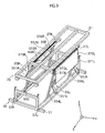
- FIG. 1 is an oblique view showing the overall structure of an adjustable bed 1 according to the embodiment 1 of the present invention.
- the bed 1 shown in the figure is constituted such that a bed frame 10 is placed on an adjustable stage 20 which in turn is placed on a fixed stage 30.
- the bed frame 10 has a surface area that is composed of four platform members 11a-11d for suitably receiving four articulations (the upper body, lower body, upper leg, and lower leg regions) of the care recipient' s body when lying on the bed.
- the four platform members 11a-11d are movably coupled to constitute a coupled platform. More specifically, the bed frame 10 is composed of an upper-body member 11a, a lower-back member 11b, an upper-leg member 11c, and a lower-leg member 11d coupled in the stated order.
- the lower-back member 11b is directly secured to the adjustable stage 20 by welding, for example.
- the platform members 11a-11d are each flanked by respective pairs of side members 12Ra-12Rd and 12La-12Ld coupled thereto from the right and left.
- the side members 12Ra-12Rd and 12La-12Ld support the care recipient' s body from the side at the time of postural change.
- the upper-body member 11a of the bed frame 10 is coupled to the shaft of a direct-acting actuator M1 via an L-shaped coupler 211, whereas the upper-leg member 11c is coupled to the shaft of a direct-acting actuator M2 via an L-shaped coupler 212.
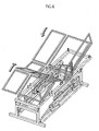
- the actuators M1 and M2 are disposed on a center beam 21A of the adjustable stage 20. (See FIG. 3 showing a top view of the bed.) Thus, by the action of the actuators M1 and M2, the bed' s profile is adjusted to bring the care recipient into a flexion posture (see FIG. 6 showing a state of the bed and FIG. 8B showing a side view of the bed).
- each of the platform members 11a-11d as well as the side members 12Ra-12Rd and 12La-12Ld are covered by wire mesh.
- the wire mesh is omitted to show the frames of the platform members 11a-11d and of the side members 12Ra-12Rd and 12La-12Ld in order to clearly illustrate the structure and operation of the bed.
- the fixed stage 30 is provided with mechanics covers 370R and 370L serving as a safety mechanism, the mechanics covers 370R and 370L are shown in FIGs. 9 and onward.
- FIGs. 6-8 showing bed operations in addition, some of the constituent elements, such as side-member support frames 24R and 24L, are omitted so as to clearly illustrate the bed operations.
- the side members 12Rc and 12Lc are located at positions corresponding to the upper-legs of the care recipient.
- the side members 12Rc and 12Lc are each provided, on the surface, with an envelope-like pocket that is approximately the same size as the side members 12Rc and 12Lc (see FIG. 8D showing a side view of the bed).
- the side members 12Rd and 12Ld located at positions corresponding to the lower-legs of the care recipient are coupled, along the edge, to fan-shaped members 13R and 13L, respectively (13R is not illustrated).
- the fan-shaped members 13R and 13L are housed in the above-mentioned pockets of the side members 12Rc and 12Lc.
- the fan-shaped members 13R and 13L come out of the pockets to support the care recipient's knees.
- the adjustable stage 20 has a rectangular frame construction formed from the center beam 21A, side beams 21R and 21L, and two parallel frames each connecting the respective ends of the center and side beams.
- the side beams 21R and 21L are provided with rollers 200, 201, 202, and 203 allowing sliding movement of the side beams 21R and 21L along a roller slide frame 300 in the direction of y (the roller 203 is hidden beneath the bed frame 10).
- the side beam 21R of the adjustable stage 20 is provided with a pair of bars 22R and 23R extending along the side beam 21R, as well as with connecting bars 231R and 232R.
- the pair of bars 22R and 23R and the connecting bars 231R and 232R together constitute a ladder-like side-member support frame 24R.
- the side beam 21L is provided with a ladder-like side-member support frame 24L constituted of a pair of bars 22L and 23L extending along the side frame 21L, as well as of connecting bars 231L and 232L.
- the bars 22R, 23R, 22L, and 23L each have bends defining a concave along its lengthwise direction.
- the concaves are formed at positions where the side members 12Rb and 12Lb engage against the side-member support frames 24R and 24L, respectively. Consequently, the side member 12Rb fits within the concave (see FIG. 3 showing the top view of bed). Being fit within the respective concaves, the side members 12Rb and 12Lb obstruct neither the side members 12Ra and 12La nor the side members 12Rc and 12Lc in the thickness directions even when bed frame 10 is adjusted to the flexion position.
- the bar 22R is coupled to the side beam 21R by couplers 236Ra and 236Rb
- the bar 22L is coupled to the side beam 21L by couplers 236La and 236Lb.
- the bars 22R and 22L are allowed to freely rotate on their axes while remaining secured to the side beams 21R and 21L.
- the side-member support frames 24R and 24L By rotating the side-member support frames 24R and 24L on the axes of the rotating bars 22R and 22L to a vertical position (in the z direction), the side members 12Ra-12Rd and 12La-12Ld are pushed upward to a risen position.
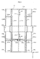
- FIGs. 2A-2C are schematic sectional views of the adjustable stage 20 and the bed frame 10, taken laterally across the lower-back member 11c to illustrate the operations of the actuators.
- the adjustable stage 20 is provided with the above-described actuators M1 and M2 for changing the profile of the bed frame 10.
- the adjustable stage 20 is provided with direct-acting actuators M3R andM3L disposed in laterally symmetric relation to the center beam 21A.
- the actuators M3R and M3L are disposed on the right and left of the y direction correspondingly to the couplers 236Ra and 236La.
- each shaft of the actuators M3R and M3L is respectively coupled to the L-shaped members 235R and 235L, which are hung from the respective rotating bars 22R and 22L.
- the L-shaped members 235R and 235L and the bars 23R and 23L rotate on the rotating bars 22R and 22L.
- the side-member support frames 24R and 24L rise from the horizontal surface of the bed to form a right angle with respect to the bed surface (FIGs. 2A ⁇ 2B ⁇ 2C).
- stage bars 27R and 27L are provided on the underside of the side beams 21R and 21L.
- stage-bar receives 36R and 36L On the fixed stage 30 are provided stage-bar receives 36R and 36L having a U-shaped cross section to receive the stage bars 27R and 27L, respectively.
- Reverse L-shape pawls are disposed inside each of the stage-bar bearings 36R and 36L along the width-wise direction. The pawls engage around the stage bars 27R and 27L received in the stage-bar bearings 36R and 36L, so that the adjustable stage 20 is fixed against the vertical movement. Yet, when the adjustable stage 20 is tilted, one of the stage bars 27R and 27L are lifted and detached from the respective one of the stage-bar bearings 36R and 36L.
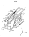
- FIG. 4 is an oblique view of the fixed stage 30.
- the fixed stage 30 is provided with a rectangular frame 31.
- One of a pair of shorter opposite sides of the rectangular frame 31 constitutes the roller slide frame 300 along which the rollers 200-203 of the adjustable stage 20 slide back and forth.
- Side beams 32R and 32L of the fixed stage 30 constitute sliding channels substantially defining a laterally oriented U-shape in cross section with their openings facing each other.
- Support arms 354R and 356R are both coupled at one end to the stage-bar bearings 36R, and to the side beam 32R at the other end in a manner freely slidable along the side beam 32R.
- support arms 354L and 356L are both coupled at one end to the stage-bar bearing 36L, and to the side beam 32L at the other end in a manner freely slidable along the side beam 32L.
- the support arms 354R, 356R, 354L, and 356L are separately linked to reverse L-shaped rotating arms 351R, 352R, 351L, and 352L.
- the rotating arms 351R, 352R, 351L, and 352L are coupled at one end to the side beams 32R and 32L, and also to horizontal links 353R and 353L the other end.
- An actuator M4R is disposed at an angle between the stage-bar bearing 36R and the horizontal link 353R.
- an actuator M4L is disposed at an angle between the stage-bar bearing 36L and the horizontal link 353L.
- parallelogram mechanisms 35R and 35L are constituted one on each lateral side of the fixed stage 30.
- the rotating arms 351R, 352R, 351L, and 352L make a circular motion about the linked points on the side beams 32R and 32L.
- the ends of the support arms 354R, 356R, 354L, and 356L move back and forth within the grooves of the side beams 32R and 32L.
- the adjustable stage 20 as well as the bed frame 10 supported by the stage-bar bearings 36R and 36L vertically moves away from or toward the right and left sides of fixed stage 30. That is to say, the bed 1 is capable of up and down movement within a narrow space and is of a space-saving configuration.
- the rollers 200-203 and the parallelogram mechanisms 35R and 35L enable the postural change operations without requiring much space.
- the bed 1 By driving one of the parallelogram mechanisms 35R and 35L at a time for the movement of either of the side beams 32R and 32L, the bed 1 is adjusted its profile for the postural change from a supine posture to a lateral side-lying posture. On the other hand, driving both the parallelogram mechanisms 35R and 35L at the same time, the High/Low operation of the bed 1 is carried out.
- the drive of the actuators M1, M2, M3R, andM3L are controlled by a motor driver 403 and a CPU 401 provided with in a control unit 400, all of which are described later.
- the drive setting including pre-programming may be made automatically or manually by the caregiver using a controller (not illustrated) at hand. Furthermore, with the use of a remote controller of an infrared, wired, or wireless type, the drive setting may be made by the care recipient.
- the structure of the adjustable bed 1 described above 1 is one example.
- the mechanics covers 370R and 370L which are a feature of the present invention, may be applied to an adjustable bed having a different structure.
- the adjustable bed having the above structure is put to actual use with a mattress overlaid on the bed frame 10.
- the detailed description of the mattress is described later in detail.
- the platform members 11a-11d and the side members 12Ra-12Rd and 12La-12Ld are all disposed substantially horizontal and together constitute a bed surface, as shown in FIG. 1.
- a user selects and executes on the controller a menu for a postural change from a supine and flexion posture to a left side-lying and flexion posture.
- the actuator M3L attached to the adjustable stage 20 is activated and extends its shaft.
- the bar 23L and the L-shaped member 235L coupled to the end of the shaft rotate about the rotating bar 22L.
- the side-member support frame 24L comes to rise and form a right angle with respect to the horizontal bed surface.
- the direct-acting actuators M1 and M2 attached to the center beam 21A of the adjustable stage 20 extend their shafts, thereby separately pushing, via the L-shaped couplers 211 and 212, the upper-body member 11a and the lower-back member 11c of the bed frame 10 from the rear.
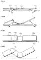
- the bed is adjusted to a position for the care recipient to be in a flexion posture with the upper body raised and the knees up (see FIG. 6 showing an oblique view of the bed in the flexion position; and FIGs. 8A ⁇ 8B showing side views of the bed in this state).
- the side members 12La-12Ld also change their positions accordingly.
- the fan-shaped members 13L comes out from the pocket of the side member 12Lc to support parts of the mattress around the care recipient' s knees (see FIGs. 8C ⁇ 8D showing side views of the bed in this state).
- the actuator M4R disposed on the side beam 32R of the fixed stage 30 then extends its shaft to widen the distance between the stage-bar bearing 36R and the horizontal link 353R.
- the support arms 354R and 356R slide in the sliding groove of the side beam 32R to a more upright position.
- the parallelogram mechanism 35R works.
- the two support arms 354R and 356R or 354L and 356L come to vertically lift the right side of the adjustable stage 20 in response to the circular motion of the two rotating arms 351R and 352R or 351L and 352L.
- the right side of the adjustable stage 20 is vertically lifted to a level higher than the fixed stage 30, thereby causing the rollers 201-204 to run on the roller slide frame 300. Consequently, the bed frame 10 downwardly inclines toward the side beam 32L of the fixed stage 30, i.e. toward the left side of the bed (see FIG. 7 showing the bed in the inclined state).
- the inclination angle of the bed to the horizontal surface falls within the range of about 30° to 70°, for example about 50°.
- the care recipient is assisted to smoothly change the posture from a supine to a lateral position while being supported by the platform members 11a-11d and the side members 12La-12Ld, after firstly being placed in a supine flexion position with the upper body raised and the knees flexed.
- the above postural change is smoothly carried out as if the care recipient' body rolls along the hands of caregiver put to support the care recipient.
- FIG. 9 is a view showing the adjustable bed provided with a safety mechanism. More specifically, the figure shows the structure around the fixed stage of the bed.
- the parallelogram mechanisms 35R and 35L are provided with the mechanics cover 370R and 370L, respectively.
- Each mechanics cover is shaped like a plate and covers the respective parallelogram mechanism from outside.
- each of the mechanics covers 370R and 370L is made of a styrene board.
- the mechanics cover 370R is attached to the stage-bar bearing 36R by engagement between U-shaped metal pieces 372R and 373R (not illustrated).
- the mechanics cover 370L is attached to the stage-bar bearing 3 6L by engagement between U-shapedmetal pieces 372L and 373L.
- the mechanics covers 370R and 370L are hung upon the respective stage-bar bearings 36R and 36L along the lengthwise direction.
- a safety switch is provided between each pair of engaging metal pieces 372R and 373R as well as 372L and 372R.
- micro switches MSR and MSL are disposed between the respective pairs of metal pieces.
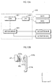
- the state of the micro switches MSR and MSL (SW R and SW L) is monitored by the CPU 401 via the I/O 402 of the control unit 400.
- the micro switches MSR and MSL are in ON state under the weight of the mechanics covers 370R and 370L.
- any foreignobject an armof the caregiver, for example
- lifts either of the mechanics covers 370R and 370L from underneath a corresponding one of the metal piece pairs is disengaged.
- the CPU 401 of the control unit 400 stops the drive of the actuators M4R and M4L in the parallelogram mechanisms 35R and 35L.
- the mechanics covers 370R and 370L function as elements triggering the ON/OFF state changeover of the micro switches MSR and MSL.
- the actuators M1 and M2 which are driven to change the bed to a Gatch position, are also made to stop.
- the micro switches MSR and MSL are employed in this example, other types of switches are applicable, including a push switch, a lever switch, and a slide switch.
- the drive of the bed is immediately suspended in the case where the caregiver, care recipient, or family member accidentally places his hand in or around the parallelogram mechanisms while the bed is being driven. It is because when either of the mechanics covers 370R and 370L is lifted as a result of a contact with the hand, the pair of U-shapedmetal pieces 372R and 373R or 372L and 373L is disengaged.
- the adjustable bed ensures significantly improved safety.
- the provision of the mechanics covers 370R and 370L offers a safety measurement to prevent that the caregiver, the care recipient, or a family member accidentally places a part of the body (a limb, for example) inside the bed to reach the moving parts, such as the parallelogram mechanisms 35R and 35L.
- the provision of the mechanics covers 370R and 370L serves to hide the moving parts, such as the parallelogram mechanisms 35R and 35L, from view.
- the present invention is not limited to the above configuration of suspending the drive of the bed upon disengagement of the pair of U-shaped metal pieces 372R and 373R or 372L and 373L.
- the present invention may be configured so as to switch off the drive of the parallelogram mechanisms 35R and 35L based on the detection signal from the micro switches, at the time when the pair of U-shaped metal pieces is lifted.
- the present invention is not limited to the configuration employing the U-shaped metal pieces 372R, 373R, 372L, and 373L. Any configuration is applicable as long as the displacement of mechanics covers from the predetermined positions (where the mechanics covers are normally hung on) is detected, and the parallelogram mechanisms 35R and 35L are switched off in response to the detection signal.
- the mechanics covers 370R and 370L cover the parallelogram mechanisms 35R and 35L, as shown in FIG. 9.
- the mechanics covers 370R and 370L may be as large in lengthwise as the adjustable stage 20 in the direction X.
- the above description is directed to the example in which the mechanics covers composed of styrene boards are disposed to cover the moving parts including the parallelogram mechanisms 35R and 35L from outside.
- the mechanics covers 370R and 370L may be composed of metallic or plastic frames (the overall size of the frames is preferably equal to the mechanics covers 370R and 370L as in the above example).
- a lattice or a plate made of a translucent resin may be applicable.
- the material and configuration of the mechanics covers 370R and 370L may be suitably altered.
- the above example is directed to the case where the micro switches MSR and MSL are arranged between the pairs of the U-shaped metal pieces 372R and 372L as well as 373L and 373R that in turn arranged at the upper part of the parallelogram mechanisms 35R and 35L.
- the micro switches MSR and MSL may be arranged on any of the following elements 353R and 353L, 354R and 354L and 356R and 356L.
- the micro switches MSR and MSL may be each provided with a pole-like member or wire-like member as the triggering mechanism used in conjunction with, for example, the above-described U-shape metal pieces.
- the above embodiment 1 is directed to the bed structure employing the parallelogram mechanisms. Yet, the present invention is not limited to such a structure, and the adjustable bed may be of another structure as follows.
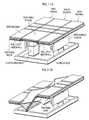
- An adjustable bed shown in FIG. 11A is provided with vertically disposed direct-acting actuators. Using elevating mechanisms, either of left and right side members is moved up or down, thereby inclining a platform placed on an adjustable stage.
- the bed is provided with a rectangular frame serving as a fixed stage, and a pair of direct-acting actuators having columnar shape. On the top of the actuators is provided a bed frame supported by a flexible frame.
- the platform of the bed is constituted by coupling a plurality of platform members, so as to receive the upper body, lower back, upper leg, and lower leg regions of the care recipient's body.
- the one receiving the lower back of the care recipient's body is securely fixed to the platform frame serving as the movable frame.
- a driving unit for driving an actuator mechanism used to change the bed to a flexion position.
- the mechanics covers serving as a safety mechanism according to the present invention are disposed along a lateral side of each columnar actuator.
- side members of the bed are disposed on the top of the columnar actuators.
- the side members each have a housing slot formed therein, and a pullout wall is housed in each housing slot.
- the pullout walls are coupled to each other along a lengthwise direction of the bed.
- the side members are coupled to the adjustable stage via the respective pullout walls.
- Each pullout wall is biased toward inside the housing slot by a tension spring, for example. When the force puling out the pullout walls weakens, the pullout walls are automatically retracted back into the housing slots.
- the coupledplatform is first changed its profile to a flexion position, as shown in FIG. 11B. Then, one of the columnar actuators starts operating to descend either right or left side members. As a result, the adjustable stage, as well as the coupled platform, is laterally inclined. On the downwardly inclined lateral side of the adjustable stage, the pullout walls are pulled out from the housing slots to rise relatively to the coupled platform. In other words, the pullout walls are hung from the coupled platform so as to form a smaller angle therebetween. Correspondingly to the above profile change, the side members come to rise relative to the surface of the platform.
- the care recipient is suitably supported from the side by the pullout walls while in a flexion posture, thereby assisting the postural change as effectively as the embodiment 1.
- the mechanics covers operate just as in the embodiment 1 and provide a suitable safety mechanism.
- the micro switches are normally ON, and turned OFF upon detection of a foreign object.
- the present invention is not limited to the above structure.
- the micro switches may be normally OFF, and turned ON upon detection of a foreign object.
- the ON/OFF state of the micro switches may be adapted to either way, depending on the circuitry configuration.
- the CPU 401 controls the drive of the actuators.
- the drive control may be carried out without a CPU through the hardware structure (for example, a structure that interrupts the power supply to the driving systems such as the actuators when any of the micro switches are tuned OFF)
- the adjustable bed according to the present invention is suitably used as a nursing care bed or a reclining bed.
Landscapes
- Health & Medical Sciences (AREA)
- Nursing (AREA)
- General Health & Medical Sciences (AREA)
- Life Sciences & Earth Sciences (AREA)
- Animal Behavior & Ethology (AREA)
- Public Health (AREA)
- Veterinary Medicine (AREA)
- Invalid Beds And Related Equipment (AREA)
Abstract
An adjustable bed includes a moving mechanism operable to
at least tilt or move up and down a platform of the bed, and
a safety switch operable to turn ON and OFF in response to movement
of the platform. The moving mechanism is suspended when a power
ON-OFF state of the safety switch is changed due to displacement
of the safety switch from a predetermined position. In addition,
a cover may be disposed over the moving mechanism from an outer
surface. The safety switch is disposed at a position determined
relative to a position of the cover. The power ON-OFF state
of the safety switch is changed upon displacement of the cover
from the position.
Description
The present invention relates to an adjustable bed for use
in nursing care and the like, and particularly to a safety
mechanism of the adjustable bed.
Generally, adjustable beds used as postural change
assistance beds assist postural changes of a care recipient in
order to prevent the occurrence of decubitus ulcers, more
commonly known as bedsore. To this end, such an adjustable bed
tilts at least part of the mattress on which the person is lying
at an angle (see Japanese Published Patent Publication No.
6-14824). The majority of these types of beds employ a mechanism
that tilts the mattress toward one side from a horizontal
position.
A driving mechanism (moving mechanism) for the above
adjustable bed is normally provided below a platform of the bed
and in an exposed condition. Consequently, there is a danger
that a hand of caregivers, care recipients, or their family
members gets caught in the moving mechanism. For the sake of
safety in operation, the movable bed needs to be improved.
The present invention is made in view of the above problems,
and aims to provide an adjustable bed having a safety mechanism
allowing a care giver, a care recipient, and a family member
to safely operate the bed.
To address the above problems, the present invention
provides an adjustable bed including: amovingmechanismoperable
to at least tilt or move up and down a platform of the bed; and
a safety switch operable to turn ON and OFF in response to movement
of the platform. The moving mechanism is suspended when a power
ON-OFF state of the safety switch is changed due to displacement
of the safety switch from a predetermined position.
Specifically, the adjustable bed may further include a
changeover member operable, in response to movement of the
platform, to change the power ON-OFF state of the safety switch.
With the adjustable bed having the above structure, first
of all, the moving mechanism is made to stop operating upon
displacement of the safety switch from the predetermined position.
Thus, in the case where a foreign object or a part of human body
gets caught in the moving mechanism, the moving mechanism stops
operating, before being excessively stressed and damaged. As
described above, the present invention effectively restricts
unnecessary accesses to the moving mechanism. In addition, the
present invention provides significantly improved security by
immediately suspending the operation of the adjustable bed when
a foreign object or a part of human body gets caught in the moving
mechanism.
Second of all, the immediate suspension of the bed operation
achieves the effect of preventing an excessive stress to the
moving mechanism.
Specifically, the adjustable bed may further include a cover
disposed so as to cover an outer surface of the moving mechanism.
The safety switch is disposed at a position determined relative
to a position of the cover. The power ON-OFF state of the safety
switch is changed upon displacement of the cover from the
position.
Further, the moving mechanism may include: a flexing
mechanism operable to flex the platform to form a flexion position
that includes at least one of an upper body elevation and a knee
flexion; and a tilting mechanism operable to laterally tilt
the platform. The flexing and tilting mechanisms are each
operable when the other mechanism is operating. The cover is
mounted to the tilting mechanism.
Still further, the adjustable bed may further include: a
side member disposed on a side of the platform, and a side member
raising mechanism for raising the side member relative to the
platform. The tilting mechanism downwardly tilts the platform
toward the side member raised by the side member raising
mechanism.
Hereinafter, a description is first given to the overall
structure of an adjustable bed according to an embodiment 1 of
the present invention. Then, a detailed description is given
to the safety mechanism (utilizing a mechanics cover) of the
bed.
FIG. 1 is an oblique view showing the overall structure
of an adjustable bed 1 according to the embodiment 1 of the present
invention.
The bed 1 shown in the figure is constituted such that a
bed frame 10 is placed on an adjustable stage 20 which in turn
is placed on a fixed stage 30.
The bed frame 10 has a surface area that is composed of
four platform members 11a-11d for suitably receiving four
articulations (the upper body, lower body, upper leg, and lower
leg regions) of the care recipient' s body when lying on the bed.
The four platform members 11a-11d are movably coupled to
constitute a coupled platform. More specifically, the bed frame
10 is composed of an upper-body member 11a, a lower-back member
11b, an upper-leg member 11c, and a lower-leg member 11d coupled
in the stated order.
The lower-back member 11b is directly secured to the
adjustable stage 20 by welding, for example. Thus, the bed frame
10 is not detachable from the adjustable stage 20. The platform
members 11a-11d are each flanked by respective pairs of side
members 12Ra-12Rd and 12La-12Ld coupled thereto from the right
and left. The side members 12Ra-12Rd and 12La-12Ld support the
care recipient' s body from the side at the time of postural change.
The upper-body member 11a of the bed frame 10 is coupled to the
shaft of a direct-acting actuator M1 via an L-shaped coupler
211, whereas the upper-leg member 11c is coupled to the shaft
of a direct-acting actuator M2 via an L-shaped coupler 212. The
actuators M1 and M2 are disposed on a center beam 21A of the
adjustable stage 20. (See FIG. 3 showing a top view of the bed.)
Thus, by the action of the actuators M1 and M2, the bed' s profile
is adjusted to bring the care recipient into a flexion posture
(see FIG. 6 showing a state of the bed and FIG. 8B showing a
side view of the bed).
Note that each of the platform members 11a-11d as well as
the side members 12Ra-12Rd and 12La-12Ld are covered by wire
mesh. In the drawings, however, the wire mesh is omitted to
show the frames of the platform members 11a-11d and of the side
members 12Ra-12Rd and 12La-12Ld in order to clearly illustrate
the structure and operation of the bed. In addition, although
the fixed stage 30 is provided with mechanics covers 370R and
370L serving as a safety mechanism, the mechanics covers 370R
and 370L are shown in FIGs. 9 and onward. In FIGs. 6-8 showing
bed operations, in addition, some of the constituent elements,
such as side-member support frames 24R and 24L, are omitted so
as to clearly illustrate the bed operations.
As mentioned above, among the side members 12Ra-12Rd and
12La-12Ld, the side members 12Rc and 12Lc are located at positions
corresponding to the upper-legs of the care recipient. The side
members 12Rc and 12Lc are each provided, on the surface, with
an envelope-like pocket that is approximately the same size as
the side members 12Rc and 12Lc (see FIG. 8D showing a side view
of the bed). In addition, the side members 12Rd and 12Ld located
at positions corresponding to the lower-legs of the care
recipient are coupled, along the edge, to fan-shaped members
13R and 13L, respectively (13R is not illustrated). Normally,
the fan-shaped members 13R and 13L are housed in the
above-mentioned pockets of the side members 12Rc and 12Lc. When
the bed frame 10 is adjusted to a position for the flexion posture,
the fan-shaped members 13R and 13L come out of the pockets to
support the care recipient's knees.
The adjustable stage 20 has a rectangular frame construction
formed from the center beam 21A, side beams 21R and 21L, and
two parallel frames each connecting the respective ends of the
center and side beams. As illustrated in the figures, the side
beams 21R and 21L are provided with rollers 200, 201, 202, and
203 allowing sliding movement of the side beams 21R and 21L along
a roller slide frame 300 in the direction of y (the roller 203
is hidden beneath the bed frame 10).
The side beam 21R of the adjustable stage 20 is provided
with a pair of bars 22R and 23R extending along the side beam
21R, as well as with connecting bars 231R and 232R. The pair
of bars 22R and 23R and the connecting bars 231R and 232R together
constitute a ladder-like side-member support frame 24R.
Similarly, the side beam 21L is provided with a ladder-like
side-member support frame 24L constituted of a pair of bars 22L
and 23L extending along the side frame 21L, as well as of connecting
bars 231L and 232L. The bars 22R, 23R, 22L, and 23L each have
bends defining a concave along its lengthwise direction. The
concaves are formed at positions where the side members 12Rb
and 12Lb engage against the side-member support frames 24R and
24L, respectively. Consequently, the side member 12Rb fits
within the concave (see FIG. 3 showing the top view of bed).
Being fit within the respective concaves, the side members 12Rb
and 12Lb obstruct neither the side members 12Ra and 12La nor
the side members 12Rc and 12Lc in the thickness directions even
when bed frame 10 is adjusted to the flexion position. In
addition, the bar 22R is coupled to the side beam 21R by couplers
236Ra and 236Rb, and the bar 22L is coupled to the side beam
21L by couplers 236La and 236Lb. Owing to the coupling to the
side beams 21R and 21L, the bars 22R and 22L are allowed to freely
rotate on their axes while remaining secured to the side beams
21R and 21L. By rotating the side-member support frames 24R
and 24L on the axes of the rotating bars 22R and 22L to a vertical
position (in the z direction), the side members 12Ra-12Rd and
12La-12Ld are pushed upward to a risen position.
FIGs. 2A-2C are schematic sectional views of the adjustable
stage 20 and the bed frame 10, taken laterally across the
lower-back member 11c to illustrate the operations of the
actuators. As shown in the figures, the adjustable stage 20
is provided with the above-described actuators M1 and M2 for
changing the profile of the bed frame 10. In addition, the
adjustable stage 20 is provided with direct-acting actuators
M3R andM3L disposed in laterally symmetric relation to the center
beam 21A. Specifically, the actuators M3R and M3L are disposed
on the right and left of the y direction correspondingly to the
couplers 236Ra and 236La. The end of each shaft of the actuators
M3R and M3L is respectively coupled to the L-shaped members 235R
and 235L, which are hung from the respective rotating bars 22R
and 22L. With this structure, when the shaft of each of the
actuators M3R and M3L extends, the L-shaped members 235R and
235L and the bars 23R and 23L rotate on the rotating bars 22R
and 22L. As a result, the side-member support frames 24R and
24L rise from the horizontal surface of the bed to form a right
angle with respect to the bed surface (FIGs. 2A → 2B → 2C).
On the underside of the side beams 21R and 21L, stage bars
27R and 27L are provided. On the fixed stage 30 are provided
stage-bar receives 36R and 36L having a U-shaped cross section
to receive the stage bars 27R and 27L, respectively. Reverse
L-shape pawls are disposed inside each of the stage- bar bearings
36R and 36L along the width-wise direction. The pawls engage
around the stage bars 27R and 27L received in the stage- bar
bearings 36R and 36L, so that the adjustable stage 20 is fixed
against the vertical movement. Yet, when the adjustable stage
20 is tilted, one of the stage bars 27R and 27L are lifted and
detached from the respective one of the stage- bar bearings 36R
and 36L.
FIG. 4 is an oblique view of the fixed stage 30. The fixed
stage 30 is provided with a rectangular frame 31. One of a pair
of shorter opposite sides of the rectangular frame 31 constitutes
the roller slide frame 300 along which the rollers 200-203 of
the adjustable stage 20 slide back and forth. Side beams 32R
and 32L of the fixed stage 30 constitute sliding channels
substantially defining a laterally oriented U-shape in cross
section with their openings facing each other. Support arms
354R and 356R are both coupled at one end to the stage-bar bearings
36R, and to the side beam 32R at the other end in a manner freely
slidable along the side beam 32R. Similarly, support arms 354L
and 356L are both coupled at one end to the stage-bar bearing
36L, and to the side beam 32L at the other end in a manner freely
slidable along the side beam 32L. In addition, the support arms
354R, 356R, 354L, and 356L are separately linked to reverse
L-shaped rotating arms 351R, 352R, 351L, and 352L. The rotating
arms 351R, 352R, 351L, and 352L are coupled at one end to the
side beams 32R and 32L, and also to horizontal links 353R and
353L the other end. An actuator M4R is disposed at an angle
between the stage-bar bearing 36R and the horizontal link 353R.
Similarly, an actuator M4L is disposed at an angle between the
stage-bar bearing 36L and the horizontal link 353L. With the
above arrangement, parallelogram mechanisms 35R and 35L are
constituted one on each lateral side of the fixed stage 30. With
parallelogram mechanisms 35R and 35L employing a horizontal
sliding mechanism, the rotating arms 351R, 352R, 351L, and 352L
make a circular motion about the linked points on the side beams
32R and 32L. In response to the circular motion of the rotating
arms 351R, 352R, 351L, and 352L, the ends of the support arms
354R, 356R, 354L, and 356L move back and forth within the grooves
of the side beams 32R and 32L. When the support arms 354R, 356R,
354L, and 356L swing toward a vertical position, the adjustable
stage 20 as well as the bed frame 10 supported by the stage- bar
bearings 36R and 36L vertically moves away from or toward the
right and left sides of fixed stage 30. That is to say, the
bed 1 is capable of up and down movement within a narrow space
and is of a space-saving configuration. In addition, the rollers
200-203 and the parallelogram mechanisms 35R and 35L enable the
postural change operations without requiring much space. By
driving one of the parallelogram mechanisms 35R and 35L at a
time for the movement of either of the side beams 32R and 32L,
the bed 1 is adjusted its profile for the postural change from
a supine posture to a lateral side-lying posture. On the other
hand, driving both the parallelogram mechanisms 35R and 35L at
the same time, the High/Low operation of the bed 1 is carried
out.
The drive of the actuators M1, M2, M3R, andM3L are controlled
by a motor driver 403 and a CPU 401 provided with in a control
unit 400, all of which are described later. The drive setting
including pre-programming may be made automatically or manually
by the caregiver using a controller (not illustrated) at hand.
Furthermore, with the use of a remote controller of an infrared,
wired, or wireless type, the drive setting may be made by the
care recipient.
Note that the structure of the adjustable bed 1 described
above 1 is one example. As later described, the mechanics covers
370R and 370L, which are a feature of the present invention,
may be applied to an adjustable bed having a different structure.
The adjustable bed having the above structure is put to
actual use with a mattress overlaid on the bed frame 10. The
detailed description of the mattress is described later in detail.
In the normal profile, the platform members 11a-11d and the side
members 12Ra-12Rd and 12La-12Ld are all disposed substantially
horizontal and together constitute a bed surface, as shown in
FIG. 1.
First, a user (caregiver, in this example) selects and
executes on the controller a menu for a postural change from
a supine and flexion posture to a left side-lying and flexion
posture. In response, the actuator M3L attached to the
adjustable stage 20 is activated and extends its shaft. Then,
the bar 23L and the L-shaped member 235L coupled to the end of
the shaft rotate about the rotating bar 22L. As a result, the
side-member support frame 24L comes to rise and form a right
angle with respect to the horizontal bed surface. (See FIGs.
2A → 2B → 2C illustrating the actuator operations; FIG. 5 showing
the state of the side members 12La-12Ld in a raised state; and
FIG. 8C showing the side view of the bed in the raised state).
Next, the direct-acting actuators M1 and M2 attached to
the center beam 21A of the adjustable stage 20 extend their shafts,
thereby separately pushing, via the L-shaped couplers 211 and
212, the upper-body member 11a and the lower-back member 11c
of the bed frame 10 from the rear. As a result, the bed is adjusted
to a position for the care recipient to be in a flexion posture
with the upper body raised and the knees up (see FIG. 6 showing
an oblique view of the bed in the flexion position; and FIGs.
8A → 8B showing side views of the bed in this state). With the
positional change of the platform members 11a-11d, the side
members 12La-12Ld also change their positions accordingly. As
a result, the fan-shaped members 13L comes out from the pocket
of the side member 12Lc to support parts of the mattress around
the care recipient' s knees (see FIGs. 8C → 8D showing side views
of the bed in this state).
When the above operations bring the bed to the flexion
position with the left side members risen up, the actuator M4R
disposed on the side beam 32R of the fixed stage 30 then extends
its shaft to widen the distance between the stage-bar bearing
36R and the horizontal link 353R. As a result, the support arms
354R and 356R slide in the sliding groove of the side beam 32R
to a more upright position. Thus, the parallelogram mechanism
35R works. At this stage, the two support arms 354R and 356R
or 354L and 356L come to vertically lift the right side of the
adjustable stage 20 in response to the circular motion of the
two rotating arms 351R and 352R or 351L and 352L. Thus, the
right side of the adjustable stage 20 is vertically lifted to
a level higher than the fixed stage 30, thereby causing the rollers
201-204 to run on the roller slide frame 300. Consequently,
the bed frame 10 downwardly inclines toward the side beam 32L
of the fixed stage 30, i.e. toward the left side of the bed (see
FIG. 7 showing the bed in the inclined state). Preferably, the
inclination angle of the bed to the horizontal surface falls
within the range of about 30° to 70°, for example about 50°.
With the changes in the profile of the bed frame 10, the
care recipient is assisted to smoothly change the posture from
a supine to a lateral position while being supported by the
platform members 11a-11d and the side members 12La-12Ld, after
firstly being placed in a supine flexion position with the upper
body raised and the knees flexed. The above postural change
is smoothly carried out as if the care recipient' body rolls
along the hands of caregiver put to support the care recipient.
Now, a description is given to a main feature of the present
invention.
FIG. 9 is a view showing the adjustable bed provided with
a safety mechanism. More specifically, the figure shows the
structure around the fixed stage of the bed. In the example
shown in the figure, the parallelogram mechanisms 35R and 35L
are provided with the mechanics cover 370R and 370L, respectively.
Each mechanics cover is shaped like a plate and covers the
respective parallelogram mechanism from outside.
In one specific example, the main body of each of the
mechanics covers 370R and 370L is made of a styrene board. The
mechanics cover 370R is attached to the stage-bar bearing 36R
by engagement between U-shaped metal pieces 372R and 373R (not
illustrated). Similarly, the mechanics cover 370L is attached
to the stage-bar bearing 3 6L by engagement between U-shapedmetal
pieces 372L and 373L. Thus, the mechanics covers 370R and 370L
are hung upon the respective stage- bar bearings 36R and 36L along
the lengthwise direction. Between each pair of engaging metal
pieces 372R and 373R as well as 372L and 372R, a safety switch
is provided. In this example, micro switches MSR and MSL (the
micro switch MSL is not illustrated) are disposed between the
respective pairs of metal pieces. As shown in FIG. 10A, the
state of the micro switches MSR and MSL (SW R and SW L) is monitored
by the CPU 401 via the I/O 402 of the control unit 400. Normally,
the micro switches MSR and MSL are in ON state under the weight
of the mechanics covers 370R and 370L. In the case where any
foreignobject (an armof the caregiver, for example) lifts either
of the mechanics covers 370R and 370L from underneath, a
corresponding one of the metal piece pairs is disengaged. As
a result, a corresponding one of the micro switches MSR and MSL
is switched OFF, thereby stop issuing a detection signal. Upon
detecting the absence of detection signal, the CPU 401 of the
control unit 400 stops the drive of the actuators M4R and M4L
in the parallelogram mechanisms 35R and 35L. As described above,
the mechanics covers 370R and 370L function as elements
triggering the ON/OFF state changeover of the micro switches
MSR and MSL.
Although not illustrated in FIG. 10A, the actuators M1 and
M2, which are driven to change the bed to a Gatch position, are
also made to stop. Furthermore, although the micro switches
MSR and MSL are employed in this example, other types of switches
are applicable, including a push switch, a lever switch, and
a slide switch.
With the above operations, the drive of the bed is
immediately suspended in the case where the caregiver, care
recipient, or family member accidentally places his hand in or
around the parallelogram mechanisms while the bed is being driven.
It is because when either of the mechanics covers 370R and 370L
is lifted as a result of a contact with the hand, the pair of
U-shapedmetal pieces 372R and 373R or 372L and 373L is disengaged.
With the above safety mechanism, the adjustable bed ensures
significantly improved safety.
As above, the provision of the mechanics covers 370R and
370L offers a safety measurement to prevent that the caregiver,
the care recipient, or a family member accidentally places a
part of the body (a limb, for example) inside the bed to reach
the moving parts, such as the parallelogram mechanisms 35R and
35L. In addition, the provision of the mechanics covers 370R
and 370L serves to hide the moving parts, such as the parallelogram
mechanisms 35R and 35L, from view.
Note that the present invention is not limited to the above
configuration of suspending the drive of the bed upon
disengagement of the pair of U-shaped metal pieces 372R and 373R
or 372L and 373L. Alternatively, the present invention may be
configured so as to switch off the drive of the parallelogram
mechanisms 35R and 35L based on the detection signal from the
micro switches, at the time when the pair of U-shaped metal pieces
is lifted. It should be noted, in addition, that the present
invention is not limited to the configuration employing the
U-shaped metal pieces 372R, 373R, 372L, and 373L. Any
configuration is applicable as long as the displacement of
mechanics covers from the predetermined positions (where the
mechanics covers are normally hung on) is detected, and the
parallelogram mechanisms 35R and 35L are switched off in response
to the detection signal.
Turning now to the size of the mechanics covers 370R and
370L, it is satisfactory that the mechanics covers 370R and 370L
cover the parallelogram mechanisms 35R and 35L, as shown in FIG.
9. For further improving the safety, the mechanics covers 370R
and 370L may be as large in lengthwise as the adjustable stage
20 in the direction X.
In addition, the above description is directed to the
example in which the mechanics covers composed of styrene boards
are disposed to cover the moving parts including the
parallelogram mechanisms 35R and 35L from outside. Yet, when
it is not so intensively requested to block the moving parts
(i.e. when the mechanics covers 370R and 370L may used simply
as means for triggering the micro switches MSR and MSL), the
mechanics covers 370R and 370L may be composed of metallic or
plastic frames (the overall size of the frames is preferably
equal to the mechanics covers 370R and 370L as in the above example).
Alternatively, a lattice or a plate made of a translucent resin
may be applicable. The material and configuration of the
mechanics covers 370R and 370L may be suitably altered.
In addition, the above example is directed to the case where
the micro switches MSR and MSL are arranged between the pairs
of the U-shaped metal pieces 372R and 372L as well as 373L and
373R that in turn arranged at the upper part of the parallelogram
mechanisms 35R and 35L. Alternatively, however, the micro
switches MSR and MSL may be arranged on any of the following
elements 353R and 353L, 354R and 354L and 356R and 356L. In
this case, instead of the mechanics covers 370R and 370L, the
micro switches MSR and MSL may be each provided with a pole-like
member or wire-like member as the triggering mechanism used in
conjunction with, for example, the above-described U-shape metal
pieces.
The above embodiment 1 is directed to the bed structure
employing the parallelogram mechanisms. Yet, the present
invention is not limited to such a structure, and the adjustable
bed may be of another structure as follows.
An adjustable bed shown in FIG. 11A is provided with
vertically disposed direct-acting actuators. Using elevating
mechanisms, either of left and right side members is moved up
or down, thereby inclining a platform placed on an adjustable
stage. The bed is provided with a rectangular frame serving
as a fixed stage, and a pair of direct-acting actuators having
columnar shape. On the top of the actuators is provided a bed
frame supported by a flexible frame. Similarly to the embodiment
1, the platform of the bed is constituted by coupling a plurality
of platform members, so as to receive the upper body, lower back,
upper leg, and lower leg regions of the care recipient's body.
Among the platform members, the one receiving the lower back
of the care recipient's body is securely fixed to the platform
frame serving as the movable frame. On the underside of the
platform is provided a driving unit for driving an actuator
mechanism used to change the bed to a flexion position.
The mechanics covers serving as a safety mechanism according
to the present invention are disposed along a lateral side of
each columnar actuator.
On the top of the columnar actuators, side members of the
bed are disposed. The side members each have a housing slot
formed therein, and a pullout wall is housed in each housing
slot. The pullout walls are coupled to each other along a
lengthwise direction of the bed. The side members are coupled
to the adjustable stage via the respective pullout walls. Each
pullout wall is biased toward inside the housing slot by a tension
spring, for example. When the force puling out the pullout walls
weakens, the pullout walls are automatically retracted back into
the housing slots.
According to the modified adjustable bed, at the time of
driving the bed, the coupledplatform is first changed its profile
to a flexion position, as shown in FIG. 11B. Then, one of the
columnar actuators starts operating to descend either right or
left side members. As a result, the adjustable stage, as well
as the coupled platform, is laterally inclined. On the
downwardly inclined lateral side of the adjustable stage, the
pullout walls are pulled out from the housing slots to rise
relatively to the coupled platform. In other words, the pullout
walls are hung from the coupled platform so as to form a smaller
angle therebetween. Correspondingly to the above profile
change, the side members come to rise relative to the surface
of the platform. With the above operations, the care recipient
is suitably supported from the side by the pullout walls while
in a flexion posture, thereby assisting the postural change as
effectively as the embodiment 1. With this bed structure, the
mechanics covers operate just as in the embodiment 1 and provide
a suitable safety mechanism.
In the above embodiment, the micro switches are normally
ON, and turned OFF upon detection of a foreign object. Yet,
the present invention is not limited to the above structure.
The micro switches may be normally OFF, and turned ON upon
detection of a foreign object. The ON/OFF state of the micro
switches may be adapted to either way, depending on the circuitry
configuration.
Furthermore, according to the above embodiment, it is the
CPU 401 that controls the drive of the actuators. Yet, the drive
control may be carried out without a CPU through the hardware
structure (for example, a structure that interrupts the power
supply to the driving systems such as the actuators when any
of the micro switches are tuned OFF)
The adjustable bed according to the present invention is
suitably used as a nursing care bed or a reclining bed.
Claims (5)
- An adjustable bed, comprising:a moving mechanism operable to at least tilt or move up and down a platform of the bed; anda safety switch operable to turn ON and OFF in response to movement of the platform, whereinthe moving mechanism is suspended when a power ON-OFF state of the safety switch is changed due to displacement of the safety switch from a predetermined position.
- The adjustable bed according to Claim 1, further comprising
a changeover member operable, in response to movement of the platform, to change the power ON-OFF state of the safety switch. - The adjustable bed according to Claim 1, further comprisinga cover disposed so as to cover an outer surface of the moving mechanism, whereinthe safety switch is disposed at a position determined relative to a position of the cover, andthe power ON-OFF state of the safety switch is changed upon displacement of the cover from the position.
- The adjustable bed according to Claim 3, wherein
the moving mechanism includes:a flexing mechanism operable to flex the platform to form a flexion position that includes at least one of an upper body elevation and a knee flexion; anda tilting mechanism operable to laterally tilt the platform,the flexing and tilting mechanisms are each operable when the other mechanism is operating, andthe cover is mounted to the tilting mechanism. - The adjustable bed according to Claim 1, further comprising:a side member disposed on a side of the platform, anda side member raising mechanism for raising the side member relative to the platform, whereinthe tilting mechanism downwardly tilts the platform toward the side member raised by the side member raising mechanism.
Applications Claiming Priority (3)
| Application Number | Priority Date | Filing Date | Title |
|---|---|---|---|
| JP2002251233 | 2002-08-29 | ||
| JP2002251233 | 2002-08-29 | ||
| PCT/JP2003/010730 WO2004026211A1 (en) | 2002-08-29 | 2003-08-26 | Movable bed |
Publications (2)
| Publication Number | Publication Date |
|---|---|
| EP1541108A1 true EP1541108A1 (en) | 2005-06-15 |
| EP1541108A4 EP1541108A4 (en) | 2008-03-05 |
Family
ID=32024495
Family Applications (1)
| Application Number | Title | Priority Date | Filing Date |
|---|---|---|---|
| EP03797526A Withdrawn EP1541108A4 (en) | 2002-08-29 | 2003-08-26 | Movable bed |
Country Status (6)
| Country | Link |
|---|---|
| US (1) | US20060085913A1 (en) |
| EP (1) | EP1541108A4 (en) |
| JP (1) | JPWO2004026211A1 (en) |
| KR (1) | KR20050034743A (en) |
| TW (1) | TWI235056B (en) |
| WO (1) | WO2004026211A1 (en) |
Cited By (3)
| Publication number | Priority date | Publication date | Assignee | Title |
|---|---|---|---|---|
| EP2095744A1 (en) * | 2008-02-28 | 2009-09-02 | SHL Group AB | Bed |
| ITRM20090184A1 (en) * | 2009-04-22 | 2010-10-23 | Alberto Costantini | RIBALTA NETWORK FOR SUSPENDED BED |
| FR3051112A1 (en) * | 2016-05-12 | 2017-11-17 | Telecom Sante | METHOD AND DEVICE FOR CONTROLLING A MOTORIZED BED |
Families Citing this family (36)
| Publication number | Priority date | Publication date | Assignee | Title |
|---|---|---|---|---|
| JP2003310668A (en) * | 2002-02-22 | 2003-11-05 | Sanyo Electric Co Ltd | Movable bed |
| US7469306B2 (en) * | 2002-06-28 | 2008-12-23 | Nxp B.V. | Method for communicating with first and second device that includes reference to metadata wherein third device modifies the metadata based on specific operations by first device |
| JP3960885B2 (en) * | 2002-08-21 | 2007-08-15 | 三洋電機株式会社 | Mobile bed mat |
| CN100579497C (en) * | 2004-12-28 | 2010-01-13 | 奥林巴斯株式会社 | Introduction assist device for capsule medical device |
| KR100661870B1 (en) | 2006-05-12 | 2006-12-27 | 주식회사 해피베드 | Adjustable angle patient bed with skid prevention structure |
| KR100621350B1 (en) * | 2006-05-12 | 2006-09-07 | 주식회사 해피베드 | Patient bed with working structure for lower leg joint movement |
| KR100621349B1 (en) | 2006-05-12 | 2006-09-07 | 주식회사 해피베드 | Patient bed with adjustable backrest angle |
| DE202007017534U1 (en) * | 2007-12-13 | 2009-04-23 | Dewert Antriebs- Und Systemtechnik Gmbh | Electromotive furniture double drive |
| JP5566079B2 (en) * | 2009-11-02 | 2014-08-06 | 株式会社モルテン | Lift bed |
| US8984686B2 (en) * | 2010-06-09 | 2015-03-24 | Korea Institute Of Industrial Technology | Platform of electric-movable bed for bedsore prevention capable of adjusting shaft according to user body type and method for controlling position change period thereof |
| WO2012092513A1 (en) * | 2010-12-29 | 2012-07-05 | Malakhov Mikhail | Devices and systems for supporting a user |
| CN104000701B (en) * | 2013-02-25 | 2016-12-28 | 温绣蔺 | Burn comprehensive therapeutic hospital beds |
| US9572735B2 (en) | 2013-03-15 | 2017-02-21 | Kap Medical, Inc. | Bed systems and method |
| CN104207900B (en) * | 2013-05-31 | 2016-08-31 | 姚聪 | Medical wounded surface therapeutic bed |
| AU2014317772B2 (en) | 2013-09-06 | 2019-04-11 | Stryker Corporation | Patient support usable with bariatric patients |
| US10188569B2 (en) | 2013-09-06 | 2019-01-29 | Stryker Corporation | Patient support usable with bariatric patients |
| US9049942B2 (en) * | 2013-11-05 | 2015-06-09 | Apex Health Care Mfg. Inc. | Movable bed |
| JP6734012B2 (en) * | 2014-06-25 | 2020-08-05 | 川崎重工業株式会社 | Nursing bed |
| US10507148B2 (en) | 2014-11-13 | 2019-12-17 | Kap Medical, Inc. | Powered drive bed systems and methods |
| US9648961B1 (en) * | 2015-02-16 | 2017-05-16 | Angela Laverne Lovely | Translocatable child care changing station |
| JP5982662B1 (en) * | 2015-10-06 | 2016-08-31 | 林金属工業株式会社 | Nursing bed |
| DK178773B1 (en) | 2016-04-06 | 2017-01-16 | Gdv Tech Aps | Bed system that can be attached to a hospital bed |
| US11241346B1 (en) | 2016-06-07 | 2022-02-08 | Albert F. Haas | Portable body positioning bed frame assembly |
| US10842701B2 (en) | 2016-10-14 | 2020-11-24 | Stryker Corporation | Patient support apparatus with stabilization |
| US10881567B2 (en) * | 2016-10-28 | 2021-01-05 | Stryker Corporation | Patient support apparatus |
| TWM540570U (en) * | 2017-02-18 | 2017-05-01 | Ulife Healthcare Inc | Lightweight bed frame device |
| US10441084B2 (en) * | 2017-02-18 | 2019-10-15 | Ulife Healthcare Inc. | Lightweight modular bed |
| US11039964B2 (en) | 2017-03-06 | 2021-06-22 | Stryker Corporation | Systems and methods for facilitating movement of a patient transport apparatus |
| TWM559120U (en) * | 2018-02-01 | 2018-05-01 | Ulife Healthcare Inc | Electric furniture bed |
| CN109745190A (en) * | 2019-01-31 | 2019-05-14 | 青岛阿玛苏康养医疗有限公司 | A kind of Medical mobile device and its application method |
| US11622633B2 (en) * | 2019-10-08 | 2023-04-11 | Jiahuan Liu | Multifunctional motion simulation bed |
| EP4398858A1 (en) * | 2021-09-08 | 2024-07-17 | Burling Aged Care Solutions Pty Ltd | A bed for turning patients |
| US12178769B2 (en) * | 2022-06-02 | 2024-12-31 | Life Concepts, Inc. | Adjustable hospital bed for laterally positioning a patient and related methods |
| CN115105344B (en) * | 2022-06-28 | 2023-06-16 | 中国人民解放军空军军医大学 | A multifunctional examination bed |
| TWI803397B (en) * | 2022-07-21 | 2023-05-21 | 施權航 | electric bed |
| CN116059052B (en) * | 2023-02-08 | 2023-09-19 | 厚福医疗装备有限公司 | A semi-recumbent adjustable large-angle rollover nursing bed |
Family Cites Families (13)
| Publication number | Priority date | Publication date | Assignee | Title |
|---|---|---|---|---|
| DE2251808C3 (en) * | 1972-10-21 | 1984-09-06 | Siemens AG, 1000 Berlin und 8000 München | Dental chair with parallelogram support arm |
| US4463463A (en) * | 1980-03-28 | 1984-08-07 | Aisin Seiki Kabushiki Kaisha | Adjustable bed |
| US4470030A (en) * | 1983-05-18 | 1984-09-04 | Ledex, Inc. | Trip solenoid |
| US4534077A (en) * | 1983-10-03 | 1985-08-13 | Simmons Universal Corporation | Hospital bed having safety mechanism |
| JPS6134949U (en) * | 1984-08-06 | 1986-03-04 | フランスベッド株式会社 | Wake-up bed device |
| US4724554A (en) * | 1986-09-12 | 1988-02-16 | Standex International | Tilting patient treatment table having safety switch mat mechanism |
| GB9121217D0 (en) * | 1991-10-05 | 1991-11-20 | Smiths Industries Plc | Patient support tables |
| US5625913A (en) * | 1994-02-14 | 1997-05-06 | Singleton; William H. | Oscillatory bed |
| JPH0994271A (en) * | 1995-10-02 | 1997-04-08 | Dream Sogo Kenkyusho:Kk | Upright bed safety equipment |
| FR2770396B1 (en) * | 1997-11-06 | 2000-03-10 | Sunrise Medical Sa | BED COMPRISING A HEIGHT-ADJUSTABLE FRAME AND A DESCENT SAFETY DEVICE OF SAID FRAME |
| DE19814269C2 (en) * | 1998-03-31 | 2001-09-27 | Okin Ges Fuer Antriebstechnik | Security device for furniture |
| US6516478B2 (en) * | 2001-05-31 | 2003-02-11 | Health & Technology, Inc. | Adjustable height bed |
| US7239906B1 (en) * | 2002-04-18 | 2007-07-03 | Fonar Corporation | Magnetic resonance imaging system including a transpolar fixture |
-
2003
- 2003-08-26 US US10/526,044 patent/US20060085913A1/en not_active Abandoned
- 2003-08-26 EP EP03797526A patent/EP1541108A4/en not_active Withdrawn
- 2003-08-26 KR KR1020057003213A patent/KR20050034743A/en not_active Withdrawn
- 2003-08-26 JP JP2004537536A patent/JPWO2004026211A1/en not_active Withdrawn
- 2003-08-26 WO PCT/JP2003/010730 patent/WO2004026211A1/en not_active Ceased
- 2003-08-27 TW TW092123533A patent/TWI235056B/en not_active IP Right Cessation
Cited By (3)
| Publication number | Priority date | Publication date | Assignee | Title |
|---|---|---|---|---|
| EP2095744A1 (en) * | 2008-02-28 | 2009-09-02 | SHL Group AB | Bed |
| ITRM20090184A1 (en) * | 2009-04-22 | 2010-10-23 | Alberto Costantini | RIBALTA NETWORK FOR SUSPENDED BED |
| FR3051112A1 (en) * | 2016-05-12 | 2017-11-17 | Telecom Sante | METHOD AND DEVICE FOR CONTROLLING A MOTORIZED BED |
Also Published As
| Publication number | Publication date |
|---|---|
| EP1541108A4 (en) | 2008-03-05 |
| WO2004026211A1 (en) | 2004-04-01 |
| TW200404529A (en) | 2004-04-01 |
| JPWO2004026211A1 (en) | 2006-01-12 |
| KR20050034743A (en) | 2005-04-14 |
| US20060085913A1 (en) | 2006-04-27 |
| TWI235056B (en) | 2005-07-01 |
| WO2004026211B1 (en) | 2004-05-13 |
Similar Documents
| Publication | Publication Date | Title |
|---|---|---|
| US20060085913A1 (en) | Movable bed | |
| JP3960885B2 (en) | Mobile bed mat | |
| US10874567B2 (en) | Patient bed having footboard pedal apparatus for physical therapy | |
| EP2583652B1 (en) | Intelligent hospital bed | |
| EP1486191A1 (en) | Movable bed | |
| WO2004021955A1 (en) | Movable bed | |
| KR101227967B1 (en) | Pressure ulcer prevention for medical bed | |
| EP0813853B1 (en) | Bed apparatus | |
| US20120153687A1 (en) | Bed, and combining method and separating method of bed | |
| US20190150627A1 (en) | Bed device | |
| EP3574880A1 (en) | Bed device | |
| KR101224447B1 (en) | Eletrically driven medical bed with tilting function | |
| JP2001293037A (en) | Movable bed | |
| IL143727A (en) | Movable articulated bed | |
| JP2002125807A (en) | Bed with floor lifting mechanism with pinch prevention function | |
| JP3610451B2 (en) | bed | |
| JP2004097239A (en) | Movable bed | |
| JP2019110976A (en) | Bed device | |
| JP2019058575A (en) | Bed equipment | |
| JP2012245268A (en) | Reclinable bed device | |
| CA3224736A1 (en) | Patient support apparatus with deck section lift-off limiter | |
| CN121511067A (en) | Control component for the deployment and retraction of the fifth driven wheel of the patient support device | |
| JPH08266573A (en) | Seat chair equipment | |
| JPH08154978A (en) | bed | |
| HK1072711A (en) | Movable bed |
Legal Events
| Date | Code | Title | Description |
|---|---|---|---|
| PUAI | Public reference made under article 153(3) epc to a published international application that has entered the european phase |
Free format text: ORIGINAL CODE: 0009012 |
|
| 17P | Request for examination filed |
Effective date: 20050323 |
|
| AK | Designated contracting states |
Kind code of ref document: A1 Designated state(s): AT BE BG CH CY CZ DE DK EE ES FI FR GB GR HU IE IT LI LU MC NL PT RO SE SI SK TR |
|
| RBV | Designated contracting states (corrected) |
Designated state(s): DE ES GB |
|
| A4 | Supplementary search report drawn up and despatched |
Effective date: 20080206 |
|
| STAA | Information on the status of an ep patent application or granted ep patent |
Free format text: STATUS: THE APPLICATION IS DEEMED TO BE WITHDRAWN |
|
| 18D | Application deemed to be withdrawn |
Effective date: 20080507 |