EP1541095A2 - Implant device for cartilage regeneration in load bearing articulation regions - Google Patents
Implant device for cartilage regeneration in load bearing articulation regions Download PDFInfo
- Publication number
- EP1541095A2 EP1541095A2 EP04257488A EP04257488A EP1541095A2 EP 1541095 A2 EP1541095 A2 EP 1541095A2 EP 04257488 A EP04257488 A EP 04257488A EP 04257488 A EP04257488 A EP 04257488A EP 1541095 A2 EP1541095 A2 EP 1541095A2
- Authority
- EP
- European Patent Office
- Prior art keywords
- plate
- implant device
- implant
- load transfer
- platform
- Prior art date
- Legal status (The legal status is an assumption and is not a legal conclusion. Google has not performed a legal analysis and makes no representation as to the accuracy of the status listed.)
- Withdrawn
Links
- 239000007943 implant Substances 0.000 title claims abstract description 109
- 230000003848 cartilage regeneration Effects 0.000 title abstract description 27
- 210000000988 bone and bone Anatomy 0.000 claims abstract description 21
- 238000012546 transfer Methods 0.000 claims description 61
- 210000000845 cartilage Anatomy 0.000 claims description 15
- 230000014759 maintenance of location Effects 0.000 claims description 12
- 201000009859 Osteochondrosis Diseases 0.000 claims description 11
- 239000000560 biocompatible material Substances 0.000 claims description 7
- 229920000642 polymer Polymers 0.000 claims description 7
- 229920000249 biocompatible polymer Polymers 0.000 claims description 3
- 229920000728 polyester Polymers 0.000 claims description 2
- 210000005065 subchondral bone plate Anatomy 0.000 abstract description 24
- 239000000463 material Substances 0.000 abstract description 21
- 239000011159 matrix material Substances 0.000 abstract description 18
- 208000006386 Bone Resorption Diseases 0.000 abstract description 3
- 230000024279 bone resorption Effects 0.000 abstract description 3
- 238000010348 incorporation Methods 0.000 abstract description 2
- 238000012423 maintenance Methods 0.000 abstract 1
- 230000006641 stabilisation Effects 0.000 abstract 1
- 238000011105 stabilization Methods 0.000 abstract 1
- 230000013011 mating Effects 0.000 description 31
- 230000007547 defect Effects 0.000 description 18
- 230000008929 regeneration Effects 0.000 description 7
- 238000011069 regeneration method Methods 0.000 description 7
- 210000001519 tissue Anatomy 0.000 description 7
- 238000013461 design Methods 0.000 description 5
- 230000007246 mechanism Effects 0.000 description 5
- -1 poly(ester) Polymers 0.000 description 5
- 239000011148 porous material Substances 0.000 description 5
- 210000004027 cell Anatomy 0.000 description 4
- 239000006260 foam Substances 0.000 description 3
- 238000002513 implantation Methods 0.000 description 3
- 238000000034 method Methods 0.000 description 3
- 210000002303 tibia Anatomy 0.000 description 3
- 210000000689 upper leg Anatomy 0.000 description 3
- 230000029663 wound healing Effects 0.000 description 3
- 210000001188 articular cartilage Anatomy 0.000 description 2
- 230000015572 biosynthetic process Effects 0.000 description 2
- 210000001612 chondrocyte Anatomy 0.000 description 2
- 229920001577 copolymer Polymers 0.000 description 2
- 238000010586 diagram Methods 0.000 description 2
- 230000002708 enhancing effect Effects 0.000 description 2
- 238000003306 harvesting Methods 0.000 description 2
- 238000003780 insertion Methods 0.000 description 2
- 230000037431 insertion Effects 0.000 description 2
- 230000003902 lesion Effects 0.000 description 2
- 239000000203 mixture Substances 0.000 description 2
- 210000004417 patella Anatomy 0.000 description 2
- 229920000747 poly(lactic acid) Polymers 0.000 description 2
- 229920001610 polycaprolactone Polymers 0.000 description 2
- 230000003014 reinforcing effect Effects 0.000 description 2
- 238000011160 research Methods 0.000 description 2
- 230000004044 response Effects 0.000 description 2
- 230000000717 retained effect Effects 0.000 description 2
- 230000000638 stimulation Effects 0.000 description 2
- 230000017423 tissue regeneration Effects 0.000 description 2
- AEMRFAOFKBGASW-UHFFFAOYSA-N Glycolic acid Polymers OCC(O)=O AEMRFAOFKBGASW-UHFFFAOYSA-N 0.000 description 1
- 229920000954 Polyglycolide Polymers 0.000 description 1
- 238000004873 anchoring Methods 0.000 description 1
- 238000010171 animal model Methods 0.000 description 1
- 239000012237 artificial material Substances 0.000 description 1
- 239000012620 biological material Substances 0.000 description 1
- 210000004369 blood Anatomy 0.000 description 1
- 239000008280 blood Substances 0.000 description 1
- 210000001185 bone marrow Anatomy 0.000 description 1
- 230000004663 cell proliferation Effects 0.000 description 1
- 238000002659 cell therapy Methods 0.000 description 1
- 230000000295 complement effect Effects 0.000 description 1
- 230000006835 compression Effects 0.000 description 1
- 238000007906 compression Methods 0.000 description 1
- 238000011161 development Methods 0.000 description 1
- 230000018109 developmental process Effects 0.000 description 1
- 239000004744 fabric Substances 0.000 description 1
- 230000003394 haemopoietic effect Effects 0.000 description 1
- 230000035876 healing Effects 0.000 description 1
- 238000001727 in vivo Methods 0.000 description 1
- 210000003127 knee Anatomy 0.000 description 1
- 238000004519 manufacturing process Methods 0.000 description 1
- 230000005499 meniscus Effects 0.000 description 1
- 230000003278 mimic effect Effects 0.000 description 1
- 238000012986 modification Methods 0.000 description 1
- 230000004048 modification Effects 0.000 description 1
- 229920000117 poly(dioxanone) Polymers 0.000 description 1
- 229940065514 poly(lactide) Drugs 0.000 description 1
- 229920002463 poly(p-dioxanone) polymer Polymers 0.000 description 1
- 239000004632 polycaprolactone Substances 0.000 description 1
- 239000000622 polydioxanone Substances 0.000 description 1
- 229920002635 polyurethane Polymers 0.000 description 1
- 239000004814 polyurethane Substances 0.000 description 1
- 239000002243 precursor Substances 0.000 description 1
- 230000007115 recruitment Effects 0.000 description 1
- 230000009467 reduction Effects 0.000 description 1
- 230000008439 repair process Effects 0.000 description 1
- 238000000926 separation method Methods 0.000 description 1
- 239000007787 solid Substances 0.000 description 1
- 230000002269 spontaneous effect Effects 0.000 description 1
- 239000000126 substance Substances 0.000 description 1
- 238000003786 synthesis reaction Methods 0.000 description 1
- 230000007704 transition Effects 0.000 description 1
- 238000002054 transplantation Methods 0.000 description 1
Images


Classifications
-
- A—HUMAN NECESSITIES
- A61—MEDICAL OR VETERINARY SCIENCE; HYGIENE
- A61F—FILTERS IMPLANTABLE INTO BLOOD VESSELS; PROSTHESES; DEVICES PROVIDING PATENCY TO, OR PREVENTING COLLAPSING OF, TUBULAR STRUCTURES OF THE BODY, e.g. STENTS; ORTHOPAEDIC, NURSING OR CONTRACEPTIVE DEVICES; FOMENTATION; TREATMENT OR PROTECTION OF EYES OR EARS; BANDAGES, DRESSINGS OR ABSORBENT PADS; FIRST-AID KITS
- A61F2/00—Filters implantable into blood vessels; Prostheses, i.e. artificial substitutes or replacements for parts of the body; Appliances for connecting them with the body; Devices providing patency to, or preventing collapsing of, tubular structures of the body, e.g. stents
- A61F2/02—Prostheses implantable into the body
- A61F2/30—Joints
- A61F2/30756—Cartilage endoprostheses
-
- A—HUMAN NECESSITIES
- A61—MEDICAL OR VETERINARY SCIENCE; HYGIENE
- A61F—FILTERS IMPLANTABLE INTO BLOOD VESSELS; PROSTHESES; DEVICES PROVIDING PATENCY TO, OR PREVENTING COLLAPSING OF, TUBULAR STRUCTURES OF THE BODY, e.g. STENTS; ORTHOPAEDIC, NURSING OR CONTRACEPTIVE DEVICES; FOMENTATION; TREATMENT OR PROTECTION OF EYES OR EARS; BANDAGES, DRESSINGS OR ABSORBENT PADS; FIRST-AID KITS
- A61F2/00—Filters implantable into blood vessels; Prostheses, i.e. artificial substitutes or replacements for parts of the body; Appliances for connecting them with the body; Devices providing patency to, or preventing collapsing of, tubular structures of the body, e.g. stents
- A61F2/02—Prostheses implantable into the body
- A61F2/30—Joints
- A61F2/30721—Accessories
- A61F2/30749—Fixation appliances for connecting prostheses to the body
-
- A—HUMAN NECESSITIES
- A61—MEDICAL OR VETERINARY SCIENCE; HYGIENE
- A61F—FILTERS IMPLANTABLE INTO BLOOD VESSELS; PROSTHESES; DEVICES PROVIDING PATENCY TO, OR PREVENTING COLLAPSING OF, TUBULAR STRUCTURES OF THE BODY, e.g. STENTS; ORTHOPAEDIC, NURSING OR CONTRACEPTIVE DEVICES; FOMENTATION; TREATMENT OR PROTECTION OF EYES OR EARS; BANDAGES, DRESSINGS OR ABSORBENT PADS; FIRST-AID KITS
- A61F2/00—Filters implantable into blood vessels; Prostheses, i.e. artificial substitutes or replacements for parts of the body; Appliances for connecting them with the body; Devices providing patency to, or preventing collapsing of, tubular structures of the body, e.g. stents
- A61F2/02—Prostheses implantable into the body
- A61F2/30—Joints
- A61F2002/30001—Additional features of subject-matter classified in A61F2/28, A61F2/30 and subgroups thereof
- A61F2002/30003—Material related properties of the prosthesis or of a coating on the prosthesis
- A61F2002/3006—Properties of materials and coating materials
- A61F2002/30062—(bio)absorbable, biodegradable, bioerodable, (bio)resorbable, resorptive
-
- A—HUMAN NECESSITIES
- A61—MEDICAL OR VETERINARY SCIENCE; HYGIENE
- A61F—FILTERS IMPLANTABLE INTO BLOOD VESSELS; PROSTHESES; DEVICES PROVIDING PATENCY TO, OR PREVENTING COLLAPSING OF, TUBULAR STRUCTURES OF THE BODY, e.g. STENTS; ORTHOPAEDIC, NURSING OR CONTRACEPTIVE DEVICES; FOMENTATION; TREATMENT OR PROTECTION OF EYES OR EARS; BANDAGES, DRESSINGS OR ABSORBENT PADS; FIRST-AID KITS
- A61F2/00—Filters implantable into blood vessels; Prostheses, i.e. artificial substitutes or replacements for parts of the body; Appliances for connecting them with the body; Devices providing patency to, or preventing collapsing of, tubular structures of the body, e.g. stents
- A61F2/02—Prostheses implantable into the body
- A61F2/30—Joints
- A61F2002/30001—Additional features of subject-matter classified in A61F2/28, A61F2/30 and subgroups thereof
- A61F2002/30108—Shapes
- A61F2002/3011—Cross-sections or two-dimensional shapes
- A61F2002/30112—Rounded shapes, e.g. with rounded corners
- A61F2002/30113—Rounded shapes, e.g. with rounded corners circular
- A61F2002/30116—Rounded shapes, e.g. with rounded corners circular partial circles, i.e. circular segments
-
- A—HUMAN NECESSITIES
- A61—MEDICAL OR VETERINARY SCIENCE; HYGIENE
- A61F—FILTERS IMPLANTABLE INTO BLOOD VESSELS; PROSTHESES; DEVICES PROVIDING PATENCY TO, OR PREVENTING COLLAPSING OF, TUBULAR STRUCTURES OF THE BODY, e.g. STENTS; ORTHOPAEDIC, NURSING OR CONTRACEPTIVE DEVICES; FOMENTATION; TREATMENT OR PROTECTION OF EYES OR EARS; BANDAGES, DRESSINGS OR ABSORBENT PADS; FIRST-AID KITS
- A61F2/00—Filters implantable into blood vessels; Prostheses, i.e. artificial substitutes or replacements for parts of the body; Appliances for connecting them with the body; Devices providing patency to, or preventing collapsing of, tubular structures of the body, e.g. stents
- A61F2/02—Prostheses implantable into the body
- A61F2/30—Joints
- A61F2002/30001—Additional features of subject-matter classified in A61F2/28, A61F2/30 and subgroups thereof
- A61F2002/30108—Shapes
- A61F2002/3011—Cross-sections or two-dimensional shapes
- A61F2002/30138—Convex polygonal shapes
- A61F2002/30153—Convex polygonal shapes rectangular
-
- A—HUMAN NECESSITIES
- A61—MEDICAL OR VETERINARY SCIENCE; HYGIENE
- A61F—FILTERS IMPLANTABLE INTO BLOOD VESSELS; PROSTHESES; DEVICES PROVIDING PATENCY TO, OR PREVENTING COLLAPSING OF, TUBULAR STRUCTURES OF THE BODY, e.g. STENTS; ORTHOPAEDIC, NURSING OR CONTRACEPTIVE DEVICES; FOMENTATION; TREATMENT OR PROTECTION OF EYES OR EARS; BANDAGES, DRESSINGS OR ABSORBENT PADS; FIRST-AID KITS
- A61F2/00—Filters implantable into blood vessels; Prostheses, i.e. artificial substitutes or replacements for parts of the body; Appliances for connecting them with the body; Devices providing patency to, or preventing collapsing of, tubular structures of the body, e.g. stents
- A61F2/02—Prostheses implantable into the body
- A61F2/30—Joints
- A61F2002/30001—Additional features of subject-matter classified in A61F2/28, A61F2/30 and subgroups thereof
- A61F2002/30108—Shapes
- A61F2002/3011—Cross-sections or two-dimensional shapes
- A61F2002/30138—Convex polygonal shapes
- A61F2002/30156—Convex polygonal shapes triangular
-
- A—HUMAN NECESSITIES
- A61—MEDICAL OR VETERINARY SCIENCE; HYGIENE
- A61F—FILTERS IMPLANTABLE INTO BLOOD VESSELS; PROSTHESES; DEVICES PROVIDING PATENCY TO, OR PREVENTING COLLAPSING OF, TUBULAR STRUCTURES OF THE BODY, e.g. STENTS; ORTHOPAEDIC, NURSING OR CONTRACEPTIVE DEVICES; FOMENTATION; TREATMENT OR PROTECTION OF EYES OR EARS; BANDAGES, DRESSINGS OR ABSORBENT PADS; FIRST-AID KITS
- A61F2/00—Filters implantable into blood vessels; Prostheses, i.e. artificial substitutes or replacements for parts of the body; Appliances for connecting them with the body; Devices providing patency to, or preventing collapsing of, tubular structures of the body, e.g. stents
- A61F2/02—Prostheses implantable into the body
- A61F2/30—Joints
- A61F2002/30001—Additional features of subject-matter classified in A61F2/28, A61F2/30 and subgroups thereof
- A61F2002/30108—Shapes
- A61F2002/3011—Cross-sections or two-dimensional shapes
- A61F2002/30138—Convex polygonal shapes
- A61F2002/30158—Convex polygonal shapes trapezoidal
-
- A—HUMAN NECESSITIES
- A61—MEDICAL OR VETERINARY SCIENCE; HYGIENE
- A61F—FILTERS IMPLANTABLE INTO BLOOD VESSELS; PROSTHESES; DEVICES PROVIDING PATENCY TO, OR PREVENTING COLLAPSING OF, TUBULAR STRUCTURES OF THE BODY, e.g. STENTS; ORTHOPAEDIC, NURSING OR CONTRACEPTIVE DEVICES; FOMENTATION; TREATMENT OR PROTECTION OF EYES OR EARS; BANDAGES, DRESSINGS OR ABSORBENT PADS; FIRST-AID KITS
- A61F2/00—Filters implantable into blood vessels; Prostheses, i.e. artificial substitutes or replacements for parts of the body; Appliances for connecting them with the body; Devices providing patency to, or preventing collapsing of, tubular structures of the body, e.g. stents
- A61F2/02—Prostheses implantable into the body
- A61F2/30—Joints
- A61F2002/30001—Additional features of subject-matter classified in A61F2/28, A61F2/30 and subgroups thereof
- A61F2002/30108—Shapes
- A61F2002/30199—Three-dimensional shapes
- A61F2002/30224—Three-dimensional shapes cylindrical
- A61F2002/30225—Flat cylinders, i.e. discs
- A61F2002/30227—Flat cylinders, i.e. discs arched, domed or vaulted
-
- A—HUMAN NECESSITIES
- A61—MEDICAL OR VETERINARY SCIENCE; HYGIENE
- A61F—FILTERS IMPLANTABLE INTO BLOOD VESSELS; PROSTHESES; DEVICES PROVIDING PATENCY TO, OR PREVENTING COLLAPSING OF, TUBULAR STRUCTURES OF THE BODY, e.g. STENTS; ORTHOPAEDIC, NURSING OR CONTRACEPTIVE DEVICES; FOMENTATION; TREATMENT OR PROTECTION OF EYES OR EARS; BANDAGES, DRESSINGS OR ABSORBENT PADS; FIRST-AID KITS
- A61F2/00—Filters implantable into blood vessels; Prostheses, i.e. artificial substitutes or replacements for parts of the body; Appliances for connecting them with the body; Devices providing patency to, or preventing collapsing of, tubular structures of the body, e.g. stents
- A61F2/02—Prostheses implantable into the body
- A61F2/30—Joints
- A61F2002/30001—Additional features of subject-matter classified in A61F2/28, A61F2/30 and subgroups thereof
- A61F2002/30108—Shapes
- A61F2002/30199—Three-dimensional shapes
- A61F2002/30224—Three-dimensional shapes cylindrical
- A61F2002/30233—Stepped cylinders, i.e. having discrete diameter changes
-
- A—HUMAN NECESSITIES
- A61—MEDICAL OR VETERINARY SCIENCE; HYGIENE
- A61F—FILTERS IMPLANTABLE INTO BLOOD VESSELS; PROSTHESES; DEVICES PROVIDING PATENCY TO, OR PREVENTING COLLAPSING OF, TUBULAR STRUCTURES OF THE BODY, e.g. STENTS; ORTHOPAEDIC, NURSING OR CONTRACEPTIVE DEVICES; FOMENTATION; TREATMENT OR PROTECTION OF EYES OR EARS; BANDAGES, DRESSINGS OR ABSORBENT PADS; FIRST-AID KITS
- A61F2/00—Filters implantable into blood vessels; Prostheses, i.e. artificial substitutes or replacements for parts of the body; Appliances for connecting them with the body; Devices providing patency to, or preventing collapsing of, tubular structures of the body, e.g. stents
- A61F2/02—Prostheses implantable into the body
- A61F2/30—Joints
- A61F2002/30001—Additional features of subject-matter classified in A61F2/28, A61F2/30 and subgroups thereof
- A61F2002/30108—Shapes
- A61F2002/30199—Three-dimensional shapes
- A61F2002/30224—Three-dimensional shapes cylindrical
- A61F2002/30235—Three-dimensional shapes cylindrical tubular, e.g. sleeves
-
- A—HUMAN NECESSITIES
- A61—MEDICAL OR VETERINARY SCIENCE; HYGIENE
- A61F—FILTERS IMPLANTABLE INTO BLOOD VESSELS; PROSTHESES; DEVICES PROVIDING PATENCY TO, OR PREVENTING COLLAPSING OF, TUBULAR STRUCTURES OF THE BODY, e.g. STENTS; ORTHOPAEDIC, NURSING OR CONTRACEPTIVE DEVICES; FOMENTATION; TREATMENT OR PROTECTION OF EYES OR EARS; BANDAGES, DRESSINGS OR ABSORBENT PADS; FIRST-AID KITS
- A61F2/00—Filters implantable into blood vessels; Prostheses, i.e. artificial substitutes or replacements for parts of the body; Appliances for connecting them with the body; Devices providing patency to, or preventing collapsing of, tubular structures of the body, e.g. stents
- A61F2/02—Prostheses implantable into the body
- A61F2/30—Joints
- A61F2002/30001—Additional features of subject-matter classified in A61F2/28, A61F2/30 and subgroups thereof
- A61F2002/30108—Shapes
- A61F2002/30199—Three-dimensional shapes
- A61F2002/30261—Three-dimensional shapes parallelepipedal
- A61F2002/30265—Flat parallelepipeds
-
- A—HUMAN NECESSITIES
- A61—MEDICAL OR VETERINARY SCIENCE; HYGIENE
- A61F—FILTERS IMPLANTABLE INTO BLOOD VESSELS; PROSTHESES; DEVICES PROVIDING PATENCY TO, OR PREVENTING COLLAPSING OF, TUBULAR STRUCTURES OF THE BODY, e.g. STENTS; ORTHOPAEDIC, NURSING OR CONTRACEPTIVE DEVICES; FOMENTATION; TREATMENT OR PROTECTION OF EYES OR EARS; BANDAGES, DRESSINGS OR ABSORBENT PADS; FIRST-AID KITS
- A61F2/00—Filters implantable into blood vessels; Prostheses, i.e. artificial substitutes or replacements for parts of the body; Appliances for connecting them with the body; Devices providing patency to, or preventing collapsing of, tubular structures of the body, e.g. stents
- A61F2/02—Prostheses implantable into the body
- A61F2/30—Joints
- A61F2002/30001—Additional features of subject-matter classified in A61F2/28, A61F2/30 and subgroups thereof
- A61F2002/30108—Shapes
- A61F2002/30199—Three-dimensional shapes
- A61F2002/3028—Three-dimensional shapes polyhedral different from parallelepipedal and pyramidal
-
- A—HUMAN NECESSITIES
- A61—MEDICAL OR VETERINARY SCIENCE; HYGIENE
- A61F—FILTERS IMPLANTABLE INTO BLOOD VESSELS; PROSTHESES; DEVICES PROVIDING PATENCY TO, OR PREVENTING COLLAPSING OF, TUBULAR STRUCTURES OF THE BODY, e.g. STENTS; ORTHOPAEDIC, NURSING OR CONTRACEPTIVE DEVICES; FOMENTATION; TREATMENT OR PROTECTION OF EYES OR EARS; BANDAGES, DRESSINGS OR ABSORBENT PADS; FIRST-AID KITS
- A61F2/00—Filters implantable into blood vessels; Prostheses, i.e. artificial substitutes or replacements for parts of the body; Appliances for connecting them with the body; Devices providing patency to, or preventing collapsing of, tubular structures of the body, e.g. stents
- A61F2/02—Prostheses implantable into the body
- A61F2/30—Joints
- A61F2002/30001—Additional features of subject-matter classified in A61F2/28, A61F2/30 and subgroups thereof
- A61F2002/30316—The prosthesis having different structural features at different locations within the same prosthesis; Connections between prosthetic parts; Special structural features of bone or joint prostheses not otherwise provided for
- A61F2002/30317—The prosthesis having different structural features at different locations within the same prosthesis
- A61F2002/30327—The prosthesis having different structural features at different locations within the same prosthesis differing in diameter
-
- A—HUMAN NECESSITIES
- A61—MEDICAL OR VETERINARY SCIENCE; HYGIENE
- A61F—FILTERS IMPLANTABLE INTO BLOOD VESSELS; PROSTHESES; DEVICES PROVIDING PATENCY TO, OR PREVENTING COLLAPSING OF, TUBULAR STRUCTURES OF THE BODY, e.g. STENTS; ORTHOPAEDIC, NURSING OR CONTRACEPTIVE DEVICES; FOMENTATION; TREATMENT OR PROTECTION OF EYES OR EARS; BANDAGES, DRESSINGS OR ABSORBENT PADS; FIRST-AID KITS
- A61F2/00—Filters implantable into blood vessels; Prostheses, i.e. artificial substitutes or replacements for parts of the body; Appliances for connecting them with the body; Devices providing patency to, or preventing collapsing of, tubular structures of the body, e.g. stents
- A61F2/02—Prostheses implantable into the body
- A61F2/30—Joints
- A61F2002/30001—Additional features of subject-matter classified in A61F2/28, A61F2/30 and subgroups thereof
- A61F2002/30316—The prosthesis having different structural features at different locations within the same prosthesis; Connections between prosthetic parts; Special structural features of bone or joint prostheses not otherwise provided for
- A61F2002/30329—Connections or couplings between prosthetic parts, e.g. between modular parts; Connecting elements
- A61F2002/30331—Connections or couplings between prosthetic parts, e.g. between modular parts; Connecting elements made by longitudinally pushing a protrusion into a complementarily-shaped recess, e.g. held by friction fit
- A61F2002/30332—Conically- or frustoconically-shaped protrusion and recess
-
- A—HUMAN NECESSITIES
- A61—MEDICAL OR VETERINARY SCIENCE; HYGIENE
- A61F—FILTERS IMPLANTABLE INTO BLOOD VESSELS; PROSTHESES; DEVICES PROVIDING PATENCY TO, OR PREVENTING COLLAPSING OF, TUBULAR STRUCTURES OF THE BODY, e.g. STENTS; ORTHOPAEDIC, NURSING OR CONTRACEPTIVE DEVICES; FOMENTATION; TREATMENT OR PROTECTION OF EYES OR EARS; BANDAGES, DRESSINGS OR ABSORBENT PADS; FIRST-AID KITS
- A61F2/00—Filters implantable into blood vessels; Prostheses, i.e. artificial substitutes or replacements for parts of the body; Appliances for connecting them with the body; Devices providing patency to, or preventing collapsing of, tubular structures of the body, e.g. stents
- A61F2/02—Prostheses implantable into the body
- A61F2/30—Joints
- A61F2002/30001—Additional features of subject-matter classified in A61F2/28, A61F2/30 and subgroups thereof
- A61F2002/30316—The prosthesis having different structural features at different locations within the same prosthesis; Connections between prosthetic parts; Special structural features of bone or joint prostheses not otherwise provided for
- A61F2002/30329—Connections or couplings between prosthetic parts, e.g. between modular parts; Connecting elements
- A61F2002/30383—Connections or couplings between prosthetic parts, e.g. between modular parts; Connecting elements made by laterally inserting a protrusion, e.g. a rib into a complementarily-shaped groove
- A61F2002/30403—Longitudinally-oriented cooperating ribs and grooves on mating lateral surfaces of a mainly longitudinal connection
-
- A—HUMAN NECESSITIES
- A61—MEDICAL OR VETERINARY SCIENCE; HYGIENE
- A61F—FILTERS IMPLANTABLE INTO BLOOD VESSELS; PROSTHESES; DEVICES PROVIDING PATENCY TO, OR PREVENTING COLLAPSING OF, TUBULAR STRUCTURES OF THE BODY, e.g. STENTS; ORTHOPAEDIC, NURSING OR CONTRACEPTIVE DEVICES; FOMENTATION; TREATMENT OR PROTECTION OF EYES OR EARS; BANDAGES, DRESSINGS OR ABSORBENT PADS; FIRST-AID KITS
- A61F2/00—Filters implantable into blood vessels; Prostheses, i.e. artificial substitutes or replacements for parts of the body; Appliances for connecting them with the body; Devices providing patency to, or preventing collapsing of, tubular structures of the body, e.g. stents
- A61F2/02—Prostheses implantable into the body
- A61F2/30—Joints
- A61F2002/30001—Additional features of subject-matter classified in A61F2/28, A61F2/30 and subgroups thereof
- A61F2002/30316—The prosthesis having different structural features at different locations within the same prosthesis; Connections between prosthetic parts; Special structural features of bone or joint prostheses not otherwise provided for
- A61F2002/30329—Connections or couplings between prosthetic parts, e.g. between modular parts; Connecting elements
- A61F2002/30428—Connections or couplings between prosthetic parts, e.g. between modular parts; Connecting elements made by inserting a protrusion into a slot
- A61F2002/30429—Connections or couplings between prosthetic parts, e.g. between modular parts; Connecting elements made by inserting a protrusion into a slot made by inserting a hook into a cooperating slot
-
- A—HUMAN NECESSITIES
- A61—MEDICAL OR VETERINARY SCIENCE; HYGIENE
- A61F—FILTERS IMPLANTABLE INTO BLOOD VESSELS; PROSTHESES; DEVICES PROVIDING PATENCY TO, OR PREVENTING COLLAPSING OF, TUBULAR STRUCTURES OF THE BODY, e.g. STENTS; ORTHOPAEDIC, NURSING OR CONTRACEPTIVE DEVICES; FOMENTATION; TREATMENT OR PROTECTION OF EYES OR EARS; BANDAGES, DRESSINGS OR ABSORBENT PADS; FIRST-AID KITS
- A61F2/00—Filters implantable into blood vessels; Prostheses, i.e. artificial substitutes or replacements for parts of the body; Appliances for connecting them with the body; Devices providing patency to, or preventing collapsing of, tubular structures of the body, e.g. stents
- A61F2/02—Prostheses implantable into the body
- A61F2/30—Joints
- A61F2002/30001—Additional features of subject-matter classified in A61F2/28, A61F2/30 and subgroups thereof
- A61F2002/30316—The prosthesis having different structural features at different locations within the same prosthesis; Connections between prosthetic parts; Special structural features of bone or joint prostheses not otherwise provided for
- A61F2002/30329—Connections or couplings between prosthetic parts, e.g. between modular parts; Connecting elements
- A61F2002/30476—Connections or couplings between prosthetic parts, e.g. between modular parts; Connecting elements locked by an additional locking mechanism
- A61F2002/305—Snap connection
-
- A—HUMAN NECESSITIES
- A61—MEDICAL OR VETERINARY SCIENCE; HYGIENE
- A61F—FILTERS IMPLANTABLE INTO BLOOD VESSELS; PROSTHESES; DEVICES PROVIDING PATENCY TO, OR PREVENTING COLLAPSING OF, TUBULAR STRUCTURES OF THE BODY, e.g. STENTS; ORTHOPAEDIC, NURSING OR CONTRACEPTIVE DEVICES; FOMENTATION; TREATMENT OR PROTECTION OF EYES OR EARS; BANDAGES, DRESSINGS OR ABSORBENT PADS; FIRST-AID KITS
- A61F2/00—Filters implantable into blood vessels; Prostheses, i.e. artificial substitutes or replacements for parts of the body; Appliances for connecting them with the body; Devices providing patency to, or preventing collapsing of, tubular structures of the body, e.g. stents
- A61F2/02—Prostheses implantable into the body
- A61F2/30—Joints
- A61F2002/30001—Additional features of subject-matter classified in A61F2/28, A61F2/30 and subgroups thereof
- A61F2002/30316—The prosthesis having different structural features at different locations within the same prosthesis; Connections between prosthetic parts; Special structural features of bone or joint prostheses not otherwise provided for
- A61F2002/30535—Special structural features of bone or joint prostheses not otherwise provided for
- A61F2002/30599—Special structural features of bone or joint prostheses not otherwise provided for stackable
-
- A—HUMAN NECESSITIES
- A61—MEDICAL OR VETERINARY SCIENCE; HYGIENE
- A61F—FILTERS IMPLANTABLE INTO BLOOD VESSELS; PROSTHESES; DEVICES PROVIDING PATENCY TO, OR PREVENTING COLLAPSING OF, TUBULAR STRUCTURES OF THE BODY, e.g. STENTS; ORTHOPAEDIC, NURSING OR CONTRACEPTIVE DEVICES; FOMENTATION; TREATMENT OR PROTECTION OF EYES OR EARS; BANDAGES, DRESSINGS OR ABSORBENT PADS; FIRST-AID KITS
- A61F2/00—Filters implantable into blood vessels; Prostheses, i.e. artificial substitutes or replacements for parts of the body; Appliances for connecting them with the body; Devices providing patency to, or preventing collapsing of, tubular structures of the body, e.g. stents
- A61F2/02—Prostheses implantable into the body
- A61F2/30—Joints
- A61F2002/30001—Additional features of subject-matter classified in A61F2/28, A61F2/30 and subgroups thereof
- A61F2002/30316—The prosthesis having different structural features at different locations within the same prosthesis; Connections between prosthetic parts; Special structural features of bone or joint prostheses not otherwise provided for
- A61F2002/30535—Special structural features of bone or joint prostheses not otherwise provided for
- A61F2002/30604—Special structural features of bone or joint prostheses not otherwise provided for modular
-
- A—HUMAN NECESSITIES
- A61—MEDICAL OR VETERINARY SCIENCE; HYGIENE
- A61F—FILTERS IMPLANTABLE INTO BLOOD VESSELS; PROSTHESES; DEVICES PROVIDING PATENCY TO, OR PREVENTING COLLAPSING OF, TUBULAR STRUCTURES OF THE BODY, e.g. STENTS; ORTHOPAEDIC, NURSING OR CONTRACEPTIVE DEVICES; FOMENTATION; TREATMENT OR PROTECTION OF EYES OR EARS; BANDAGES, DRESSINGS OR ABSORBENT PADS; FIRST-AID KITS
- A61F2/00—Filters implantable into blood vessels; Prostheses, i.e. artificial substitutes or replacements for parts of the body; Appliances for connecting them with the body; Devices providing patency to, or preventing collapsing of, tubular structures of the body, e.g. stents
- A61F2/02—Prostheses implantable into the body
- A61F2/30—Joints
- A61F2/30721—Accessories
- A61F2/30749—Fixation appliances for connecting prostheses to the body
- A61F2002/30751—Fixation appliances for connecting prostheses to the body for attaching cartilage scaffolds to underlying bone
-
- A—HUMAN NECESSITIES
- A61—MEDICAL OR VETERINARY SCIENCE; HYGIENE
- A61F—FILTERS IMPLANTABLE INTO BLOOD VESSELS; PROSTHESES; DEVICES PROVIDING PATENCY TO, OR PREVENTING COLLAPSING OF, TUBULAR STRUCTURES OF THE BODY, e.g. STENTS; ORTHOPAEDIC, NURSING OR CONTRACEPTIVE DEVICES; FOMENTATION; TREATMENT OR PROTECTION OF EYES OR EARS; BANDAGES, DRESSINGS OR ABSORBENT PADS; FIRST-AID KITS
- A61F2/00—Filters implantable into blood vessels; Prostheses, i.e. artificial substitutes or replacements for parts of the body; Appliances for connecting them with the body; Devices providing patency to, or preventing collapsing of, tubular structures of the body, e.g. stents
- A61F2/02—Prostheses implantable into the body
- A61F2/30—Joints
- A61F2/30756—Cartilage endoprostheses
- A61F2002/30766—Scaffolds for cartilage ingrowth and regeneration
-
- A—HUMAN NECESSITIES
- A61—MEDICAL OR VETERINARY SCIENCE; HYGIENE
- A61F—FILTERS IMPLANTABLE INTO BLOOD VESSELS; PROSTHESES; DEVICES PROVIDING PATENCY TO, OR PREVENTING COLLAPSING OF, TUBULAR STRUCTURES OF THE BODY, e.g. STENTS; ORTHOPAEDIC, NURSING OR CONTRACEPTIVE DEVICES; FOMENTATION; TREATMENT OR PROTECTION OF EYES OR EARS; BANDAGES, DRESSINGS OR ABSORBENT PADS; FIRST-AID KITS
- A61F2/00—Filters implantable into blood vessels; Prostheses, i.e. artificial substitutes or replacements for parts of the body; Appliances for connecting them with the body; Devices providing patency to, or preventing collapsing of, tubular structures of the body, e.g. stents
- A61F2/02—Prostheses implantable into the body
- A61F2/30—Joints
- A61F2/30767—Special external or bone-contacting surface, e.g. coating for improving bone ingrowth
- A61F2/30771—Special external or bone-contacting surface, e.g. coating for improving bone ingrowth applied in original prostheses, e.g. holes or grooves
- A61F2002/30772—Apertures or holes, e.g. of circular cross section
- A61F2002/30784—Plurality of holes
- A61F2002/30785—Plurality of holes parallel
-
- A—HUMAN NECESSITIES
- A61—MEDICAL OR VETERINARY SCIENCE; HYGIENE
- A61F—FILTERS IMPLANTABLE INTO BLOOD VESSELS; PROSTHESES; DEVICES PROVIDING PATENCY TO, OR PREVENTING COLLAPSING OF, TUBULAR STRUCTURES OF THE BODY, e.g. STENTS; ORTHOPAEDIC, NURSING OR CONTRACEPTIVE DEVICES; FOMENTATION; TREATMENT OR PROTECTION OF EYES OR EARS; BANDAGES, DRESSINGS OR ABSORBENT PADS; FIRST-AID KITS
- A61F2/00—Filters implantable into blood vessels; Prostheses, i.e. artificial substitutes or replacements for parts of the body; Appliances for connecting them with the body; Devices providing patency to, or preventing collapsing of, tubular structures of the body, e.g. stents
- A61F2/02—Prostheses implantable into the body
- A61F2/30—Joints
- A61F2/30767—Special external or bone-contacting surface, e.g. coating for improving bone ingrowth
- A61F2/30771—Special external or bone-contacting surface, e.g. coating for improving bone ingrowth applied in original prostheses, e.g. holes or grooves
- A61F2002/30878—Special external or bone-contacting surface, e.g. coating for improving bone ingrowth applied in original prostheses, e.g. holes or grooves with non-sharp protrusions, for instance contacting the bone for anchoring, e.g. keels, pegs, pins, posts, shanks, stems, struts
- A61F2002/30884—Fins or wings, e.g. longitudinal wings for preventing rotation within the bone cavity
-
- A—HUMAN NECESSITIES
- A61—MEDICAL OR VETERINARY SCIENCE; HYGIENE
- A61F—FILTERS IMPLANTABLE INTO BLOOD VESSELS; PROSTHESES; DEVICES PROVIDING PATENCY TO, OR PREVENTING COLLAPSING OF, TUBULAR STRUCTURES OF THE BODY, e.g. STENTS; ORTHOPAEDIC, NURSING OR CONTRACEPTIVE DEVICES; FOMENTATION; TREATMENT OR PROTECTION OF EYES OR EARS; BANDAGES, DRESSINGS OR ABSORBENT PADS; FIRST-AID KITS
- A61F2/00—Filters implantable into blood vessels; Prostheses, i.e. artificial substitutes or replacements for parts of the body; Appliances for connecting them with the body; Devices providing patency to, or preventing collapsing of, tubular structures of the body, e.g. stents
- A61F2/02—Prostheses implantable into the body
- A61F2/30—Joints
- A61F2/30767—Special external or bone-contacting surface, e.g. coating for improving bone ingrowth
- A61F2/30771—Special external or bone-contacting surface, e.g. coating for improving bone ingrowth applied in original prostheses, e.g. holes or grooves
- A61F2002/30878—Special external or bone-contacting surface, e.g. coating for improving bone ingrowth applied in original prostheses, e.g. holes or grooves with non-sharp protrusions, for instance contacting the bone for anchoring, e.g. keels, pegs, pins, posts, shanks, stems, struts
- A61F2002/30891—Plurality of protrusions
- A61F2002/30896—Plurality of protrusions perpendicular with respect to each other
-
- A—HUMAN NECESSITIES
- A61—MEDICAL OR VETERINARY SCIENCE; HYGIENE
- A61F—FILTERS IMPLANTABLE INTO BLOOD VESSELS; PROSTHESES; DEVICES PROVIDING PATENCY TO, OR PREVENTING COLLAPSING OF, TUBULAR STRUCTURES OF THE BODY, e.g. STENTS; ORTHOPAEDIC, NURSING OR CONTRACEPTIVE DEVICES; FOMENTATION; TREATMENT OR PROTECTION OF EYES OR EARS; BANDAGES, DRESSINGS OR ABSORBENT PADS; FIRST-AID KITS
- A61F2210/00—Particular material properties of prostheses classified in groups A61F2/00 - A61F2/26 or A61F2/82 or A61F9/00 or A61F11/00 or subgroups thereof
- A61F2210/0004—Particular material properties of prostheses classified in groups A61F2/00 - A61F2/26 or A61F2/82 or A61F9/00 or A61F11/00 or subgroups thereof bioabsorbable
-
- A—HUMAN NECESSITIES
- A61—MEDICAL OR VETERINARY SCIENCE; HYGIENE
- A61F—FILTERS IMPLANTABLE INTO BLOOD VESSELS; PROSTHESES; DEVICES PROVIDING PATENCY TO, OR PREVENTING COLLAPSING OF, TUBULAR STRUCTURES OF THE BODY, e.g. STENTS; ORTHOPAEDIC, NURSING OR CONTRACEPTIVE DEVICES; FOMENTATION; TREATMENT OR PROTECTION OF EYES OR EARS; BANDAGES, DRESSINGS OR ABSORBENT PADS; FIRST-AID KITS
- A61F2220/00—Fixations or connections for prostheses classified in groups A61F2/00 - A61F2/26 or A61F2/82 or A61F9/00 or A61F11/00 or subgroups thereof
- A61F2220/0025—Connections or couplings between prosthetic parts, e.g. between modular parts; Connecting elements
- A61F2220/0033—Connections or couplings between prosthetic parts, e.g. between modular parts; Connecting elements made by longitudinally pushing a protrusion into a complementary-shaped recess, e.g. held by friction fit
-
- A—HUMAN NECESSITIES
- A61—MEDICAL OR VETERINARY SCIENCE; HYGIENE
- A61F—FILTERS IMPLANTABLE INTO BLOOD VESSELS; PROSTHESES; DEVICES PROVIDING PATENCY TO, OR PREVENTING COLLAPSING OF, TUBULAR STRUCTURES OF THE BODY, e.g. STENTS; ORTHOPAEDIC, NURSING OR CONTRACEPTIVE DEVICES; FOMENTATION; TREATMENT OR PROTECTION OF EYES OR EARS; BANDAGES, DRESSINGS OR ABSORBENT PADS; FIRST-AID KITS
- A61F2230/00—Geometry of prostheses classified in groups A61F2/00 - A61F2/26 or A61F2/82 or A61F9/00 or A61F11/00 or subgroups thereof
- A61F2230/0002—Two-dimensional shapes, e.g. cross-sections
- A61F2230/0004—Rounded shapes, e.g. with rounded corners
- A61F2230/0006—Rounded shapes, e.g. with rounded corners circular
-
- A—HUMAN NECESSITIES
- A61—MEDICAL OR VETERINARY SCIENCE; HYGIENE
- A61F—FILTERS IMPLANTABLE INTO BLOOD VESSELS; PROSTHESES; DEVICES PROVIDING PATENCY TO, OR PREVENTING COLLAPSING OF, TUBULAR STRUCTURES OF THE BODY, e.g. STENTS; ORTHOPAEDIC, NURSING OR CONTRACEPTIVE DEVICES; FOMENTATION; TREATMENT OR PROTECTION OF EYES OR EARS; BANDAGES, DRESSINGS OR ABSORBENT PADS; FIRST-AID KITS
- A61F2230/00—Geometry of prostheses classified in groups A61F2/00 - A61F2/26 or A61F2/82 or A61F9/00 or A61F11/00 or subgroups thereof
- A61F2230/0002—Two-dimensional shapes, e.g. cross-sections
- A61F2230/0017—Angular shapes
- A61F2230/0019—Angular shapes rectangular
-
- A—HUMAN NECESSITIES
- A61—MEDICAL OR VETERINARY SCIENCE; HYGIENE
- A61F—FILTERS IMPLANTABLE INTO BLOOD VESSELS; PROSTHESES; DEVICES PROVIDING PATENCY TO, OR PREVENTING COLLAPSING OF, TUBULAR STRUCTURES OF THE BODY, e.g. STENTS; ORTHOPAEDIC, NURSING OR CONTRACEPTIVE DEVICES; FOMENTATION; TREATMENT OR PROTECTION OF EYES OR EARS; BANDAGES, DRESSINGS OR ABSORBENT PADS; FIRST-AID KITS
- A61F2230/00—Geometry of prostheses classified in groups A61F2/00 - A61F2/26 or A61F2/82 or A61F9/00 or A61F11/00 or subgroups thereof
- A61F2230/0002—Two-dimensional shapes, e.g. cross-sections
- A61F2230/0017—Angular shapes
- A61F2230/0023—Angular shapes triangular
-
- A—HUMAN NECESSITIES
- A61—MEDICAL OR VETERINARY SCIENCE; HYGIENE
- A61F—FILTERS IMPLANTABLE INTO BLOOD VESSELS; PROSTHESES; DEVICES PROVIDING PATENCY TO, OR PREVENTING COLLAPSING OF, TUBULAR STRUCTURES OF THE BODY, e.g. STENTS; ORTHOPAEDIC, NURSING OR CONTRACEPTIVE DEVICES; FOMENTATION; TREATMENT OR PROTECTION OF EYES OR EARS; BANDAGES, DRESSINGS OR ABSORBENT PADS; FIRST-AID KITS
- A61F2230/00—Geometry of prostheses classified in groups A61F2/00 - A61F2/26 or A61F2/82 or A61F9/00 or A61F11/00 or subgroups thereof
- A61F2230/0002—Two-dimensional shapes, e.g. cross-sections
- A61F2230/0017—Angular shapes
- A61F2230/0026—Angular shapes trapezoidal
-
- A—HUMAN NECESSITIES
- A61—MEDICAL OR VETERINARY SCIENCE; HYGIENE
- A61F—FILTERS IMPLANTABLE INTO BLOOD VESSELS; PROSTHESES; DEVICES PROVIDING PATENCY TO, OR PREVENTING COLLAPSING OF, TUBULAR STRUCTURES OF THE BODY, e.g. STENTS; ORTHOPAEDIC, NURSING OR CONTRACEPTIVE DEVICES; FOMENTATION; TREATMENT OR PROTECTION OF EYES OR EARS; BANDAGES, DRESSINGS OR ABSORBENT PADS; FIRST-AID KITS
- A61F2230/00—Geometry of prostheses classified in groups A61F2/00 - A61F2/26 or A61F2/82 or A61F9/00 or A61F11/00 or subgroups thereof
- A61F2230/0063—Three-dimensional shapes
- A61F2230/0069—Three-dimensional shapes cylindrical
-
- A—HUMAN NECESSITIES
- A61—MEDICAL OR VETERINARY SCIENCE; HYGIENE
- A61F—FILTERS IMPLANTABLE INTO BLOOD VESSELS; PROSTHESES; DEVICES PROVIDING PATENCY TO, OR PREVENTING COLLAPSING OF, TUBULAR STRUCTURES OF THE BODY, e.g. STENTS; ORTHOPAEDIC, NURSING OR CONTRACEPTIVE DEVICES; FOMENTATION; TREATMENT OR PROTECTION OF EYES OR EARS; BANDAGES, DRESSINGS OR ABSORBENT PADS; FIRST-AID KITS
- A61F2230/00—Geometry of prostheses classified in groups A61F2/00 - A61F2/26 or A61F2/82 or A61F9/00 or A61F11/00 or subgroups thereof
- A61F2230/0063—Three-dimensional shapes
- A61F2230/0082—Three-dimensional shapes parallelepipedal
-
- A—HUMAN NECESSITIES
- A61—MEDICAL OR VETERINARY SCIENCE; HYGIENE
- A61F—FILTERS IMPLANTABLE INTO BLOOD VESSELS; PROSTHESES; DEVICES PROVIDING PATENCY TO, OR PREVENTING COLLAPSING OF, TUBULAR STRUCTURES OF THE BODY, e.g. STENTS; ORTHOPAEDIC, NURSING OR CONTRACEPTIVE DEVICES; FOMENTATION; TREATMENT OR PROTECTION OF EYES OR EARS; BANDAGES, DRESSINGS OR ABSORBENT PADS; FIRST-AID KITS
- A61F2250/00—Special features of prostheses classified in groups A61F2/00 - A61F2/26 or A61F2/82 or A61F9/00 or A61F11/00 or subgroups thereof
- A61F2250/0014—Special features of prostheses classified in groups A61F2/00 - A61F2/26 or A61F2/82 or A61F9/00 or A61F11/00 or subgroups thereof having different values of a given property or geometrical feature, e.g. mechanical property or material property, at different locations within the same prosthesis
- A61F2250/0039—Special features of prostheses classified in groups A61F2/00 - A61F2/26 or A61F2/82 or A61F9/00 or A61F11/00 or subgroups thereof having different values of a given property or geometrical feature, e.g. mechanical property or material property, at different locations within the same prosthesis differing in diameter
-
- A—HUMAN NECESSITIES
- A61—MEDICAL OR VETERINARY SCIENCE; HYGIENE
- A61F—FILTERS IMPLANTABLE INTO BLOOD VESSELS; PROSTHESES; DEVICES PROVIDING PATENCY TO, OR PREVENTING COLLAPSING OF, TUBULAR STRUCTURES OF THE BODY, e.g. STENTS; ORTHOPAEDIC, NURSING OR CONTRACEPTIVE DEVICES; FOMENTATION; TREATMENT OR PROTECTION OF EYES OR EARS; BANDAGES, DRESSINGS OR ABSORBENT PADS; FIRST-AID KITS
- A61F2250/00—Special features of prostheses classified in groups A61F2/00 - A61F2/26 or A61F2/82 or A61F9/00 or A61F11/00 or subgroups thereof
- A61F2250/0058—Additional features; Implant or prostheses properties not otherwise provided for
- A61F2250/006—Additional features; Implant or prostheses properties not otherwise provided for modular
- A61F2250/0063—Nested prosthetic parts
Definitions
- the present invention relates to regeneration of cartilaginous tissue in load bearing regions and/or the tendency toward the resorption of subchondral bone and, more particularly, to an implant device for reducing the resorption of subchondral bone and thereby enhancing the regeneration of cartilaginous tissue in load bearing regions.
- osteochondral defect model is ideal for the generation of cartilage neotissue because access to the traumatized bone bed allows for recruitment of precursor cells, thereby enhancing the intrinsic wound healing response.
- osteochondral defects in the non-load-bearing areas heal spontaneously, albeit with fibrous tissue.
- the load-bearing region is known to not heal spontaneously, and is characteristically accompanied by resorption of osseous walls and the formation of cavitary lesions.
- mosaicplasty utilizes cartilaginous plugs, but due to the need to harvest tissue from other sites, this technique is sometimes viewed as being suboptimal. Therefore, research has focussed on the use of implant devices.
- US-A-2001/0039455 discloses prosthetic bio-compatible polyurethane plugs that mimic the materials properties of the adjacent bone or cartilage tissue layer. These implants are intended to fill a cartilaginous defect with a non-resorbable cartilage-like material. However, application of load to subchondral bone is not described.
- US-6530956 discloses a resorbable cage-like scaffold that consists of high porosity material seeded with transplanted chondrocytes. Loading is discussed with respect to the cage-like scaffold for withstanding and resisting compressive forces so that cell growing compartments of the cage-like scaffold are protected during tissue regeneration.
- US-6511511 discloses a fibre-reinforced, porous, biodegradable implant in which the fibres act like struts to provide strength and stiffness to the scaffold and provide support for physiological loads.
- One particular embodiment is for osteochondral defects. Loading, however, is discussed only with respect to the device resisting high compressive stresses in the defect region thereby protecting the implant during tissue regeneration.
- US-A-2002/0119177 discloses a method for reinforcing the mechanical and handling properties of a resorbable foam matrix using a mesh-like fabric. The primary purpose of the reinforcing mesh is to maintain the integrity of the foam component for surgical handling.
- US-A-2003/0108587 discloses an implantable device that can induce compression, tension, shear and other biomechanical forces to cells in order to induce cell proliferation and thus wound healing.
- the device is essentially a bioreactor that exerts micromechanical stimulation to cells through materials properties or application of external forces. This is taught, however, with respect to the regeneration of cartilage and not with respect to the healing of the subchondral bone as in the present invention.
- the present invention is an implant device for applying a load to osteochondral defects.
- the present invention provides cartilage regeneration of osteochondral defects in load bearing regions.
- the implant may be fashioned as one integral device or may be fashioned as two or more portions that are attached to one another.
- the device of the invention can provide cartilage regeneration in load-bearing regions. It can apply a load from an articulating surface of a bone platform to an area of subchondral bone. It can reduce subchondral bone resorption.
- the implant includes an upper platform structure and a lower platform structure with a load transfer structure situated there between.
- a fixation structure may be included that aids in anchoring the implant to the defect area.
- the implant is comprised of a resorbable polymeric material or materials such as polyesters (polylactide, polyglycolide, polycaprolactone, polydioxanone, or combination thereof), co-polymers of resorbable polymers, or blends thereof.
- the lower platform structure is preferably rigid (and alternatively the upper platform structure as well) and may be porous, or include pores or holes that allow for access to biologic elements (e.g. blood and bone marrow) from the subchondral bone.
- the implant also allows the receipt and retention of a resorbable scaffold or matrix material for cartilage regeneration in the defect area.
- an implant device for an osteochondral defect includes a first plate made of a resorbable biocompatible material, a second plate made of the resorbable biocompatible material, and a load transfer structure made of the resorbable biocompatible material and situated between the first plate and the second plate.
- an implant device for an osteochondral defect in another form, there is provided an implant device for an osteochondral defect.
- the implant device includes an upper plate made of a resorbable biocompatible polymer, a lower plate made of the resorbable biocompatible polymer and having a plurality of exposure bores, and a load transfer structure situated between the upper plate and the lower plate.
- an implant for load bearing bone articulation surfaces includes an upper plate made of a bio-resorbable polymer and having an upper centre bore, a lower plate made of the bio-resorbable polymer and having a lower centre bore surrounded by a plurality of exposure bores, and a plurality of load transfer supports situated between a lower surface of the upper plate and an upper surface of the lower plate, the load transfer supports surrounding the upper and lower centre bores.
- Fig. 1 shows a bone platform generally designated 40 being situated below condyles 42.
- the bone platform 40 of Fig. 1 is depicted as a tibial platform 40 of a tibia 41 while the condyles 42 are of a femur/knee. It should be appreciated that the tibial platform 40 and condyles 42 are representative of any similar bone platform.
- the tibial platform 40 supports a meniscus 44 that is over subchondral bone 45.
- the tibial platform 40 is assumed to have an osteochondral defect.
- the subject invention provides an implantable device for the osteochondral defect.
- the condyles 42 typically exert a load represented by arrows L onto the tibial platform 40.
- the condyles 42 of the femur 43 exert physiological loading on the tibial platform 40 during normal joint use.
- the implant is actually intended for a medial femoral condylar (MFC) defect, and our initial data is in the MFC.
- MFC medial femoral condylar
- FIG. 2 there is depicted a block diagram of a load bearing subchondral bone resorption reduction and/or cartilage regeneration implant device generally designated 50 (and, hereinafter, "load bearing implant device”, “implant” or the like) in accordance with the principles of the subject invention.
- the load bearing implant device 50 is representative of a general structure of the various embodiments of the present load bearing implant device shown and/or described herein.
- the load bearing implant device 50 includes a first or upper platform, plate or the like 52 and a second or lower platform, plate or the like 54. It should be appreciated that the designations “first”, “second”, “upper” and “lower” are arbitrary.
- a load transfer structure 56 is interposed between the upper and lower platforms 52, 54.
- the load transfer structure 56 may take various forms but supports and transfers loading (e.g. physiological loading) exerted on the upper platform 52 to the lower platform 54.
- the lower platform 54 transfers the loading exerted thereon by the load transfer structure 56 to the substance of the area in which it is implanted (e.g. subchondral bone).
- the load bearing implant device 50 is also shown with a fixation device 58.
- the fixation device 58 is depicted in dashed lines to indicate the optional nature thereof. Thus, the fixation device 58 is not a necessary portion of the implant 50. It is preferable, however, that the implant has some sort of fixation device.
- the fixation device 58 extends generally axially from the lower platform 54 and is utilized to aid in mounting the load bearing implant device 50 into the bone platform.
- the fixation device 58 may take various forms which are suitable for mounting the implant into bone (e.g., tibia 41 or condyle 43).
- the upper and lower platforms 52, 54 are axially spaced from one another by the load transfer structure 56.
- An area 60 between the upper platform 52 and the lower platform 54 may be utilized to retain a scaffold, matrix or the like of a resorbable material that supports cartilage regeneration (e.g. a bio or artificial material).
- the area 60 may be termed a scaffold or matrix retention area.
- the load bearing implant device 50 is designed such that the scaffold or matrix may be inserted before or after the device 50 has been implanted into the bone platform. Whether or not the scaffold or matrix is inserted before or after implantation may depend on the particular form of the load bearing implant device 50. Particularly, a one-piece implant design may have the scaffold before implantation thereof, while a two-piece implant may receive the scaffold after implantation thereof.
- the load bearing implant device 50 is comprised of a bio-resorbable (resorbable) material.
- the resorbable material is preferably a poly(ester)s such as poly(lactide), poly(glycolide), poly(caprolactone), poly(dioxanone) or any combination, co-polymer or blend thereof. Other types of resorbable material(s) may also be used.
- the lower platform 54 is preferably, but not necessarily, rigid yet porous. Such porosity may be effected by a porous material or the incorporation of bores, holes, pores or the like. As such the lower platform 54 allows the body access to biologic elements (bone and marrow) from the subchondral bone of the bone platform when the implant device 50 is implanted.
- the upper plate 52 is preferably likewise rigid, but may or may not be porous.
- the load transfer structure 56 may be rigidly attached to both the upper plate 52 and the bottom plate 54 such that the load bearing implant device 50 is generally of a unitary or single piece structure. Particularly, the load transfer structure 56 adjoins the lower surface 53 of the upper plate 52 and the upper surface 55 of the lower plate 54. Alternatively, the load transfer structure 56 may be rigidly attached to the upper plate 52 and include a mechanism, structure or configuration that attaches or connects to the lower plate 54 via a mating mechanism, structure or configuration.
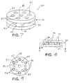
- a load bearing implant generally designated 62 in accordance with the present principles.
- the load bearing implant 62 is shown inverted 180° with respect to the load bearing implant device 50 of Fig. 3. This is for ease of depicting the optional fixation device portion 70 thereof.
- the load bearing implant device 62 includes a first plate, platform or the like 64 having a plurality of exposure pores, holes, bores or the like 65.
- the plurality of exposure holes 65 (here six of which are shown) are arranged in an annular manner about the plate 64.
- the number and/or arrangement of the exposure holes 65 is generally arbitrary, but may be arranged to control the exposure of the defect area and scaffold to the normal joint environment. The greater the hole area (hole size and hole number), the greater the exposure.
- the plate 64 also includes a centre hole or bore 76 that aids in insertion of the device 62 into the bone platform. 76 is the load-transferring mechanism, which in this case is a ring-shaped structure.
- the load bearing implant device 62 also includes a second plate, platform or the like 66 having a plurality of exposure pores, holes, bores or the like 67.
- the plurality of exposure holes 67 (here six of which are shown) are arranged in an annular manner about the plate 66.
- the number and/or arrangement of the holes 67 is generally arbitrary, but may be arranged to control the exposure of the defect area and scaffold to the normal joint environment. The greater the hole area (hole size and hole number), the greater the exposure.
- the plate 66 also includes a centre hole or bore 75 that aids in insertion of the device 62 into the bone platform.
- the centre hole 75 is intended to be just another bore.
- the fixation device 70 comprises a tubular body 71 that axially projects from the second plate 66.
- the tubular body 71 has an axial bore 72 that is aligned coaxially with the centre holes 75 and 77 of plates 66 and 64 respectively.
- a plurality of fins (anchors) 73 radially project from the tubular body 71.
- the fins 73 are fashioned as triangles.
- the fins may be embodied as ribs, barbs or the like and aid in the retention of the tubular body 71 in a bore in a defect area in the bone platform (see Fig. 32 and accompanying description).
- the fixation device 70 may takes other forms.
- the load bearing implant device 62 of Figs. 3-6 includes a load transfer structure 68.
- the load transfer structure 68 is embodied as a plurality (e.g. four as shown) of arc shaped or arcuate walls, portions, sections or the like 76.
- the arcuate walls 76 are situated about the centre holes 75 and 77 of the plates 66 and 64.
- the load transfer structure 68 is rigidly attached to both the first and second plates 64 and 66 to comprise a one-piece load bearing implant device.
- the load bearing implant device 62 also defines a cartilage scaffold/matrix retention area 74 between the platforms 64 and 66.
- the retention area 74 receives and retains a cartilage scaffold/matrix such as is known in the art.
- the load bearing implant device 80 is preferably made of the same material(s) as previously discussed.
- the load bearing implant device 80 has an upper or first plate or platform 82 and a lower or second plate or platform 84.
- the upper plate 82 includes a plurality of bores or holes 83 for defect area exposure in like manner to the load bearing implant device 62.
- the plurality of exposure bores 83 are arcuately spaced about a centre bore 86.
- the lower plate includes a plurality of bores or holes 85 for defect area exposure in like manner as the upper plate 82.
- the plurality of bores 85 are arcuately spaced about the centre bore 87.
- the number, size and/or arrangement of the bores 83 and 85 of the respective plates 82 and 84 may be modified as appropriate.
- the load bearing implant device 80 also defines a cartilage scaffold/matrix retention area 90 between the platforms 82 and 84.
- the retention area 90 receives and retains the cartilage scaffold/matrix.
- the load bearing implant device 80 of Figs. 7-9 also includes a load transfer structure 88.
- the load transfer structure 88 is embodied as a plurality (e.g. six as shown) of columns, cylinders or the like 92.
- the columns walls 92 are situated about the centre holes 86 and 87 of the plates 82 and 84.
- the load transfer structure 88 is rigidly attached to both the first and second plates 82 and 84 to comprise a one-piece load bearing implant device. Placement of the load transfer columns 92 may vary as appropriate.
- the load bearing implant device 80 is preferably made of the same material(s) as previously discussed.
- the load bearing implant device 96 includes an upper plate 98 and a lower plate 100.
- the upper plate 98 may or may not have exposure holes.
- the lower plate 100 includes a plurality of exposure bores 101 that are arcuately arranged in the plate about a centre bore 108. The number, size and/or arrangement of the bores 101 of the plate 100 may be modified as appropriate.
- the load bearing implant device 96 also defines a cartilage scaffold/matrix retention area 104 between the platforms 98 and 100.
- the retention area 104 receives and retains the cartilage scaffold/matrix.
- the load bearing implant device 80 of Figs. 10 and 11 includes a load transfer structure 102.
- the load transfer structure 102 is embodied as a plurality (e.g. three as shown) of rectangular walls, blocks or the like 106.
- the rectangular walls 92 extend radially from the centre hole 108 of the plate 100.
- the load transfer structure 102 is rigidly attached to both the first and second plates 98 and 100 to comprise a one-piece or unitary load bearing implant device.
- the upper plate 110 is preferably, but not necessarily, made of a polymeric material such as that described above.
- the upper plate 110 may be used in any of the implant embodiments shown herein. Particularly, the upper plate 110 may be used in place of the upper plate of any of the load bearing implant devices shown and/or described herein, or may be attached to the upper plate of any of the load bearing implant devices shown and/or described herein.
- the plate 110 is defined by a body 112 having a domed portion 114 surrounded by a rim 118.
- the dome portion 114 defines a convex articulating surface 115 and thus a concave underside surface 117.
- the configuration of the modified top 110 provides a condylar-shaped articulating surface.
- the plate 110 does not include exposure holes. In lieu of such exposure holes, the plate 110 may be porous or solid.
- one form of the present load bearing implant device is a two-piece design rather than a single piece design. It should be appreciated, however, that the load bearing implant device may be fashioned from more than two pieces if appropriate.
- an alternative embodiment of an upper platform structure is shown, generally designated 120, for a two-piece load bearing implant device.
- the upper platform structure 120 is again preferably made of a polymeric material as described above.
- the upper platform structure 120 includes a plate 122 having a plurality of exposure holes or bores 124 arcuately arranged about a centre bore 123.
- a load transfer structure 125 is integral with the plate 122 (i.e. a unitary structure).
- the load transfer structure 125 consists of a plurality (e.g., three as depicted) of rectangular blocks or walls 126 each having a mating structure 128.
- the load transfer structure 125 may consist of columns, rings, wedges or the like.
- the rectangular blocks extend radially outward from the centre hole 123 toward the periphery of the plate 122.
- Each mating or attachment structure 128 includes first and second prongs 130 and 131. Each prong extends axially upward then radially outward to define a hook shape. The hook shape provides mating of the prongs with a configured lower plate as shown in Figs 16-20.
- FIG. 16-20 there is depicted an exemplary lower platform structure generally designated 132 that may be used with the upper plate structure 120 of Figs. 14-15.
- the upper and lower platform structures 120 and 132 provide a two-piece snap or press fit implant design.
- the lower plate structure 132 is defined by a platform or plate 134 having a plurality of exposure bores 136.
- the plurality of exposure bores 136 are arcuately provided about a centre bore 137. Again, the size, number and/or arrangement of the exposure bores 136 are appropriate for the degree of exposure desired.
- the plate 134 further defines a rim 141 having a tapered, bevelled, or radiused edge 138. Extending radially outwardly from the centre bore 137 is a plurality of rectangular bores 139 each of which has a ledge, shelf, protrusion, tab or the like 140 that extends therein as part of a connection, attachment or mating structure. Each bore and ledge combination is configured to receive a prong 130/131 of each load transfer structure 126. This provides a snap or press fit attachment or connection of the upper platform structure 120 with the lower platform structure 132.
- the upper platform structure 120 is shown with two prongs 130/131 on each load transfer structure 126, while the receiving bores 139 of the lower plate structure 132 shows only one snap receiving structure 140 for clarity.
- the receiving bores 139 of the lower plate structure 132 shows only one snap receiving structure 140 for clarity.
- the two-piece structure of the load bearing implant device defined by the upper platform structure 120 and the lower platform structure 132 allows for easier manufacture of the implant device. Moreover, once the lower platform structure 132 is implanted into the patient, the resorbable cartilage scaffold/matrix is situated thereon. The upper platform structure 120 is then situated onto the lower platform structure 120. This gives the user the ability to select the type of resorbable scaffold/matrix material to be used with the load bearing implant device.
- a lower platform structure generally designated 150
- the lower platform structure 150 provides a twist and lock configuration for receiving, attaching and retaining an upper platform structure.
- the lower platform structure 150 is preferably made of a resorbable polymeric material such as that described above.
- the lower platform structure 150 is preferably a unitary piece.
- the lower platform structure 150 is defined by a disk-shaped body, plate or the like 152 defining a first surface 153 and an opposite second surface 155.
- the plate 152 further defines an annular rim or periphery 157 having an annular taper, bevel or angled portion 158 transitioning between the rim 157 and the angled portion 158.
- the plate 152 includes a plurality of exposure bores or holes 154 that are arranged about a centre bore or hole 156. As with previous plates, the size, number and arrangement of the exposure holes 154 and/or the centre hole 156, as well as whether to incorporate exposure holes or not, are subject to discretion depending on exposure factors. Additionally, the plate 152 has a plurality (e.g. three as shown) of configured bores 160 arranged about the centre hole 156 and adjacent the exposure holes 154. Each configured bore 160 is adapted to receive and retain a mating structure (e.g., mating structure 128 of Fig. 14) of the load transfer structure (e.g., load transfer structure 125 of Fig. 14) of the upper platform (e.g., upper platform structure 120 of Fig. 14).
- a mating structure e.g., mating structure 128 of Fig. 14
- the load transfer structure e.g., load transfer structure 125 of Fig. 14
- the upper platform e.g., upper platform structure 120 of
- Each configured bore 160 has a projection, ledge, shelf or the like 162 projecting into the interior of the bore.
- the ledge 162 defines a retention mechanism for a prong of the upper platform structure.
- Each prong would require a separate ledge.
- each configured bore 160 would require two ledge structures.
- FIG. 25 there is depicted another exemplary embodiment of an upper platform structure generally designated 170.
- the upper platform structure 170 provides another example of one portion of a two-piece load bearing implant structure.
- the upper platform structure 170 provides a structure that is retained onto a lower plate (see, e.g., plate 210 of Figs. 27-31) in a press or snap fit manner.
- the upper platform structure 170 is made of a polymeric material such as that described above and includes a plate 172 and a plurality of load transfer structures 176 that each axially extend from an upper surface 175 of the plate 172.
- the plate 172 also includes a centre bore 174.
- Each load transfer structure 176 is fashioned as a wedge having a mating structure 178 thereon.
- Each mating structure 178 is configured to be press fit received into a complementary lower platform structure or plate.
- each mating structure 178 is here embodied as a truncated cone (cone section) 180 having two, diametrically opposed flanges 181. While only two flanges 181 are shown, the cone section 180 may support more or less flanges 181 as deemed appropriate.
- FIG. 26 there is shown another exemplary embodiment of an upper platform structure generally designated 190.
- the upper platform structure 190 provides another example of one portion of a two-piece load bearing implant structure.
- the upper platform structure 190 provides a structure that is retained onto a lower plate (see, e.g., plate 210 of Figs. 27-31) in a press or snap fit manner.
- the upper platform structure 190 is made of a polymeric material such as that described above and includes a plate 192 having a plurality of exposure bores 194 arranged about a centre hole 196.
- the plate 192 supports a plurality of load transfer structures 198 that each axially extend from an upper surface 195 of the plate 192.
- Each load transfer structure 198 is configured as a column, tube or the like having a first conical section or annular taper 200 and a second conical section, cone or tapered head 202.
- the cone 202 defines a skirt 203 that provides a manner of preventing the pulling out or reversal of the load transfer structure 198 when inserted into the corresponding lower platform structure. Cone 202 is intended to provide a mechanism for fixation into the subchondral bone.
- the lower platform structure 210 is defined by a body 212 in the shape of a plate, platform or the like that is fashioned from a suitable resorbable polymeric material such as that described above.
- the plate 212 defines an annular rim or periphery 218 between a first surface 213 and a second surface 215. Additionally, the plate 212 has an annular taper, bevel or angled surface 219 providing a transition between the rim 219 and the second surface 215.
- the plate 212 further includes a plurality of exposure holes 216 that are arranged about a centre bore 214.
- the size, number and/or arrangement of the exposure bores 216 are modifiable as necessary.
- Situated between each exposure bore 216 is a receiving, reception or mating bore 220 for a plurality of receiving bores 220.
- each receiving bore 220 is conical in shape and includes notches 221.
- the notches 221 allow for the reception of the flanges 181 of the load transfer structures 180 of the upper platform structure 170 of Fig. 25, and the reception of the skirt 203 of the upper platform structure 190 of Fig. 26.
- FIG. 32 there is depicted an exemplary illustration depicting a load bearing implant device 240 fashioned in accordance with the principles of the subject invention implanted into a defect area 230 of a bone platform 228.
- a bore 236 has been formed in the subchondral bone 232 below the defect area in order to accommodate the fixation device 248 of the load bearing implant device 240.
- the first or lower plate 244 of the load bearing implant device 240 is situated proximate and/or adjacent the subchondral bone 232 where the cartilage 234 meets the subchondral bone 232.
- the second or upper plate 242 of the load bearing implant device 240 is situated at the surface of the cartilage 234.
- a scaffold or matrix 252 is situated in between the two plates 242, 244 within the scaffold/matrix reception area of the load bearing implant device.
- load or pressure exerted onto the load bearing implant device structure (e.g., upper plate) at the articulating surface transfers the physiologic load to the load transfer structure.
- the load transfer structure then transfers the load to the device structure (e.g., lower plate) adjacent the defect area of the subchondral bone.
- This exerted pressure on the subchondral bone reduces the resorption of subchondral bone and/or the stimulation of subchondral bone synthesis.
- the load bearing implant device itself is resorbable, being preferably made of a resorbable polymeric material or materials.
- the subject invention also aids in the regeneration of cartilage tissue in load bearing regions with the ability to receive and retain a resorbable, cartilage regeneration scaffold or matrix (mesh, foam or the like).
Landscapes
- Health & Medical Sciences (AREA)
- Orthopedic Medicine & Surgery (AREA)
- Cardiology (AREA)
- Oral & Maxillofacial Surgery (AREA)
- Transplantation (AREA)
- Engineering & Computer Science (AREA)
- Biomedical Technology (AREA)
- Heart & Thoracic Surgery (AREA)
- Vascular Medicine (AREA)
- Life Sciences & Earth Sciences (AREA)
- Animal Behavior & Ethology (AREA)
- General Health & Medical Sciences (AREA)
- Public Health (AREA)
- Veterinary Medicine (AREA)
- Rheumatology (AREA)
- Prostheses (AREA)
- Materials For Medical Uses (AREA)
Abstract
Description
- The present invention relates to regeneration of cartilaginous tissue in load bearing regions and/or the tendency toward the resorption of subchondral bone and, more particularly, to an implant device for reducing the resorption of subchondral bone and thereby enhancing the regeneration of cartilaginous tissue in load bearing regions.
- Current techniques for repair and/or regeneration of articular lesions (autogenous chondrocyte transplantation and mosaicplasty) are generally considered to be unsatisfactory due to the fact that they require the harvesting of healthy tissue. As such, research has focussed on the development of engineered devices that have the ability to stimulate conduction of hyaline-like tissue into the treated regions without using autogenous tissue sources. Such devices would be considered optimized scaffolds.
- In vivo studies of articular cartilage regeneration typically utilize one of two animal models: the osteochondral defect and the full-thickness chondral defect. The osteochondral defect model is ideal for the generation of cartilage neotissue because access to the traumatized bone bed allows for recruitment of precursor cells, thereby enhancing the intrinsic wound healing response. In fact, osteochondral defects in the non-load-bearing areas heal spontaneously, albeit with fibrous tissue. The load-bearing region, however, is known to not heal spontaneously, and is characteristically accompanied by resorption of osseous walls and the formation of cavitary lesions.
- In cases where load-bearing surfaces have been investigated with good outcomes, care has been taken not to compromise the subchondral plate (e.g. full-thickness chondral defect model). However, because the chondral defect model does not generate a hematopoietic wound healing response, spontaneous regeneration does not occur and thus cellular therapies are usually used in such circumstances. One notable exception is mosaicplasty. Mosaicplasty in femoral condyle (osteochondral) defects has been shown to maintain subchondral bone structure, further indicating that application of physiologic force plays a role in maintaining subchondral bone integrity.
- Particularly, mosaicplasty utilizes cartilaginous plugs, but due to the need to harvest tissue from other sites, this technique is sometimes viewed as being suboptimal. Therefore, research has focussed on the use of implant devices. US-A-2001/0039455 discloses prosthetic bio-compatible polyurethane plugs that mimic the materials properties of the adjacent bone or cartilage tissue layer. These implants are intended to fill a cartilaginous defect with a non-resorbable cartilage-like material. However, application of load to subchondral bone is not described.
- The use of load during cartilage regeneration has been described in several publications. US-6530956 discloses a resorbable cage-like scaffold that consists of high porosity material seeded with transplanted chondrocytes. Loading is discussed with respect to the cage-like scaffold for withstanding and resisting compressive forces so that cell growing compartments of the cage-like scaffold are protected during tissue regeneration.
- US-6511511 discloses a fibre-reinforced, porous, biodegradable implant in which the fibres act like struts to provide strength and stiffness to the scaffold and provide support for physiological loads. One particular embodiment is for osteochondral defects. Loading, however, is discussed only with respect to the device resisting high compressive stresses in the defect region thereby protecting the implant during tissue regeneration. In a similar manner, US-A-2002/0119177 discloses a method for reinforcing the mechanical and handling properties of a resorbable foam matrix using a mesh-like fabric. The primary purpose of the reinforcing mesh is to maintain the integrity of the foam component for surgical handling.
- US-A-2003/0108587 discloses an implantable device that can induce compression, tension, shear and other biomechanical forces to cells in order to induce cell proliferation and thus wound healing. The device is essentially a bioreactor that exerts micromechanical stimulation to cells through materials properties or application of external forces. This is taught, however, with respect to the regeneration of cartilage and not with respect to the healing of the subchondral bone as in the present invention.
- Thus the need exists for a device for regeneration of articular cartilage that simultaneously applies load to subchondral bone.
- In one form, the present invention is an implant device for applying a load to osteochondral defects. In another form, the present invention provides cartilage regeneration of osteochondral defects in load bearing regions. The implant may be fashioned as one integral device or may be fashioned as two or more portions that are attached to one another.
- The device of the invention can provide cartilage regeneration in load-bearing regions. It can apply a load from an articulating surface of a bone platform to an area of subchondral bone. It can reduce subchondral bone resorption.
- The implant includes an upper platform structure and a lower platform structure with a load transfer structure situated there between. A fixation structure may be included that aids in anchoring the implant to the defect area. The implant is comprised of a resorbable polymeric material or materials such as polyesters (polylactide, polyglycolide, polycaprolactone, polydioxanone, or combination thereof), co-polymers of resorbable polymers, or blends thereof.
- The lower platform structure is preferably rigid (and alternatively the upper platform structure as well) and may be porous, or include pores or holes that allow for access to biologic elements (e.g. blood and bone marrow) from the subchondral bone. The implant also allows the receipt and retention of a resorbable scaffold or matrix material for cartilage regeneration in the defect area.
- Particularly, in one form there is provided an implant device for an osteochondral defect. The implant device includes a first plate made of a resorbable biocompatible material, a second plate made of the resorbable biocompatible material, and a load transfer structure made of the resorbable biocompatible material and situated between the first plate and the second plate.
- In another form, there is provided an implant device for an osteochondral defect. The implant device includes an upper plate made of a resorbable biocompatible polymer, a lower plate made of the resorbable biocompatible polymer and having a plurality of exposure bores, and a load transfer structure situated between the upper plate and the lower plate.
- In yet another form, there is provided an implant for load bearing bone articulation surfaces. The implant includes an upper plate made of a bio-resorbable polymer and having an upper centre bore, a lower plate made of the bio-resorbable polymer and having a lower centre bore surrounded by a plurality of exposure bores, and a plurality of load transfer supports situated between a lower surface of the upper plate and an upper surface of the lower plate, the load transfer supports surrounding the upper and lower centre bores.
- Embodiments of the invention will now be described by way of example with referee to the accompanying drawings, in which:
- Fig. 1 is a diagrammatic view showing a tibial platform, representing an exemplary bone platform, being below the condyles of the femur; representing exemplary condyles; may also want to show patella.
- Fig. 2 is a block diagram illustrating an exemplary general form of a load bearing cartilage regeneration device in accordance with the principles of the subject invention;
- Fig. 3 is an enlarged perspective view of an exemplary embodiment of a load bearing cartilage regeneration device in accordance with the principles of the subject invention;
- Fig. 4 is a side view of the load bearing cartilage regeneration device of Fig. 3;
- Fig. 5 is a sectional view of the load bearing cartilage regeneration device of Fig. 4 taken along line 5-5 thereof, particularly showing the lower platform thereof;
- Fig. 6 is a sectional view of the load bearing cartilage regeneration device of Fig. 4 taken along line 6-6 thereof, particularly showing the upper platform thereof; including the load transferring structure.
- Fig. 7 is an enlarged perspective view of another exemplary embodiment of a load bearing cartilage regeneration device in accordance with the principles of the subject invention;
- Fig. 8 is a side view of the load bearing cartilage regeneration device of Fig. 7;
- Fig. 9 is a sectional view of the load bearing cartilage regeneration device of Fig. 8 taken along line 9-9 thereof, particularly showing the lower platform thereof; including the load transferring structure.
- Fig. 10 is a side view of another exemplary embodiment of a load bearing cartilage regeneration device in accordance with the principles of the subject invention;
- Fig. 11 is a sectional view of the load bearing cartilage regeneration device of Fig. 10 taken along line 11-11 thereof, particularly showing the lower platform thereof; including the load transferring structure.
- Fig. 12 is an enlarged bottom perspective view of an alternative upper platform utilizable with the various exemplary embodiments;
- Fig. 13 is a side view of the upper platform of Fig. 12;
- Fig. 14 is an enlarged top perspective view of an alternative embodiment of a platform having integral load transfer structures for a two-piece load bearing cartilage regeneration device, the load transfer structures designed to engage mating structures on a mating platform of the two-piece load bearing cartilage regeneration device such as that depicted in Fig. 16;
- Fig. 15 is a top view of the platform of Fig. 14;
- Fig. 16 is an enlarged top perspective view of an exemplary mating platform for the platform structure of Fig. 14;
- Fig. 17 is a side view of the exemplary mating platform of Fig. 16;
- Fig. 18 is a sectional view of the exemplary mating platform of Fig. 17 taken along line 18-18 thereof;
- Fig. 19 is a top plan view of the exemplary mating platform of Fig. 16;
- Fig. 20 is a sectional view of the exemplary mating platform of Fig. 19 taken along line 20-20 thereof;
- Fig. 21 is an enlarged top perspective view of another exemplary mating platform for the platform structure of Fig. 14;
- Fig. 22 is a top plan view of the exemplary mating platform of Fig. 21;
- Fig. 23 is a side view of the exemplary mating platform of Fig. 21;
- Fig. 24 is a sectional view of the exemplary mating platform of Fig. 23 taken along line 24-24 thereof;
- Fig. 25 is an enlarged top perspective view of another alternative embodiment of a platform having integral load transfer structures for a two-piece load bearing cartilage regeneration device, the load transfer structures designed to engage mating structures on a mating platform of the two-piece load bearing cartilage regeneration device;
- Fig. 26 is an enlarged top perspective view of yet another alternative embodiment of a platform having integral load transfer structures for a two-piece load bearing cartilage regeneration device, the load transfer structures designed to engage mating structures on a mating platform of the two-piece load bearing cartilage regeneration device;
- Fig. 27 is an enlarged top perspective view of an exemplary mating platform for the platform structures of Figs. 25 and/or 26;
- Fig. 28 is a side view of the exemplary mating platform of Fig. 27;
- Fig. 29 is a sectional view of the exemplary mating platform of Fig. 28 taken along line 29-29 thereof;
- Fig. 30 is a top plan view of the exemplary mating platform of Fig. 27;
- Fig. 31 is a sectional view of the exemplary mating platform of Fig. 30 taken along line 31-31 thereof; and
- Fig. 32 is an enlarged side sectional view of a bone and cartilage platform depicting an exemplary load bearing cartilage regeneration device in accordance with the principles of the present invention implanted therein.
-
- Referring to the drawings, Fig. 1 shows a bone platform generally designated 40 being situated below
condyles 42. Thebone platform 40 of Fig. 1 is depicted as atibial platform 40 of atibia 41 while thecondyles 42 are of a femur/knee. It should be appreciated that thetibial platform 40 andcondyles 42 are representative of any similar bone platform. Thetibial platform 40 supports ameniscus 44 that is oversubchondral bone 45. Thetibial platform 40 is assumed to have an osteochondral defect. The subject invention provides an implantable device for the osteochondral defect. Thecondyles 42 typically exert a load represented by arrows L onto thetibial platform 40. Particularly, thecondyles 42 of thefemur 43 exert physiological loading on thetibial platform 40 during normal joint use. The implant is actually intended for a medial femoral condylar (MFC) defect, and our initial data is in the MFC. Perhaps we should describe Fig 1 relating to a MFC defect, and mention the other load-bearing surfaces such as the tibia and patella? - Referring now to Fig. 2, there is depicted a block diagram of a load bearing subchondral bone resorption reduction and/or cartilage regeneration implant device generally designated 50 (and, hereinafter, "load bearing implant device", "implant" or the like) in accordance with the principles of the subject invention. The load
bearing implant device 50 is representative of a general structure of the various embodiments of the present load bearing implant device shown and/or described herein. - The load
bearing implant device 50 includes a first or upper platform, plate or the like 52 and a second or lower platform, plate or the like 54. It should be appreciated that the designations "first", "second", "upper" and "lower" are arbitrary. Aload transfer structure 56 is interposed between the upper andlower platforms 52, 54. Theload transfer structure 56 may take various forms but supports and transfers loading (e.g. physiological loading) exerted on the upper platform 52 to thelower platform 54. Thelower platform 54 transfers the loading exerted thereon by theload transfer structure 56 to the substance of the area in which it is implanted (e.g. subchondral bone). - The load
bearing implant device 50 is also shown with afixation device 58. Thefixation device 58 is depicted in dashed lines to indicate the optional nature thereof. Thus, thefixation device 58 is not a necessary portion of theimplant 50. It is preferable, however, that the implant has some sort of fixation device. Thefixation device 58 extends generally axially from thelower platform 54 and is utilized to aid in mounting the loadbearing implant device 50 into the bone platform. Thefixation device 58 may take various forms which are suitable for mounting the implant into bone (e.g.,tibia 41 or condyle 43). - The upper and
lower platforms 52, 54 are axially spaced from one another by theload transfer structure 56. An area 60 between the upper platform 52 and thelower platform 54 may be utilized to retain a scaffold, matrix or the like of a resorbable material that supports cartilage regeneration (e.g. a bio or artificial material). As such, the area 60 may be termed a scaffold or matrix retention area. The loadbearing implant device 50 is designed such that the scaffold or matrix may be inserted before or after thedevice 50 has been implanted into the bone platform. Whether or not the scaffold or matrix is inserted before or after implantation may depend on the particular form of the loadbearing implant device 50. Particularly, a one-piece implant design may have the scaffold before implantation thereof, while a two-piece implant may receive the scaffold after implantation thereof. - The load
bearing implant device 50 is comprised of a bio-resorbable (resorbable) material. The resorbable material is preferably a poly(ester)s such as poly(lactide), poly(glycolide), poly(caprolactone), poly(dioxanone) or any combination, co-polymer or blend thereof. Other types of resorbable material(s) may also be used. - The
lower platform 54 is preferably, but not necessarily, rigid yet porous. Such porosity may be effected by a porous material or the incorporation of bores, holes, pores or the like. As such thelower platform 54 allows the body access to biologic elements (bone and marrow) from the subchondral bone of the bone platform when theimplant device 50 is implanted. The upper plate 52 is preferably likewise rigid, but may or may not be porous. - The
load transfer structure 56 may be rigidly attached to both the upper plate 52 and thebottom plate 54 such that the loadbearing implant device 50 is generally of a unitary or single piece structure. Particularly, theload transfer structure 56 adjoins thelower surface 53 of the upper plate 52 and theupper surface 55 of thelower plate 54. Alternatively, theload transfer structure 56 may be rigidly attached to the upper plate 52 and include a mechanism, structure or configuration that attaches or connects to thelower plate 54 via a mating mechanism, structure or configuration. - It should be appreciated that the attributes of the general load bearing
implant device 50 as described above is applicable to the various particular embodiments of the load bearing implant device described hereinafter. Therefore, unless noted otherwise, the load bearing implant devices described below, have and/or exhibit the same attributes as those described for theimplant device 50. - Referring now to Figs. 3-6, there is depicted an exemplary embodiment of a load bearing implant generally designated 62 in accordance with the present principles. Initially, it should be appreciated that the
load bearing implant 62 is shown inverted 180° with respect to the loadbearing implant device 50 of Fig. 3. This is for ease of depicting the optionalfixation device portion 70 thereof. - The load
bearing implant device 62 includes a first plate, platform or the like 64 having a plurality of exposure pores, holes, bores or the like 65. The plurality of exposure holes 65 (here six of which are shown) are arranged in an annular manner about theplate 64. The number and/or arrangement of the exposure holes 65 is generally arbitrary, but may be arranged to control the exposure of the defect area and scaffold to the normal joint environment. The greater the hole area (hole size and hole number), the greater the exposure. Theplate 64 also includes a centre hole or bore 76 that aids in insertion of thedevice 62 into the bone platform. 76 is the load-transferring mechanism, which in this case is a ring-shaped structure. - The load
bearing implant device 62 also includes a second plate, platform or the like 66 having a plurality of exposure pores, holes, bores or the like 67. Again, the plurality of exposure holes 67 (here six of which are shown) are arranged in an annular manner about theplate 66. The number and/or arrangement of theholes 67 is generally arbitrary, but may be arranged to control the exposure of the defect area and scaffold to the normal joint environment. The greater the hole area (hole size and hole number), the greater the exposure. Theplate 66 also includes a centre hole or bore 75 that aids in insertion of thedevice 62 into the bone platform. Thecentre hole 75 is intended to be just another bore. - The
fixation device 70 comprises atubular body 71 that axially projects from thesecond plate 66. Thetubular body 71 has an axial bore 72 that is aligned coaxially with the centre holes 75 and 77 ofplates tubular body 71. Thefins 73 are fashioned as triangles. The fins may be embodied as ribs, barbs or the like and aid in the retention of thetubular body 71 in a bore in a defect area in the bone platform (see Fig. 32 and accompanying description). Of course, thefixation device 70, may takes other forms. - The load
bearing implant device 62 of Figs. 3-6 includes aload transfer structure 68. Theload transfer structure 68 is embodied as a plurality (e.g. four as shown) of arc shaped or arcuate walls, portions, sections or the like 76. Thearcuate walls 76 are situated about the centre holes 75 and 77 of theplates load transfer structure 68 is rigidly attached to both the first andsecond plates - The load
bearing implant device 62 also defines a cartilage scaffold/matrix retention area 74 between theplatforms retention area 74 receives and retains a cartilage scaffold/matrix such as is known in the art. - Referring now to Figs. 7-9, there is depicted an alternative embodiment of the present load bearing implant device generally designated 80. The load
bearing implant device 80 is preferably made of the same material(s) as previously discussed. The loadbearing implant device 80 has an upper or first plate orplatform 82 and a lower or second plate orplatform 84. Theupper plate 82 includes a plurality of bores or holes 83 for defect area exposure in like manner to the loadbearing implant device 62. The plurality of exposure bores 83 are arcuately spaced about a centre bore 86. The lower plate includes a plurality of bores or holes 85 for defect area exposure in like manner as theupper plate 82. The plurality ofbores 85 are arcuately spaced about the centre bore 87. The number, size and/or arrangement of thebores respective plates - The load
bearing implant device 80 also defines a cartilage scaffold/matrix retention area 90 between theplatforms retention area 90 receives and retains the cartilage scaffold/matrix. - The load
bearing implant device 80 of Figs. 7-9 also includes aload transfer structure 88. Theload transfer structure 88 is embodied as a plurality (e.g. six as shown) of columns, cylinders or the like 92. Thecolumns walls 92 are situated about the centre holes 86 and 87 of theplates load transfer structure 88 is rigidly attached to both the first andsecond plates load transfer columns 92 may vary as appropriate. - Referring now to Figs. 10 and 11, another alternative embodiment of a load bearing implant device is shown, generally designated 96. The load
bearing implant device 80 is preferably made of the same material(s) as previously discussed. The loadbearing implant device 96 includes anupper plate 98 and alower plate 100. Theupper plate 98 may or may not have exposure holes.. Thelower plate 100 includes a plurality of exposure bores 101 that are arcuately arranged in the plate about acentre bore 108. The number, size and/or arrangement of thebores 101 of theplate 100 may be modified as appropriate. - The load
bearing implant device 96 also defines a cartilage scaffold/matrix retention area 104 between theplatforms retention area 104 receives and retains the cartilage scaffold/matrix. - The load
bearing implant device 80 of Figs. 10 and 11 includes aload transfer structure 102. Theload transfer structure 102 is embodied as a plurality (e.g. three as shown) of rectangular walls, blocks or the like 106. Therectangular walls 92 extend radially from thecentre hole 108 of theplate 100. In this embodiment, theload transfer structure 102 is rigidly attached to both the first andsecond plates - Referring now to Figs. 12 and 13, an alternative embodiment or modification of an upper plate or platform is shown, generally designated 110. The
upper plate 110 is preferably, but not necessarily, made of a polymeric material such as that described above. Theupper plate 110 may be used in any of the implant embodiments shown herein. Particularly, theupper plate 110 may be used in place of the upper plate of any of the load bearing implant devices shown and/or described herein, or may be attached to the upper plate of any of the load bearing implant devices shown and/or described herein. - The
plate 110 is defined by abody 112 having adomed portion 114 surrounded by arim 118. Thedome portion 114 defines a convex articulatingsurface 115 and thus aconcave underside surface 117. The configuration of the modifiedtop 110 provides a condylar-shaped articulating surface. Preferably, but not necessarily, theplate 110 does not include exposure holes. In lieu of such exposure holes, theplate 110 may be porous or solid. - As indicated above, one form of the present load bearing implant device is a two-piece design rather than a single piece design. It should be appreciated, however, that the load bearing implant device may be fashioned from more than two pieces if appropriate.
- Referring now to Figs. 14 and 15, an alternative embodiment of an upper platform structure is shown, generally designated 120, for a two-piece load bearing implant device. The
upper platform structure 120 is again preferably made of a polymeric material as described above. - The
upper platform structure 120 includes aplate 122 having a plurality of exposure holes or bores 124 arcuately arranged about acentre bore 123. Aload transfer structure 125 is integral with the plate 122 (i.e. a unitary structure). Theload transfer structure 125 consists of a plurality (e.g., three as depicted) of rectangular blocks orwalls 126 each having amating structure 128. Of course, theload transfer structure 125 may consist of columns, rings, wedges or the like. The rectangular blocks extend radially outward from thecentre hole 123 toward the periphery of theplate 122. Each mating orattachment structure 128 includes first andsecond prongs - Referring now to Figs. 16-20, there is depicted an exemplary lower platform structure generally designated 132 that may be used with the
upper plate structure 120 of Figs. 14-15. The upper andlower platform structures lower plate structure 132 is defined by a platform orplate 134 having a plurality of exposure bores 136. The plurality of exposure bores 136 are arcuately provided about acentre bore 137. Again, the size, number and/or arrangement of the exposure bores 136 are appropriate for the degree of exposure desired. - The
plate 134 further defines a rim 141 having a tapered, bevelled, or radiusededge 138. Extending radially outwardly from the centre bore 137 is a plurality ofrectangular bores 139 each of which has a ledge, shelf, protrusion, tab or the like 140 that extends therein as part of a connection, attachment or mating structure. Each bore and ledge combination is configured to receive aprong 130/131 of eachload transfer structure 126. This provides a snap or press fit attachment or connection of theupper platform structure 120 with thelower platform structure 132. - It should be appreciated that the
upper platform structure 120 is shown with twoprongs 130/131 on eachload transfer structure 126, while the receiving bores 139 of thelower plate structure 132 shows only onesnap receiving structure 140 for clarity. In order to actually receive the upper platform structure onto the lower platform structure, there would either be only one prong on the load transfer structure of the upper platform structure, or there would be two receiving structures in the receiving bore. - The two-piece structure of the load bearing implant device defined by the
upper platform structure 120 and thelower platform structure 132 allows for easier manufacture of the implant device. Moreover, once thelower platform structure 132 is implanted into the patient, the resorbable cartilage scaffold/matrix is situated thereon. Theupper platform structure 120 is then situated onto thelower platform structure 120. This gives the user the ability to select the type of resorbable scaffold/matrix material to be used with the load bearing implant device. - With the two-piece axial snap or press fit design of Figs. 14-20, almost all of the force that will be exerted onto the implant device will be axial loading. As such, there the
upper platform structure 120 will resist separation from the lower platform structure. - Referring now to Figs. 21-24, there is depicted an alternative embodiment of a lower platform structure, generally designated 150, that may be used with the upper platform structure of Figs. 14-15. The
lower platform structure 150 provides a twist and lock configuration for receiving, attaching and retaining an upper platform structure. Thelower platform structure 150 is preferably made of a resorbable polymeric material such as that described above. Moreover, thelower platform structure 150 is preferably a unitary piece. - The
lower platform structure 150 is defined by a disk-shaped body, plate or the like 152 defining afirst surface 153 and an oppositesecond surface 155. Theplate 152 further defines an annular rim orperiphery 157 having an annular taper, bevel orangled portion 158 transitioning between therim 157 and theangled portion 158. - The
plate 152 includes a plurality of exposure bores orholes 154 that are arranged about a centre bore orhole 156. As with previous plates, the size, number and arrangement of the exposure holes 154 and/or thecentre hole 156, as well as whether to incorporate exposure holes or not, are subject to discretion depending on exposure factors. Additionally, theplate 152 has a plurality (e.g. three as shown) of configuredbores 160 arranged about thecentre hole 156 and adjacent the exposure holes 154. Each configured bore 160 is adapted to receive and retain a mating structure (e.g.,mating structure 128 of Fig. 14) of the load transfer structure (e.g.,load transfer structure 125 of Fig. 14) of the upper platform (e.g.,upper platform structure 120 of Fig. 14). - Each configured bore 160 has a projection, ledge, shelf or the like 162 projecting into the interior of the bore. The
ledge 162 defines a retention mechanism for a prong of the upper platform structure. Each prong would require a separate ledge. Thus, to receive the two-pronged load transfer structure of the upper platform structure of Figs. 14-15, each configured bore 160 would require two ledge structures. Once a prong is inserted into the configured bore, a twist thereof sets the ledge into under each prong. This motion, twist locks the upper plate platform into the lower plate platform. - In Fig. 25, there is depicted another exemplary embodiment of an upper platform structure generally designated 170. The
upper platform structure 170 provides another example of one portion of a two-piece load bearing implant structure. Particularly, theupper platform structure 170 provides a structure that is retained onto a lower plate (see, e.g.,plate 210 of Figs. 27-31) in a press or snap fit manner. - The
upper platform structure 170 is made of a polymeric material such as that described above and includes aplate 172 and a plurality ofload transfer structures 176 that each axially extend from anupper surface 175 of theplate 172. Theplate 172 also includes a centre bore 174. - Each
load transfer structure 176 is fashioned as a wedge having amating structure 178 thereon. Eachmating structure 178 is configured to be press fit received into a complementary lower platform structure or plate. Particularly, eachmating structure 178 is here embodied as a truncated cone (cone section) 180 having two, diametricallyopposed flanges 181. While only twoflanges 181 are shown, thecone section 180 may support more orless flanges 181 as deemed appropriate. - Referring now to Fig. 26, there is shown another exemplary embodiment of an upper platform structure generally designated 190. The
upper platform structure 190 provides another example of one portion of a two-piece load bearing implant structure. Particularly, theupper platform structure 190 provides a structure that is retained onto a lower plate (see, e.g.,plate 210 of Figs. 27-31) in a press or snap fit manner. - The
upper platform structure 190 is made of a polymeric material such as that described above and includes aplate 192 having a plurality of exposure bores 194 arranged about acentre hole 196. Theplate 192 supports a plurality ofload transfer structures 198 that each axially extend from anupper surface 195 of theplate 192. Eachload transfer structure 198 is configured as a column, tube or the like having a first conical section orannular taper 200 and a second conical section, cone or taperedhead 202. Thecone 202 defines askirt 203 that provides a manner of preventing the pulling out or reversal of theload transfer structure 198 when inserted into the corresponding lower platform structure.Cone 202 is intended to provide a mechanism for fixation into the subchondral bone. - Referring now to Figs. 27-31, there is depicted an exemplary lower platform structure, generally designated 210, that can accommodate either one of the two exemplary
upper platform structures 170 of Fig. 25 and 190 of Fig. 26. Thelower platform structure 210 is defined by abody 212 in the shape of a plate, platform or the like that is fashioned from a suitable resorbable polymeric material such as that described above. Theplate 212 defines an annular rim orperiphery 218 between afirst surface 213 and asecond surface 215. Additionally, theplate 212 has an annular taper, bevel orangled surface 219 providing a transition between therim 219 and thesecond surface 215. - The
plate 212 further includes a plurality of exposure holes 216 that are arranged about acentre bore 214. The size, number and/or arrangement of the exposure bores 216 are modifiable as necessary. Situated between each exposure bore 216 is a receiving, reception or mating bore 220 for a plurality of receiving bores 220. As best seen in Fig. 31, each receivingbore 220 is conical in shape and includesnotches 221. Thenotches 221 allow for the reception of theflanges 181 of theload transfer structures 180 of theupper platform structure 170 of Fig. 25, and the reception of theskirt 203 of theupper platform structure 190 of Fig. 26. - Referring lastly to Fig. 32, there is depicted an exemplary illustration depicting a load bearing implant device 240 fashioned in accordance with the principles of the subject invention implanted into a
defect area 230 of abone platform 228. Abore 236 has been formed in thesubchondral bone 232 below the defect area in order to accommodate thefixation device 248 of the load bearing implant device 240. - The first or
lower plate 244 of the load bearing implant device 240 is situated proximate and/or adjacent thesubchondral bone 232 where thecartilage 234 meets thesubchondral bone 232. The second orupper plate 242 of the load bearing implant device 240 is situated at the surface of thecartilage 234. A scaffold ormatrix 252 is situated in between the twoplates - In each embodiment, load or pressure exerted onto the load bearing implant device structure (e.g., upper plate) at the articulating surface transfers the physiologic load to the load transfer structure. The load transfer structure then transfers the load to the device structure (e.g., lower plate) adjacent the defect area of the subchondral bone. This exerted pressure on the subchondral bone reduces the resorption of subchondral bone and/or the stimulation of subchondral bone synthesis. The load bearing implant device itself is resorbable, being preferably made of a resorbable polymeric material or materials. The subject invention also aids in the regeneration of cartilage tissue in load bearing regions with the ability to receive and retain a resorbable, cartilage regeneration scaffold or matrix (mesh, foam or the like).
Claims (22)
- An implant device for an osteochondral defect comprising:a first plate made of a resorbable biocompatible material;a second plate made of said resorbable biocompatible material; anda load transfer structure made of said resorbable biocompatible material and situated between said first plate and said second plate.
- The implant device of claim 1, wherein said resorbable biocompatible material is a polymer.
- The implant device of claim 2, wherein said polymer comprises polyester.
- The implant device of claim 1, wherein said second plate is porous.
- The implant device of claim 1, wherein said first plate, said second plate and said load transfer structure comprise a unitary structure.
- The implant device of claim 1, wherein said load transfer structure is integral with said first plate, and receivable by said second plate.
- The implant device of claim 1, further comprising a fixation device extending from said second plate.
- The implant device of claim 1, in which the first plate is an upper plate which comprises a biocompatible polymer.
- The implant device of claim 1, in which the second plate is a lower plate and has a plurality of exposure bores.
- The implant device of claim 1, which includes a fixation member axially extending from a bottom surface of said second plate.
- The implant device of claim 10, wherein said fixation member comprises a stem having a plurality of radially extending barbs.
- The implant device of claim 1, wherein said implant device is adapted to receive a resorbable cartilage scaffold between the first and second plates.
- The implant device of claim 1, wherein said first plate is porous.
- The implant device of claim 1, wherein said load transfer structure includes an attachment structure configured to be press fit into receiving bores in the second plate.
- The implant device of claim 14, wherein said load transfer structure comprises a plurality of individual supports, and said attachment structure comprises an attachment component associated with each individual support.
- An implant for load bearing bone articulation surfaces comprising:an upper plate made of a bio-resorbable polymer and having an upper centre bore;a lower plate made of the bio-resorbable polymer and having a lower centre bore surrounded by a plurality of exposure bores; anda plurality of load transfer supports situated between a lower surface of said upper plate and an upper surface of said lower plate, said load transfer supports surrounding said upper and lower centre bores.
- The implant of claim 16, wherein a scaffold retention area is defined about said load transfer supports.
- The implant of claim 18, wherein said fixation member comprises:a tube having a centre bore that is coaxial with said upper and lower centre bores; anda plurality of retention flanges extending radially from an outside surface of said tube.
- The implant of claim 16, wherein said upper plate, said lower plate and said load transfer structure comprise a unitary structure.
- The implant of claim 16, wherein said load transfer structure is integral with said upper plate and receivable by said lower plate.
- The implant of claim 20, wherein said load transfer structure includes an attachment structure configured to be press fit into receiving bores in said lower plate.
- The implant of claim 21, wherein said load transfer structure comprises a plurality of individual supports, and said attachment structure comprises an attachment component associated with each individual support.
Applications Claiming Priority (2)
| Application Number | Priority Date | Filing Date | Title |
|---|---|---|---|
| US730423 | 1996-10-15 | ||
| US10/730,423 US7666230B2 (en) | 2003-12-08 | 2003-12-08 | Implant device for cartilage regeneration in load bearing articulation regions |
Publications (2)
| Publication Number | Publication Date |
|---|---|
| EP1541095A2 true EP1541095A2 (en) | 2005-06-15 |
| EP1541095A3 EP1541095A3 (en) | 2006-01-04 |
Family
ID=34523011
Family Applications (1)
| Application Number | Title | Priority Date | Filing Date |
|---|---|---|---|
| EP04257488A Withdrawn EP1541095A3 (en) | 2003-12-08 | 2004-12-02 | Implant device for cartilage regeneration in load bearing articulation regions |
Country Status (4)
| Country | Link |
|---|---|
| US (1) | US7666230B2 (en) |
| EP (1) | EP1541095A3 (en) |
| JP (1) | JP2005169117A (en) |
| AU (1) | AU2004235623A1 (en) |
Cited By (8)
| Publication number | Priority date | Publication date | Assignee | Title |
|---|---|---|---|---|
| WO2007007106A1 (en) * | 2005-07-13 | 2007-01-18 | Smith & Nephew, Plc | Implants for tissue repair |
| WO2013053966A1 (en) * | 2011-10-10 | 2013-04-18 | Universidad Politécnica De Valencia | Device for attaching a macroporous material for regenerating articular cartilage |
| US8486070B2 (en) | 2005-08-23 | 2013-07-16 | Smith & Nephew, Inc. | Telemetric orthopaedic implant |
| EP2621411A4 (en) * | 2008-12-04 | 2014-08-27 | Derek Dee | ARTICULAR SUPPORT AND SUB-CHONDRAL SUPPORT SYSTEM |
| US9849216B2 (en) | 2006-03-03 | 2017-12-26 | Smith & Nephew, Inc. | Systems and methods for delivering a medicament |
| US10357292B2 (en) | 2008-10-15 | 2019-07-23 | Smith & Nephew, Inc. | Composite internal fixators |
| US10610364B2 (en) | 2008-12-04 | 2020-04-07 | Subchondral Solutions, Inc. | Method for ameliorating joint conditions and diseases and preventing bone hypertrophy |
| EP3838195A1 (en) | 2015-11-25 | 2021-06-23 | Subchondral Solutions, Inc. | Methods, systems and devices for repairing anatomical joint conditions |
Families Citing this family (107)
| Publication number | Priority date | Publication date | Assignee | Title |
|---|---|---|---|---|
| US7067123B2 (en) | 2003-04-29 | 2006-06-27 | Musculoskeletal Transplant Foundation | Glue for cartilage repair |
| US20050222687A1 (en) * | 2004-04-02 | 2005-10-06 | Gordana Vunjak-Novakovic | Cartilage implant assembly and method for implantation |
| US7901457B2 (en) | 2003-05-16 | 2011-03-08 | Musculoskeletal Transplant Foundation | Cartilage allograft plug |
| US20090291112A1 (en) * | 2003-05-16 | 2009-11-26 | Truncale Katherine G | Allograft osteochondral plug combined with cartilage particle mixture |
| US7608092B1 (en) | 2004-02-20 | 2009-10-27 | Biomet Sports Medicince, LLC | Method and apparatus for performing meniscus repair |
| US7837740B2 (en) | 2007-01-24 | 2010-11-23 | Musculoskeletal Transplant Foundation | Two piece cancellous construct for cartilage repair |
| US20080220044A1 (en) * | 2007-03-06 | 2008-09-11 | Semler Eric J | Cancellous construct with support ring for repair of osteochondral defects |
| AU2005304912A1 (en) | 2004-11-04 | 2006-05-18 | Smith & Nephew, Inc. | Cycle and load measurement device |
| US8137382B2 (en) | 2004-11-05 | 2012-03-20 | Biomet Sports Medicine, Llc | Method and apparatus for coupling anatomical features |
| US7905903B2 (en) | 2006-02-03 | 2011-03-15 | Biomet Sports Medicine, Llc | Method for tissue fixation |
| US8088130B2 (en) | 2006-02-03 | 2012-01-03 | Biomet Sports Medicine, Llc | Method and apparatus for coupling soft tissue to a bone |
| US9017381B2 (en) | 2007-04-10 | 2015-04-28 | Biomet Sports Medicine, Llc | Adjustable knotless loops |
| US7905904B2 (en) | 2006-02-03 | 2011-03-15 | Biomet Sports Medicine, Llc | Soft tissue repair device and associated methods |
| US8361113B2 (en) | 2006-02-03 | 2013-01-29 | Biomet Sports Medicine, Llc | Method and apparatus for coupling soft tissue to a bone |
| US7857830B2 (en) | 2006-02-03 | 2010-12-28 | Biomet Sports Medicine, Llc | Soft tissue repair and conduit device |
| US8298262B2 (en) | 2006-02-03 | 2012-10-30 | Biomet Sports Medicine, Llc | Method for tissue fixation |
| US8128658B2 (en) | 2004-11-05 | 2012-03-06 | Biomet Sports Medicine, Llc | Method and apparatus for coupling soft tissue to bone |
| US9801708B2 (en) | 2004-11-05 | 2017-10-31 | Biomet Sports Medicine, Llc | Method and apparatus for coupling soft tissue to a bone |
| US20060189993A1 (en) | 2004-11-09 | 2006-08-24 | Arthrotek, Inc. | Soft tissue conduit device |
| US7749250B2 (en) | 2006-02-03 | 2010-07-06 | Biomet Sports Medicine, Llc | Soft tissue repair assembly and associated method |
| US8118836B2 (en) | 2004-11-05 | 2012-02-21 | Biomet Sports Medicine, Llc | Method and apparatus for coupling soft tissue to a bone |
| US8303604B2 (en) | 2004-11-05 | 2012-11-06 | Biomet Sports Medicine, Llc | Soft tissue repair device and method |
| US7658751B2 (en) | 2006-09-29 | 2010-02-09 | Biomet Sports Medicine, Llc | Method for implanting soft tissue |
| US7909851B2 (en) | 2006-02-03 | 2011-03-22 | Biomet Sports Medicine, Llc | Soft tissue repair device and associated methods |
| US8840645B2 (en) | 2004-11-05 | 2014-09-23 | Biomet Sports Medicine, Llc | Method and apparatus for coupling soft tissue to a bone |
| US7608098B1 (en) | 2004-11-09 | 2009-10-27 | Biomet Sports Medicine, Llc | Bone fixation device |
| US7914539B2 (en) | 2004-11-09 | 2011-03-29 | Biomet Sports Medicine, Llc | Tissue fixation device |
| US8034090B2 (en) | 2004-11-09 | 2011-10-11 | Biomet Sports Medicine, Llc | Tissue fixation device |
| US8998949B2 (en) | 2004-11-09 | 2015-04-07 | Biomet Sports Medicine, Llc | Soft tissue conduit device |
| US7815926B2 (en) | 2005-07-11 | 2010-10-19 | Musculoskeletal Transplant Foundation | Implant for articular cartilage repair |
| JP2009508596A (en) | 2005-09-19 | 2009-03-05 | ヒストジェニックス コーポレイション | Cell support substrate and preparation method thereof |
| US9271713B2 (en) | 2006-02-03 | 2016-03-01 | Biomet Sports Medicine, Llc | Method and apparatus for tensioning a suture |
| US8968364B2 (en) | 2006-02-03 | 2015-03-03 | Biomet Sports Medicine, Llc | Method and apparatus for fixation of an ACL graft |
| US11259792B2 (en) | 2006-02-03 | 2022-03-01 | Biomet Sports Medicine, Llc | Method and apparatus for coupling anatomical features |
| US8936621B2 (en) | 2006-02-03 | 2015-01-20 | Biomet Sports Medicine, Llc | Method and apparatus for forming a self-locking adjustable loop |
| US9538998B2 (en) | 2006-02-03 | 2017-01-10 | Biomet Sports Medicine, Llc | Method and apparatus for fracture fixation |
| US8771352B2 (en) | 2011-05-17 | 2014-07-08 | Biomet Sports Medicine, Llc | Method and apparatus for tibial fixation of an ACL graft |
| US8562645B2 (en) | 2006-09-29 | 2013-10-22 | Biomet Sports Medicine, Llc | Method and apparatus for forming a self-locking adjustable loop |
| US8574235B2 (en) | 2006-02-03 | 2013-11-05 | Biomet Sports Medicine, Llc | Method for trochanteric reattachment |
| US10517587B2 (en) | 2006-02-03 | 2019-12-31 | Biomet Sports Medicine, Llc | Method and apparatus for forming a self-locking adjustable loop |
| US8597327B2 (en) | 2006-02-03 | 2013-12-03 | Biomet Manufacturing, Llc | Method and apparatus for sternal closure |
| US9078644B2 (en) | 2006-09-29 | 2015-07-14 | Biomet Sports Medicine, Llc | Fracture fixation device |
| US7959650B2 (en) | 2006-09-29 | 2011-06-14 | Biomet Sports Medicine, Llc | Adjustable knotless loops |
| US8801783B2 (en) | 2006-09-29 | 2014-08-12 | Biomet Sports Medicine, Llc | Prosthetic ligament system for knee joint |
| US8652171B2 (en) | 2006-02-03 | 2014-02-18 | Biomet Sports Medicine, Llc | Method and apparatus for soft tissue fixation |
| US8562647B2 (en) | 2006-09-29 | 2013-10-22 | Biomet Sports Medicine, Llc | Method and apparatus for securing soft tissue to bone |
| US11311287B2 (en) | 2006-02-03 | 2022-04-26 | Biomet Sports Medicine, Llc | Method for tissue fixation |
| US8506597B2 (en) | 2011-10-25 | 2013-08-13 | Biomet Sports Medicine, Llc | Method and apparatus for interosseous membrane reconstruction |
| US8652172B2 (en) | 2006-02-03 | 2014-02-18 | Biomet Sports Medicine, Llc | Flexible anchors for tissue fixation |
| US9149267B2 (en) | 2006-02-03 | 2015-10-06 | Biomet Sports Medicine, Llc | Method and apparatus for coupling soft tissue to a bone |
| US8251998B2 (en) | 2006-08-16 | 2012-08-28 | Biomet Sports Medicine, Llc | Chondral defect repair |
| US7572291B2 (en) * | 2006-03-28 | 2009-08-11 | Warsaw Orthopedic, Inc. | Osteochondral repair assembly including retracting spacer, kit and method |
| US8500818B2 (en) | 2006-09-29 | 2013-08-06 | Biomet Manufacturing, Llc | Knee prosthesis assembly with ligament link |
| US8672969B2 (en) | 2006-09-29 | 2014-03-18 | Biomet Sports Medicine, Llc | Fracture fixation device |
| US11259794B2 (en) | 2006-09-29 | 2022-03-01 | Biomet Sports Medicine, Llc | Method for implanting soft tissue |
| US9918826B2 (en) | 2006-09-29 | 2018-03-20 | Biomet Sports Medicine, Llc | Scaffold for spring ligament repair |
| US12502169B2 (en) | 2007-01-16 | 2025-12-23 | Biomet Sports Medicine, Llc | Soft tissue repair device and associated methods |
| US9445720B2 (en) | 2007-02-23 | 2016-09-20 | Smith & Nephew, Inc. | Processing sensed accelerometer data for determination of bone healing |
| US20080206297A1 (en) * | 2007-02-28 | 2008-08-28 | Roeder Ryan K | Porous composite biomaterials and related methods |
| US8435551B2 (en) | 2007-03-06 | 2013-05-07 | Musculoskeletal Transplant Foundation | Cancellous construct with support ring for repair of osteochondral defects |
| DE102007014267B4 (en) * | 2007-03-21 | 2014-01-02 | Jörg Fleischer | Set for creating an implant for refixing bone fragments and / or tendon attachments |
| WO2009032969A1 (en) | 2007-09-06 | 2009-03-12 | Smith & Nephew, Inc. | System and method for communicating with a telemetric implant |
| CA2708147A1 (en) * | 2007-12-05 | 2009-06-18 | Musculoskeletal Transplant Foundation | Cancellous bone implant for cartilage repair |
| WO2009111069A1 (en) | 2008-03-05 | 2009-09-11 | Musculoskeletal Transplant Foundation | Cancellous constructs, cartilage particles and combinations of cancellous constructs and cartilage particles |
| US8801725B2 (en) * | 2008-03-10 | 2014-08-12 | Zimmer Orthobiologics, Inc. | Instruments and methods used when repairing a defect on a tissue surface |
| CA2734254C (en) | 2008-08-13 | 2018-06-05 | Smed-Ta/Td, Llc | Orthopaedic screws |
| US9616205B2 (en) | 2008-08-13 | 2017-04-11 | Smed-Ta/Td, Llc | Drug delivery implants |
| WO2010019799A1 (en) * | 2008-08-13 | 2010-02-18 | Smed-Ta/Td, Llc | Orthopaedic implant with porous structural member |
| WO2010019781A1 (en) | 2008-08-13 | 2010-02-18 | Smed-Ta/Td, Llc | Drug delivery implants |
| US9700431B2 (en) | 2008-08-13 | 2017-07-11 | Smed-Ta/Td, Llc | Orthopaedic implant with porous structural member |
| US10842645B2 (en) | 2008-08-13 | 2020-11-24 | Smed-Ta/Td, Llc | Orthopaedic implant with porous structural member |
| US12245759B2 (en) | 2008-08-22 | 2025-03-11 | Biomet Sports Medicine, Llc | Method and apparatus for coupling soft tissue to bone |
| US12419632B2 (en) | 2008-08-22 | 2025-09-23 | Biomet Sports Medicine, Llc | Method and apparatus for coupling anatomical features |
| WO2010025386A1 (en) | 2008-08-29 | 2010-03-04 | Smed-Ta/Td, Llc | Orthopaedic implant |
| US8808725B2 (en) * | 2008-11-20 | 2014-08-19 | Cartiheal (2009) Ltd. | Solid forms for tissue repair |
| NL2002742C2 (en) * | 2009-04-09 | 2010-10-12 | Univ Delft Tech | Mechanical device for tissue regeneration. |
| US20100305710A1 (en) | 2009-05-28 | 2010-12-02 | Biomet Manufacturing Corp. | Knee Prosthesis |
| US12096928B2 (en) | 2009-05-29 | 2024-09-24 | Biomet Sports Medicine, Llc | Method and apparatus for coupling soft tissue to a bone |
| US12551209B2 (en) | 2009-06-22 | 2026-02-17 | Biomet Sports Medicine, Llc | Method and apparatus for coupling soft tissue to a bone |
| US8435305B2 (en) | 2010-08-31 | 2013-05-07 | Zimmer, Inc. | Osteochondral graft delivery device and uses thereof |
| US9113916B2 (en) | 2010-08-31 | 2015-08-25 | Zimmer, Inc. | Drill bit for osteochondral drilling with guiding element and uses thereof |
| US12329373B2 (en) | 2011-05-02 | 2025-06-17 | Biomet Sports Medicine, Llc | Method and apparatus for soft tissue fixation |
| US12582395B2 (en) | 2011-11-03 | 2026-03-24 | Biomet Sports Medicine, Llc | Method and apparatus for forming a self-locking adjustable loop |
| US9357991B2 (en) | 2011-11-03 | 2016-06-07 | Biomet Sports Medicine, Llc | Method and apparatus for stitching tendons |
| US9370350B2 (en) | 2011-11-10 | 2016-06-21 | Biomet Sports Medicine, Llc | Apparatus for coupling soft tissue to a bone |
| US9314241B2 (en) | 2011-11-10 | 2016-04-19 | Biomet Sports Medicine, Llc | Apparatus for coupling soft tissue to a bone |
| US9381013B2 (en) | 2011-11-10 | 2016-07-05 | Biomet Sports Medicine, Llc | Method for coupling soft tissue to a bone |
| US9259217B2 (en) | 2012-01-03 | 2016-02-16 | Biomet Manufacturing, Llc | Suture Button |
| US9398928B2 (en) * | 2012-09-28 | 2016-07-26 | DePuy Synthes Products, Inc. | Adjustable height arthroplasty plate |
| US9757119B2 (en) | 2013-03-08 | 2017-09-12 | Biomet Sports Medicine, Llc | Visual aid for identifying suture limbs arthroscopically |
| US9918827B2 (en) | 2013-03-14 | 2018-03-20 | Biomet Sports Medicine, Llc | Scaffold for spring ligament repair |
| US9681966B2 (en) | 2013-03-15 | 2017-06-20 | Smed-Ta/Td, Llc | Method of manufacturing a tubular medical implant |
| US9408699B2 (en) | 2013-03-15 | 2016-08-09 | Smed-Ta/Td, Llc | Removable augment for medical implant |
| US9724203B2 (en) | 2013-03-15 | 2017-08-08 | Smed-Ta/Td, Llc | Porous tissue ingrowth structure |
| US10136886B2 (en) | 2013-12-20 | 2018-11-27 | Biomet Sports Medicine, Llc | Knotless soft tissue devices and techniques |
| US9615822B2 (en) | 2014-05-30 | 2017-04-11 | Biomet Sports Medicine, Llc | Insertion tools and method for soft anchor |
| US9700291B2 (en) | 2014-06-03 | 2017-07-11 | Biomet Sports Medicine, Llc | Capsule retractor |
| US10039543B2 (en) | 2014-08-22 | 2018-08-07 | Biomet Sports Medicine, Llc | Non-sliding soft anchor |
| US10077420B2 (en) | 2014-12-02 | 2018-09-18 | Histogenics Corporation | Cell and tissue culture container |
| US9955980B2 (en) | 2015-02-24 | 2018-05-01 | Biomet Sports Medicine, Llc | Anatomic soft tissue repair |
| US11678917B1 (en) * | 2015-03-05 | 2023-06-20 | Taq Ortho, LLC | Bone insert augment and offset method |
| US11666447B1 (en) * | 2015-03-05 | 2023-06-06 | Taq Ortho, LLC | Bone implant augment and offset device |
| US9974534B2 (en) | 2015-03-31 | 2018-05-22 | Biomet Sports Medicine, Llc | Suture anchor with soft anchor of electrospun fibers |
| US10524774B2 (en) | 2015-04-02 | 2020-01-07 | Arthrex, Inc. | Method of repairing cartilage defects |
| US10524775B2 (en) | 2015-07-02 | 2020-01-07 | Arthrex, Inc. | Methods of repairing cartilage defects |
| TWI682791B (en) * | 2018-11-26 | 2020-01-21 | 財團法人金屬工業研究發展中心 | Cartilage implant |
| EP3659554A1 (en) * | 2018-11-29 | 2020-06-03 | The Provost, Fellows, Scholars and other Members of Board of Trinity College Dublin | An anchoring pin |
Citations (5)
| Publication number | Priority date | Publication date | Assignee | Title |
|---|---|---|---|---|
| EP1129675A2 (en) | 2000-03-02 | 2001-09-05 | Ethicon, Inc. | Scaffold fixation device for use in articular cartilage repair |
| US20020119177A1 (en) | 2000-12-21 | 2002-08-29 | Bowman Steven M. | Reinforced foam implants with enhanced integrity for soft tissue repair and regeneration |
| US6511511B1 (en) | 1997-05-30 | 2003-01-28 | Osteobiologics, Inc. | Fiber-reinforced, porous, biodegradable implant device |
| US6530956B1 (en) | 1998-09-10 | 2003-03-11 | Kevin A. Mansmann | Resorbable scaffolds to promote cartilage regeneration |
| US20030108587A1 (en) | 2001-05-15 | 2003-06-12 | Orgill Dennis P. | Methods and apparatus for application of micro-mechanical forces to tissues |
Family Cites Families (42)
| Publication number | Priority date | Publication date | Assignee | Title |
|---|---|---|---|---|
| US4880429A (en) | 1987-07-20 | 1989-11-14 | Stone Kevin R | Prosthetic meniscus |
| US5007934A (en) | 1987-07-20 | 1991-04-16 | Regen Corporation | Prosthetic meniscus |
| US5306311A (en) * | 1987-07-20 | 1994-04-26 | Regen Corporation | Prosthetic articular cartilage |
| US5116374A (en) * | 1989-03-02 | 1992-05-26 | Regen Corporation | Prosthetic meniscus |
| US5062850A (en) * | 1990-01-16 | 1991-11-05 | University Of Florida | Axially-fixed vertebral body prosthesis and method of fixation |
| US5769899A (en) * | 1994-08-12 | 1998-06-23 | Matrix Biotechnologies, Inc. | Cartilage repair unit |
| DE9413778U1 (en) | 1994-08-26 | 1996-01-04 | Schäfer micomed GmbH, 73614 Schorndorf | Intervertebral implant |
| AU3795395A (en) * | 1994-11-30 | 1996-06-06 | Ethicon Inc. | Hard tissue bone cements and substitutes |
| US6080194A (en) * | 1995-02-10 | 2000-06-27 | The Hospital For Joint Disease Orthopaedic Institute | Multi-stage collagen-based template or implant for use in the repair of cartilage lesions |
| US5713374A (en) | 1995-02-10 | 1998-02-03 | The Hospital For Joint Diseases Orthopaedic Institute | Fixation method for the attachment of wound repair materials to cartilage defects |
| GB9503492D0 (en) * | 1995-02-22 | 1995-04-12 | Ed Geistlich S Hne A G F R Che | Chemical product |
| WO1997045147A1 (en) | 1996-05-28 | 1997-12-04 | 1218122 Ontario Inc. | Resorbable implant biomaterial made of condensed calcium phosphate particles |
| DE59710789D1 (en) * | 1996-06-04 | 2003-10-30 | Sulzer Orthopedics Ltd | METHOD FOR PRODUCING CARTILAGE TISSUE AND IMPLANTS |
| US5919234A (en) | 1996-08-19 | 1999-07-06 | Macropore, Inc. | Resorbable, macro-porous, non-collapsing and flexible membrane barrier for skeletal repair and regeneration |
| EP0989855A4 (en) | 1997-05-13 | 2002-06-12 | Osiris Therapeutics Inc | REGENERATION OF CARTILAGE IN ARTHROSIS USING HUMAN MESENCHYMAL STEM CELLS |
| US6416552B1 (en) | 1998-12-30 | 2002-07-09 | Biomet, Inc. | Method and apparatus for enabling access to an intramedullary canal of a femur through a femoral knee joint prosthesis |
| CA2362049A1 (en) | 1999-02-04 | 2000-08-10 | Sdgi Holdings, Inc. | Highly-mineralized osteogenic sponge compositions, and uses thereof |
| AU770196B2 (en) | 1999-02-04 | 2004-02-12 | Warsaw Orthopedic, Inc. | Osteogenic paste compositions and uses thereof |
| DE19906172C1 (en) | 1999-02-08 | 2000-07-13 | Ethicon Gmbh | Resorbable implant used for inducing tissue formation, especially in bone regeneration, has specific density and porosity properties |
| US6251143B1 (en) | 1999-06-04 | 2001-06-26 | Depuy Orthopaedics, Inc. | Cartilage repair unit |
| US6667049B2 (en) * | 1999-06-14 | 2003-12-23 | Ethicon, Inc. | Relic process for producing bioresorbable ceramic tissue scaffolds |
| US6632651B1 (en) | 1999-07-06 | 2003-10-14 | Ramot At Tel Aviv University Ltd. | Tissue maintenance system that applies rhythmic pulses of pressure |
| US6530656B1 (en) * | 1999-09-30 | 2003-03-11 | Canon Kabushiki Kaisha | Color ink-jet recording ink set, ink-jet recording method, recording unit, ink-cartridge, ink-jet recording apparatus and bleeding reduction method |
| DE19950406A1 (en) | 1999-10-20 | 2001-05-31 | Volkmar Jansson | System for covering cartilage defects using cartilage replacement structures |
| WO2001032072A2 (en) | 1999-11-01 | 2001-05-10 | Osteobiologics, Inc. | Biodegradable polymer/ceramic implant material with bimodal degradation profile |
| US6451059B1 (en) * | 1999-11-12 | 2002-09-17 | Ethicon, Inc. | Viscous suspension spinning process for producing resorbable ceramic fibers and scaffolds |
| DE19957388A1 (en) * | 1999-11-24 | 2001-06-13 | Michael Sittinger | Chondroinductive and implantable substrates for cartilage healing and protection |
| WO2001078798A1 (en) | 2000-02-10 | 2001-10-25 | Regeneration Technologies, Inc. | Assembled implant |
| US6626945B2 (en) * | 2000-03-14 | 2003-09-30 | Chondrosite, Llc | Cartilage repair plug |
| US20020139147A1 (en) * | 2001-01-30 | 2002-10-03 | Janas Victor F. | Glass scaffolds with controlled resorption rates and methods for making same |
| US9050192B2 (en) * | 2001-02-05 | 2015-06-09 | Formae, Inc. | Cartilage repair implant with soft bearing surface and flexible anchoring device |
| ITPD20010032A1 (en) | 2001-02-09 | 2002-08-09 | Fidia Advanced Biopolymers Srl | ENGINEERED GRAFTES FOR THE REPAIR OF OSTEOCONDRAL DEFECTS |
| US6743232B2 (en) * | 2001-02-26 | 2004-06-01 | David W. Overaker | Tissue scaffold anchor for cartilage repair |
| US6575986B2 (en) | 2001-02-26 | 2003-06-10 | Ethicon, Inc. | Scaffold fixation device for use in articular cartilage repair |
| WO2002071985A1 (en) | 2001-03-14 | 2002-09-19 | Drexel University | Polymeric bioresorbable composites containing an amorphous calcium phosphate polymer ceramic for bone repair and replacement |
| US6444222B1 (en) * | 2001-05-08 | 2002-09-03 | Verigen Transplantation Services International Ag | Reinforced matrices |
| US20030003127A1 (en) * | 2001-06-27 | 2003-01-02 | Ethicon, Inc. | Porous ceramic/porous polymer layered scaffolds for the repair and regeneration of tissue |
| US6626950B2 (en) | 2001-06-28 | 2003-09-30 | Ethicon, Inc. | Composite scaffold with post anchor for the repair and regeneration of tissue |
| EP1416886A4 (en) | 2001-07-16 | 2007-04-18 | Depuy Products Inc | Cartilage repair and regeneration scaffold and method |
| CA2462256C (en) * | 2001-10-01 | 2010-06-01 | Scandius Biomedical, Inc. | Apparatus and method for the repair of articular cartilage defects |
| CA2412012C (en) * | 2001-11-20 | 2011-08-02 | Ed. Geistlich Soehne Ag Fuer Chemische Industrie | Resorbable extracellular matrix containing collagen i and collagen ii for reconstruction of cartilage |
| US6989034B2 (en) | 2002-05-31 | 2006-01-24 | Ethicon, Inc. | Attachment of absorbable tissue scaffolds to fixation devices |
-
2003
- 2003-12-08 US US10/730,423 patent/US7666230B2/en not_active Expired - Fee Related
-
2004
- 2004-12-02 EP EP04257488A patent/EP1541095A3/en not_active Withdrawn
- 2004-12-02 AU AU2004235623A patent/AU2004235623A1/en not_active Abandoned
- 2004-12-07 JP JP2004354481A patent/JP2005169117A/en not_active Abandoned
Patent Citations (5)
| Publication number | Priority date | Publication date | Assignee | Title |
|---|---|---|---|---|
| US6511511B1 (en) | 1997-05-30 | 2003-01-28 | Osteobiologics, Inc. | Fiber-reinforced, porous, biodegradable implant device |
| US6530956B1 (en) | 1998-09-10 | 2003-03-11 | Kevin A. Mansmann | Resorbable scaffolds to promote cartilage regeneration |
| EP1129675A2 (en) | 2000-03-02 | 2001-09-05 | Ethicon, Inc. | Scaffold fixation device for use in articular cartilage repair |
| US20020119177A1 (en) | 2000-12-21 | 2002-08-29 | Bowman Steven M. | Reinforced foam implants with enhanced integrity for soft tissue repair and regeneration |
| US20030108587A1 (en) | 2001-05-15 | 2003-06-12 | Orgill Dennis P. | Methods and apparatus for application of micro-mechanical forces to tissues |
Cited By (15)
| Publication number | Priority date | Publication date | Assignee | Title |
|---|---|---|---|---|
| WO2007007106A1 (en) * | 2005-07-13 | 2007-01-18 | Smith & Nephew, Plc | Implants for tissue repair |
| US8486070B2 (en) | 2005-08-23 | 2013-07-16 | Smith & Nephew, Inc. | Telemetric orthopaedic implant |
| US9849216B2 (en) | 2006-03-03 | 2017-12-26 | Smith & Nephew, Inc. | Systems and methods for delivering a medicament |
| US10357292B2 (en) | 2008-10-15 | 2019-07-23 | Smith & Nephew, Inc. | Composite internal fixators |
| US11096726B2 (en) | 2008-10-15 | 2021-08-24 | Smith & Nephew, Inc. | Composite internal fixators |
| EP2621411A4 (en) * | 2008-12-04 | 2014-08-27 | Derek Dee | ARTICULAR SUPPORT AND SUB-CHONDRAL SUPPORT SYSTEM |
| US9155625B2 (en) | 2008-12-04 | 2015-10-13 | Subchondral Solutions, Inc. | Joint support and subchondral support system |
| US9532878B2 (en) | 2008-12-04 | 2017-01-03 | Subchondral Solutions, Inc. | Method and device for ameliorating joint conditions and diseases |
| US10610364B2 (en) | 2008-12-04 | 2020-04-07 | Subchondral Solutions, Inc. | Method for ameliorating joint conditions and diseases and preventing bone hypertrophy |
| US11298235B2 (en) | 2008-12-04 | 2022-04-12 | Subchondral Solutions, Inc. | Ameliorating joint conditions including injuries and diseases |
| EP2767245A4 (en) * | 2011-10-10 | 2015-07-01 | Univ Valencia Politecnica | Device for attaching a macroporous material for regenerating articular cartilage |
| ES2402035A1 (en) * | 2011-10-10 | 2013-04-26 | Universidad Politécnica De Valencia | Device for attaching a macroporous material for regenerating articular cartilage |
| WO2013053966A1 (en) * | 2011-10-10 | 2013-04-18 | Universidad Politécnica De Valencia | Device for attaching a macroporous material for regenerating articular cartilage |
| EP3838195A1 (en) | 2015-11-25 | 2021-06-23 | Subchondral Solutions, Inc. | Methods, systems and devices for repairing anatomical joint conditions |
| US11744707B2 (en) | 2015-11-25 | 2023-09-05 | Subchondral Solutions, Inc. | Methods for repairing anatomical joint conditions |
Also Published As
| Publication number | Publication date |
|---|---|
| EP1541095A3 (en) | 2006-01-04 |
| US7666230B2 (en) | 2010-02-23 |
| AU2004235623A1 (en) | 2005-06-23 |
| US20050125073A1 (en) | 2005-06-09 |
| JP2005169117A (en) | 2005-06-30 |
Similar Documents
| Publication | Publication Date | Title |
|---|---|---|
| US7666230B2 (en) | Implant device for cartilage regeneration in load bearing articulation regions | |
| US11833052B2 (en) | Tissue integration design for seamless implant fixation | |
| US10195048B2 (en) | Methods and apparatus for minimally invasive modular interbody fusion devices | |
| JP4173009B2 (en) | Spherical spinal implant | |
| US7066960B1 (en) | Intervertebral disk replacement | |
| EP1523963B1 (en) | Fusion implant | |
| EP1494625B1 (en) | Acetabular constraining components | |
| US9445902B2 (en) | Platform for soft tissue attachment | |
| US8187336B2 (en) | Device and method for reconstruction of osseous skeletal defects | |
| US20050010304A1 (en) | Device and method for reconstruction of osseous skeletal defects | |
| AU2008318833B2 (en) | Medical implants and methods for delivering biologically active agents | |
| US20180049878A1 (en) | Augments for bone deficiencies | |
| US20070219638A1 (en) | Prosthetic glenoid component | |
| US20060241776A1 (en) | Method and apparatus for use of porous implants | |
| CA2555586A1 (en) | Implant scaffold combined with autologous or allogenic tissue | |
| EP0808137A1 (en) | Fixation method for the attachment of wound repair materials to cartilage defects | |
| WO1996024310A1 (en) | Multi-stage collagen-based template or implant for use in the repair of cartilage lesions | |
| WO2001017463A1 (en) | Improved resorbable scaffolds to promote cartilage regeneration | |
| EP1553898B1 (en) | Use of snap-on semi annular augments to inhibit multi-directional instability after total hip arthroplasty | |
| CN102470036A (en) | Prosthetic spinal disc system | |
| US20060129242A1 (en) | Pseudo arthrosis device | |
| US8377135B1 (en) | Textile-based surgical implant and related methods | |
| JP5154416B2 (en) | Graft for tissue treatment | |
| JP2000513240A (en) | Cartilage repair unit | |
| AU710212C (en) | Fixation method for the attachment of wound repair materials to cartilage defects |
Legal Events
| Date | Code | Title | Description |
|---|---|---|---|
| PUAI | Public reference made under article 153(3) epc to a published international application that has entered the european phase |
Free format text: ORIGINAL CODE: 0009012 |
|
| AK | Designated contracting states |
Kind code of ref document: A2 Designated state(s): AT BE BG CH CY CZ DE DK EE ES FI FR GB GR HU IE IS IT LI LT LU MC NL PL PT RO SE SI SK TR |
|
| AX | Request for extension of the european patent |
Extension state: AL BA HR LV MK YU |
|
| PUAL | Search report despatched |
Free format text: ORIGINAL CODE: 0009013 |
|
| AK | Designated contracting states |
Kind code of ref document: A3 Designated state(s): AT BE BG CH CY CZ DE DK EE ES FI FR GB GR HU IE IS IT LI LT LU MC NL PL PT RO SE SI SK TR |
|
| AX | Request for extension of the european patent |
Extension state: AL BA HR LV MK YU |
|
| 17P | Request for examination filed |
Effective date: 20060517 |
|
| AKX | Designation fees paid |
Designated state(s): AT BE BG CH CY CZ DE DK EE ES FI FR GB GR HU IE IS IT LI LT LU MC NL PL PT RO SE SI SK TR |
|
| 17Q | First examination report despatched |
Effective date: 20071105 |
|
| STAA | Information on the status of an ep patent application or granted ep patent |
Free format text: STATUS: THE APPLICATION IS DEEMED TO BE WITHDRAWN |
|
| 18D | Application deemed to be withdrawn |
Effective date: 20090806 |