EP1541081A1 - Correction factor judging device and method - Google Patents
Correction factor judging device and method Download PDFInfo
- Publication number
- EP1541081A1 EP1541081A1 EP03795375A EP03795375A EP1541081A1 EP 1541081 A1 EP1541081 A1 EP 1541081A1 EP 03795375 A EP03795375 A EP 03795375A EP 03795375 A EP03795375 A EP 03795375A EP 1541081 A1 EP1541081 A1 EP 1541081A1
- Authority
- EP
- European Patent Office
- Prior art keywords
- correction
- factor
- target
- correction factor
- power
- Prior art date
- Legal status (The legal status is an assumption and is not a legal conclusion. Google has not performed a legal analysis and makes no representation as to the accuracy of the status listed.)
- Withdrawn
Links
Images










Classifications
-
- A—HUMAN NECESSITIES
- A61—MEDICAL OR VETERINARY SCIENCE; HYGIENE
- A61B—DIAGNOSIS; SURGERY; IDENTIFICATION
- A61B3/00—Apparatus for testing the eyes; Instruments for examining the eyes
- A61B3/10—Objective types, i.e. instruments for examining the eyes independent of the patients' perceptions or reactions
- A61B3/1015—Objective types, i.e. instruments for examining the eyes independent of the patients' perceptions or reactions for wavefront analysis
-
- A—HUMAN NECESSITIES
- A61—MEDICAL OR VETERINARY SCIENCE; HYGIENE
- A61B—DIAGNOSIS; SURGERY; IDENTIFICATION
- A61B3/00—Apparatus for testing the eyes; Instruments for examining the eyes
- A61B3/0016—Operational features thereof
- A61B3/0025—Operational features thereof characterised by electronic signal processing, e.g. eye models
Definitions
- the results are plotted on a line.
- the results of the examinations may have differences. Especially at a plot indicated by an arrow, there is a very large difference between the result of the objective examination, which is about -15, and the result of the subjective examination, which is about -7.5.
- a correction-factor determination method including:
- a correction-factor determination method including:
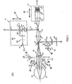
- Fig. 1 is a structural view of an optical system 100 of an eye optical characteristic measuring apparatus.
- the optical system 100 of the eye optical characteristic measuring apparatus is an apparatus for measuring an optical characteristic of an eye 60 to be measured as an object, and includes a first illuminating optical system 10, a first light receiving optical system 20, a second light receiving optical system 30, a common optical system 40, an adjusting optical system 50, a second illuminating optical system 70, and a second light sending optical system 80.
- a retina 61 and a cornea 62 are shown in the drawing.
- the first illuminating optical system 10 includes, for example, a first light source part 11 for emitting a light flux of a first wavelength, and a condensing lens 12, and is for illuminating a minute area on the retina (retina) 61 of the eye 60 to be measured with the light flux from the first light source part 11 so that its illumination condition can be suitably set.
- the first wavelength of the illuminating light flux emitted from the first light source part 11 is a wavelength (for example, 780 nm) of an infrared range.
- the first light source part 11 has a high spatial coherence and a low temporal coherence.
- the first light source part 11 is, for example, a super luminescence diode (SLD), and a point light source having high luminescence can be obtained.
- the first light source part 11 is not limited to the SLD, and for example, a laser having a high spatial coherence and a high temporal coherence can also be used by inserting a rotation diffused plate or the like to suitably lower the temporal coherence.
- an LED having a low spatial coherence and a low temporal coherence can also be used, if light quantity is sufficient, by inserting, for example, a pinhole or the like at a position of a light source in an optical path.
- the first light receiving optical system 20 includes, for example, a collimator lens 21, a Hartmann plate 22 as a conversion member for converting a part of a light flux (first light flux) reflected and returned from the retina 61 of the eye 60 to be measured into at least 17 beams, and a first light receiving part 23 for receiving the plural beams converted by the Hartmann plate 22, and is for guiding the first light flux to the first light receiving part 23.
- a CCD with little readout noise is adopted for the first light receiving part 23, and as the CCD, a suitable type of CCD, for example, a general low noise type of CCD, a cooling CCD of 1000 * 1000 elements for measurement, or the like is applicable.
- the second illuminating optical system 70 includes a second light source 72 and a Placido's disk 71.
- the second light source 72 can be omitted.
- the Placido's disk (PLACIDO'S DISK) 71 is for projecting an index of a pattern composed of plural co-axial rings.
- the index of the pattern composed of the plural co-axial rings is an example of an index of a specified pattern, and a different suitable pattern can be used. Then, after an alignment adjustment described later is completed, the index of the pattern composed of the plural co-axial rings can be projected.
- the second light sending optical system 80 is for mainly performing, for example, the alignment adjustment described later, and measurement and adjustment of a coordinate origin and a coordinate axis, and includes a second light source part 31 for emitting a light flux of a second wavelength, a condensing lens 32, and a beam splitter 33.
- the second light receiving optical system 30 includes a condensing lens 34 and a second light receiving part 35.
- the second light receiving optical system 30 guides a light flux (second light flux), which is originated from the pattern of the Placido's disk 71 illuminated from the second illuminating optical system 70 and is reflected and returned from the anterior eye part or the cornea 62 of the eye 60 to be measured, to the second light receiving part 35.
- a light flux which is emitted from the second light source part 31 and is reflected and returned from the cornea 62 of the eye 60 to be measured, to the second light receiving part 35.
- the second wavelength of the light flux emitted from the second light source part 31 for example, a wavelength different from the first wavelength (here, 780 nm) and longer (for example, 940 nm) than that can be selected.
- the common optical system 40 is disposed on an optical axis of the light flux emitted from the first illuminating optical system 10, can be included in the first and the second illuminating optical systems 10 and 70, the first and the second light receiving optical systems 20 and 30, the second light sending optical system 80 and the like in common, and includes, for example, an afocal lens 42, beam splitters 43 and 45, and a condensing lens 44.
- the beam splitter 43 is formed of such a mirror (for example, a dichroic mirror) that the wavelength of the second light source part 31 is sent (reflected) to the eye 60 to be measured, and the second light flux reflected and returned from the retina 61 of the eye 60 to be measured is reflected, and on the other hand, the wavelength of the first light source part 11 is transmitted.
- the beam splitter 45 is formed of such a mirror (for example, a polarization beam splitter) that the light flux of the first light source part 11 is sent (reflected) to the eye 60 to be measured, and the first light flux reflected and returned from the retina 61 of the eye 60 to be measured is transmitted.
- the adjusting optical system 50 is for mainly performing, for example, a working distance adjustment described later, includes a third light source part 51, a fourth light source part 55, condensing lenses 52 and 53, and a third light receiving part 54, and is for mainly performing the working distance adjustment.
- the third illuminating optical system 90 includes an optical path for projection of an index for causing, for example, fixation of the subject eye or fogging, and includes a fifth light source part (for example, a lamp) 91, a fixed index 92 and a relay lens 93.
- the fixed index 92 can be irradiated to the retina 61 by the light flux from the fifth light source part 91, and the subject eye 60 is made to observe its image.
- the fixed index 92 and the retina 61 are put in a conjugated relation by the third illuminating optical system 90.
- the alignment adjustment is mainly carried out by the second light receiving optical system 30 and the second light sending optical system 80.
- the light flux from the second light source part 31 illuminates the eye 60 to be measured as the object with the substantially parallel light flux through the condensing lens 32, the beam splitters 33 and 43, and the afocal lens 42.
- the reflected light flux reflected by the cornea 62 of the eye 60 to be measured is emitted as a divergent light flux such as is emitted from a point at the half of the radius of curvature of the cornea 62.
- the divergence light flux is received as a spot image by the second light receiving part 35 through the afocal lens 42, the beam splitters 43 and 33, and the condensing lens 34.
- the main body of the eye optical characteristic measuring apparatus is moved and adjusted vertically and horizontally, and the spot image is made to coincide with the optical axis.
- the alignment adjustment is completed.
- the cornea 62 of the eye 60 to be measured is illuminated by the third light source part 51, and an image of the eye 60 to be measured obtained by this illumination is formed on the second light receiving part 35, and accordingly, this image may be used to make the pupil center coincide with the optical axis.
- the working distance adjustment is mainly carried out by the adjusting optical system 50.
- the working distance adjustment is carried out by, for example, irradiating the eye 60 to be measured with a parallel light flux emitted from the fourth light source part 55 and close to the optical axis, and by receiving the light reflected from the eye 60 to be measured through the condensing lenses 52 and 53 by the third light receiving part 54.
- a spot image from the fourth light source part 55 is formed on the optical axis of the third light receiving part 54.
- the spot image from the fourth light source part 55 is formed above or below the optical axis of the third light receiving part 54.
- the third light receiving part 54 since the third light receiving part 54 has only to be capable of detecting a change of a light flux position on the plane containing the fourth light source part 55, the optical axis and the third light receiving part 54, for example, a one-dimensional CCD arranged on this plane, a position sensing device (PSD) or the like is applicable.
- PSD position sensing device
- the beam splitter 45 is inserted in the first light receiving optical system 20, and by this beam splitter 45, the light from the first illuminating optical system 10 is sent to the eye 60 to be measured, and the reflected light from the eye 60 to be measured is transmitted.
- the first light receiving part 23 included in the first light receiving optical system 20 receives the light transmitted through the Hartmann plate 22 as the conversion member and generates a received light signal.
- the first light source part 11 and the retina 61 of the eye 60 to be measured form a conjugated relation.
- the retina 61 of the eye 60 to be measured and the first light receiving part 23 are conjugate.
- the Hartmann plate 22 and the pupil of the eye 60 to be measured form a conjugated relation.
- the front focal point of the afocal lens 42 is substantially coincident with the cornea 62 as the anterior eye part of the eye 60 to be measured and the pupil.
- the first illuminating optical system 10 and the first light receiving optical system 20 are moved together so that a signal peak according to the reflected light at the light receiving part 23 becomes maximum on the condition that the light flux from the first light source part 11 is reflected at a point on which it is condensed. Specifically, the first illuminating optical system 10 and the first light receiving optical system 20 are moved in a direction in which the signal peak at the first light receiving part 23 becomes large, and are stopped at a position where the signal peak becomes maximum. By this, the light flux from the first light source part 11 is condensed on the eye 60 to be measured.
- the lens 12 converts a diffused light of the light source 11 into a parallel light.
- a diaphragm 14 is positioned at an optically conjugated position with respect to the pupil of the eye or the Hartmann plate 22.
- the diaphragm 14 has a diameter smaller than an effective range of the Hartmann plate 22, and the so-called single path aberration measurement (method in which aberrations of an eye have an influence on only the light receiving side) is established.
- the lens 13 is disposed such that the retina conjugated point of the real light beam coincides with the front focal position, and further, in order to satisfy the conjugated relation between the lens and the pupil of the eye, it is disposed such that the rear focal position coincides with the diaphragm 14.
- the beam diameter of the light beam 15 is, for example, about 1 mm at the pupil position of the eye, and the beam diameter of the light beam 24 can be about 7 mm (incidentally, in the drawing, the light beam 15 from the beam splitter 45 to the retina 61 is omitted).
- the Hartmann plate 22 included in the first light receiving optical system 20 is a wavefront conversion member for converting a reflected light flux into plural beams.
- plural micro-Fresnel lenses disposed on a plane orthogonal to the optical axis apply in the Hartmann plate 22.
- the measurement object part the eye 60 to be measured
- in order to measure a sphere of the eye 60 to be measured, third-order astigmatism aberrations, and other higher order aberrations it is necessary to perform the measurement with at least 17 beams through the eye 60 to be measured.
- the micro-Fresnel lens is an optical element, and includes, for example, a ring with a height pitch for each wavelength, and a blade optimized for emission parallel to a condensing point.
- the micro-Fresnel lens here is subjected to, for example, 8-level optical path length variation employing a semiconductor fine working technique, and achieves a high condensing efficiency (for example, 98 %).
- the reflected light from the retina 61 of the eye 60 to be measured passes through the afocal lens 42 and the collimate lens 21 and is condensed on the first light receiving part 23 through the Hartmann plate 22.
- the Hartmann plate 22 includes a wavefront conversion member for converting the reflected light flux into at least 17 beams.
- Fig. 2 is a structural view of an electrical system 200 of the eye optical characteristic measuring apparatus.
- the electrical system 200 of the eye optical characteristic measuring apparatus includes, for example, an arithmetic part 210, a control part 220, a display part 230, a memory 240, a first driving part 250, a second driving part 260, and an input part 270.
- the arithmetic part 210 has an image-data generation part 211, a correction-factor setting part 213, and a determination part 212.
- the arithmetic part 210 receives a received-light signal 4 ⁇ obtained from the first light receiving part 23, a received-light signal 7 ⁇ obtained from the second light receiving part 35, and a received-light signal (10) obtained from the third light receiving part 54, and performs calculations for the origin of coordinates, a coordinate axis, changes in coordinates, rotation, total wavefront aberrations, corneal wavefront aberrations, Zernike coefficients, aberration coefficients, a Strehl ratio, a white-light MTF, a Landolt's ring pattern, and others.
- the arithmetic part 210 also outputs signals corresponding to such calculation results to the control part 220, which controls the entire electric driving system, to the display part 230, and to the memory 240. Details of the operation of the arithmetic part 210 will be described later.
- the image-data generation part 211 simulates how an eyesight test chart target is seen according to measurement data which indicates at least the wavefront aberrations of an eye under examination, with a correction factor for refraction correction being taken into account, to generate target retina image data.
- the wavefront aberrations of the eye under examination includes higher-order aberrations.
- the correction-factor setting part 213 specifies a correction factor to be given to the image-data generation part 211.
- the determination part 212 determines whether the correction factor is appropriate according to corrected target retina image data corrected by the correction factor specified by the correction-factor setting part 213 and generated by the image-data generation part 211.
- the correction-factor setting part 213 sets the correction factor according to the result of the determination part 212, and repeatedly changes the correction factor until the determination part 212 determines that the correction factor is appropriate.
- the correction factor includes one of a spherical power, an astigmatic power, and the angle of an astigmatic axis, or a combination of two or three thereof.
- the correction-factor setting part 213 is configured so as to change the correction factor in the order of the spherical power, the angle of the astigmatic axis, and the astigmatic power
- the determination part 212 is configured so as to determine whether an appropriate correction factor has been set in the order of the spherical power, the angle of the astigmatic axis, and the astigmatic power.
- the image-data generation part 211 can sequentially switch the eyesight test chart target with which the simulation is performed to eyesight test chart targets having different sizes to simulate how the target is seen to generate target retina image data.
- the arithmetic part 210 calculates the luminance spread function Land(x, y) of the Landolt's ring (or any image) by referring to the memory 240 (s205).
- the arithmetic part 210 applies two-dimensional Fourier transform to Land(x, y) to obtain the spatial frequency distribution FR(u, v) (S207).
- the arithmetic part 210 multiplies the spatial frequency distribution FR(u, v) of the Landolt's ring (or any image) by the spatial frequency distribution OTF of the eye, as in the following expression to obtain the frequency distribution OR(u, v) after passing through the eye optical system (S209).
- the arithmetic part 210 determines whether to finish precise measurement (S553). If no, the arithmetic part 210 precisely measures the astigmatic power and the angle of the astigmatic axis (S555).
- S555 as a precise-measurement method, a known technique can be used, if necessary. For example, measurement apparatuses described in Japanese Examined Patent Application Publication No. Hei-5-9092, Japanese Unexamined Patent Application Publication No. Sho-55-151937, and others can be used to precisely measure the astigmatic power and the angle of the astigmatic axis.
- the single-color MTF is calculated from the wavefront aberrations W(x, y).
- W(x, y) is an input value (measured value), and corneal wavefront aberrations obtained from the shape of the cornea can also be used for corneal aberration.
- the pupil function f(x, y) can be determined from the wavefront aberrations in the following way.
- f(x, y) e ikw(x, y) where, i indicates an imaginary number, and k indicates a wave vector (2 ⁇ / ⁇ ).
- the white-color MTF is calculated from the single-color MTF, obtained as described above.
- the white-light MTF is measured only at one wavelength (840 nm)
- calibration may be performed for other wavelengths according to the result of measurement, as compensation, to obtain the MTF at each wavelength. More specifically, when the eye optical characteristic measuring apparatus measures eye aberration, for example, at 840 nm, color aberration W ⁇ (x, y) corresponding to a shift from the wavefront aberrations W 840 (x, y) at a wavelength of 840 nm is measured with the use of an eye model, W 840 (x, y) is added to the color aberration W ⁇ (x, y), and the MTF is calculated at each wavelength from this wavefront aberrations in the following way.
- W ⁇ (x, y) W 840 (x, y) + W ⁇ (x, y)
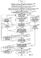
- Fig. 16 is a flowchart of a correction-factor determination method according to a second embodiment. Processes at steps S101 to S105 are the same as in the first embodiment. Then, the arithmetic part 210 calculates correction data for the spherical power (5151). As a specific process thereof, a process described in "4-1. Correction data calculation (spherical power-1)” or “4-2. Correction data calculation (spherical power-2)" can be used.
- the correction-factor setting part 213 of the arithmetic part 210 subtracts a value (in this case, C/2) corresponding to the astigmatic power C from the obtained spherical power S to specify the initial value of the spherical power S. This is performed because the fact that the astigmatic power is obtained at a position where the back focal line is almost on the retina is taken into account.
- the value of C may be obtained from the refractive power or the wavefront aberrations obtained in step S105, or appropriately specified in advance.
- the arithmetic part 210 calculates correction data for the astigmatic components (S153). As a specific process thereof, a process described in "4-3. Correction data calculation (astigmatism-1)", “4-4. Correction data calculation (astigmatism-2)", or "4-5. Correction data calculation (astigmatism-3)" can be used.
- step S109 the arithmetic part 210 outputs data in the same way as in the first embodiment.
- Fig. 17 is a flowchart of a correction-factor determination method according to a third embodiment. Processes at steps S101 to S153 are the same as in the second embodiment. Then, the arithmetic part 210 finely adjusts the spherical power (S161), and in step S109, the arithmetic part 210 outputs data in the same way as in the above-described embodiment.
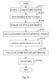
- Fig. 18 shows a flowchart of spherical-power fine adjustment.
- Steps S421, S455, and S457 are the same as those described above.
- step S455 determines in step S455 that detection could be made in the number of directions equal to or more than a half of the specified number of directions. If no, the processing proceeds to step S601, the correction value of the spherical power Ss is slightly changed, and the processes of step S453 and subsequent steps are repeated.
- step S503 the highest visual acuity Vs, the number of directions where detection could be made, nh at the directions where detection could be made are stored in the memory 240 for each Ss, which has been slightly changed.
- the arithmetic part 210 stores data in the memory 240 (S595).
- the arithmetic part 210 stores the results (for example, if the visual acuity is improved when S is increased, then the increased S or if the visual acuity is not changed when S is reduced, then the reduced S), obtained by the fine adjustment performed in step S601.
- the arithmetic part 210 can, for example, pick up spherical powers corresponding to a specified visual acuity or higher from the memory 240, and store in the memory 240 the weakest spherical power corresponding to a specified visual acuity as a value obtained by finely adjusting picked-up data.
- a human observer model for example, is evaluated from a measurement result obtained by an eye-characteristics measuring apparatus capable of measuring even higher-order aberrations, not only when higher-order aberrations, which correspond to a complete objective correction, are used but also when lower-order aberrations are added, a lower-order aberration amount which, for example, improves how an image is seen is calculated, and the data of correction factors such as S, C, and A is obtained at that time to allow a result close to a subjective value to be obtained.
Landscapes
- Health & Medical Sciences (AREA)
- Life Sciences & Earth Sciences (AREA)
- Engineering & Computer Science (AREA)
- Medical Informatics (AREA)
- Surgery (AREA)
- Biophysics (AREA)
- Biomedical Technology (AREA)
- Heart & Thoracic Surgery (AREA)
- Physics & Mathematics (AREA)
- Molecular Biology (AREA)
- Ophthalmology & Optometry (AREA)
- Animal Behavior & Ethology (AREA)
- General Health & Medical Sciences (AREA)
- Public Health (AREA)
- Veterinary Medicine (AREA)
- Signal Processing (AREA)
- Eye Examination Apparatus (AREA)
Abstract
The low-order aberration leading to better visual
acuity is calculated from the results of measurement of an
eye characteristic by an eye characteristic measuring
instrument that can measure up to the high-order
aberration, and data on a correction factor is collected,
thereby obtaining a result more approximate to the
subjective value. According to at least measurement data
representing the wave aberration of the eye being examined
(S401, S403), an image data creating unit creates optotype
retina image data by conducting simulation of the visual
acuity of an optotype (S405), considering the correction
factor for refraction correction. A correction factor
setting unit sets a correction factor to be given to the
image data creating unit (S417). A judging unit judges
from the correction optotype retina image data corrected by
the correction factor whether or not an adequate correction
factor is set (S407 to S421). The correction factor
setting unit sets a correction factor on the basis of the
results of judgment by the judging unit, and changes the
correction factor until the judging unit judges that the
correction factor is adequate.
Description
The present invention relates to correction-factor
determination apparatuses and methods, and more particularly,
to a correction-factor determination apparatus and method for
objectively performing measurement close to a subjective value,
according to wavefront aberrations
Conventionally, as a technology for objectively measuring
the refraction data of an eye, correction factors such as S
(spherical power), C (astigmatic power), and A (angle of an
astigmatic axis) are measured by the use of a refractometer.
In recent years, eye-characteristics measurement apparatuses
capable of measuring even higher-order aberration have been
developed, and therefore, correction factors such as S, C, and
A on a line such as a ring having a diameter of 3 mm used by a
refractometer can be calculated from lower-order aberration.
When such an eye-characteristics measurement apparatus is used,
values closer to subjective values than those obtained by a
refractometer are obtained especially for sick eyes and eyes
on which refractive-power-correction operations have been
performed. The following documents, for example, should be
referenced.
However, there may occur differences between subjective
values and the objective calculation results of conventional
eye-characteristics measurement apparatuses, and insufficient
evaluations may be obtained for correction factors such as S,
C, and A.
Fig. 19 is a view showing a comparison between an
objective examination and a subjective examination.
As shown in the figure, when the objective examination
(objective refraction) and the subjective examination
(subjective refraction) show the same results, the results are
plotted on a line. In actual cases, however, the results of
the examinations may have differences. Especially at a plot
indicated by an arrow, there is a very large difference
between the result of the objective examination, which is
about -15, and the result of the subjective examination, which
is about -7.5.
An object of the present invention is to obtain a result
close to a subjective value by evaluating, for example, a
human observer model from a measurement result obtained by an
eye-characteristics measurement apparatus capable of measuring
higher-order aberrations, not only when only higher-order
aberrations, which correspond to a complete objective
correction, are used but also when lower-order aberrations are
added, by calculating, for example, a lower-order aberration
amount which improves how an image is seen, and by obtaining
data of correction factors such as S, C, and A at that time.
According to the first solving means of this invention,
there is provided a correction-factor determination apparatus
comprising:
According to the second solving means of this invention,
there is provided a correction-factor determination method
including:
According to the third solving means of this invention,
there is provided a correction-factor determination method
including:
Fig. 1 is a structural view of an optical system 100 of
an eye optical characteristic measuring apparatus.
The optical system 100 of the eye optical characteristic
measuring apparatus is an apparatus for measuring an optical
characteristic of an eye 60 to be measured as an object, and
includes a first illuminating optical system 10, a first light
receiving optical system 20, a second light receiving optical
system 30, a common optical system 40, an adjusting optical
system 50, a second illuminating optical system 70, and a
second light sending optical system 80. Incidentally, with
respect to the eye 60 to be measured, a retina 61 and a cornea
62 are shown in the drawing.
The first illuminating optical system 10 includes, for
example, a first light source part 11 for emitting a light
flux of a first wavelength, and a condensing lens 12, and is
for illuminating a minute area on the retina (retina) 61 of
the eye 60 to be measured with the light flux from the first
light source part 11 so that its illumination condition can be
suitably set. Incidentally, here, as an example, the first
wavelength of the illuminating light flux emitted from the
first light source part 11 is a wavelength (for example, 780
nm) of an infrared range.
Besides, it is desirable that the first light source part
11 has a high spatial coherence and a low temporal coherence.
Here, the first light source part 11 is, for example, a super
luminescence diode (SLD), and a point light source having high
luminescence can be obtained. Incidentally, the first light
source part 11 is not limited to the SLD, and for example, a
laser having a high spatial coherence and a high temporal
coherence can also be used by inserting a rotation diffused
plate or the like to suitably lower the temporal coherence.
Further, an LED having a low spatial coherence and a low
temporal coherence can also be used, if light quantity is
sufficient, by inserting, for example, a pinhole or the like
at a position of a light source in an optical path.
The first light receiving optical system 20 includes, for
example, a collimator lens 21, a Hartmann plate 22 as a
conversion member for converting a part of a light flux (first
light flux) reflected and returned from the retina 61 of the
eye 60 to be measured into at least 17 beams, and a first
light receiving part 23 for receiving the plural beams
converted by the Hartmann plate 22, and is for guiding the
first light flux to the first light receiving part 23. Besides,
here, a CCD with little readout noise is adopted for the first
light receiving part 23, and as the CCD, a suitable type of
CCD, for example, a general low noise type of CCD, a cooling
CCD of 1000 * 1000 elements for measurement, or the like is
applicable.
The second illuminating optical system 70 includes a
second light source 72 and a Placido's disk 71. Incidentally,
the second light source 72 can be omitted. The Placido's disk
(PLACIDO'S DISK) 71 is for projecting an index of a pattern
composed of plural co-axial rings. Incidentally, the index of
the pattern composed of the plural co-axial rings is an
example of an index of a specified pattern, and a different
suitable pattern can be used. Then, after an alignment
adjustment described later is completed, the index of the
pattern composed of the plural co-axial rings can be projected.
The second light sending optical system 80 is for mainly
performing, for example, the alignment adjustment described
later, and measurement and adjustment of a coordinate origin
and a coordinate axis, and includes a second light source part
31 for emitting a light flux of a second wavelength, a
condensing lens 32, and a beam splitter 33.
The second light receiving optical system 30 includes a
condensing lens 34 and a second light receiving part 35. The
second light receiving optical system 30 guides a light flux
(second light flux), which is originated from the pattern of
the Placido's disk 71 illuminated from the second illuminating
optical system 70 and is reflected and returned from the
anterior eye part or the cornea 62 of the eye 60 to be
measured, to the second light receiving part 35. Besides, it
can also guide a light flux, which is emitted from the second
light source part 31 and is reflected and returned from the
cornea 62 of the eye 60 to be measured, to the second light
receiving part 35. Incidentally, as the second wavelength of
the light flux emitted from the second light source part 31,
for example, a wavelength different from the first wavelength
(here, 780 nm) and longer (for example, 940 nm) than that can
be selected.
The common optical system 40 is disposed on an optical
axis of the light flux emitted from the first illuminating
optical system 10, can be included in the first and the second
illuminating optical systems 10 and 70, the first and the
second light receiving optical systems 20 and 30, the second
light sending optical system 80 and the like in common, and
includes, for example, an afocal lens 42, beam splitters 43
and 45, and a condensing lens 44. The beam splitter 43 is
formed of such a mirror (for example, a dichroic mirror) that
the wavelength of the second light source part 31 is sent
(reflected) to the eye 60 to be measured, and the second light
flux reflected and returned from the retina 61 of the eye 60
to be measured is reflected, and on the other hand, the
wavelength of the first light source part 11 is transmitted.
The beam splitter 45 is formed of such a mirror (for example,
a polarization beam splitter) that the light flux of the first
light source part 11 is sent (reflected) to the eye 60 to be
measured, and the first light flux reflected and returned from
the retina 61 of the eye 60 to be measured is transmitted. By
the beam splitters 43 and 45, the first and the second light
fluxes do not mutually enter the other optical systems to
generate noise.
The adjusting optical system 50 is for mainly performing,
for example, a working distance adjustment described later,
includes a third light source part 51, a fourth light source
part 55, condensing lenses 52 and 53, and a third light
receiving part 54, and is for mainly performing the working
distance adjustment.
The third illuminating optical system 90 includes an
optical path for projection of an index for causing, for
example, fixation of the subject eye or fogging, and includes
a fifth light source part (for example, a lamp) 91, a fixed
index 92 and a relay lens 93. The fixed index 92 can be
irradiated to the retina 61 by the light flux from the fifth
light source part 91, and the subject eye 60 is made to
observe its image. The fixed index 92 and the retina 61 are
put in a conjugated relation by the third illuminating optical
system 90.
Next, the alignment adjustment will be described. The
alignment adjustment is mainly carried out by the second light
receiving optical system 30 and the second light sending
optical system 80.
First, the light flux from the second light source part
31 illuminates the eye 60 to be measured as the object with
the substantially parallel light flux through the condensing
lens 32, the beam splitters 33 and 43, and the afocal lens 42.
The reflected light flux reflected by the cornea 62 of the eye
60 to be measured is emitted as a divergent light flux such as
is emitted from a point at the half of the radius of curvature
of the cornea 62. The divergence light flux is received as a
spot image by the second light receiving part 35 through the
afocal lens 42, the beam splitters 43 and 33, and the
condensing lens 34.
Here, in the case where the spot image on the second
light receiving part 35 is outside the optical axis, the main
body of the eye optical characteristic measuring apparatus is
moved and adjusted vertically and horizontally, and the spot
image is made to coincide with the optical axis. As stated
above, when the spot image coincides with the optical axis,
the alignment adjustment is completed. Incidentally, with
respect to the alignment adjustment, the cornea 62 of the eye
60 to be measured is illuminated by the third light source
part 51, and an image of the eye 60 to be measured obtained by
this illumination is formed on the second light receiving part
35, and accordingly, this image may be used to make the pupil
center coincide with the optical axis.
Next, the working distance adjustment will be described.
The working distance adjustment is mainly carried out by the
adjusting optical system 50.
First, the working distance adjustment is carried out by,
for example, irradiating the eye 60 to be measured with a
parallel light flux emitted from the fourth light source part
55 and close to the optical axis, and by receiving the light
reflected from the eye 60 to be measured through the
condensing lenses 52 and 53 by the third light receiving part
54. Besides, in the case where the eye 60 to be measured is in
a suitable working distance, a spot image from the fourth
light source part 55 is formed on the optical axis of the
third light receiving part 54. On the other hand, in the case
where the eye 60 to be measured goes out of the suitable
working distance, the spot image from the fourth light source
part 55 is formed above or below the optical axis of the third
light receiving part 54. Incidentally, since the third light
receiving part 54 has only to be capable of detecting a change
of a light flux position on the plane containing the fourth
light source part 55, the optical axis and the third light
receiving part 54, for example, a one-dimensional CCD arranged
on this plane, a position sensing device (PSD) or the like is
applicable.
Next, a positional relation between the first
illuminating optical system 10 and the first light receiving
optical system 20 will be described.
The beam splitter 45 is inserted in the first light
receiving optical system 20, and by this beam splitter 45, the
light from the first illuminating optical system 10 is sent to
the eye 60 to be measured, and the reflected light from the
eye 60 to be measured is transmitted. The first light
receiving part 23 included in the first light receiving
optical system 20 receives the light transmitted through the
Hartmann plate 22 as the conversion member and generates a
received light signal.
Besides, the first light source part 11 and the retina 61
of the eye 60 to be measured form a conjugated relation. The
retina 61 of the eye 60 to be measured and the first light
receiving part 23 are conjugate. Besides, the Hartmann plate
22 and the pupil of the eye 60 to be measured form a
conjugated relation. Further, the front focal point of the
afocal lens 42 is substantially coincident with the cornea 62
as the anterior eye part of the eye 60 to be measured and the
pupil.
Besides, the first illuminating optical system 10 and the
first light receiving optical system 20 are moved together so
that a signal peak according to the reflected light at the
light receiving part 23 becomes maximum on the condition that
the light flux from the first light source part 11 is
reflected at a point on which it is condensed. Specifically,
the first illuminating optical system 10 and the first light
receiving optical system 20 are moved in a direction in which
the signal peak at the first light receiving part 23 becomes
large, and are stopped at a position where the signal peak
becomes maximum. By this, the light flux from the first light
source part 11 is condensed on the eye 60 to be measured.
Besides, the lens 12 converts a diffused light of the
light source 11 into a parallel light. A diaphragm 14 is
positioned at an optically conjugated position with respect to
the pupil of the eye or the Hartmann plate 22. The diaphragm
14 has a diameter smaller than an effective range of the
Hartmann plate 22, and the so-called single path aberration
measurement (method in which aberrations of an eye have an
influence on only the light receiving side) is established. In
order to satisfy the above, the lens 13 is disposed such that
the retina conjugated point of the real light beam coincides
with the front focal position, and further, in order to
satisfy the conjugated relation between the lens and the pupil
of the eye, it is disposed such that the rear focal position
coincides with the diaphragm 14.
Besides, after a light beam 15 comes to have a light path
common to a light beam 24 by the beam splitter 45, it travels
in the same way as the light beam 24 paraxially. However, in
the single path measurement, the diameters of the light beams
are different from each other, and the beam diameter of the
light beam 15 is set to be rather small as compared with the
light beam 24. Specifically, the beam diameter of the light
beam 15 is, for example, about 1 mm at the pupil position of
the eye, and the beam diameter of the light beam 24 can be
about 7 mm (incidentally, in the drawing, the light beam 15
from the beam splitter 45 to the retina 61 is omitted).
Next, the Hartmann plate 22 as the conversion member will
be described.
The Hartmann plate 22 included in the first light
receiving optical system 20 is a wavefront conversion member
for converting a reflected light flux into plural beams. Here,
plural micro-Fresnel lenses disposed on a plane orthogonal to
the optical axis apply in the Hartmann plate 22. Besides, in
general, with respect to the measurement object part (the eye
60 to be measured), in order to measure a sphere of the eye 60
to be measured, third-order astigmatism aberrations, and other
higher order aberrations, it is necessary to perform the
measurement with at least 17 beams through the eye 60 to be
measured.
Besides, the micro-Fresnel lens is an optical element,
and includes, for example, a ring with a height pitch for each
wavelength, and a blade optimized for emission parallel to a
condensing point. The micro-Fresnel lens here is subjected to,
for example, 8-level optical path length variation employing a
semiconductor fine working technique, and achieves a high
condensing efficiency (for example, 98 %).
Besides, the reflected light from the retina 61 of the
eye 60 to be measured passes through the afocal lens 42 and
the collimate lens 21 and is condensed on the first light
receiving part 23 through the Hartmann plate 22. Accordingly,
the Hartmann plate 22 includes a wavefront conversion member
for converting the reflected light flux into at least 17 beams.
Fig. 2 is a structural view of an electrical system 200
of the eye optical characteristic measuring apparatus. The
electrical system 200 of the eye optical characteristic
measuring apparatus includes, for example, an arithmetic part
210, a control part 220, a display part 230, a memory 240, a
first driving part 250, a second driving part 260, and an
input part 270. The arithmetic part 210 has an image-data
generation part 211, a correction-factor setting part 213, and
a determination part 212.
The arithmetic part 210 receives a received-light signal
4 ○ obtained from the first light receiving part 23, a received-light
signal 7 ○ obtained from the second light receiving part
35, and a received-light signal (10) obtained from the third
light receiving part 54, and performs calculations for the
origin of coordinates, a coordinate axis, changes in
coordinates, rotation, total wavefront aberrations, corneal
wavefront aberrations, Zernike coefficients, aberration
coefficients, a Strehl ratio, a white-light MTF, a Landolt's
ring pattern, and others. The arithmetic part 210 also
outputs signals corresponding to such calculation results to
the control part 220, which controls the entire electric
driving system, to the display part 230, and to the memory 240.
Details of the operation of the arithmetic part 210 will be
described later.
The image-data generation part 211 simulates how an
eyesight test chart target is seen according to measurement
data which indicates at least the wavefront aberrations of an
eye under examination, with a correction factor for refraction
correction being taken into account, to generate target retina
image data. The wavefront aberrations of the eye under
examination includes higher-order aberrations. The
correction-factor setting part 213 specifies a correction
factor to be given to the image-data generation part 211. The
determination part 212 determines whether the correction
factor is appropriate according to corrected target retina
image data corrected by the correction factor specified by the
correction-factor setting part 213 and generated by the image-data
generation part 211. The correction-factor setting part
213 sets the correction factor according to the result of the
determination part 212, and repeatedly changes the correction
factor until the determination part 212 determines that the
correction factor is appropriate. The correction factor
includes one of a spherical power, an astigmatic power, and
the angle of an astigmatic axis, or a combination of two or
three thereof.
It is possible that the correction-factor setting part
213 is configured so as to change the correction factor in the
order of the spherical power, the angle of the astigmatic axis,
and the astigmatic power, and the determination part 212 is
configured so as to determine whether an appropriate
correction factor has been set in the order of the spherical
power, the angle of the astigmatic axis, and the astigmatic
power. When the spherical power and/or the astigmatic power
is selected as the correction factor, the image-data
generation part 211 can sequentially switch the eyesight test
chart target with which the simulation is performed to
eyesight test chart targets having different sizes to simulate
how the target is seen to generate target retina image data.
When it is determined whether the spherical power or the
astigmatic power is appropriate, the eyesight test chart
target with which the image-data generation part 211 performs
the simulation can, for example, be a Landolt's ring target.
A letter target or a natural image may be effective in some
cases. A contrast target may be used.
The determination part 212 can be configured so as to
compare matching pattern data of a certain eyesight test chart
target with the target retina image data obtained in the
simulation to obtain the degree of correlation to determine
whether the correction factor is appropriate. In this case,
the determination part 212 can, for example, apply two-dimensional
Fourier transform to the spatial frequency of a
template and multiply the resultant by the spatial-frequency
distribution of an retina image to perform determination by
template matching. The image-data generation part 211 can be
configured so as to calculate a pupil function from the
wavefront aberrations, to calculate the luminance distribution
function of a visual-acuity target, to multiply the function
by the spatial-frequency distribution of the eye, and to apply
two-dimensional inverse Fourier transform to the resultant to
obtain target retina image data obtained by simulating
measurement data indicating the refractive-power distribution
of the eye under measurement, and/or the target retina image
data corrected by the specified correction factor.
It is also possible that the image-data generation part
211 is configured so as to generate MTF data as the simulation
of how the eyesight test chart target is seen, with
measurement data indicating at least the wavefront aberrations
of the eye under measurement and a correction factor for
refraction correction being taken into account, and the
determination part 212 is configured so as to determine
according to the generated MTF data whether the correction
factor is appropriate.
The correction-factor setting part 213 can be configured
so as to perform correction from a weak correction point in
usual cases. The correction-factor setting part 213 can also
be configured so as to perform correction according to a
subjective-measurement procedure.
The control part 220 controls lighting and extinction of
the first light source part 11 on the basis of the control
signal from the arithmetic part 210, or controls the first
driving part 250 and the second driving part 260. For example,
on the basis of the signals corresponding to the operation
results in the arithmetic part 210, the control part outputs a
signal (1) to the first light source part 11, outputs a signal
(5) to the Placido's disk 71, outputs a signal (6) to the
second light source part 31, outputs a signal (8) to the third
light source part 51, outputs a signal (9) to the fourth light
source part 55, outputs a signal (11) to the fifth light
source part 91, and outputs signals to the first driving part
250 and the second driving part 260.
The first driving part 250 is for moving the whole first
illuminating optical system 10 in the optical axis direction
on the basis of, for example, the received light signal (4)
inputted to the arithmetic part 210 from the first light
receiving part 23, and outputs a signal (2) to a not-shown
suitable lens movement means and drives the lens movement
means. By this, the first driving part 250 can perform the
movement and adjustment of the first illuminating optical
system 10.
The second driving part 260 is for moving the whole first
light receiving optical system 20 in the optical axis
direction on the basis of, for example, the received light
signal (4) inputted to the arithmetic part 210 from the first
light receiving part 23, and outputs a signal (3) to a not-shown
suitable lens movement means, and drives the lens
movement means. By this, the second driving part 260 can
perform the movement and adjustment of the first light
receiving optical system 20.
Next, a Zernike analysis will be described. A generally
known method of calculating Zernike coefficients Ci 2j-i from
Zernike polynomials will be described. The Zernike
coefficients Ci 2j-i are important parameters for grasping the
optical characteristic of the subject eye 60 on the basis of
inclination angles of the light fluxes obtained by the first
light receiving part 23 through the Hartmann plate 22.
Wavefront aberrations W(X, Y) of the subject eye 60 are
expressed using the Zernike coefficients Ci 2j-i and the Zernike
polynomials Zi 2j-i by the following expression.

Where, (X, Y) denotes vertical and horizontal coordinates
of the Hartmann plate 22.
Besides, with respect to the wavefront aberrations W(X,
Y), when the horizontal and vertical coordinates of the first
light receiving part 23 are denoted by (x, y), a distance
between the Hartmann plate 22 and the first light receiving
part 23 is denoted by f, and a movement distance of a point
image received by the first light receiving part 23 is denoted
by (Δx, Δy), the following expression is established.
∂W (X ,Y )∂X = Δx f
∂W (X ,Y ) ∂Y =Δy f
Where, the Zernike polynomials Zi 2j-i are expressed by the
following numerical expressions.
Fig. 3 is a view of the Zernike coefficients of (r, t)
coordinates, and Fig. 4 is a view of the Zernike coefficients
of (x, y) coordinates. Specifically, Zernike polynomials Zi 2j-i
are expressed by these figures.
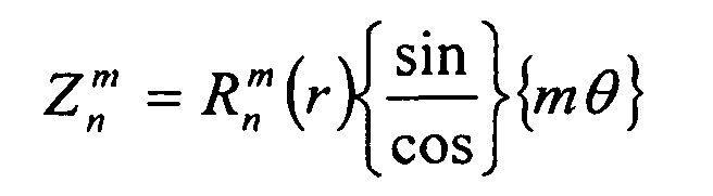
m>0 sin
m≦0 cos

Incidentally, with respect to the Zernike coefficients
Ci 2j-i, specific values can be obtained by minimizing the
squared error expressed by the following numerical expression.

Where, W(X, Y): wavefront aberrations, (X, Y): Hartmann
plate coordinates, (Δx, Δy): a movement distance of a point
image received by the first light receiving part 23, f: a
distance between the Hartmann plate 22 and the first light
receiving part 23, m: the number of data.
The arithmetic part 210 calculates the Zernike
coefficients Ci 2j-i, and uses this to obtain eye optical
characteristics such as spherical aberrations, coma
aberrations, and astigmatism aberrations. The arithmetic part
210 calculates a spherical power of the eye to be measured
based on a moving amount of the first light receiving optical
system and the wavefront aberrations.
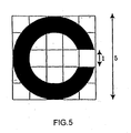
Fig. 5 is an explanatory view of a Landolt's ring.
Hereinafter, preparation of data of a luminous
distribution function Land(x, y) of the Landolt's ring will be
described.
The Landolt's ring is expressed by the reciprocal of a
recognizable minimum visual angle, and the ability to be
capable of recognizing a visual angle of one minute is called
visual acuity of 20/20. For example, if the recognizable
minimum visual angle is 2 minutes, the visual acuity is
defined as 20/40, and if 10 minutes, the visual acuity is
defined as 20/200. In general, the Landolt's ring uses, as an
index, a ring in which a gap being 1/5 of the size of the
outside ring is provided as shown in the drawing.
When the visual acuity is V, the size d of the Landolt's
ring projected on the retina is calculated by
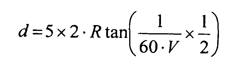 (R: a distance between a pupil and an image point (retina))
On the basis of this expression and the definition of the
Landolt's ring, a black portion of the Landolt's ring is made
0, a white portion thereof is made 1, and the luminous
distribution function Land(x, y) of the Landolt's ring is
prepared. The data of the prepared luminous distribution
function Land(x, y) is stored in the memory 240, is read out
by the arithmetic part 210, and is set correspondingly to
predetermined visual acuity.
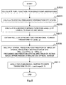
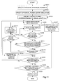
Fig. 6 is a flowchart of a correction-factor
determination method according to a first embodiment.
The eye-characteristic measuring apparatus first aligns
the X, Y, and Z axes at the pupil position of the eye under
measurement (S101). The measuring apparatus next moves the
movable block to its origin (S103). For example, the Hartmann
plate and the Placido's ring are adjusted to a diopter of zero.
The arithmetic part 210 measures eye optical-system data such
as the total wavefront aberrations and the Zernike
coefficients according to the measured received-light signals
4 ○, 7 ○, and/or (10) (S105). The arithmetic part 210 simulates
how the eyesight test chart target is seen and generates
target retina image data to calculate correction data
(correction factor) (S107). The correction factor includes
one of the spherical power (S), the astigmatic power (C), and
the angle (A) of the astigmatic axis, or a combination of two
or three thereof. Details of this processing will be
described later. The arithmetic part 10 outputs the
correction factor, image simulation data corrected with the
correction factor, and others to the display part 230 and to
the memory 240 (S109).
A specific display example will be described below.
When a correction value is obtained by the above-described
method, visual-acuity-chart simulation can be
performed according to a spherical power, an astigmatic power,
and the angle of an astigmatic axis serving as correction
means and input, for example, through a user interface such as
a dialog box, and a measured spherical power (the diopter
value when de-focused is equal to the measured spherical power
minus the spherical power serving as correction means), a
measured astigmatic power, a measured angle (astigmatic
contribution to wavefront aberrations in simulation is equal
to wavefront aberrations caused by a measured astigmatic
amount minus wavefront aberrations caused by an astigmatic
amount serving as correction means) of the astigmatic axis,
and higher-order aberrations, and the simulation result can be
displayed.
In this simulation, not only the original target image
used for estimating the correction value but also Landolt's
rings having different powers and other letter targets such as
the whole Snellen letter target can be used. In order for the
user to use a desired target or a target similar thereto as
the original image for simulation, simulation can be applied
to a target image desired by the user and input with a scanner,
input image data such as bitmap data, or data input to a
target drawn by using a drawing program or a mechanical-design
CAD program, and the simulation result can be displayed. A
natural image is a part of desired targets.
In a display example of a simulation result, as shown in
Fig. 20, target retina images obtained by simulation are
displayed which uses a correction factor which makes best the
Strehl ratio based on a measurement for the wavefront
aberrations of the eye under measurement, a correction factor
obtained by a result of an auto-refractometer measurement, a
correction factor obtained by subjective eyesight examination
and input if necessary, and correction data obtained by the
processing described in the present embodiment. The display
area shown in Fig. 20 includes all of various correction
factors, but a display area which includes some of the
correction factors may be used. The display area can also be
specified by inputting one of the spherical power, the
astigmatic power, and the angle of the astigmatism axis with
its range. This function is very useful for research on
presbyopia and adjustment functions because the function can
be used for final confirmation and can also make definite what
kind of optical characteristics the eye has in a depth
direction.
The display can be applied not only to retina-image
simulation but also to a spatial-frequency characteristic
(MTF) and a point spread function (PSF) (Fig. 21(A)). MTF at
a specified spatial frequency, the Strehl ratio of the point
spread function, or others can be output, for example, in a
range where the spherical power has been input (Fig. 21(B)).
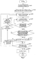
Fig. 7 is a flowchart of correction-data calculation
(spherical power-1).
The arithmetic part 210 calculates a tentative spherical
power Sr (S401). As the spherical power Sr, a refractive
power or a value calculated from the wavefront aberrations may
be used, for example. Alternatively, a value stored in the
memory 240 in advance or a value input from the input part may
also be used.
Then, the arithmetic part 210 specifies a spherical power
Ss used in simulation, and the size of a Landolt's ring (S403).
Usually, Ss is set weaker in correction (more nearsighted as a
result) than Sr (for example, Ss = Sr + 5D). For example, the
size of a Landolt's ring can be calculated from Sr, if
necessary, or it is possible that a correspondence table
having stored Sr, other correction factors, or Zernike
coefficients and corresponding visual acuity is stored in the
memory 240 in advance and the arithmetic part 210 references
it to determine the size of a Landolt's ring.
Then, the image-data generation part 211 of the
arithmetic part 210 performs Landolt's-ring retina image
simulation to obtain target retina image data (S405). The
image-data generation part 211 first applies simulation to the
Landolt's ring in a direction specified in advance (such as a
ring having an opening in the upper, lower, right, or left
direction). More specifically, the image-data generation part
211 obtains target retina image data which indicates how the
Landolt's ring is seen, by simulation according to the
wavefront aberrations measured in step S105. Specific
simulation processing will be described later.
Next, the determination part 212 of the arithmetic part
210 performs Landolt's-ring template matching (S407). The
determination part 212 performs template matching between the
target retina image data obtained by the simulation and the
Landolt's ring in a certain direction, and stores the
direction and a score "n" which indicates the matching degree
in the memory 240. A specific process will be described later.
The determination part 212 determines (S409) whether
template matching has been performed in all directions of the
Landolt's ring template. If no, the processing proceeds to
step S407, and the matching process is repeated until template
matching has been performed in all directions. When yes in
step S409, the determination part 212 determines (411) whether
the direction of the opening of the Landolt's ring used when
the highest score nh is obtained matches the direction of the
opening of the Landolt's ring of the target retina image data
in the simulation. If yes, the determination part 212
determines (S413) whether the score nh is higher than a
threshold specified in advance in the memory 240 or others.
If no in step S411 or step S413, the determination part
212 determines (S415) whether Ss exceeds an allowance (for
example, Sr - 5D) specified in advance. If no, the
correction-factor setting part 213 sets the Ss correction
factor slightly stronger (for example, Ss = Ss - 0.25D) (S417),
and the image-data generation part 211 performs Landolt's-ring
retina image simulation according to this correction factor.
The processes of step S407 and subsequent steps are executed
for the target retina image data obtained by the simulation.
When yes is step S415, the determination part 212 determines
(S419) that the Landolt's ring cannot be detected, and stores
the direction and the fact that the Landolt's ring cannot be
detected in the direction, in the memory 240.
After step S419, or when yes in step S413, the
determination part 212 determines (S421) whether simulation
has been performed in all directions of the simulation
Landolt's ring. If no, the processing returns to step S405,
and the arithmetic part 210 repeats the above-described
processes in all directions. When yes in step S421, the
arithmetic part 210 outputs data (S423). More specifically,
the arithmetic part 210 displays, for example, the spherical
power S = Ss, the direction of the Landolt's ring which could
be detected, the size of the Landolt's ring, simulation
results, and others on the display part 230, and stores them
in the memory 240.
Fig. 8 is a flowchart of the retina image simulation
performed in step S405 described above.
The arithmetic part 210 calculates a pupil function f(x,
y) by the following expression (S203) from the wavefront
aberrations W(x, y) obtained in step S105.

f (x, y) = e i k W (x, y)
where i indicates an imaginary number, k indicates a wave
vector of 2π/λ, and λ indicates a wavelength.
Next, the spatial frequency distribution OTF of the eye
is obtained in step S204. The arithmetic part 210 applies the
Fourier transform to the pupil function f(x, y) to obtain the
point spread function U(u, v) by amplitude as in the following
expression.
 where, λ indicates a wavelength, R indicates the distance from
the pupil to the image point (retina), (u, v) indicates
coordinates in the plane perpendicular to the optical axis and
having the image point O as the origin, and (x, y) indicates
coordinates in the pupil plane.
where, λ indicates a wavelength, R indicates the distance from
the pupil to the image point (retina), (u, v) indicates
coordinates in the plane perpendicular to the optical axis and
having the image point O as the origin, and (x, y) indicates
coordinates in the pupil plane.
The arithmetic part 210 multiplies U(u, v) by its complex
conjugate to obtain the point spread function (PSF) I(u, v) by
the following expression.
I(u, v) = U(u, v)U*(u, v)
Then, the arithmetic part 210 applies the Fourier
transform (or self correlation) to PSF to standardize it to
obtain OTF as in the following expression.

OTF = R(r,s)R(0,0)
The arithmetic part 210 calculates the luminance spread
function Land(x, y) of the Landolt's ring (or any image) by
referring to the memory 240 (s205). The arithmetic part 210
applies two-dimensional Fourier transform to Land(x, y) to
obtain the spatial frequency distribution FR(u, v) (S207).
The arithmetic part 210 multiplies the spatial frequency
distribution FR(u, v) of the Landolt's ring (or any image) by
the spatial frequency distribution OTF of the eye, as in the
following expression to obtain the frequency distribution OR(u,
v) after passing through the eye optical system (S209).
FR(u, v) x OTF(u, v) ---> OR(u, v)
FR(u, v) x OTF(u, v) ---> OR(u, v)
Next, the arithmetic part 210 applies two-dimensional
inverse Fourier transform to OR(u, v) to obtain the luminance
spread image LandImage(X, Y) of the Landolt's ring (or any
image) (S211). The arithmetic part 210 appropriately displays
LandImage(X, Y), PSF(X, Y), and others on the display part 230
by an appropriate method, such as by figures, graphic data,
graphs, and/or numerals, and appropriately stores the data in
the memory 240.
Fig. 9 shows an explanatory view indicating the template
matching performed in step S407 described above.
As shown in the figure, a template image (lower image) is
specified correspondingly to the original Landolt's ring image
(upper image), and the template image is stored in association
with an identifier indicating the size of the Landolt's ring,
in the memory 240. In this example, in the template image, b
= 1.5a, the number of pixels at a Landolt's-ring block is set
to N1, their pixel value is set to 1, the number of pixels at
a blurred-point-image block around the Landolt's-ring block is
set to N2, and their pixel value is set to -N1/N2. The
template image is not limited to this example, and can be
appropriately specified.
Fig. 10 is a flowchart of the template matching.
The arithmetic part 210 reads the template image
according to the specified size of the Landolt's ring from the
memory 240, and obtains its spatial frequency distribution
Temp(x, y) (S301). Then, the arithmetic part 210 applies two-dimensional
Fourier transform to Temp(x, y) to obtain FT(u, v)
(S303). The arithmetic part 210 applies two-dimensional
Fourier transform to the spatial frequency distribution of the
target retina image data obtained by retina-image simulation
to obtain OR(u, v), and multiplies OR(u, v) by the spatial
frequency distribution FT(u, v) of the template, as in the
following expression, to obtain OTmp(u, v) (S305).
OR(u, v) x FT(u, v) ---> OTmp(u, v)
OR(u, v) x FT(u, v) ---> OTmp(u, v)
The arithmetic part 210 applies two-dimensional inverse
Fourier transform to OTmp(u, v) to obtain TmpIm(X, Y) (4a by
4a complex-number matrix) (S307). The arithmetic part 210
obtains the maximum value of the absolute values of TmpIm(X,
Y), and sets it as a score "n" (S309).
With such correlation, when the simulation target image
is close to the original image, a high score is obtained. If
the simulation target image is blurred, the score becomes
lower accordingly.
Fig. 11 is a flowchart of correction-data calculation
(spherical power-2). In each of the following flow charts,
the same processes are executed in steps having the same
symbols.
The arithmetic part 210 calculates a tentative spherical
power Sr (S401). The calculation is the same as in step S401
described in "4-1. Correction data calculation: spherical
power (1)". Then, the arithmetic part 210 specifies a
spherical power Ss used in simulation (S451). Usually, Ss is
set weaker in correction than Sr (for example, Ss = Sr + 5D).
The arithmetic part 210 specifies a Landolt's ring (S453)
corresponding to visual acuity (for example, Vs = 1.0)
specified in advance.
In steps S405 to S421, the arithmetic part 210 performs
processes such as Landolt's-ring retina image simulation and
Landolt's-ring template matching in the same way as in the
steps having the same symbols in "4-1. Correction data
calculation: spherical power (1)".
In step S421, when the determination part 212 of the
arithmetic part 210 determines that simulation has been
performed in all directions, the determination part 212
further determines whether detection could be made in the
number of directions equal to or more than a half of the
specified number of directions (S455). When yes in step S455,
the correction-factor setting part 213 sets S = Ss and V = Vs,
and specifies a Landolt's ring corresponding to visual acuity
Vs = Vs + 0.1 (S457). Then, the processing proceeds to step
S405, and the image-data generation part 211 performs retina-image
simulation according to the specified correction factor
and Landolt's ring to obtain target image data, and the
processes of step S407 and subsequent steps are executed.
When no in step S455, the arithmetic part 210 outputs data
(S423). More specifically, the arithmetic part 210 displays,
for example, the current spherical power S = Ss, the detected
direction of the Landolt's ring, the size V of the Landolt's
ring, and simulation results on the display part 230, and
stores them in the memory 240.
Fig. 12 and Fig. 13 show a flowchart of correction-data
calculation (astigmatism-1).
The arithmetic part 210 calculates a tentative spherical
power Sr (S401) as in step S401 described above. Then, the
arithmetic part 210 specifies an astigmatic power Cs used in
simulation (S501). For example, Cs may be set to 0, an
astigmatic power C calculated from the refractive power or the
wavefront aberrations may be used, or Cs may be obtained by
referring to a correspondence table having stored Cs in
association with a correction factor such as S or C, or
Zernike coefficients, stored in advance in the memory 240.
The arithmetic part 210 specifies a Landolt's ring (S453)
corresponding to visual acuity (for example, Vs = 0.1).
In steps S405 to S413, the arithmetic part 210 performs
processes such as Landolt's-ring retina image simulation and
Landolt's-ring template matching in the same way as described
above.
When no in step S411 or step S413, the determination part 212 determines that the Landolt's ring cannot be detected, and stores the direction and the fact that the Landolt's ring cannot be detected in the direction, in thememory 240.
When no in step S411 or step S413, the determination part 212 determines that the Landolt's ring cannot be detected, and stores the direction and the fact that the Landolt's ring cannot be detected in the direction, in the
After step S419, or when yes in step S413, the arithmetic
part 210 executes the processes of steps S421 and S455 in the
same way as described above.
When it is determined in step S455 that detection could
be made in the number of directions equal to or more than a
half of the specified number of directions, the arithmetic
part 210 stores the specified correction factor in the memory
240 (S503). Then, the correction-factor setting part 213 sets
V = Vs, and specifies a Landolt's ring corresponding to visual
acuity Vs = Vs + 0.1 (S505). Then, the processing proceeds to
step S405, and the image-data generation part 211 performs
retina-image simulation according to the specified correction
factor and Landolt's ring to obtain target image data, and the
processes of step S407 and subsequent steps are executed.
When no in step S455, the determination part 212
determines (S507) whether simulation has been performed in all
astigmatism-axis angles (0 to 180). If no, the correction-factor
setting part 213 rotates the astigmatism-axis angle As
(for example, As = As + 5) (S509). Then, the processing
proceeds to step S453, and the processes of step S453 and
subsequent steps are repeatedly executed.
Next, by referring to Fig. 13, when the determination
part 212 obtains yes in step S507, the correction-factor
setting part 213 of the arithmetic part 210 substitutes As
where the highest visual acuity V is obtained, for the
astigmatic-axis angle A (S511). When there is a plurality of
As's where the highest visual acuity V is obtained, As where
the largest number of Landolt's rings can be detected at the
visual acuity V is substituted for the astigmatic-axis angle A.
When there is also a plurality of such As's, As where the sum
of nh's in directions in which Landolt's rings can be detected
at the visual acuity V is the largest is specified. With this,
the astigmatic-axis angle A is determined.
In steps S453, and S405 to S413, as described in the
above-mentioned embodiment, the arithmetic part 210 performs
processes such as Landolt's-ring retina image simulation and
Landolt's-ring template matching according to the specified Sr,
Cs, and A.
If no in step S411 or step S413, the determination part
212 determines (S515) whether Cs exceeds an allowance (for
example, Cs - 10D) specified in advance. If no, the
correction-factor setting part 213 sets the Cs correction
factor slightly stronger (for example, Cs = Cs - 0.25D) (S517),
and the image-data generation part 211 performs Landolt's-ring
retina image simulation according to this correction factor
(S405). The arithmetic part 210 executes the processes of
step S407 and subsequent steps for the target retina image
data obtained by the simulation. When yes is step S415, the
determination part 212 determines (S419) that the Landolt's
ring cannot be detected, and stores the direction and the fact
that the Landolt's ring cannot be detected in the direction,
in the memory 240.
After step S419, or when yes in step S413, the
determination part 212 determines (S421) whether simulation
has been performed in all directions of the Landolt's ring.
If no, the processing returns to step S405, and the arithmetic
part 210 repeats the above-described processes in all
directions. When yes in step S421, the arithmetic part 210
determines whether detection could be made in the number of
directions equal to or more than a half of the specified
number of directions (S455). When yes in step S455, the
arithmetic part 210 stores the specified correction factor (C
= Cs) in the memory 240 (S503). Then, the correction-factor
setting part 213 sets V = Vs, and specifies a Landolt's ring
corresponding to visual acuity Vs = Vs + 0.1 (S505). Then,
the processing proceeds to step S405, and the image-data
generation part 211 performs retina-image simulation according
to the specified correction factor and Landolt's ring to
obtain target image data, and the processes of step S407 and
subsequent steps are executed.
When no in step S455, the arithmetic part 210 outputs
data (S423). More specifically, the arithmetic part 210
displays the current spherical power S = Ss, the detected
direction of the Landolt's ring, the visual acuity V,
simulation results, and others on the display part 230, and
stores them in the memory 240.
Fig. 14 shows a flowchart of correction-data calculation
(astigmatism-2).
In step S401, the arithmetic part 210 calculates a
tentative spherical power Sr as described above. Then, the
arithmetic part 210 roughly specifies an axis angle As by
using a radial pattern (S551). For example, "As" can be
calculated from the wavefront aberrations determined by the
Zernike coefficients obtained before. "As" can also be
obtained by simulating target retina image data by the use of
data indicating the radial pattern instead of the Landolt's
ring in the retina-image simulation processing described above.
"As" measured in advance by using the radial chart or the like
may be input by the input part, or "As" stored in advance in
the memory 240 may be read and used.
In step S501, as described above, thearithmetic part 210
specifies an astigmatic component Cs for simulation. From
step S453 to step S455, as described above, the arithmetic
part 210 performs processes such as Landolt's-ring retina
image simulation and Landolt's-ring template matching. In
step S503, the arithmetic part 210 stores C = Cs and A = As as
correction factors.
In step S501, as described above, the
When it is determined in step S455 that detection could
be made in the number of directions equal to or more than a
half of the specified number of directions, the arithmetic
part 210 determines whether to finish precise measurement
(S553). If no, the arithmetic part 210 precisely measures the
astigmatic power and the angle of the astigmatic axis (S555).
As a precise-measurement method, a known technique can be used,
if necessary. For example, measurement apparatuses described
in Japanese Examined Patent Application Publication No. Hei-5-9092,
Japanese Unexamined Patent Application Publication No.
Sho-55-151937, and others can be used to precisely measure the
astigmatic power and the angle of the astigmatic axis.
Japanese Examined Patent Application Publication No. Hei-5-9092
describes a refractive-power measuring apparatus
capable of precisely measuring the refractive power of an eye
under measurement, namely, the spherical power, the
cylindrical power, and the angle of the cylindrical axis, by
projecting a measurement eyesight target onto the eye under
measurement through an optical system with the use of a
variable cross-cylinder formed of two cylindrical lenses or
toric lenses having refractive powers different in sign and
the same in absolute value. The refractive-power measuring
apparatus includes a spherical optical system having a
variable spherical power, a cylindrical optical system having
a variable cylindrical power, and a control section for
variably controlling the spherical power and the cylindrical
power of both optical systems, and measures the refractive
power of the eye under measurement by projecting an
measurement eyesight target through both optical systems.
This apparatus includes two toric lenses rotatable about
the optical axis of the cylindrical optical system and having
refractive powers different in sign, and the control section
includes rotation control means and first and second state
change means. The rotation control means controls the
rotation of the cylindrical optical system such that the
intersection angle of the cylindrical axes of the toric lenses
is obtained correspondingly to the cylindrical power obtained
in rough measurement. The first state change means precisely
measures the cylindrical power with the intermediate direction
of the intersection angle of the cylindrical axes of the toric
lenses being set to a reference line by operating the rotation
control means to increase or reduce the intersection angle in
a predetermined range with the reference line being set to the
center, correspondingly to the cylindrical power obtained by
the rough measurement. The second state change means
precisely measures the angle of the cylindrical axis by
operating the rotation control means to move the toric lenses
in the same direction to increase and reduce the angle of the
cylindrical axis obtained when the refractive power is roughly
measured, in a predetermined range without changing the
intersection angle of the cylindrical axes of the toric lenses.
After such appropriate precise measurements, the
arithmetic part 210 stores the correction factors (C = Cs and
A = As) obtained in the precise measurements, in the memory
240 (S557).
When yes in step S553, the arithmetic part 210 outputs
data (S423). More specifically, the arithmetic part 210
displays the current spherical power S, the visual acuity V,
the astigmatic components C and A, the detected direction,
simulation results, and others on the display part 230, and
stores them in the memory 240.
Fig. 15 shows a flowchart of correction-data calculation
(astigmatism-3).
In step S401, as described above, the arithmetic part 210
calculates a tentative spherical power Sr. Then, the
arithmetic part 210 initially specifies an astigmatic power Cs
and the angle As of an astigmatic axis, both of which are
astigmatic components, and a comparison numeral Mh (S571).
These values may be stored in advance in the memory 240, or
may be input through the input part. The arithmetic part 210
initially specifies, for example, Cs = 0, As = 0, and Mh = 0.
The arithmetic part 210 calculates the MTF (modulation
transfer function) (S573) according to the wavefront
aberrations obtained before. A specific MTF calculation
method will be described later. The arithmetic part 210
calculates a comparison numeral M from an MTF cross-section at
the specified angle As of the astigmatic axis (S575). As the
comparison numeral M, the total sum of MTF values, an MTF
cross-section, or the sum of 3, 6, 12, and 18 cpd, for example,
can be used. The arithmetic part 210 stores currently set As
and M in the memory 240.
The determination part 212 of the arithmetic part 210
determines whether M ≥ Mh (S577). If no, the processing
proceeds to step S581. If yes, the correction-factor setting
part 213 of the arithmetic part 210 sets Mh = M and A = As
(S579). Then, the determination part 212 determines whether
As is 180 or larger (S581). If no, the correction-factor
setting part 213 rotates the angle As of the astigmatic axis
(for example, As = As + 5) (S509). Then, the arithmetic part
210 goes back to step S575 and repeats the processes to obtain
the maximum value of M in an axis-angle range of 0 to 180
degrees and the angle As (weak main longitude line or strong
main longitude line) of the astigmatic axis equal to the
direction where the maximum value of M is obtained.
If yes in step S581, in other words, if the angle A of
the astigmatic axis is obtained, the arithmetic part 210
calculates the MTF according to the astigmatic components Cs
and As = A. The arithmetic part 210 further calculates the
comparison numeral M from each MTF cross-section at 0 to 180
degrees (for example, at an interval of 5 degrees).
The determination part 212 determines whether the
calculated Ms are almost equal at the angles (S589). For
example, it can be determined by determining whether the
difference between the maximum value of M and the minimum
value of M is smaller than a predetermined threshold. If no
in step S589, the arithmetic part 210 slightly changes the
astigmatic power Cs (for example, Cs = Cs - 0.25) (S591), and
the processes of step S585 and subsequent steps are repeated.
If yes in step S589, the arithmetic part 210 specifies C = Cs
(S593).
The arithmetic part 210 stores the astigmatic power C and
the angle A of the astigmatic axis obtained, in the memory 240,
and displays them on the display part 230, if necessary (S595).
(MTF calculation)
Next, how the MTF (modulation transfer function) is
calculated will be described.
The MTF is an index indicating a spatial-frequency
transfer characteristic, and is widely used for expressing the
performance of optical systems. How things are seen can be
predicted by the MTF, for example, the transfer characteristic
of 0 to 100 thick and thin, sine-wave-shaped gratings per one
degree obtained. In the present embodiment, a single-color
MTF may be used or a white-color MTF may be used, as described
below.
First, the single-color MTF is calculated from the
wavefront aberrations W(x, y). W(x, y) is an input value
(measured value), and corneal wavefront aberrations obtained
from the shape of the cornea can also be used for corneal
aberration.
The pupil function f(x, y) can be determined from the
wavefront aberrations in the following way.
f(x, y) = eikw(x, y)
where, i indicates an imaginary number, and k indicates a wave
vector (2π/λ).
Fourier transform is applied to the pupil function f(x,
y) to obtain a point spread function U(u, v) by amplitude.
 where, λ indicates a wavelength, R indicates the distance
between the pupil to the image point (retina), (u, v)
indicates the coordinates of the retina on a plane
perpendicular to the optical axis and having the image point O
on the retina as the origin, and (x, y) indicates the
coordinates of the optical system on the pupil plane.
where, λ indicates a wavelength, R indicates the distance
between the pupil to the image point (retina), (u, v)
indicates the coordinates of the retina on a plane
perpendicular to the optical axis and having the image point O
on the retina as the origin, and (x, y) indicates the
coordinates of the optical system on the pupil plane.
The point spread function U(u, v) by amplitude is
multiplied by its complex conjugate to obtain the point spread
function (PSF) I(u, v).
I(u, v) = U(u, v)U*(u, v)
Fourier transform is applied to the point spread function
I(u, v) and (R(r, s)) standardized, which is spatial-frequency
transform, to obtain the OTF (optical transfer function).
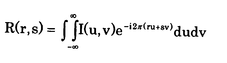 where, r and s are variables in the spatial-frequency domain.
OTF(u, v) = R(r, s)/|R(0, 0)|
Since the magnitude of the OTF is the MTF, the following
expression is satisfied.
MTF(r, s) = |OTF(u, v)|
The white-color MTF is calculated from the single-color
MTF, obtained as described above.
To obtain the white-color MTF, the MTF is weighted at
each wavelength and added. Since the above-described MTF has
a different value at each wavelength, the MTF can be expressed
in the following way when the MTF at a wavelength λ is
indicated by MTFλ.
MTF(r,s) = ∫ωλ MTFλ (r,s)dλ∫ωλ dλ
The MTF is highly weighted at visible-light wavelengths, and
the calculation is made.
More specifically, the MTF is obtained in the following
way when it is assumed, for example, that the three primary
colors (R, G, and B) are specified such that red light has a
wavelength of 656.27 nm with a weight of 1, green light has a
wavelength of 587.56 nm with a weight of 2, and blue light has
a wavelength of 486.13 nm with a weight of 1.
MTF(r, s) = (1 x MTF656.27 + 2 x MTF587.56 + 1 x MTF486.13 )/(1
+ 2 + 1)
Since the white-light MTF is measured only at one
wavelength (840 nm), calibration may be performed for other
wavelengths according to the result of measurement, as
compensation, to obtain the MTF at each wavelength. More
specifically, when the eye optical characteristic measuring
apparatus measures eye aberration, for example, at 840 nm,
color aberration WΔ(x, y) corresponding to a shift from the
wavefront aberrations W840(x, y) at a wavelength of 840 nm is
measured with the use of an eye model, W840(x, y) is added to
the color aberration WΔ(x, y), and the MTF is calculated at
each wavelength from this wavefront aberrations in the
following way.
Wλ (x, y) = W840 (x, y) + WΔ (x, y)
Fig. 16 is a flowchart of a correction-factor
determination method according to a second embodiment.
Processes at steps S101 to S105 are the same as in the first
embodiment. Then, the arithmetic part 210 calculates
correction data for the spherical power (5151). As a specific
process thereof, a process described in "4-1. Correction data
calculation (spherical power-1)" or "4-2. Correction data
calculation (spherical power-2)" can be used.
Next, the correction-factor setting part 213 of the
arithmetic part 210 subtracts a value (in this case, C/2)
corresponding to the astigmatic power C from the obtained
spherical power S to specify the initial value of the
spherical power S. This is performed because the fact that
the astigmatic power is obtained at a position where the back
focal line is almost on the retina is taken into account. The
value of C may be obtained from the refractive power or the
wavefront aberrations obtained in step S105, or appropriately
specified in advance. Then, the arithmetic part 210
calculates correction data for the astigmatic components
(S153). As a specific process thereof, a process described in
"4-3. Correction data calculation (astigmatism-1)", "4-4.
Correction data calculation (astigmatism-2)", or "4-5.
Correction data calculation (astigmatism-3)" can be used.
Then, in step S109, the arithmetic part 210 outputs data
in the same way as in the first embodiment.
Fig. 17 is a flowchart of a correction-factor
determination method according to a third embodiment.
Processes at steps S101 to S153 are the same as in the second embodiment. Then, thearithmetic part 210 finely adjusts the
spherical power (S161), and in step S109, the arithmetic part
210 outputs data in the same way as in the above-described
embodiment.
Processes at steps S101 to S153 are the same as in the second embodiment. Then, the
Fig. 18 shows a flowchart of spherical-power fine
adjustment.
In step S451, as described above, the arithmetic part 210
specifies a spherical power Ss used in simulation according to
the calculated S, C, and A. Then, the arithmetic part 210
slightly changes the correction value of Ss (for example, Ss -
0.25D, Ss + 0.25D) (S601). In this case, slightly changed Ss
should fall in Ss ± nΔS, a range of change specified in
advance. For example, when ΔS = 0.2 and "n" = 0, 1, 2, and 3,
changed values would be Ss - 0.6, Ss - 0.4, Ss - 0.2, Ss, Ss +
0.2, Ss + 0.4, and Ss + 0.6.
In steps S405 to S413, the arithmetic part 210 performs
processes such as Landolt's-ring retina image simulation and
Landolt's-ring template matching (S407) as described in the
above-mentioned embodiments.
When the determination part 212 determines no in step S411 or step S413, thearithmetic part 210 determines that the
Landolt's ring cannot be detected (S419). The arithmetic part
210 stores the direction and the fact that the Landolt's ring
cannot be detected in the direction, in the memory 240.
When the determination part 212 determines no in step S411 or step S413, the
Steps S421, S455, and S457 are the same as those
described above.
When the determination part 212 determines in step S455
that detection could be made in the number of directions equal
to or more than a half of the specified number of directions,
it is determined whether to finish fine adjustment (S603). If
no, the processing proceeds to step S601, the correction value
of the spherical power Ss is slightly changed, and the
processes of step S453 and subsequent steps are repeated. In
the process of step S503, the highest visual acuity Vs, the
number of directions where detection could be made, nh at the
directions where detection could be made are stored in the
memory 240 for each Ss, which has been slightly changed.
If yes in step S603, the arithmetic part 210 stores data
in the memory 240 (S595). The arithmetic part 210 stores the
results (for example, if the visual acuity is improved when S
is increased, then the increased S or if the visual acuity is
not changed when S is reduced, then the reduced S), obtained
by the fine adjustment performed in step S601. The arithmetic
part 210 can, for example, pick up spherical powers
corresponding to a specified visual acuity or higher from the
memory 240, and store in the memory 240 the weakest spherical
power corresponding to a specified visual acuity as a value
obtained by finely adjusting picked-up data.
A correction-data measuring method or a correction-data
measuring apparatus and system according to the present
invention can be provided by a correction-data measuring
program for making a computer execute the procedure of the
method or the apparatus and system, a computer-readable
recording medium having stored thereon the correction-data
measuring program, a program product which includes the
correction-data measuring program and can be loaded to an
internal memory of a computer, a computer such as a server
which includes the program, and others.
Measurement data which indicates the wavefront
aberrations of the eye under measurement is obtained by the
optical system 100 shown in Fig. 1. The apparatus therefor is
not limited to this. An Aberrometer and others can be used.
According to the present invention, a human observer
model, for example, is evaluated from a measurement result
obtained by an eye-characteristics measuring apparatus capable
of measuring even higher-order aberrations, not only when
higher-order aberrations, which correspond to a complete
objective correction, are used but also when lower-order
aberrations are added, a lower-order aberration amount which,
for example, improves how an image is seen is calculated, and
the data of correction factors such as S, C, and A is obtained
at that time to allow a result close to a subjective value to
be obtained.
Claims (27)
- A correction-factor determination apparatus comprising:wherein the correction-factor setting section specifies the correction factor according to a result obtained by the determination section, and the correction-factor setting section changes the correction factor by the correction-factor setting section until the determination section determines that the correction factor is appropriate.an image-data generation section for performing simulation of how an eyesight-test-chart target is seen, according to measurement data which indicates at least the wavefront aberrations of an eye under measurement, with a correction factor for correcting refraction being taken into account, to generate target retina image data;a correction-factor setting section for specifying a correction factor to be given to the image-data generation section; anda determination section for determining whether the specified correction factor is appropriate, according to corrected target retina image data generated by the image-data generation section and corrected by the correction factor specified by the correction-factor setting section,
- A correction-factor determination apparatus according to Claim 1, wherein the correction factor includes one of or a combination of plurality of a spherical power, an astigmatic power, and the angle of an astigmatic axis.
- A correction-factor determination apparatus according to Claim 2, whereinthe correction-factor setting section changes the correction factor in the order of the spherical power, the angle of the astigmatic axis, and the astigmatic power, andthe determination section determines whether the specified correction factor is appropriate in the order of the spherical power, the angle of the astigmatic axis, and the astigmatic power.
- A correction-factor determination apparatus according to Claim 2, wherein, when the spherical power and/or the astigmatic power is selected as the correction factor, the image-data generation section sequentially changes the eyesight-test-chart target with which the simulation is performed to eyesight-test-chart targets having different sizes, and performs the simulation of how the eyesight-test-chart target is seen to generate the target retina image data.
- A correction-factor determination apparatus according to Claim 2, wherein the eyesight-test-chart target with which the simulation is performed by the image-data generation section is a Landolt's ring target when it is determined whether the spherical power or the astigmatic power is appropriate.
- A correction-factor determination apparatus according to Claim 1, wherein the determination section determines whether the specified correction factor is appropriate, by comparing a correlation degree of predetermined eyesight-test-chart-target matching pattern data with the target retina image data obtained by the simulation.
- A correction-factor determination apparatus according to Claim 6, wherein the determination section performs determination with template matching by applying two-dimensional Fourier transform to the spatial frequency of a template and multiplying the resultant by the spatial frequency distribution of a retina image.
- A correction-factor determination apparatus according to Claim 6, wherein the image-data generation section calculates a pupil function from the wavefront aberrations, calculates the luminance distribution function of an eyesight target, multiplies the luminance distribution function by the spatial frequency distribution of an eye, and applies two-dimensional inverse Fourier transform to the resultant to obtain target retina image data simulated measurement data which indicates the refractive power distribution of the eye under measurement and/or target retina image data corrected by the specified correction factor.
- A correction-factor determination apparatus according to Claim 1, whereinthe image-data generation section generates MTF data as the simulation of how the eyesight-test-chart target is seen, with the measurement data which indicates at least the wavefront aberrations of the eye under measurement, and the correction factor for correcting refraction being taken into account, andthe determination section determines from the generated MTF data whether the correction factor is appropriate.
- A correction-factor determination apparatus according to Claim 1, wherein the correction-factor setting section performs correction from a weak correction point.
- A correction-factor determination apparatus according to Claim 1, wherein the correction-factor setting section performs correction according to a subjective measurement procedure.
- A correction-factor determination apparatus according to Claim 1, further comprising
a display section for displaying the result of determination made by the determination section and the target retina image data generated by the image-data generation section, or for displaying target retina image data obtained with an appropriate correction factor and a correction factor close thereto. - A correction-factor determination method including:wherein the correction factor is specified in the step of specifying the correction factor, according to a result obtained in the step of determining, and the correction factor is changed in the step of specifying the correction factor until it is determined that the correction factor is appropriate in the step of determining.a step of generating target retina image data by performing simulation of how an eyesight-test-chart target is seen, according to measurement data which indicates at least the wavefront aberrations of an eye under measurement, with a correction factor for correcting refraction being taken into account;a step of specifying a correction factor for generating the target retina image data; anda step of determining whether the specified correction factor is appropriate, according to corrected target retina image data generated in the step of generating the target retina image data and corrected by the correction factor specified in the step of specifying the correction factor,
- A correction-factor determination method according to Claim 13, wherein the correction factor includes one of or a combination of plurality of a spherical power, an astigmatic power, and the angle of an astigmatic axis.
- A correction-factor determination method according to Claim 14, whereinthe correction factor is changed in the order of the spherical power, the angle of the astigmatic axis, and the astigmatic power in the step of specifying the correction factor, andit is determined whether the correction factor is appropriate in the order of the spherical power, the angle of the astigmatic axis, and the astigmatic power in the step of determining.
- A correction-factor determination method according to Claim 14, wherein, when the spherical power and/or the astigmatic power is selected as the correction factor, the eyesight-test-chart target with which the simulation is performed is sequentially changed to eyesight-test-chart targets having different sizes, and performs the simulation of how the eyesight-test-chart target is seen to generate the target retina image data, in the step of generating the target retina image data.
- A correction-factor determination method according to Claim 14, wherein the eyesight-test-chart target with which the simulation is performed in the step of generating the target retina image data is a Landolt's ring target when it is determined whether the spherical power or the astigmatic power is appropriate.
- A correction-factor determination method according to Claim 13, wherein it is determined whether the specified correction factor is appropriate, by comparing a correlation degree of predetermined eyesight-test-chart-target matching pattern data with the target retina image data simulated, in the step of determining.
- A correction-factor determination method according to Claim 18, wherein determination is performed with template matching by applying two-dimensional Fourier transform to the spatial frequency of a template and multiplying the resultant by the spatial frequency distribution of a retina image, in the step of determining.
- A correction-factor determination method according to Claim 18, wherein a pupil function is calculated from the wavefront aberrations, the luminance distribution function of an eyesight target is calculated, the luminance distribution function is multiplied the resultant by the spatial frequency distribution of an eye, and two-dimensional inverse Fourier transform is applied to the resultant to obtain target retina image data obtained by simulating measurement data which indicates the refractive power distribution of the eye under measurement and/or target retina image data corrected by the specified correction factor, in the step of generating the target retina image data.
- A correction-factor determination method according to Claim 13, whereinMTF data is generated as the simulation of how the eyesight-test-chart target is seen, with the measurement data which indicates at least the wavefront aberrations of the eye under measurement, and the correction factor for correcting refraction being taken into account, in the step of generating the target retina image data, andit is determined from the generated MTF data whether the correction factor is appropriate, in the step of determining.
- A correction-factor determination method according to Claim 13, wherein correction is performed from a weak correction point in the step of specifying the correction factor.
- A correction-factor determination method according to Claim 13, wherein correction is performed according to a subjective measurement procedure in the step of specifying the correction factor.
- A correction-factor determination method according to Claim 13, further including a step of precisely measuring an astigmatic power and the angle of an astigmatic axis.
- A correction-factor determination method according to Claim 13, further including a spherical-power fine-adjustment step of finely adjusting an obtained spherical power to obtain a spherical power which causes to obtain a further high visual acuity value.
- A correction-factor determination method including:a step of calculating which uses a first spherical power included in measurement data which indicates the refractive-power distribution of an eye under measurement, as a correction factor to calculate a second spherical power by the correction-factor determination method described in Claim 12;a step of obtaining the second spherical power from the second spherical power by compensating a value based on a first astigmatic power included in the measurement data which indicates the refractive-power distribution of the eye under measurement; anda step of calculating which uses the second spherical power as a correction factor to calculate a second astigmatic power by the correction-factor determination method described in Claim 13.
- A correction-factor determination method according to one of Claims 13 to 26, wherein the wavefront aberrations comprise higher-order aberration.
Applications Claiming Priority (3)
| Application Number | Priority Date | Filing Date | Title |
|---|---|---|---|
| JP2002268033A JP4185337B2 (en) | 2002-09-13 | 2002-09-13 | Correction element determination apparatus and method |
| JP2002268033 | 2002-09-13 | ||
| PCT/JP2003/011583 WO2004023990A1 (en) | 2002-09-13 | 2003-09-10 | Correction factor judging device and method |
Publications (2)
| Publication Number | Publication Date |
|---|---|
| EP1541081A1 true EP1541081A1 (en) | 2005-06-15 |
| EP1541081A4 EP1541081A4 (en) | 2008-12-31 |
Family
ID=31986738
Family Applications (1)
| Application Number | Title | Priority Date | Filing Date |
|---|---|---|---|
| EP03795375A Withdrawn EP1541081A4 (en) | 2002-09-13 | 2003-09-10 | DEVICE AND METHOD FOR DETERMINING A CORRECTION FACTOR |
Country Status (5)
| Country | Link |
|---|---|
| US (1) | US7246906B2 (en) |
| EP (1) | EP1541081A4 (en) |
| JP (1) | JP4185337B2 (en) |
| AU (1) | AU2003264405A1 (en) |
| WO (1) | WO2004023990A1 (en) |
Cited By (1)
| Publication number | Priority date | Publication date | Assignee | Title |
|---|---|---|---|---|
| GB2427684A (en) * | 2003-02-03 | 2007-01-03 | Topcon Corp | Opthalmic data processing |
Families Citing this family (17)
| Publication number | Priority date | Publication date | Assignee | Title |
|---|---|---|---|---|
| GB0303193D0 (en) * | 2003-02-12 | 2003-03-19 | Guillon Michael | Methods & lens |
| US7175278B2 (en) * | 2003-06-20 | 2007-02-13 | Visx, Inc. | Wavefront reconstruction using fourier transformation and direct integration |
| CA2555705C (en) * | 2004-02-20 | 2015-04-07 | Visx, Incorporated | Volumetric point spread function for eye diagnosis and treatment |
| JP4528049B2 (en) * | 2004-07-29 | 2010-08-18 | 株式会社トプコン | Ophthalmic equipment |
| JP4649168B2 (en) * | 2004-10-22 | 2011-03-09 | 株式会社トプコン | Eye high-order aberration measurement system |
| US7726811B2 (en) | 2006-02-14 | 2010-06-01 | Lai Shui T | Subjective wavefront refraction using continuously adjustable wave plates of Zernike function |
| US7699471B2 (en) * | 2006-02-14 | 2010-04-20 | Lai Shui T | Subjective refraction method and device for correcting low and higher order aberrations |
| WO2008014330A2 (en) * | 2006-07-25 | 2008-01-31 | Lai Shui T | Method of making high precision optics having a wavefront profile |
| US20130169928A1 (en) | 2011-12-29 | 2013-07-04 | Elwha LLC, a limited liability company of the State of Delaware | Fabrication technique for replaceable optical corrective elements |
| US9033497B2 (en) | 2011-12-29 | 2015-05-19 | Elwha Llc | Optical device with interchangeable corrective elements |
| US9052502B2 (en) | 2011-12-29 | 2015-06-09 | Elwha Llc | Corrective alignment optics for optical device |
| TWI588560B (en) | 2012-04-05 | 2017-06-21 | 布萊恩荷登視覺協會 | Lens, device, method and system for refractive error |
| US9498115B2 (en) | 2012-04-06 | 2016-11-22 | Nidek Co., Ltd. | Ophthalmic measurement device, and ophthalmic measurement system equipped with ophthalmic measurement device |
| US9201250B2 (en) | 2012-10-17 | 2015-12-01 | Brien Holden Vision Institute | Lenses, devices, methods and systems for refractive error |
| EP2908773B1 (en) | 2012-10-17 | 2024-01-03 | Brien Holden Vision Institute | Lenses, devices, methods and systems for refractive error |
| JP6693240B2 (en) * | 2016-03-31 | 2020-05-13 | 株式会社ニデック | Eyeglass prescription auxiliary device |
| EP3295864B1 (en) * | 2016-09-15 | 2019-05-15 | Carl Zeiss Vision International GmbH | Apparatus for assisting in establishing a correction for correcting heterotropia or heterophoria and method of operating a computer for assisting in establishing a correction for correcting heterotropia or heterophoria |
Family Cites Families (16)
| Publication number | Priority date | Publication date | Assignee | Title |
|---|---|---|---|---|
| GB904571A (en) * | 1960-07-27 | 1962-08-29 | Deryck Humphriss | Improvements in or relating to sight-testing equipment |
| DE2901459C2 (en) * | 1979-01-16 | 1984-07-12 | J.D. Möller Optische Werke GmbH, 2000 Wedel | Phoropters |
| JPS59183726A (en) | 1983-04-01 | 1984-10-18 | 株式会社トプコン | Refractive force measuring apparatus |
| JP3347507B2 (en) * | 1995-02-15 | 2002-11-20 | ホーヤ株式会社 | Eye optical system simulation device |
| JP3599530B2 (en) * | 1997-06-30 | 2004-12-08 | 株式会社ニデック | Optometry device |
| JP2001095760A (en) * | 1999-09-28 | 2001-04-10 | Topcon Corp | Eye optical characteristics measurement device |
| US6338559B1 (en) * | 2000-04-28 | 2002-01-15 | University Of Rochester | Apparatus and method for improving vision and retinal imaging |
| US6460997B1 (en) * | 2000-05-08 | 2002-10-08 | Alcon Universal Ltd. | Apparatus and method for objective measurements of optical systems using wavefront analysis |
| JP3825654B2 (en) * | 2000-05-22 | 2006-09-27 | Hoya株式会社 | Ophthalmic optical system simulation method and apparatus |
| EP1158338B1 (en) * | 2000-05-22 | 2006-03-01 | Hoya Corporation | Method for simulating an ocular optical system and apparatus therefor |
| MXPA03003126A (en) * | 2000-10-10 | 2004-07-30 | Univ Rochester | Determination of ocular refraction from wavefront aberration data. |
| JP4649035B2 (en) | 2000-10-18 | 2011-03-09 | 株式会社トプコン | Eye characteristics measuring device |
| JP2002209854A (en) | 2000-10-18 | 2002-07-30 | Topcon Corp | Optical property measuring device |
| WO2002034126A1 (en) * | 2000-10-20 | 2002-05-02 | Wavefront Sciences, Inc. | Method for computing visual performance from objective ocular aberration measurements |
| JP4663148B2 (en) | 2001-02-09 | 2011-03-30 | 株式会社トプコン | Eye characteristics measuring device |
| JP4663147B2 (en) | 2001-02-09 | 2011-03-30 | 株式会社トプコン | Eye characteristics measuring device |
-
2002
- 2002-09-13 JP JP2002268033A patent/JP4185337B2/en not_active Expired - Lifetime
-
2003
- 2003-09-10 WO PCT/JP2003/011583 patent/WO2004023990A1/en not_active Ceased
- 2003-09-10 US US10/527,447 patent/US7246906B2/en not_active Expired - Fee Related
- 2003-09-10 EP EP03795375A patent/EP1541081A4/en not_active Withdrawn
- 2003-09-10 AU AU2003264405A patent/AU2003264405A1/en not_active Abandoned
Cited By (1)
| Publication number | Priority date | Publication date | Assignee | Title |
|---|---|---|---|---|
| GB2427684A (en) * | 2003-02-03 | 2007-01-03 | Topcon Corp | Opthalmic data processing |
Also Published As
| Publication number | Publication date |
|---|---|
| JP4185337B2 (en) | 2008-11-26 |
| US20050270490A1 (en) | 2005-12-08 |
| WO2004023990A1 (en) | 2004-03-25 |
| EP1541081A4 (en) | 2008-12-31 |
| AU2003264405A1 (en) | 2004-04-30 |
| US7246906B2 (en) | 2007-07-24 |
| JP2004105236A (en) | 2004-04-08 |
Similar Documents
| Publication | Publication Date | Title |
|---|---|---|
| CA2514807C (en) | Ophthalmic data measuring apparatus, ophthalmic data measurement program and eye characteristic measuring apparatus | |
| US7360894B2 (en) | Opthalmological apparatus | |
| US7246906B2 (en) | Correction-factor determination apparatus and method | |
| US7677731B2 (en) | Eye optical characteristic measuring apparatus | |
| US7270415B2 (en) | Retina observation apparatus and retina observation method | |
| US7216980B2 (en) | Eye characteristic measuring apparatus | |
| EP1334691A1 (en) | Optical characteristics measuring device | |
| JP4318463B2 (en) | Correction data measurement device, correction data measurement program, recording medium recording correction data measurement program, and eye characteristic measurement device | |
| JP4471680B2 (en) | Ophthalmic equipment | |
| JP4528049B2 (en) | Ophthalmic equipment | |
| CN118591336B (en) | Methods, apparatus, and computer programs for determining the sensitivity of at least one eye of a test subject. | |
| JP4649168B2 (en) | Eye high-order aberration measurement system | |
| JP4185331B2 (en) | Correction data measuring method, measuring apparatus, measuring program, and recording medium recording the measuring program | |
| JP2004337236A (en) | Ophthalmic data measuring device, ophthalmic data measuring program, recording medium storing ophthalmic data measuring program | |
| CN120282744A (en) | Method for determining visual acuity characteristics of a test object, use of an adapted optotype and device | |
| JP2001120504A (en) | Ophthalmic equipment | |
| Xu et al. | Information fusion method for ocular aberrations measurement based on subjective visual compensation | |
| Radhakrishnan et al. | Optical, perceptual and adaptational implications of different presbyopic corrections |
Legal Events
| Date | Code | Title | Description |
|---|---|---|---|
| PUAI | Public reference made under article 153(3) epc to a published international application that has entered the european phase |
Free format text: ORIGINAL CODE: 0009012 |
|
| 17P | Request for examination filed |
Effective date: 20050317 |
|
| AK | Designated contracting states |
Kind code of ref document: A1 Designated state(s): AT BE BG CH CY CZ DE DK EE ES FI FR GB GR HU IE IT LI LU MC NL PT RO SE SI SK TR |
|
| AX | Request for extension of the european patent |
Extension state: AL LT LV MK |
|
| DAX | Request for extension of the european patent (deleted) | ||
| A4 | Supplementary search report drawn up and despatched |
Effective date: 20081127 |
|
| 17Q | First examination report despatched |
Effective date: 20090325 |
|
| STAA | Information on the status of an ep patent application or granted ep patent |
Free format text: STATUS: THE APPLICATION IS DEEMED TO BE WITHDRAWN |
|
| 18D | Application deemed to be withdrawn |
Effective date: 20091006 |