EP1541050A1 - Button - Google Patents
Button Download PDFInfo
- Publication number
- EP1541050A1 EP1541050A1 EP03766652A EP03766652A EP1541050A1 EP 1541050 A1 EP1541050 A1 EP 1541050A1 EP 03766652 A EP03766652 A EP 03766652A EP 03766652 A EP03766652 A EP 03766652A EP 1541050 A1 EP1541050 A1 EP 1541050A1
- Authority
- EP
- European Patent Office
- Prior art keywords
- shaft
- button
- opening
- fixture
- neck
- Prior art date
- Legal status (The legal status is an assumption and is not a legal conclusion. Google has not performed a legal analysis and makes no representation as to the accuracy of the status listed.)
- Granted
Links
Images




Classifications
-
- A—HUMAN NECESSITIES
- A44—HABERDASHERY; JEWELLERY
- A44B—BUTTONS, PINS, BUCKLES, SLIDE FASTENERS, OR THE LIKE
- A44B1/00—Buttons
- A44B1/18—Buttons adapted for special ways of fastening
- A44B1/28—Buttons adapted for special ways of fastening with shank and counterpiece
- A44B1/34—Buttons adapted for special ways of fastening with shank and counterpiece with snap-action counterpiece
-
- A—HUMAN NECESSITIES
- A44—HABERDASHERY; JEWELLERY
- A44B—BUTTONS, PINS, BUCKLES, SLIDE FASTENERS, OR THE LIKE
- A44B1/00—Buttons
- A44B1/08—Constructional characteristics
-
- Y—GENERAL TAGGING OF NEW TECHNOLOGICAL DEVELOPMENTS; GENERAL TAGGING OF CROSS-SECTIONAL TECHNOLOGIES SPANNING OVER SEVERAL SECTIONS OF THE IPC; TECHNICAL SUBJECTS COVERED BY FORMER USPC CROSS-REFERENCE ART COLLECTIONS [XRACs] AND DIGESTS
- Y10—TECHNICAL SUBJECTS COVERED BY FORMER USPC
- Y10T—TECHNICAL SUBJECTS COVERED BY FORMER US CLASSIFICATION
- Y10T24/00—Buckles, buttons, clasps, etc.
- Y10T24/36—Button with fastener
- Y10T24/367—Covers
- Y10T24/3672—Metal or plastic caps
-
- Y—GENERAL TAGGING OF NEW TECHNOLOGICAL DEVELOPMENTS; GENERAL TAGGING OF CROSS-SECTIONAL TECHNOLOGIES SPANNING OVER SEVERAL SECTIONS OF THE IPC; TECHNICAL SUBJECTS COVERED BY FORMER USPC CROSS-REFERENCE ART COLLECTIONS [XRACs] AND DIGESTS
- Y10—TECHNICAL SUBJECTS COVERED BY FORMER USPC
- Y10T—TECHNICAL SUBJECTS COVERED BY FORMER US CLASSIFICATION
- Y10T24/00—Buckles, buttons, clasps, etc.
- Y10T24/36—Button with fastener
- Y10T24/3683—Button with cavity for friction grip fastener
-
- Y—GENERAL TAGGING OF NEW TECHNOLOGICAL DEVELOPMENTS; GENERAL TAGGING OF CROSS-SECTIONAL TECHNOLOGIES SPANNING OVER SEVERAL SECTIONS OF THE IPC; TECHNICAL SUBJECTS COVERED BY FORMER USPC CROSS-REFERENCE ART COLLECTIONS [XRACs] AND DIGESTS
- Y10—TECHNICAL SUBJECTS COVERED BY FORMER USPC
- Y10T—TECHNICAL SUBJECTS COVERED BY FORMER US CLASSIFICATION
- Y10T24/00—Buckles, buttons, clasps, etc.
- Y10T24/45—Separable-fastener or required component thereof [e.g., projection and cavity to complete interlock]
- Y10T24/45225—Separable-fastener or required component thereof [e.g., projection and cavity to complete interlock] including member having distinct formations and mating member selectively interlocking therewith
- Y10T24/4588—Means for mounting projection or cavity portion
- Y10T24/45906—Means for mounting projection or cavity portion having component of means permanently deformed during mounting operation
- Y10T24/45927—Means for mounting projection or cavity portion having component of means permanently deformed during mounting operation and inserted into or through cavity or projection
Definitions
- the present invention relates to a button used, for instance, in jeans. More specifically this invention relates to a button including a button body and a fixture for holding fabric such as a garment from the opposite side to the button body for fixing the button body to the fabric.
- buttons used for a garment such as jeans
- a button including a button body and a fixture for holding fabric such as a garment from the opposite side to the button body for fixing the button body to the fabric.
- USP 5575043 discloses a button for jeans.
- This button includes a button body having a button covering member and an accommodation member incorporated inside this button covering member and a fixture for holding fabric such as a garment from the opposite side to the button body for fixing the button body to the fabric.
- the button covering member includes a front side covering material formed by spinning metal and a back side covering member also formed by spinning metal.
- the back side covering member includes a cylindrical neck, a flange formed at an edge of the neck and having an outer diameter larger than that of the neck, and an opening formed at another edge of the neck.
- An outer periphery of the front side covering member is engaged with an outer periphery of the flange to form a button having a disk-like form.
- the accommodation member is made of synthetic resin and includes a collar accommodated in the button and a shaft accommodated in the neck. Another end of the shaft protrudes from the opening, and an insert hole for a fixture to be inserted therein is formed at a center of the protruding end face.
- the accommodation member and the button covering member are not sufficiently integrated with each other.
- a form of a tip of the shaft namely a form of a cross section near the protruding end part protruding from the opening is formed by beveling corners of the square with R-curved surfaces, and even when the fixture is inserted into the insert hole of the accommodation member, an outer periphery of the shaft only contacts the inner periphery of the opening, and sometimes the button covering member may rotate relative to the accommodation member.
- some decorations such as a character or a logo are provided on a surface of a button used in jeans or the like, namely on a front side covering material of the button covering member, and when the phenomenon as described above occurs, the character or the like becomes harder to be recognized with the beauty lost, which is not preferable from the designing point of view.
- an object of the present invention is to provide a button capable of ensuring tight integration of a shell member constituting a covering shell of a button and an accommodation member incorporated in the shell member for preventing relative rotation of the two members without fail.
- the button according to the present invention includes a button body and a fixture for fixing the button body to a fabric from the opposite side to the button body with the fabric therebetween, in which: the button body has a shell member constituting an outer shell for the button and an accommodation member accommodated in the shell member; the shell member includes a button top covering part and a cylindrical neck provided on the back side of the button cover and having an opening at an outer edge thereof; the accommodation member includes a shaft accommodated in the neck with a part thereof protruding from the opening and an insert hole formed on the protruding end face of the shaft for the fixture to be inserted therein and is formed with a material softer at least as compared to that used for forming the neck with the outer periphery thereof capable of expanding outward from the inner periphery of the opening when the fixture is inserted into the insert hole; and crimping parts formed on one of the inner periphery of the opening or the outer peripheral surface of the shaft with a prespecified space in the circumferential direction thereof so as to cri
- the expression that the crimping parts are formed with a prespecified space in the circumferential direction as used herein includes the case in which a plurality of crimping or fetched parts are provided in the circumferential direction each with a step in the axial direction of the shaft.
- the shell member and the accommodation member can be integrated with each other by the crimping parts. In other words, relative rotation of the shell member against the accommodation member can be prevented without fail.
- the crimping parts are formed with a prespecified space therebetween in the circumferential direction, the crimping parts uniformly crimp into the entire periphery of the shaft, so that the shell member and the accommodation member can be integrated with each other more tightly (uniform crimping effect).
- the crimping parts are preferably a plurality of protrusions formed with a prespecified space along an internal periphery of the opening.
- the shaft preferably has a round cross section substantially perpendicular to the center line thereof.
- the protrusions formed on the inner periphery of the opening crimp into an outer peripheral surface of the shaft, so that the shell member and the accommodation member are tightly integrated with each other.
- the protrusions are formed along the inner periphery of the opening, when the opening is formed by punching in the press machining or the like, also the protrusions can be formed simultaneously. Therefore, the button according to the present invention can be manufactured with low cost and without increase of machining steps (simultaneously machining effect).
- the protrusion preferably has a form with the width gradually becoming smaller from the inner periphery of the opening toward the center of the opening part.
- the form with the width gradually becoming smaller from the inner periphery of the opening toward the center of the opening includes, for instance, a tooth-like form, a triangular form, a trapezoidal form, a circular form and the like.
- the protrusions have a form with the width gradually becoming smaller from the inner periphery of the opening toward the center of the opening, so that the protrusions easily crimp into an outer peripheral surface of the shaft.
- the opening has a polygonal form having 5 or more corners, preferably having 5 to 12 corners, and each side forming the polygon functions as the crimping section, and the shaft preferable has a round cross section substantially perpendicular to the axial line of the shaft.
- each side of the polygon of the opening functions as the crimping section and crimps into the outer peripheral surface of the shaft, so that the shell member and the accommodation member can be integrated with each other. Even with this configuration, the uniformly crimping effect and simultaneously machining effect can be expected.
- the opening has a circular form
- the shaft has a cross section substantially perpendicular to the center line thereof and having a polygonal form with 5 or more corner, preferably having 5 to 12 corners, and each side forming the polygon preferably functions as the crimping section.
- the inner periphery of the opening crimps into each corner of the polygonal cross section of the shaft, so that the shell part and the accommodation member can be integrated with each other.
- the uniformly crimping effect can be expected.
- the shaft is integrally molded, for instance, by molding resin, it is possible to mold a section near the protruding edge of the shaft so that a cross section thereof is polygonal, so that also the simultaneously machining effect can be expected.
- the insert hole preferably has steps with the inner diameter thereof becoming smaller step by step from an end face opposite to the protruding end face of the shaft toward the protruding end face.
- the shaft of the accommodation member can be expanded largely in association with insertion of the fixture (into the insert hole of the accommodation member). Therefore also the crimping length becomes larger, so that the more secure integration can be expected.
- the shaft has an accommodation portion having the substantially same diameter as the inner diameter of the neck, a protruding portion protruding from the opening and crimping into the opening, and an intermediate portion coupling the accommodation portion to the protruding portion, and preferably a clearance is provided between the intermediate portion and the neck.
- a plurality of projected treads radially extending from the insert hole as the center are preferably provided on a protruding end face of the shaft with a prespecified angular space
- the fixture has an insert shaft inserted into an insert hole of the accommodation member and a flange integrally formed on and with a base end of this insert shaft, and also protrusions facing the projected treads with fabric therebetween against are preferably formed on the inner surface of the flange in the circumferential direction around the insert hole.
- buttons having the ordinary structure when a force is loaded to the button body in the rotating direction, sometimes the button body and the fixture may integrally rotate against fabric.
- the shell member constituting the button body is preferably made of metal and the accommodation member is preferably formed from synthetic resin.
- the shell member constituting the button body can easily be manufactured by press machining of metal and also the accommodation member by molding synthetic resin, which ensures low cost production of the button.
- Fig. 1 is a cross-sectional view showing a case in which a button according to the present invention is applied to that for jeans, and the view shows the state in which the button is fixed on fabric
- Fig. 2 is a cross-sectional view showing each component in the state where the button for jeans according to the embodiment above has been removed from the fabric.
- a button 1 for jeans includes a button body 10, and a fixture 40 for fixing the button body 10 to a fabric 2 from the opposite side to the button body 10 with the fabric of a garment therebetween.
- the button body 10 includes a shell member 11 constituting an outer shell of the button and an accommodation member 31 accommodated in the shell member 11.
- the shell member 11 includes, as shown in Fig. 3, a button covering material 12 formed by spinning metal and constituting a button cover 22, and a button base material 13 also formed by spinning metal.
- the button base material 13 includes a neck 14 having a cylindrical form, a circular flange 15 integrally formed with the neck 14, bending from an end (upper edge in Fig. 1 and Fig. 2) of the neck 14 at right corners outward, and having a larger outer form (outer diameter) than an outer form (an outer diameter) of the neck 14, a an upright upper rim 16 integrally formed with an outer periphery of the flange 15 and bend at right corners to the opposite side from the neck 14, and an opening 17 formed on the other end of the neck 14.
- Crimping parts 18 crimping in the accommodation member 31 are provided with a space therebetween at a prespecified position along the circumferential direction on the inner periphery of the opening 17.
- the crimping parts 18 are a plurality of convex parts 19 formed with a prespecified space therebetween at a prespecified position along the inner periphery of the opening 17.
- Each of the convex parts 19 has a form with the width becoming gradually smaller from the inner periphery of the opening 17 toward a center of the opening 17, herein forming like gear teeth.
- the button covering material 12 has a disk-like form and an outer periphery 12A thereof is engaged in and fixed to an outer periphery of the flange 15 from the outside.
- a space 21 is formed between the button covering material 12 and the flange 15.
- the accommodation member 31 includes, as shown in Fig. 3, a collar 32 accommodated within the space 21 between the button covering material 12 and the flange 15, a shaft 33 accommodated in the neck 14 and having a round cross section perpendicular to the center line thereof, and an insert hole 34 formed on an end face protruding from the neck 14 of the shaft 33 for the fixture 40 to be inserted therein.
- the accommodation 31 is made of a material softer at least than that used for forming the neck 14 and also allowing to expand the external form of the shaft 33 to the outer position from the inner contour of the opening 17 when the fixture 40 is inserted into the insert hole 34 such as synthetic resin as used in this embodiment.
- the collar 32 has a form like a disk with the outer diameter reaching the first circular rib 15A of the flange 15 and the width substantially equal to the space 21 between the button covering material 12 and the flange 15.
- the shaft 33 has the accommodation portion 33A having the substantially same outer diameter as the inner diameter of the neck 14 of the shell member 11, a protruding portion 33C having the outer diameter smaller than the inner diameter of the opening 17 and protruding from the opening 17, and the intermediate portion 33B having the outer diameter smaller than an outer diameter of the accommodation portion 33A and larger than an outer diameter of the protruding portion 33C and coupling the accommodation portion 33A to the protruding portion 33C.
- An outer diameter of the intermediate portion 33B is smaller than an inner diameter of the neck 14 so that a clearance 35 is formed between the intermediate portion 33B and the neck 14.
- a plurality of (four) projected treads 36 are formed on a protruding end face of the protruding portion 33C, namely on a protruding end face of the shaft 33 with a prespecified space therebetween (at an angular space of 90 degrees) each extending radially from the insert hole 34 as a center.
- the insert hole 34 has a step-like form with the inner diameter becoming smaller step by step from an end face opposite to the protruding end face of the shaft 33 toward the protruding end face.
- the insert hole 34 including a first hole 34A, a second hole 34B with the inner diameter smaller than the first hole 34A, and a third hole 34C with the inner diameter smaller than that of the second hole 34B are arranged sequentially on the three steps as described above.
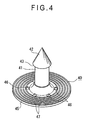
- the fixture 40 includes, as shown in Fig. 4, an insert shaft 41 to be inserted into the insert hole 34 of the accommodation member 31, and a flange 45 integrally formed on a base end side of the insert shaft 41.
- the fixture 40 is made of metal.
- the insert shaft 41 includes a guide part 42 having a conical tip and also having a round cross section perpendicular to the center line of the insert shaft 41 and an engagement 43.
- the insert shaft 41 has the outer diameter larger than an inner diameter of the second hole 34B of the insert hole 34, and because of the difference, the shaft 33 can expand to the outer side to crimp into the crimping part 18. For instance, when an inner diameter of the second hole 34B is 15 mm and an outer diameter of the insert shaft 41 is 21 mm, the inner diameter of the hole 34B expands by the difference, namely by 6 mm, and the shaft 33 can crimp into the crimping part 18.
- protrusions 46 each having a form like a quadrangular pyramid, opposing to the projected treads 36 of the accommodation member 31 with the fabric 2 therebetween, and provided in the circumferential direction of the flange 45 are and also ring-formed concavo-convex portions 47 provided concentrically around the insert shaft 41.
- the convex parts 19 are formed on the inner periphery of the opening 17 with a prespecified space at specified positions in the circumferential direction, and the convex parts 19 crimp into the shaft 33 of the accommodation member 31, namely into the protruding portions 33C, so that the shell member 11 and the accommodation member 31 are integrated with each other. In other words, relative rotation between the shell member 11 and the accommodation member 31 can be prevented without fail.
- the fabric 2 is held between the protruding end face of the shaft 33 of the accommodation member 31 and the inner surface of the flange 45 of the fixture 40.
- the plurality of projected treads 36 are radially provided on the protruding end face of the shaft 33 and further protrusions 46 facing against the projected treads 36 with the fabric 2 therebetween on the inner surface of the flange 45 of the fixture 40, namely as the projected treads 36 and the protrusions 46 function each as a rotation stop, so that relative rotation of the button body 10 and the fixture 40 against the fabric 2 can be prevented without fail.
- the present invention is not limited to a structure of a button for jeans described in the embodiment above, and also includes the modifications as described below.
- the so-called gear-teeth type of convex parts 19 are formed at specified positions with a prespecified space along the inner periphery of the opening 17, but a form of the convex parts 19 is not limited to the form like gear-teeth, and any of a triangular form, a trapezoidal form, a circular form and the like may be employed, or it does not even have to be protruded. In brief, any form allowing crimping into the accommodation member 31 may be employed.
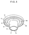
- the opening 17 may have a polygonal form such as an octagonal one as shown in Fig. 5, and each of the sides of this polygon may be used as the crimping part 18.
- a number of corners in the polygon is five or more, and preferably in the range from 5 to 12.
- the shaft 33 protruding portion 33C
- each side of the polygon of the opening 17 functions (works) as the crimping part 18 and crimps into an outer peripheral surface of the shaft 33 (protruding portion 33C), so that the shell member 11 and accommodation member 31 can be integrated with each other.
- the uniform crimping effect and simultaneously machining effect as described in (2) can be expected.
- the same effects can be achieved.
- Fig. 6 shows a case in which the opening 17 has a round form
- Fig. 7 shows a case in which a cross section of the shaft 33 (protruding portion 33C) is hexagonal
- Fig. 8 shows a case in which a cross section of the shaft 33 (protruding portion 33C) is octagonal.
- each corner of the polygon as a cross section of the shaft 33 can function as the crimping part 18.
- the inner periphery of the opening 17 crimp into corners of the polygonal cross section of the shaft 33 (protruding portion 33C), so that the shell member 11 and the accommodation member 31 can be integrated with each other.
- the uniformly crimping effect can be expected, and in addition, when the shaft 33 is molded integrally, for instance, by molding synthetic resin, a portion near the protruding edge of the shaft 33 can be formed with a polygonal cross section, so that also the simultaneously machining effect can be expected.
- the button body 10 includes the metal-made shell member 11 and the accommodation member 31 made of synthetic resin, but any other material may be used for the accommodation member 31 on the condition that the material is softer than that used for forming the neck 14 of the shell member 11 and allows outward expansion of an external form of the shaft 33 to the outer position from the inner contour of the opening 17 when the fixture 40 is inserted into the insert hole 34.
- the material for the fixture 40 is not limited to metal, and any other material such as, for instance, synthetic resin may be used on the condition that the material allows outward expansion of the shaft 33 of the accommodation member 31 when the fixture 40 is inserted into the insert hole 34 of the accommodation member 31.
- the shell member 11 includes the button covering material 12 and button base material 13, but these components may be configured integrally.
- the insert hole 34 is formed at the center of the accommodation member 31 and this insert hole 34 has three steps, but the number of steps may be two or four or more, and also the insert hole 34 may be a straight hole.
- the conical guide part 42 for guiding insertion and the engagement 43 are formed at a tip of the insert shaft 41 of the fixture 40, but the guide part 42 for guiding insertion and the engagement 43 may be provided as several steps along the axial direction of the insert shaft 41.
- a plurality of projected treads 44 are provided on the outer peripheral surface of the insert shaft 41 with a specified space therebetween along the axial direction. With the configuration, the projected treads 44 crimp into the insert hole 34 of the accommodation member 31, so that the function for stopping rotation of the accommodation member 31 and the fixture 40 can further be improved.
- buttons for jeans are described, but the button according to the present invention is not limited to that for jeans, and can be used for other types of garments or for other than garments.
- the present invention is applicable to buttons used for garments such as jeans and for other applications.
Landscapes
- Slide Fasteners, Snap Fasteners, And Hook Fasteners (AREA)
- Details Of Garments (AREA)
- Mechanical Control Devices (AREA)
Abstract
Description
Claims (10)
- A button comprising: a button body (10); and a fixture (40) for fixing the button body (10) to a fabric (2) from the opposite side to the button body with the fabric there between,
wherein the button body (10) comprises a shell member (11) constituting an outer shell of the button and an accommodation member (31) stored in the shell member,
the shell member (11) includes a button cover (22) and a neck (14) cylindrically formed on a back side of the button cover and having an opening (17) at an outer edge thereof,
the accommodation member (31) includes a shaft (33) accommodated in the neck (14) with a portion thereof protruding from the opening (17) and an insert hole (34) formed on a protruding end face of this shaft for the fixture (40) to be inserted therein, the accommodation member being made of a material softer at least than that used for forming the neck and allowing for outer expansion of an external form of the shaft to a position outer from the inner contour of the opening when the fixture is inserted into the insert hole, and
crimping parts (18) are formed on one of an inner periphery of the opening (17) or an outer peripheral surface of the shaft (33) at specified positions with a prespecified space therebetween in the circumferential direction so as to crimp into or crimped by the other. - The button according to claim 1,
wherein the crimping parts (18) are a plurality of convex parts (19) formed at prespecified positions with a prespecified space therebetween along the inner periphery of the opening (17). - The button according to claim 2,
wherein the shaft (33) has a round cross section substantially perpendicular to the center line of the shaft. - The button according to claim 2 or claim 3,
wherein the convex parts (19) each has a form with the width gradually becoming smaller from the inner periphery of the opening (17) toward the center of the opening. - The button according to claim 1,
wherein the opening (17) has a polygonal form with 5 or more corners and each of the sides forming this polygon functions as the crimping parts (18), and
the shaft (33) has a round cross section substantially perpendicular to the center line of the shaft. - The button according to claim 1,
wherein the opening (17) has a round form; and
the shaft (33) has a polygonal cross section having five or more corners and substantially perpendicular to the center line of the shaft, and the corners of the polygonal cross section function as the crimping parts (18). - The button according to any of claims 1 to 6,
wherein the insert hole (34) has steps with the inner diameter thereof becoming smaller step by step from an end face opposite to the protruding end face of the shaft (33) toward the protruding end face. - The button according to any of claims 1 to 7,
wherein the shaft (33) has an accommodation portion (33A) having the substantially same diameter as the inner diameter of the neck (14), a protruding portion (33C) protruding from the opening (17) and also crimping into the opening, and an intermediate portion (33B) coupling the accommodation portion to the protruding portion, and a clearance (35) is provided between the intermediate portion and the neck. - The button according to any of claims 1 to 8,
wherein a plurality of projected treads (36) are radially provided on the protruding end face of the shaft (33) around the insert hole (34) at a prespecified angular space, and
the fixture (40) comprises an insert shaft (41) inserted into the insert hole (34) of the accommodation member (31), and a flange (45) integrally formed on a base end of this insert shaft, and further protrusions (46) facing against the projected treads (36) with the fabric (2) therebetween are formed on the inner surface of the flange in the circumferential direction around the insert hole as a center. - The button according to any of claims 1 to 9;
wherein the shell member (11) constituting the button body (10) is made of metal, and the accommodation member (31) is made of synthetic resin.
Applications Claiming Priority (3)
| Application Number | Priority Date | Filing Date | Title |
|---|---|---|---|
| JP2002224610A JP4095858B2 (en) | 2002-08-01 | 2002-08-01 | button |
| JP2002224610 | 2002-08-01 | ||
| PCT/JP2003/009584 WO2004012550A1 (en) | 2002-08-01 | 2003-07-29 | Button |
Publications (3)
| Publication Number | Publication Date |
|---|---|
| EP1541050A1 true EP1541050A1 (en) | 2005-06-15 |
| EP1541050A4 EP1541050A4 (en) | 2006-11-29 |
| EP1541050B1 EP1541050B1 (en) | 2008-05-21 |
Family
ID=31492133
Family Applications (1)
| Application Number | Title | Priority Date | Filing Date |
|---|---|---|---|
| EP03766652A Expired - Lifetime EP1541050B1 (en) | 2002-08-01 | 2003-07-29 | Button |
Country Status (10)
| Country | Link |
|---|---|
| US (1) | US7251865B2 (en) |
| EP (1) | EP1541050B1 (en) |
| JP (1) | JP4095858B2 (en) |
| CN (1) | CN1671312B (en) |
| AU (1) | AU2003248137A1 (en) |
| BR (1) | BR0313362B1 (en) |
| DE (1) | DE60321190D1 (en) |
| ES (1) | ES2306895T3 (en) |
| TW (1) | TWI235043B (en) |
| WO (1) | WO2004012550A1 (en) |
Cited By (2)
| Publication number | Priority date | Publication date | Assignee | Title |
|---|---|---|---|---|
| EP2196102A1 (en) | 2008-12-11 | 2010-06-16 | YKK Corporation | Button as well as button body and fixture for such a button |
| US20210315325A1 (en) * | 2020-04-08 | 2021-10-14 | Ykk Corporation | Button Assembled with Removable Screw and Method of Attaching Removable Screw |
Families Citing this family (23)
| Publication number | Priority date | Publication date | Assignee | Title |
|---|---|---|---|---|
| WO2006068342A1 (en) * | 2004-12-24 | 2006-06-29 | Qingdao Gyoha En-Tech Plastics Co., Ltd | Eyelet for tarpaulin |
| JP2007137259A (en) * | 2005-11-18 | 2007-06-07 | Takata Corp | Tongue plate stopper and seat belt device using it |
| JP2008272040A (en) * | 2007-04-26 | 2008-11-13 | Morito Co Ltd | Neoba button |
| KR100922171B1 (en) | 2009-01-19 | 2009-10-19 | 김선중 | Fixed Tackle Button |
| CN102573541B (en) * | 2009-09-29 | 2014-12-10 | Ykk株式会社 | Upper mold for button installation |
| FR2955413B1 (en) * | 2010-01-19 | 2012-08-31 | Exaqtworld | ANTI-THEFT FLIGHT PROTECTION ASSEMBLY |
| FR2978186B1 (en) * | 2011-07-20 | 2015-10-23 | Exaqtworld | PROTECTION ASSEMBLY FOR THE THEFT OF A COMMERCIAL ARTICLE WITH TEMPORARY ASSEMBLY |
| US9408439B2 (en) * | 2012-10-24 | 2016-08-09 | Susan Michelle Barce | Interchangeable decorative cover for buttons |
| USD724485S1 (en) * | 2013-03-15 | 2015-03-17 | American Greetings Corporation | Poster snap housing |
| JP3189659U (en) * | 2013-12-19 | 2014-03-27 | Ykk株式会社 | Fasteners, slide fasteners, decorative fasteners |
| ES2546236B1 (en) * | 2014-03-19 | 2016-06-06 | Promociones Y Construcciones Onalita, S.L. | Detachable button |
| WO2016038666A1 (en) * | 2014-09-08 | 2016-03-17 | Ykk株式会社 | Rivet |
| JP2016104063A (en) * | 2014-12-01 | 2016-06-09 | 武田精機株式会社 | Button for jeans |
| CN104522943B (en) | 2014-12-25 | 2017-04-12 | 香港多耐福有限公司 | Snap fastener |
| CA3010350A1 (en) | 2015-01-04 | 2016-07-07 | Anibal MARIN | Interchangeable button system technology |
| WO2016161476A1 (en) * | 2015-04-08 | 2016-10-13 | Williams Lindsay Joseph | Button carrier / adaptor assembly and developed buttonhole |
| KR101684606B1 (en) * | 2015-04-23 | 2016-12-08 | 유승민 | Eyelet device and producing method thereof |
| IT201600080448A1 (en) * | 2016-08-01 | 2018-02-01 | S T E G I S R L | Magnetic closure, particularly for bags, backpacks and the like. |
| CN111227446A (en) * | 2018-11-28 | 2020-06-05 | 吉田拉链(深圳)有限公司 | Buttons, button assemblies and apparel |
| US11585163B2 (en) * | 2021-06-08 | 2023-02-21 | Saudi Arabian Oil Company | Connecting tubulars in a wellbore |
| USD1083649S1 (en) * | 2022-07-05 | 2025-07-15 | Tammie Lore | Garment tag |
| IT202200019620A1 (en) * | 2022-09-23 | 2024-03-23 | Rilo Energy S R L | Button |
| JP2024173026A (en) * | 2023-06-01 | 2024-12-12 | アイティーボタン株式会社 | button |
Family Cites Families (8)
| Publication number | Priority date | Publication date | Assignee | Title |
|---|---|---|---|---|
| JPS5832660Y2 (en) * | 1978-04-13 | 1983-07-20 | カネエム工業株式会社 | button |
| JPS54151504A (en) | 1978-05-22 | 1979-11-28 | Sumitomo Metal Ind Ltd | Production of low carbon rolled wire material |
| JPS6314644Y2 (en) * | 1980-03-26 | 1988-04-25 | ||
| US4662033A (en) * | 1985-07-12 | 1987-05-05 | Trw Inc. | Tack button assembly |
| ITPD940146A1 (en) * | 1994-08-05 | 1996-02-05 | Riccardo Candotti | BUTTON FOR PACKS |
| JP3383900B2 (en) * | 1997-05-08 | 2003-03-10 | ワイケイケイ株式会社 | Mounting fasteners for buttons, etc. |
| JP2000106914A (en) * | 1998-09-30 | 2000-04-18 | Ykk Corp | Swing button |
| JP2001178505A (en) * | 1999-12-24 | 2001-07-03 | Ykk Corp | Button tack |
-
2002
- 2002-08-01 JP JP2002224610A patent/JP4095858B2/en not_active Expired - Fee Related
-
2003
- 2003-07-29 ES ES03766652T patent/ES2306895T3/en not_active Expired - Lifetime
- 2003-07-29 TW TW092120700A patent/TWI235043B/en active
- 2003-07-29 EP EP03766652A patent/EP1541050B1/en not_active Expired - Lifetime
- 2003-07-29 DE DE60321190T patent/DE60321190D1/en not_active Expired - Lifetime
- 2003-07-29 AU AU2003248137A patent/AU2003248137A1/en not_active Abandoned
- 2003-07-29 BR BRPI0313362-1A patent/BR0313362B1/en active IP Right Grant
- 2003-07-29 US US10/523,317 patent/US7251865B2/en not_active Expired - Lifetime
- 2003-07-29 WO PCT/JP2003/009584 patent/WO2004012550A1/en not_active Ceased
- 2003-07-29 CN CN03818361.7A patent/CN1671312B/en not_active Expired - Lifetime
Cited By (4)
| Publication number | Priority date | Publication date | Assignee | Title |
|---|---|---|---|---|
| EP2196102A1 (en) | 2008-12-11 | 2010-06-16 | YKK Corporation | Button as well as button body and fixture for such a button |
| US8522403B2 (en) | 2008-12-11 | 2013-09-03 | Ykk Corporation | Button as well as button body and fixture for such a button |
| US20210315325A1 (en) * | 2020-04-08 | 2021-10-14 | Ykk Corporation | Button Assembled with Removable Screw and Method of Attaching Removable Screw |
| US11805862B2 (en) * | 2020-04-08 | 2023-11-07 | Ykk Corporation | Button assembled with removable screw and method of attaching removable screw |
Also Published As
| Publication number | Publication date |
|---|---|
| BR0313362A (en) | 2005-06-07 |
| US7251865B2 (en) | 2007-08-07 |
| ES2306895T3 (en) | 2008-11-16 |
| JP4095858B2 (en) | 2008-06-04 |
| US20060162133A1 (en) | 2006-07-27 |
| HK1077718A1 (en) | 2006-02-24 |
| WO2004012550A1 (en) | 2004-02-12 |
| CN1671312B (en) | 2012-02-08 |
| EP1541050B1 (en) | 2008-05-21 |
| BR0313362B1 (en) | 2013-04-24 |
| TW200403030A (en) | 2004-03-01 |
| JP2004065292A (en) | 2004-03-04 |
| DE60321190D1 (en) | 2008-07-03 |
| CN1671312A (en) | 2005-09-21 |
| TWI235043B (en) | 2005-07-01 |
| AU2003248137A1 (en) | 2004-02-23 |
| EP1541050A4 (en) | 2006-11-29 |
Similar Documents
| Publication | Publication Date | Title |
|---|---|---|
| EP1541050B1 (en) | Button | |
| JPH0751088B2 (en) | How to combine the outer and inner elements of a bimetal coining blank so that they do not separate | |
| US8522403B2 (en) | Button as well as button body and fixture for such a button | |
| WO2017042977A1 (en) | Snap button | |
| TWI587804B (en) | Button buckle seat and buttons | |
| EP1584253A2 (en) | Improved pressure button | |
| US7644476B2 (en) | Cap for button, fixing member and button | |
| JPH02108109A (en) | Fitting structure for shift lever and knob | |
| JP4462995B2 (en) | Ball joint | |
| HK1077718B (en) | Button | |
| CN223845084U (en) | Button | |
| CN215737402U (en) | Cosmetic product packaging tube | |
| EP0525276B1 (en) | Button with integrated seal | |
| JP7630168B2 (en) | Holding member and snap fastener using same | |
| JP2005249073A (en) | Clip | |
| JPH09224718A (en) | Metal fittings for snap side and method of manufacturing the same | |
| CN211474811U (en) | Toothed ring capable of being clamped | |
| JP2981121B2 (en) | Jack sleeve mounting structure | |
| JP5770606B2 (en) | Power socket | |
| JP2007020874A (en) | Button and button assembly method | |
| JPS63260501A (en) | Inlay body of slide fastener | |
| JP2006342862A (en) | Screw member | |
| JPS62135661A (en) | Electromagnetic fuel injection valve | |
| IT201900001077U1 (en) | Pression button | |
| WO2013073389A1 (en) | Power-source socket |
Legal Events
| Date | Code | Title | Description |
|---|---|---|---|
| PUAI | Public reference made under article 153(3) epc to a published international application that has entered the european phase |
Free format text: ORIGINAL CODE: 0009012 |
|
| 17P | Request for examination filed |
Effective date: 20050221 |
|
| AK | Designated contracting states |
Kind code of ref document: A1 Designated state(s): AT BE BG CH CY CZ DE DK EE ES FI FR GB GR HU IE IT LI LU MC NL PT RO SE SI SK TR |
|
| AX | Request for extension of the european patent |
Extension state: AL LT LV MK |
|
| DAX | Request for extension of the european patent (deleted) | ||
| RBV | Designated contracting states (corrected) |
Designated state(s): DE ES FR GB IT TR |
|
| A4 | Supplementary search report drawn up and despatched |
Effective date: 20061030 |
|
| 17Q | First examination report despatched |
Effective date: 20070222 |
|
| GRAP | Despatch of communication of intention to grant a patent |
Free format text: ORIGINAL CODE: EPIDOSNIGR1 |
|
| GRAS | Grant fee paid |
Free format text: ORIGINAL CODE: EPIDOSNIGR3 |
|
| GRAA | (expected) grant |
Free format text: ORIGINAL CODE: 0009210 |
|
| AK | Designated contracting states |
Kind code of ref document: B1 Designated state(s): DE ES FR GB IT TR |
|
| REG | Reference to a national code |
Ref country code: GB Ref legal event code: FG4D |
|
| REF | Corresponds to: |
Ref document number: 60321190 Country of ref document: DE Date of ref document: 20080703 Kind code of ref document: P |
|
| REG | Reference to a national code |
Ref country code: ES Ref legal event code: FG2A Ref document number: 2306895 Country of ref document: ES Kind code of ref document: T3 |
|
| PLBE | No opposition filed within time limit |
Free format text: ORIGINAL CODE: 0009261 |
|
| STAA | Information on the status of an ep patent application or granted ep patent |
Free format text: STATUS: NO OPPOSITION FILED WITHIN TIME LIMIT |
|
| 26N | No opposition filed |
Effective date: 20090224 |
|
| PGFP | Annual fee paid to national office [announced via postgrant information from national office to epo] |
Ref country code: ES Payment date: 20100722 Year of fee payment: 8 |
|
| PGFP | Annual fee paid to national office [announced via postgrant information from national office to epo] |
Ref country code: DE Payment date: 20100721 Year of fee payment: 8 Ref country code: FR Payment date: 20100805 Year of fee payment: 8 |
|
| PGFP | Annual fee paid to national office [announced via postgrant information from national office to epo] |
Ref country code: GB Payment date: 20100728 Year of fee payment: 8 |
|
| GBPC | Gb: european patent ceased through non-payment of renewal fee |
Effective date: 20110729 |
|
| REG | Reference to a national code |
Ref country code: FR Ref legal event code: ST Effective date: 20120330 |
|
| PG25 | Lapsed in a contracting state [announced via postgrant information from national office to epo] |
Ref country code: DE Free format text: LAPSE BECAUSE OF NON-PAYMENT OF DUE FEES Effective date: 20120201 Ref country code: FR Free format text: LAPSE BECAUSE OF NON-PAYMENT OF DUE FEES Effective date: 20110801 |
|
| REG | Reference to a national code |
Ref country code: DE Ref legal event code: R119 Ref document number: 60321190 Country of ref document: DE Effective date: 20120201 |
|
| PG25 | Lapsed in a contracting state [announced via postgrant information from national office to epo] |
Ref country code: GB Free format text: LAPSE BECAUSE OF NON-PAYMENT OF DUE FEES Effective date: 20110729 |
|
| REG | Reference to a national code |
Ref country code: ES Ref legal event code: FD2A Effective date: 20121207 |
|
| PG25 | Lapsed in a contracting state [announced via postgrant information from national office to epo] |
Ref country code: ES Free format text: LAPSE BECAUSE OF NON-PAYMENT OF DUE FEES Effective date: 20110730 |
|
| PGFP | Annual fee paid to national office [announced via postgrant information from national office to epo] |
Ref country code: IT Payment date: 20220613 Year of fee payment: 20 |
|
| PGFP | Annual fee paid to national office [announced via postgrant information from national office to epo] |
Ref country code: TR Payment date: 20220721 Year of fee payment: 20 |