EP1540642B1 - Variable compliance joystick with compensation algorithms - Google Patents
Variable compliance joystick with compensation algorithms Download PDFInfo
- Publication number
- EP1540642B1 EP1540642B1 EP03759214A EP03759214A EP1540642B1 EP 1540642 B1 EP1540642 B1 EP 1540642B1 EP 03759214 A EP03759214 A EP 03759214A EP 03759214 A EP03759214 A EP 03759214A EP 1540642 B1 EP1540642 B1 EP 1540642B1
- Authority
- EP
- European Patent Office
- Prior art keywords
- joystick
- shaft
- user
- wheelchair
- compliance
- Prior art date
- Legal status (The legal status is an assumption and is not a legal conclusion. Google has not performed a legal analysis and makes no representation as to the accuracy of the status listed.)
- Expired - Fee Related
Links
Images


Classifications
-
- G—PHYSICS
- G06—COMPUTING; CALCULATING OR COUNTING
- G06F—ELECTRIC DIGITAL DATA PROCESSING
- G06F3/00—Input arrangements for transferring data to be processed into a form capable of being handled by the computer; Output arrangements for transferring data from processing unit to output unit, e.g. interface arrangements
- G06F3/01—Input arrangements or combined input and output arrangements for interaction between user and computer
- G06F3/03—Arrangements for converting the position or the displacement of a member into a coded form
- G06F3/033—Pointing devices displaced or positioned by the user, e.g. mice, trackballs, pens or joysticks; Accessories therefor
- G06F3/038—Control and interface arrangements therefor, e.g. drivers or device-embedded control circuitry
-
- G—PHYSICS
- G05—CONTROLLING; REGULATING
- G05G—CONTROL DEVICES OR SYSTEMS INSOFAR AS CHARACTERISED BY MECHANICAL FEATURES ONLY
- G05G9/00—Manually-actuated control mechanisms provided with one single controlling member co-operating with two or more controlled members, e.g. selectively, simultaneously
- G05G9/02—Manually-actuated control mechanisms provided with one single controlling member co-operating with two or more controlled members, e.g. selectively, simultaneously the controlling member being movable in different independent ways, movement in each individual way actuating one controlled member only
- G05G9/04—Manually-actuated control mechanisms provided with one single controlling member co-operating with two or more controlled members, e.g. selectively, simultaneously the controlling member being movable in different independent ways, movement in each individual way actuating one controlled member only in which movement in two or more ways can occur simultaneously
- G05G9/047—Manually-actuated control mechanisms provided with one single controlling member co-operating with two or more controlled members, e.g. selectively, simultaneously the controlling member being movable in different independent ways, movement in each individual way actuating one controlled member only in which movement in two or more ways can occur simultaneously the controlling member being movable by hand about orthogonal axes, e.g. joysticks
-
- G—PHYSICS
- G06—COMPUTING; CALCULATING OR COUNTING
- G06F—ELECTRIC DIGITAL DATA PROCESSING
- G06F3/00—Input arrangements for transferring data to be processed into a form capable of being handled by the computer; Output arrangements for transferring data from processing unit to output unit, e.g. interface arrangements
- G06F3/01—Input arrangements or combined input and output arrangements for interaction between user and computer
- G06F3/03—Arrangements for converting the position or the displacement of a member into a coded form
- G06F3/033—Pointing devices displaced or positioned by the user, e.g. mice, trackballs, pens or joysticks; Accessories therefor
- G06F3/0338—Pointing devices displaced or positioned by the user, e.g. mice, trackballs, pens or joysticks; Accessories therefor with detection of limited linear or angular displacement of an operating part of the device from a neutral position, e.g. isotonic or isometric joysticks
-
- A—HUMAN NECESSITIES
- A61—MEDICAL OR VETERINARY SCIENCE; HYGIENE
- A61G—TRANSPORT, PERSONAL CONVEYANCES, OR ACCOMMODATION SPECIALLY ADAPTED FOR PATIENTS OR DISABLED PERSONS; OPERATING TABLES OR CHAIRS; CHAIRS FOR DENTISTRY; FUNERAL DEVICES
- A61G2203/00—General characteristics of devices
- A61G2203/10—General characteristics of devices characterised by specific control means, e.g. for adjustment or steering
- A61G2203/14—Joysticks
-
- A—HUMAN NECESSITIES
- A63—SPORTS; GAMES; AMUSEMENTS
- A63F—CARD, BOARD, OR ROULETTE GAMES; INDOOR GAMES USING SMALL MOVING PLAYING BODIES; VIDEO GAMES; GAMES NOT OTHERWISE PROVIDED FOR
- A63F2300/00—Features of games using an electronically generated display having two or more dimensions, e.g. on a television screen, showing representations related to the game
- A63F2300/10—Features of games using an electronically generated display having two or more dimensions, e.g. on a television screen, showing representations related to the game characterized by input arrangements for converting player-generated signals into game device control signals
- A63F2300/1018—Calibration; Key and button assignment
-
- G—PHYSICS
- G05—CONTROLLING; REGULATING
- G05G—CONTROL DEVICES OR SYSTEMS INSOFAR AS CHARACTERISED BY MECHANICAL FEATURES ONLY
- G05G9/00—Manually-actuated control mechanisms provided with one single controlling member co-operating with two or more controlled members, e.g. selectively, simultaneously
- G05G9/02—Manually-actuated control mechanisms provided with one single controlling member co-operating with two or more controlled members, e.g. selectively, simultaneously the controlling member being movable in different independent ways, movement in each individual way actuating one controlled member only
- G05G9/04—Manually-actuated control mechanisms provided with one single controlling member co-operating with two or more controlled members, e.g. selectively, simultaneously the controlling member being movable in different independent ways, movement in each individual way actuating one controlled member only in which movement in two or more ways can occur simultaneously
- G05G9/047—Manually-actuated control mechanisms provided with one single controlling member co-operating with two or more controlled members, e.g. selectively, simultaneously the controlling member being movable in different independent ways, movement in each individual way actuating one controlled member only in which movement in two or more ways can occur simultaneously the controlling member being movable by hand about orthogonal axes, e.g. joysticks
- G05G2009/04703—Mounting of controlling member
- G05G2009/04722—Mounting of controlling member elastic, e.g. flexible shaft
- G05G2009/04725—Mounting of controlling member elastic, e.g. flexible shaft with coil spring
-
- G—PHYSICS
- G05—CONTROLLING; REGULATING
- G05G—CONTROL DEVICES OR SYSTEMS INSOFAR AS CHARACTERISED BY MECHANICAL FEATURES ONLY
- G05G9/00—Manually-actuated control mechanisms provided with one single controlling member co-operating with two or more controlled members, e.g. selectively, simultaneously
- G05G9/02—Manually-actuated control mechanisms provided with one single controlling member co-operating with two or more controlled members, e.g. selectively, simultaneously the controlling member being movable in different independent ways, movement in each individual way actuating one controlled member only
- G05G9/04—Manually-actuated control mechanisms provided with one single controlling member co-operating with two or more controlled members, e.g. selectively, simultaneously the controlling member being movable in different independent ways, movement in each individual way actuating one controlled member only in which movement in two or more ways can occur simultaneously
- G05G9/047—Manually-actuated control mechanisms provided with one single controlling member co-operating with two or more controlled members, e.g. selectively, simultaneously the controlling member being movable in different independent ways, movement in each individual way actuating one controlled member only in which movement in two or more ways can occur simultaneously the controlling member being movable by hand about orthogonal axes, e.g. joysticks
- G05G2009/04703—Mounting of controlling member
- G05G2009/04722—Mounting of controlling member elastic, e.g. flexible shaft
- G05G2009/04729—Mounting of controlling member elastic, e.g. flexible shaft melastomeric
-
- G—PHYSICS
- G05—CONTROLLING; REGULATING
- G05G—CONTROL DEVICES OR SYSTEMS INSOFAR AS CHARACTERISED BY MECHANICAL FEATURES ONLY
- G05G9/00—Manually-actuated control mechanisms provided with one single controlling member co-operating with two or more controlled members, e.g. selectively, simultaneously
- G05G9/02—Manually-actuated control mechanisms provided with one single controlling member co-operating with two or more controlled members, e.g. selectively, simultaneously the controlling member being movable in different independent ways, movement in each individual way actuating one controlled member only
- G05G9/04—Manually-actuated control mechanisms provided with one single controlling member co-operating with two or more controlled members, e.g. selectively, simultaneously the controlling member being movable in different independent ways, movement in each individual way actuating one controlled member only in which movement in two or more ways can occur simultaneously
- G05G9/047—Manually-actuated control mechanisms provided with one single controlling member co-operating with two or more controlled members, e.g. selectively, simultaneously the controlling member being movable in different independent ways, movement in each individual way actuating one controlled member only in which movement in two or more ways can occur simultaneously the controlling member being movable by hand about orthogonal axes, e.g. joysticks
- G05G2009/0474—Manually-actuated control mechanisms provided with one single controlling member co-operating with two or more controlled members, e.g. selectively, simultaneously the controlling member being movable in different independent ways, movement in each individual way actuating one controlled member only in which movement in two or more ways can occur simultaneously the controlling member being movable by hand about orthogonal axes, e.g. joysticks characterised by means converting mechanical movement into electric signals
- G05G2009/04762—Force transducer, e.g. strain gauge
-
- Y—GENERAL TAGGING OF NEW TECHNOLOGICAL DEVELOPMENTS; GENERAL TAGGING OF CROSS-SECTIONAL TECHNOLOGIES SPANNING OVER SEVERAL SECTIONS OF THE IPC; TECHNICAL SUBJECTS COVERED BY FORMER USPC CROSS-REFERENCE ART COLLECTIONS [XRACs] AND DIGESTS
- Y10—TECHNICAL SUBJECTS COVERED BY FORMER USPC
- Y10T—TECHNICAL SUBJECTS COVERED BY FORMER US CLASSIFICATION
- Y10T74/00—Machine element or mechanism
- Y10T74/20—Control lever and linkage systems
- Y10T74/20012—Multiple controlled elements
- Y10T74/20201—Control moves in two planes
Definitions
- the invention relates generally to electric powered wheelchairs, and, more particularly to an apparatus and method for customized control of an electric powered wheelchair.
- Position sensing devices are integral components of computing systems, the ubiquitous "mouse” being one of the best examples.
- Joysticks are also common, and find applications in computer games, medical devices, wheelchairs, robotics, aircraft, advanced vehicles, and other devices.
- Other examples of position sensing devices include trackballs and virtual reality equipment such as helmets, goggles, gloves, and foot pedals.
- the earliest joysticks were basically a simple arrangement of contact switches at four quadrants. Moving the joystick shaft away from its centered position closed one of the four switches, depending on the direction of movement.
- Springs connected to the joystick returned the device to a central position when the joystick was released.
- the resistance to motion, called compliance that is provided by the springs could be provided or augmented by other means, such as having the joystick move through a viscous fluid.
- today's electric powered wheelchairs include several components for facilitating control of movement thereof, including proportional position sensing joysticks, electric powered wheelchair controllers, isometric joysticks, damped joystick controls, joysticks with corrective algorithms and integrated control features, and wheelchair driving simulators.
- Proportional position sensing joysticks for electric powered wheelchairs are known in the art and generally allow individuals with impaired mobility to drive such wheelchairs.
- Position sensing joysticks produce speed and direction signals proportional to the joystick's directionality and angle of deflection. It has been shown that such joysticks are inadequate for as many as 40% of potential wheelchair users, partly because they are built on a "one size fits all" philosophy.
- current clinical practice is to have a user try out various commercially available position sensing joystick controls, and then select a handle and mounting position most compatible with the user's residual hand function.
- none of the commercial position sensing joystick controls are suitable and the user is often downgraded to single switch head arrays rather than a proportional control system. While single switch technology can be operated with limited and imprecise limb movement, the result is generally a slow and awkward wheelchair control system.
- controllers With regard to electric powered wheelchair controllers, such controllers generally include a power regulating circuit between the position sensing joystick and the wheelchair drive motors. Controllers translate the speed and direction signals from the user control (i.e. a joystick) into appropriate current levels that are applied to the drive motors of a wheelchair. Over the years, the improvement and perfection of such controllers has been a focus of the wheelchair industry. Early controllers generally included simple driving algorithms, an example of which includes a controller operated by a driver pushing a position sensing joystick to the right or left, at which time the controller decided whether to merely slow the wheel inside the turn or, in the event of a sharp, low speed turn, to run the inside wheel in reverse to produce a tighter turning circle.
- controllers in order to safely match an electric powered wheelchair to different driving abilities of particular users, manufacturers provide several adjustments on their controllers that a vendor or clinician may set with a hand held programmer.
- An exemplary adjustment may include adjustment of the maximum velocity the wheelchair will achieve during straight ahead or turning maneuvers.
- Modern controllers also include advanced algorithms to stabilize a wheelchair in hazardous terrain, such as during climbing or descending steep grades, or when traversing a cross slope.
- commercial controllers and position sensing joysticks are generally unable to recognize or in any way correct for an operator's unintentional hand movements.
- Another major disadvantage of currently available controllers is that they only serve the electric powered wheelchair, and do not support the control of any other associated device, such as personal computers or environmental control systems.
- isometric joysticks As discussed above, such joysticks are generally used with personal computers.
- a well-known example of an isometric joystick includes the "eraser head” mouse used on many laptop computers. While such joysticks are known in the industry, these joysticks have had limited application in the field of electric powered wheelchairs due to the associated limitations in the ability of user to adequately operate the joystick.
- damped joystick control While such a methodology is known in the industry, damped control for joysticks has generally been used in the reduction of hand tremor. Moreover, the damped control methodology has primarily been used for position sensing, and not for control of electric powered wheelchairs.
- US 6201196 describes a joystick assembly which can receive inputs from a user with very small displacement of the input handle so that the joystick can be used in a fatigue-free manner with a minimal use of force.
- WO 05/37252 describes a gel cushion that can be attached to an existing control stick on a keyboard commonly found on a laptop computer. The gel cushion is provided to prevent tissue damage to a user's fingers due to repetitive motions over an extended period of use.
- the invention solves the problems and overcomes the drawbacks and deficiencies of the prior art wheelchair control and simulation systems by providing an apparatus and method for customized control of electric powered wheelchairs.
- An aim of the invention is to provide a variable compliance joystick with mechanical and software customization, and with an integrated control capability.
- Another aim of the invention is to provide a method of systematically determining the best mechanical settings and compensatory algorithms to embed in the joystick to offer an individual with substantial upper extremity motor impairments a person fit and maximum function.
- Yet another aim of the invention is to provide a custom ized joystick that can be closely matched to user needs by use of a simulator to optimize software and hardware characteristics of the joystick.
- a joystick apparatus comprising:
- the joystick may further include compensation algorithms including an elliptical dead-zone representative of the joystick shaft at rest, the dead-zone representing a minimum range of forces which must be exceeded to produce motion of an electric powered wheelchair including the joystick mounted thereon, the dead-zone further representing a maximum range of forces which must not be exceeded to prevent movement of the wheelchair.
- the compensation algorithms may include a determination of an optimal bias axes gain for movement of the joystick shaft in left, right, forward and backward directions.
- the compensation algorithms may also include at least one software template for at least one of controlling bias of the joystick shaft, decreasing throw of the joystick shaft and reducing degrees of freedom of an output signal of the joystick shaft.
- the software template may be based upon the mathematics of super quadratics, and may be one of a square, circular, cross, elliptical and diamond shaped template.
- the compensation algorithms may also include filtering to reduce the effects of unwanted motions of the joystick shaft.
- a method for systematically determ in ing the best mechanical settings and compensatory algorithms to embed in a joystick to offer a user a personal fit and maximum function said joystick comprising a rigid shaft including a tip, a base and a central longitudinal axis, and a flexible extension operatively connected to said shaft to vary the compliance of said shaft for transverse movement relative to said central longitudinal axis, wherein said extension includes a frusto-conical cross-section with a larger diameter section disposed adjacent said base of said shaft and a smaller diameter section disposed adjacent said tip of said shaft, wherein said shaft includes upper and lower shaft segments, said segments include a resilient member disposed between adjacent ends thereof and said segments are adjustable to be spaced away from each other for varying the compliance of said shaft, and wherein said extension is hollow and encircles said upper and lower shaft segments, said method comprising:
- modifying hardware settings may include substituting different flexible extensions for varying compliance of a joystick shaft, the extensions being operatively connected to the shaft to encircle the shaft, the extensions further including a frusto-conical cross-section.
- Modifying the software algorithms may include computing an elliptical dead-zone representation of a joystick shaft at rest, the dead-zone representing a minimum range of forces which must be exceeded to produce motion of an electric powered wheelchair including the joystick mounted thereon, the dead-zone further representing a maximum range of forces which must not be exceeded to prevent movement of the wheelchair.
- Modifying the software algorithms may include determining an optimal bias axes gain for movement of a joystick shaft in left, right, forward and backward directions.
- Modifying the software algorithms may include providing at least one software template for at least one of controlling bias of a joystick shaft, decreasing throw of the joystick shaft and reducing degrees of freedom of an output signal of the joystick shaft.
- the software template may be based upon mathematics of super quadratics, and may be one of a square, circular, cross, elliptical and diamond shaped template.
- Modifying at least one of the hardware settings and software algorithms may include obtaining a plurality of joystick shaft inputs corresponding to driving performance of an electric powered wheelchair having the joystick mounted thereon.
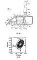
- Fig. 1 is an illustration of a variable compliance joystick according to the present invention
- Fig. 2 is an illustration of the variable compliance joystick of Fig. 1 , with the outer housing removed to show the internal components;
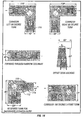
- Figs. 3A-3D are enlarged views of the compliance and damping components for the variable compliance joystick of Fig. 1 ;
- Fig. 4 is a graph illustrating sample data for dead-zone calculation with an ellipse superimposed
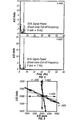
- Fig. 5 is a graph illustrating power spectral density estimates from data collected while the hand of a user is resting on the shaft of the variable compliance joystick of Fig. 1 , the low-pass filter frequency being shown for both axes;
- Fig. 6 illustrates bias axes (x', y') for a particular case in which the bias axes were not orthogonal;
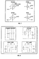
- Fig. 7 illustrates sample software templates, with the square template being the default template for the variable compliance joystick of Fig. 1 ;
- Fig. 8 illustrates virtual driving tasks performed by a user, with the desired path indicated in solid lines and the virtual walls being represented by dashed lines;
- Fig. 9 illustrates a user driving an electric powered wheelchair through a virtual environment for the wheelchair driving simulator according to the present invention
- Fig. 10 illustrates a setup for collecting modeling data
- Fig. 11 illustrates an example of a driving task and the corresponding motor graph (unimpaired hand control);
- Fig. 12 illustrates a motor graph of the same maneuver of Fig. 11 performed by an individual with cerebral palsy
- Fig. 13 illustrates an output signal produced by the variable gain algorithm
- Fig. 14 illustrates another example of virtual driving tasks performed by a user.
- Figs. 1-14 illustrate components and features of a variable compliance joystick 100 and associated systems according to the present invention.
- variable compliance joystick 100 with mechanical and software customization, and with an integrated control capability, and a method of systematically determining the best mechanical settings and compensatory algorithms to embed in joystick 100 to offer an individual with substantial upper extremity motor impairments a personal fit and maximum function.
- variable compliance joystick 100 may be used for driving Electric Powered Wheelchairs, for controlling additional rehabilitation technology, and for other related operations as discussed in detail below.
- variable compliance joystick 100 The aforementioned features of variable compliance joystick 100 and the method of systematically determining the best mechanical settings and compensatory algorithms to embed in joystick 100 will first be broadly described.
- variable compliance joystick 100 may generally be an isometric (force sensing) joystick, and contain an internal micro controller and memory.
- Joystick 100 may be operable in full isometric mode (no shaft movement), or alternatively, a flexible extension (i.e. a conical elastimer sheathe) may be added to the joystick shaft to create various levels of compliance (motion with spring return). If the flexible extension is hollow and filled with a viscous substance such as stiff modeling clay, a damping effect may be included as well.
- variable compliance joystick 100 may generally include a reprogrammable internal micro controller for intercepting and modifying the transducer signals generated by the joystick shaft. These transformations will hereinafter be referred to as "compensatory algorithms”.
- variable compliance joystick 100 may generally have the ability to operate a personal computer by functioning as a cordless joystick mouse.
- most current wheelchair joysticks only drive the wheelchair, and separate interfaces must be purchased and mounted if an individual wishes to operate other devices such as a personal computer.
- individuals with impaired hand use may only be able to reach and operate a single control interface, thus forcing them to obtain assistance when changing between devices. Therefore, by providing joystick 100 with the ability to operate a personal computer, in addition to wheelchair driving and computer access, joystick 100 may also be used to access devices such as voice output communication aids, environmental control systems etc.
- variable compliance joystick 100 may include a Wheelchair-Driving Simulator for determining the best joystick settings.
- a Wheelchair-Driving Simulator for determining the best joystick settings.
- current clinical practice for setting up an Electric Powered Wheelchair joystick is to mechanically mount the joystick on the side of the chair within the user's reach and then have the user practice driving around the clinic floor space. Based solely upon visual observation, the clinician makes changes to the wheelchair controller settings to improve wheelchair manageability.
- the Wheelchair-Driving Simulator for determining the best joystick settings may generally consist of a stationary wheelchair positioned in front of a large screen computer monitor.
- While practicing with joystick 100 the user may "drive” an onscreen wheelchair icon or "sprite” through a series of close-quarter maneuvers.
- the simulator program running on a desktop PC may monitor the sprite's path and score the driver's maneuvering skill.
- both the hardware settings and software algorithms of the joystick 100 may be modified to improve the client's driving ability.
- Hardware compliance and damping adjustments may be achieved by substituting different extension shafts on joystick 100.
- Compensatory algorithms may be invoked by selecting options contained on menus in the driving simulator program. In this manner, a therapist may rapidly try out a variety of mechanical and algorithm settings.
- the simulator may immediately stage a fresh sprite-driving task and objectively score the benefit of a particular mechanical setting or algorithm.
- the therapist may "fine tune" joystick 100 to the user's motor pattern.
- the final extension shaft may remain with the joystick and the final compensatory algorithms may be cross-compiled and downloaded into the joystick's internal micro controller memory, thus providing a user with a personalized joystick.
- Variable compliance joystick 100 and the method for systematically determining the best mechanical settings and compensatory algorithms to embed in joystick 100, will now be described in detail in reference to Figs. 1-14 .
- variable compliance joystick 100 may be designed such that it would appear similar to a conventional joystick and use commercial mounting and positioning hardware for an electric powered wheelchair.
- Joystick 100 may be used in full isometric mode or in a variable compliance mode, and include a housing 102 having a shaft 104 including a joystick tip 106 disposed on a top end thereof for operation by a user's fingertip.
- Shaft 104 may couple joystick tip 106 to an actuator plate fixed to a lower end of the shaft.
- the actuator plate may include horizontal arms extending radially from shaft 104, with the number of arms generally equaling the number of discrete force sensors (not shown), with each arm overlying a corresponding sensor.
- Joystick 100 may produce a voltage output proportional to the force exerted on shaft 104 by a user, and include printed circuit board 154 designed to fit within housing 102 for providing voltage regulation, bridging direct current excitation, bridging output signal amplification and low-pass filtering of the strain gage bridge signal.
- Joystick 100 may be operatively connected to an electric powered wheelchair 110.
- wheelchair 110 may operate on a 24 V dc system and use electromechanical parking brakes (not shown) that are normally closed (i.e. fully active) that release when power is applied to the motors.
- joystick 100 may obtain its power from batteries (not shown) and run on 12 V dc, or half the bus voltage.
- the output signal may include level shifting in order to be compatible with commercial analog electric powered wheelchair controllers.
- joystick 100 may include a serial or parallel port.
- Joystick 100 may contain an internal microcontroller with memory which uses compensatory algorithms to modify signals generated by the joystick forces on each strain gauge.
- a forward directed force on shaft 104 produces a forward motion of wheelchair 110 with speed proportional to the magnitude of the force.
- a rearward directed force on shaft 104 produces a rearward motion of wheelchair 110 with speed proportional to the magnitude of the force.
- Left and right forces on shaft 104 are used to turn wheelchair 110 in the direction of the applied force with the rate of turning being proportional to the magnitude of the force.
- a digital low-pass filter with a cut-off frequency of 6 Hz, for example, may be implemented as the default setting to reduce the effects of vibration and tremor.
- Joystick 100 may be designed for electric powered wheelchairs that use differential wheel speed to provide directional control. In such wheelchairs, front casters 112 may swivel as wheelchair 110 turns in response to changes in the speed of rear wheels 114.
- joystick 100 may generally include variable compliance and damping which can be modified to enhance operator control.
- Variable compliance which refers to the movement ease and springiness of shaft 104, generally refers to the spectrum of force versus motion.
- standard position-sensing joysticks produce output signals proportional to shaft directionality and angle of deflection. These joysticks move freely as no significant spring tension (other than a return spring) is supplied. Examples of common controls that sense position are computer trackballs, sliding volume controls on stereos and doorknobs, all of which are essentially movement driven. A separate set of control technologies exist that respond to force with little or no displacement.
- variable compliance is used when referring to this spectrum of force vs. motion.
- mid compliance controls are not common in the home, but are frequently found on motor vehicles. Examples of mid compliance controls include the brake and accelerator pedals on automobiles, or the control stick on an aircraft. Mid range compliance is designed into these controls to provide proprioceptive feedback (tactile sensation through pressure). This is especially important in situations where the operator must visually scan the surroundings and cannot observe the position of the control.
- variable compliance mode for joystick 100 allows motion of shaft 104 with mechanical resistance and spring return to restore shaft 104 to a central position when the operating force is removed. As shown in Figs. 3A-3D , compliance may be achieved by adding a flexible extension 136 to joystick shaft 104. Compliance provides tactile feedback which gives the operator an indication of joystick position, freeing the use of vision for maneuvering wheelchair 110. While conventional movement sensing and isometric joysticks are actually endpoints of a spectrum, such joysticks contain a continuum of movement/force ratios ranging from low compliance, (high force with very little movement), to high compliance, (low force with substantial movement).
- variable compliance joystick 100 may include shaft 104 including upper and lower shaft segments 130, 131, respectively, joined by a closed coil spring 132.
- the upper shaft segment 130 may be drilled and threaded to match the spring wire gage. Therefore, by turning handle 134 counterclockwise, progressively more of spring 132 may be exposed to increase the compliance. For example, as shown in Fig. 3A , in the full isometric setting, the ends of the two shaft segments 130, 131 are in contact and fully constrained by the backing flange, thus the spring having no effect.
- the upper shaft segment 130 may be turned several revolutions, thus allowing spring 132 to buckle under load for increasing the amount of movement associated with a given force.
- Damping refers to the introduction of friction, which varies with the velocity of shaft 104. Damping provides an additional mechanical modification that may improve proportional control, especially for individuals with athetoid cerebral palsy.
- an athetoid movement disorder is characterized by incessant, uncontrolled writhing motions, frequently accompanied by involuntary, explosive bursts of extreme muscular exertion. Accordingly, if an individual with athetosis attempts to operate a conventional proportional joystick, he will uncontrollably slam the stick hard against the stop ring.
- a damper as shown in Fig. 3D , is a frictional device in which the coefficient of friction increases with the velocity of the joystick.
- Damping may be accomplished with pneumatics, viscous fluids, electrorheological fluids, or by electric particle brakes.
- flexible extension 136 i.e. an elastimer sheathe disposed around shaft 104 may be provided to act as a variable damper.
- Flexible extension 136 may provide both compliance and damping for movement of shaft 104.
- the cross section of extension 136 may be relatively thick and provide the heavier damping required for the higher spring tension.
- Variable compliance joystick 100 may further include an elastimer backing flange 138, a clearance hole 140 and a tapered locking base 142.
- An enclosure 144 may be used to encase the various components of joystick 100.
- Joystick 100 may further include the following components, including an interface block 146 to mounting tube 148, an anchor plate 150 for joystick shaft 104, a cable 152 connectable to a power wheelchair controller (not shown), a printed circuit board 154 for strain gages, user status LCD panel 158, joystick power switch (push on-push off) 162, controller interface and user controls printed circuit board 166, an analog signal conditioning printed circuit board 168, a digital signal processing printed circuit board 170 and a computer mouse interface printed circuit board 172.
- additional damping may be achieved by filling extension 136 with a viscous substance (such as stiff modeling clay) for providing mechanical damping of motion.
- a scale similar to a micrometer thimble may be affixed above flexible extension 136.
- Upper shaft 130 may be engraved with ring rulings and a single longitudinal line (not shown) to allow reading and replicating compliance settings. By combining this physically adjustable compliance with the different gain and filter settings discussed below, a variety of unique joystick characteristics may be created.
- the wheelchair driving simulator illustrated in Fig. 9 may be used to evaluate the operational characteristics of a user and to adjust software and mechanical parameters of joystick 100 to determine the optimal driving configuration.
- the simulator may use a computer generated rendition of a wheelchair course displayed on a large-screen computer monitor and a stationary wheelchair placed before the monitor.
- the wheelchair may be fitted with a joystick, but instead of the joystick controlling motion of the wheelchair, the joystick may control the motion of a wheelchair icon on the monitor.
- the user may guide the wheelchair icon through a series of close-quarter maneuvers.
- the program may have the ability to load various compensatory algorithms and driving tasks.
- the therapist running the simulation may add compliance and damping to the test by attaching different extension shafts to joystick 100.
- the simulator may score each driving task, enabling the therapist to determine the optimal mechanical and software configuration for the user.
- the compensation algorithms may include dead-zone computation (joystick at rest). This section includes low-pass filtering to reduce effects of tremor-like motion.
- the compensation algorithms may further include a determination of optimal bias axes (i.e. left-right, forward-backward), gain for each axis, determining wheelchair speed in each direction, and software templates (i.e. mathematically generated, to control bias, complex shapes generated by changing a single parameter).
- an empirical kinematics database (EKD) of the user's current or "to be prescribed” electric powered wheelchair is preferably obtained and loaded onto the virtual driving system.
- EKD empirical kinematics database
- An EKD characterizes the movement behavior of an electric powered wheelchair as various joystick signals are applied. This data is needed so that the virtual wheelchair image on the simulator can be made to accelerate, decelerate and turn in the same manner as the actual vehicle.
- a virtual driving simulator may be used to train the user to effectively control the electric powered wheelchair through an iterative process.
- the user may be observed driving the virtual wheelchair while performing virtual tasks and the physical (compliance and damping) and algorithmic (software compensation) parameters of the joystick may be adjusted to maximize the user's driving capability.
- the final control parameters chosen during simulation may be embedded into joystick 100 mounted on an actual electric powered wheelchair.
- the user may be observed driving the physical wheelchair in a wheelchair activities driving laboratory to confirm that the parameters chosen carry over to real world driving.
- a control fitting evaluation may be conducted using a virtual (computer simulated) environment.
- the benefits for virtual fitting include opportunities for practice without injury risk, rapid adjustment of control parameters and the ability for a computer to record accurate performance data.
- the accuracy of the user's driving may be graphically displayed by generating "Motor Graphs" from the computer's stored time-series data.
- joystick input forces and movements may be continuously recorded as time-series data while the user drives.
- the forward and reverse joystick axes are plotted above the graph centerline.
- the region below the centerline may be used for plotting left and right turns.
- the height of any plotted segment may represent the magnitude of the force/movement being applied at that moment. Since forward and reverse data, as well as left and right data are mutually exclusive, there is no overlap in the graphs.
- Graphs, as shown in Fig. 11 reveal much about an individual's joystick interaction.
- Fig. 11 illustrates an exemplary driving trial taken from an actual study.
- an electric powered wheelchair 110 was driven from the starting position to a target 305 centimeters to the right.
- the user begins by applying strong forward and right forces to joystick 100 to quickly turn the chair about 130 degrees to the right. Approximately halfway through the maneuver, some left turn force was applied to straighten out the chair path and during the last third, forward power was decreased to halt the chair.
- This particular user had a lumbar spinal cord injury and very little hand impairment.
- Fig. 12 illustrates the control patterns generated by an individual with athetoid cerebral palsy while performing the same trial as for Fig. 11 .
- the raw signal recorded for Fig. 12 illustrates the many transients are apparent as the user drives. In prior studies where only the motion of the entire wheelchair was tracked, these transient signals would be hidden by the inertia of the chair and driver.
- Fig. 13 shows the same trial time-series after processing with a basic, variable gain algorithm, where the weaker signals have gain applied and the sharply spiked transients have been substantially attenuated, resulting in considerably smoother driving. It should be noted that this attenuation is not a fixed cut-off value but one that tracks the contours of the operator's original input. This improved signal is sent to the electric powered wheelchair controller. It should also be noted that any of the driving tasks illustrated herein may have motor graphs generated as they are performed. To judge whether a user is able to drive more accurately following an adjustment to one of his compensation algorithms, the user's motor graph may be compared to a graph generated by an electric powered wheelchair driver without movement disorders performing the same maneuver.
- the onscreen chair In order to create an Empirical Kinematics Database for a personal mobility vehicle, the onscreen chair must accelerate, turn and decelerate consistent with the user's actual test chair.
- the user's chair may be characterized by temporarily mounting friction driven shaft encoders 174 on the drive wheels, a joystick signal generator 176 and a laptop computer 178.
- a manikin 180 approximately equal to the user's weight may be strapped into the chair seat.
- Joystick signal generator 176 may then be activated to execute a prerecorded set of joystick signals covering representative directions and magnitudes.
- Computer 178 on the rear of chair 110 may record the joystick signals and the encoder data representing the chair's movement responses. From this session, an empirical kinematic database may be calculated.
- the onscreen wheelchair image used for virtual driving may be defined with variables to allow the drive wheel diameters, drive wheel span, caster diameters, wheelbase and caster fork offset values to be assigned.
- the joystick signal may be matched to the two nearest records in the EKD and the shaft encoder data fields read. The virtual motion may be interpolated from these two records.
- kinematic models of popular wheelchairs and scooters may be provided as part of the virtual software, the only adjustment needed would be to correct for the user's weight and possibly a different floor surface, i.e. the user may live in a home with wall to wall carpet.
- a series of basic joystick inputs without feedback as to driving performance in electric powered wheelchair 110 may be optimized.
- a user may be asked to rest his or her hand comfortably on shaft 104 of joystick 100. Thereafter, force data in the x and y directions may be collected for a predetermined interval (i.e. 30 seconds) while the user's hand is at rest on the joystick (i.e. no attempt to drive will be made).
- the user may then be asked to push shaft 104 in the y-direction (i.e. straight ahead) with a light push and hold, moderate push and hold, and maximum push and hold for a minimum period (i.e. 10 seconds each), during which time the forces in the x and y direction may be recorded.
- the user may then repeat these tasks by pulling in the minus y-direction (i.e. straight back).
- the user may also be asked to push shaft 104 forward for a predetermined interval (i.e. two minutes) at a force that is comfortable.
- the user may be asked to exert a force in the plus and minus x-direction (i.e. left and right).
- the user may be asked to push or pull lightly and hold, moderately and hold, and maximally and hold, in each direction for a predetermined interval (i.e. 10 seconds).
- the user may also exert a force at a comfortable level in both the left and right directions, each for a predetermined interval (i.e. two minutes).
- This force data may be used to determine the bias axes, maximum force frequency in the x and y directions, and to set the speed sensitivity. Based upon the force measurements recorded, the optimization software may calibrate the joystick software variables.
- variable compliance joystick 100 thus consists of five steps, which involve a series of basic joystick inputs without feedback as to driving performance in the electric powered wheelchair.
- the steps being, dead-zone calibration, filter frequency determination, bias axis adjustment, software template determination, and fatigue compensation, will now be described in detail.
- the resting force data may be used to set the "dead-zone" (i.e. the minimum range of x and y forces that need to be exceeded in order to produce motion of the wheelchair).
- the dead-zone may be calculated by the following equations:
- the aforementioned equations may be used in an algorithm to calculate the parameters to define an elliptical dead-zone fitted from the data for each user.
- the parameters that define the ellipse may be increased by 20%, for example, in order to ensure that there is no unintended input to the wheelchair controller, and to ensure that the power wheelchair brakes fully engage when the forces on shaft 104 are within the dead-zone. If the forces on shaft 104 are outside the dead-zone upon start-up of the controller, wheelchair 110 may not move and an error signal may be provided to the user. The user must restart the controller while the forces are in the dead-zone (i.e. lower forces or remove hand from shaft 104) for the controller to start. This would be a safety feature designed to prevent the wheelchair from lunging when powered-up.
- the data from the resting forces, fore-aft forces, and left-right forces may be used to determine the low-pass filter frequency, for example due to tremor or athetoid motion, in the x and y directions.
- Independent filters for the x and y forces may use second order digital Butterworth Filters having the following filter frequency:
- F y Hz min F stop y ( Hz ) , F forward y Hz , F reverse y Hz , F left y Hz , F right y Hz
- F x Hz min F stop x ( Hz ) , F forward x Hz , F reverse x Hz , F left x Hz , F right x Hz
- the optimal cut-off frequencies for the x and y force filters may be chosen as the minimum of the 95% power frequency for each of the test cases.
- a sample data set displaying the y-directional force in the frequency domain along with the boundary frequency at 95% is displayed.
- People with upper extremity impairments often have better control in a direction other than the orientation of the joystick axis.
- Limited ability to accommodate individual bias may be provided by using specialized mounting hardware and an iterative process to determine the most appropriate angle at which to position joystick 100.
- Joystick 100 may automatically calculate the bias axes and adjust the force outputs in software.
- the constant C is the dot product of the unit vectors along the direction of the forward-reverse and left-right bias axes. If the bias axis analysis provides viable solutions, software may transform the forward and turning axes for the wheelchair to be aligned with the bias axes.
- the bias axes may be calculated from the force data obtained when subjects are asked to exert forces fore, aft, left and right at low, moderate, and high levels.
- gains may be set by using the mean of the force values in the x and y direction, respectively, during the middle minute (30 seconds to 90 seconds) of the aforementioned two minute session of applying a force at a comfortable level. Gains may be calculated using the following equations:
- Gain y Range y controller_input f y comfort - f y dead - zone
- Gain y Range x controller_input f x comfort - f x dead - zone
- a linear gain may be used from the joystick forces, along the bias axes, to the wheelchair controller input signals.
- a nonlinear gain function may be used.
- the gains may be initiated using Equations 9 and 10 above.
- the software used to tune joystick 100 may permit adjusting the limits for forward and reverse speed, and left and right rate turning by using a sliding bar with a range of 10% to 150% of the initial value.
- step four software Templates are typically stamped or machined pieces of metal placed over joystick housing 102 to restrict the motion of shaft 104. Essentially, shaft 104 hits the wall of the template and is restricted from moving further. Templates may be used to control bias, decrease the throw of shaft 104, or reduce the degrees of freedom of movement thereof. Software templates may be incorporated into joystick 100, and may be based on the mathematics of super quadratics.
- Super quadratics use mathematical equations to describe complex shapes.
- the math behind super quadratics has its origin in computer graphics and data compression.
- the benefit of super quadratics is that a sliding bar (i.e. adjusting a single parameter) can be used to adjust the software template shape from a square, circle, cross, ellipse or diamond.
- complex templates can be generated for each user of joystick 100 in a simple understandable manner.
- the shape of the template may be displayed on a computer screen.
- a clinician may be allowed to rotate the axes of the template via a sliding bar to improve the user's performance.
- the desired template After the desired template has been selected, it may be downloaded into the memory of joystick 100.
- square, cross, circular and oval templates 118, 120, 122 and 124, respectively may be used.
- a computer monitor 116 may be moved in front of the user and positioned for optimum viewing.
- the user may be instructed to track a pseudo-randomly-moving 10 mm square object.
- the computer may record the user's hand forces/movements and convert them into motor performance graphs. By comparing these graphs, algorithm changes may be selected by the therapist, transformed into the appropriate micro code, and flashed onto the embedded processor's EEPROM memory.
- the calibration cycle may be repeated up to four times during a during a period of 90 minutes.
- the user may perform virtual driving with two different joysticks, each joystick being presented on a separate visit.
- Joysticks may be selected from a standard movement sensing joystick, a force sensing joystick with a standard algorithm known as Variable Gain Algorithm, variable compliance joystick 100 with the movement sensing personally fitted algorithm and the movement-sensing joystick with the movement sensing personally fitted algorithm.
- One of the four joystick-algorithm combinations may be randomly selected and mounted.
- the virtual driving program on the computer may be started, with an investigator presenting selected onscreen driving tasks to the user using a balanced randomization scheme.
- the computer may track the edge of the virtual electric powered wheelchair silhouette and beep if the user attempts to exceed the boundary.
- the exemplary tasks may be chosen from the ones illustrated in Fig. 14 .
- the correct procedure for executing each task may be explained, and the user may be allowed to drive each maneuver with the joystick three times at a relaxed pace for familiarization.
- the user may be instructed to perform each maneuver as fast as practical without letting the onscreen chair stray over the gray boundary, with the investigator advising the user that driving accuracy is more important than completion speed.
- the intended path for the onscreen chair may be marked with a dotted line.
- the computer may record the virtual chair's position and the forces or motions applied by the user to the joysticks may be recorded. Additionally, time required to complete each maneuver in milliseconds and the number of boundary violations may be recorded. Users may perform forty eight trials, for example, for data collection in a session lasting about seventy minutes (i.e. one joystick, times six driving maneuvers, times eight presentations of each maneuver).
- step five some diseases and disorders result in substantial changes in motor strength and control during the course of a day.
- a change in sensitivity may be programmed to take place over time. To determine the changes brought on by fatigue, users may be asked to repeat the virtual driving testing protocol at 10:00 am, 12:00 pm, and 2:00 pm, for three sessions in a virtual laboratory.
- the joystick's microcontroller may be used to log cumulative force-time activity (a cumulative integral) as a user performs successive trials. All forces may be logged as absolute values. For each user, parameters alpha and beta for the fatigue-scheduling algorithm depicted in Table-5 may be established.
- the gain may be increased until a point of diminishing returns occurs ( K max ) . If the gain is raised too high, tremor or other unintentional movement may be amplified to the point of becoming the limiting factor.
- a fatigue recovery algorithm may also be included based on the assumption that if the user stops driving and receives a rest break, the gain can be backed off. After a specified period, i.e. eight hours of inactivity, the fatigue gain compensation may be reset and only the customized algorithms used. By logging the accumulated force-time integral and including a recovery algorithm, individuals may be able to drive in the community in the future with an optimum gain setting throughout the day.
- a user may drive his/her personal electric powered wheelchair in an indoor and outdoor driving course known as The Wheelchair Driving Activities Laboratory (WDAL).
- the WDAL has been used in several previous studies performed herein to effectively evaluate new assistive technologies, especially wheelchairs and wheelchair controls, prior to evaluation in the "real-world".
- the WDAL includes indoor driving skills for driving in environments including as tile flooring, carpeting, a door threshold, a doorway, a hallway, model bathroom, and model kitchen.
- the WDAL outdoor driving tasks include an ADA ramp, bus docking area, curb-cut, sidewalk, and decking material. Users may be tested on all of these activities. Each user may be given the opportunity to practice each of the driving tasks, but not to practice the test course.
- users may undergo the testing protocol.
- a study clinician may be given the option to tune the algorithms during the respective practice sessions using the same procedure as in Phase Two.
- a study therapist or rehabilitation engineer may rate each user as being either safe or unsafe in performing each driving task. If a user performs all of the driving tasks safely, than they would progress to the testing phase. Users who are judged unsafe may have a maximum of two, one-hour remedial training sessions prior to testing, otherwise they may be discontinued.
- the setup for algorithm optimization for joystick 100 may include a computer monitor 116, for displaying virtual driving tasks on a wheelchair dynamometer.
- the driving tasks may be presented on monitor 116, and users may receive real-time feedback of their driving by viewing the sprite on the monitor screen.
- the motion of the sprite may be proportional to the actual rotation of the wheelchair wheels on the dynamometer.
- the sprite may flash and change color when it contacts a wall, and a running total of wall hits may be displayed on the screen of monitor 116.
- the driving tasks may be performed while driving forwards and then repeated while driving backwards for a total of eight driving trials (i.e. 4 tasks x 2 orientations).
- the driving tasks may be presented in the following order: (1) straight hallway, (2) left turn, (3) right turn, and (4) docking. Based upon previous studies, these tasks are preferred since they have been demonstrated to elicit differences in the driving performance of a wheelchair.
- the driving task order may be selected to allow user to learn with simple tasks and progress to more complex tasks.
- Joystick 100 may start with the software in the default setting (all speed and directional setting at their minimum, and the virtual template set as a cross aligned with the x and y axes). While users are performing the driving tasks with joystick 100, a study investigator may tune joystick 100 parameters (i.e. speed limits, turning limits, and the shape and orientation of the software template) to optimize each user's performance. A licensed therapist specializing in Assistive Technology or a rehabilitation engineer may observe each user while driving in the virtual environment. At the completion of each task, a study therapist may rate each user as either being safe or unsafe in performing the task. Users may move into the performance analysis process once they are able to perform all of the virtual driving tasks safely.
- the default setting all speed and directional setting at their minimum, and the virtual template set as a cross aligned with the x and y axes.
- the optimization process may be suspended.
- the joystick may be tested for compliance ISO 7176-14, a regulation for specifying the operation of control devices for use on electric powered wheelchairs. Both normal operation and foreseeable misuse may be tested in ISO 7176-14. This standard includes bench tests (i.e. low voltage operation, over voltage protection, connector quality) and driving performance tests (i.e., braking, acceleration).
- a computerized tracking system may be used to evaluate the use of devices for control of electric powered wheelchair 110.
- joystick 100 including compensation algorithms was compared to a conventional position-sensing joystick.
- the manual performance of each joystick was measured for five inexperienced electric powered wheelchair users and five experienced electric powered wheelchair users who have tetraplegia.
- the users with tetraplegia aged 32 to 50, had spinal cord injuries or dysfunctions at level C4-C6.
- Each joystick had a similar housing and handle, and each joystick was mounted in a position preferred by the user.
- a computer (not shown) recorded the speed of each wheel, computed the virtual position and orientation, and displayed this information on the screen in real-time. All users used conventional handles except for one user with tetraplegia, who used a T-shaped handle since he was unable to use the knot handle.
- the users used an electric powered wheelchair while stationary on a wheelchair dynamometer to simulate inertial effects. Operating the electric powered wheelchair with each joystick, the users followed two-dimensional driving tasks displayed on a computer monitor. A moving sprite displayed virtual motions of the electric powered wheelchair.
- the root mean square error (rmse) was computed as users followed a series of driving tasks while following a pre-defined desired path.
- a paired t-test (p ⁇ 0.05) showed no significant differences in the root mean square error between the two joysticks.
- joystick 100 with Compensation Algorithms was tested against existing wheelchair standards, and compared to a commercial position sensing joystick. When averaged across all users (both controls and impaired users), the root mean square tracking error and time to complete the driving course constructed on a level asphalt parking lot were not significantly different (i.e. p ⁇ 0.05) for the two joysticks. Results within a user, however, did show significance. Across all users, nevertheless, joystick 100 was superior to the conventional position sensing joystick for two tasks: driving straight and driving in a circle.
- Fitts' Law for target acquisition was extended to a continuously updated target.
- the extended Fitts' Law was used to examine electric powered wheelchair driving with a conventional position sensing joystick and variable compliance joystick 100.
- the test results showed significant differences (p ⁇ 0.05) among the two types of joysticks for selected measures of information processing capacity, movement time, root mean square error, and average velocity while performing turning maneuvers.
- variable compliance joystick 100 may be mechanically configurable and include variable compliance to full isometric to be adapted for best use by a user, and/or include damping to reduce effects of unwanted motion.
- Joystick 100 may incorporate compensation algorithms, including a dead-zone for determining an elliptical area where joystick 100 ignores input, and filtering to reduce effects of tremors and other spurious motions.
- the axes of motion need not be orthogonal, thus enabling the finding of the best directions for forward, reverse, left and right directions.
- Joystick 100 may also include software templates of various shapes generated with a single parameter.
- Joystick 100 may be used with the wheelchair simulator discussed above for facilitating the matching of joystick mechanical and software parameters to individual users.
- wheelchair simulator disclosed herein may have application to other vehicles, such as cars, scooters, remotely controlled vehicles and for robotics.
- Joystick 100 may also be used for wheelchair control, as discussed above, or for control of other applications such as for computer pointing application (mouse).
Abstract
Description
- This application claims benefit of priority of Provisional Application Serial No.
60/406,682, filed August 29, 2002 - The invention relates generally to electric powered wheelchairs, and, more particularly to an apparatus and method for customized control of an electric powered wheelchair.
- Position sensing devices are integral components of computing systems, the ubiquitous "mouse" being one of the best examples. Joysticks are also common, and find applications in computer games, medical devices, wheelchairs, robotics, aircraft, advanced vehicles, and other devices. Other examples of position sensing devices include trackballs and virtual reality equipment such as helmets, goggles, gloves, and foot pedals. The earliest joysticks were basically a simple arrangement of contact switches at four quadrants. Moving the joystick shaft away from its centered position closed one of the four switches, depending on the direction of movement. Springs connected to the joystick returned the device to a central position when the joystick was released. The resistance to motion, called compliance, that is provided by the springs could be provided or augmented by other means, such as having the joystick move through a viscous fluid.
- An improvement to the contact switch joystick was made by development of the position sensing joystick. In this arrangement, the joystick was coupled to two potentiometers mounted at right angles. Motion of the joystick produced voltages from the potentiometers that indicated the position of the joystick. Later variations of position sensing joysticks employed optical encoders to determine the joystick position, replacing potentiometers. Further refinements of position sensing joysticks included the addition of tactile and force feedback. Tactile feedback is a simple vibration generated when provided position information falls within some desired region. Force feedback devices actually apply forces to the joystick shaft, for example, pushing against the operator induced motion. Force feedback may be used to indicate to a robotic operator that contact with an object has been made. The force sensing, or isometric, joystick used strain gauges to measure forces applied to the joystick with no motion of the joystick required. An example of such a joystick is the miniature isometric joystick used on laptop computer keyboards.
- In view of the aforementioned developments, today's electric powered wheelchairs include several components for facilitating control of movement thereof, including proportional position sensing joysticks, electric powered wheelchair controllers, isometric joysticks, damped joystick controls, joysticks with corrective algorithms and integrated control features, and wheelchair driving simulators.
- Proportional position sensing joysticks for electric powered wheelchairs are known in the art and generally allow individuals with impaired mobility to drive such wheelchairs. Position sensing joysticks produce speed and direction signals proportional to the joystick's directionality and angle of deflection. It has been shown that such joysticks are inadequate for as many as 40% of potential wheelchair users, partly because they are built on a "one size fits all" philosophy. For example, current clinical practice is to have a user try out various commercially available position sensing joystick controls, and then select a handle and mounting position most compatible with the user's residual hand function. Frequently, none of the commercial position sensing joystick controls are suitable and the user is often downgraded to single switch head arrays rather than a proportional control system. While single switch technology can be operated with limited and imprecise limb movement, the result is generally a slow and awkward wheelchair control system.
- With regard to electric powered wheelchair controllers, such controllers generally include a power regulating circuit between the position sensing joystick and the wheelchair drive motors. Controllers translate the speed and direction signals from the user control (i.e. a joystick) into appropriate current levels that are applied to the drive motors of a wheelchair. Over the years, the improvement and perfection of such controllers has been a focus of the wheelchair industry. Early controllers generally included simple driving algorithms, an example of which includes a controller operated by a driver pushing a position sensing joystick to the right or left, at which time the controller decided whether to merely slow the wheel inside the turn or, in the event of a sharp, low speed turn, to run the inside wheel in reverse to produce a tighter turning circle. In more modem controllers, in order to safely match an electric powered wheelchair to different driving abilities of particular users, manufacturers provide several adjustments on their controllers that a vendor or clinician may set with a hand held programmer. An exemplary adjustment may include adjustment of the maximum velocity the wheelchair will achieve during straight ahead or turning maneuvers. Modern controllers also include advanced algorithms to stabilize a wheelchair in hazardous terrain, such as during climbing or descending steep grades, or when traversing a cross slope. Even in light of the aforementioned improvements in controllers, commercial controllers and position sensing joysticks are generally unable to recognize or in any way correct for an operator's unintentional hand movements. Another major disadvantage of currently available controllers is that they only serve the electric powered wheelchair, and do not support the control of any other associated device, such as personal computers or environmental control systems.
- With regard to isometric joysticks, as discussed above, such joysticks are generally used with personal computers. A well-known example of an isometric joystick includes the "eraser head" mouse used on many laptop computers. While such joysticks are known in the industry, these joysticks have had limited application in the field of electric powered wheelchairs due to the associated limitations in the ability of user to adequately operate the joystick.
- With regard to damped joystick control, while such a methodology is known in the industry, damped control for joysticks has generally been used in the reduction of hand tremor. Moreover, the damped control methodology has primarily been used for position sensing, and not for control of electric powered wheelchairs.
- Lastly, with regard to wheelchair driving simulators, while simulators have indeed found applications in the automotive field, as with automobile driving simulators, for example, such simulators are however not applicable to wheelchair driving. Moreover, no known driving simulators have been used to tune electric powered wheelchairs or associated joysticks.
- Accordingly, there remains a need for a customizable and versatile control technology for electric powered wheelchairs. There also remains a need for a variable compliance joystick for electric powered wheelchair control and for facilitating the customization of the aforementioned technologies for users with various disabilities.
[0011a]US 6201196 describes a joystick assembly which can receive inputs from a user with very small displacement of the input handle so that the joystick can be used in a fatigue-free manner with a minimal use of force.
[0011b]WO 05/37252 - The invention solves the problems and overcomes the drawbacks and deficiencies of the prior art wheelchair control and simulation systems by providing an apparatus and method for customized control of electric powered wheelchairs.
- An aim of the invention is to provide a variable compliance joystick with mechanical and software customization, and with an integrated control capability.
- Another aim of the invention is to provide a method of systematically determining the best mechanical settings and compensatory algorithms to embed in the joystick to offer an individual with substantial upper extremity motor impairments a person fit and maximum function.
- Yet another aim of the invention is to provide a custom ized joystick that can be closely matched to user needs by use of a simulator to optimize software and hardware characteristics of the joystick.
- According to the present invention there is provided a joystick apparatus comprising:
- a rigid shaft including a tip, a base and a central longitudinal axis; and
- a flexible extension operatively connected to said shaft to vary the compliance of said shaft for transverse movement relative to said central longitudinal axis;
- said extension includes a frusto-conical cross-section with a larger diameter section disposed adjacent said base of said shaft and a smaller diameter section disposed adjacent said tip of said shaft;
- said shaft includes upper and lower shaft segments, said segments include a resilient member disposed between adjacent ends thereof and said segments are adjustable to be spaced away from each other for varying the compliance of said shaft, and wherein said extension is hollow and encircles said upper and lower shaft segments.
- The joystick may further include compensation algorithms including an elliptical dead-zone representative of the joystick shaft at rest, the dead-zone representing a minimum range of forces which must be exceeded to produce motion of an electric powered wheelchair including the joystick mounted thereon, the dead-zone further representing a maximum range of forces which must not be exceeded to prevent movement of the wheelchair. The compensation algorithms may include a determination of an optimal bias axes gain for movement of the joystick shaft in left, right, forward and backward directions. The compensation algorithms may also include at least one software template for at least one of controlling bias of the joystick shaft, decreasing throw of the joystick shaft and reducing degrees of freedom of an output signal of the joystick shaft. The software template may be based upon the mathematics of super quadratics, and may be one of a square, circular, cross, elliptical and diamond shaped template. The compensation algorithms may also include filtering to reduce the effects of unwanted motions of the joystick shaft.
- According to a second aspect of the present invention there is provided a method for systematically determ in ing the best mechanical settings and compensatory algorithms to embed in a joystick to offer a user a personal fit and maximum function, said joystick comprising a rigid shaft including a tip, a base and a central longitudinal axis, and a flexible extension operatively connected to said shaft to vary the compliance of said shaft for transverse movement relative to said central longitudinal axis, wherein said extension includes a frusto-conical cross-section with a larger diameter section disposed adjacent said base of said shaft and a smaller diameter section disposed adjacent said tip of said shaft, wherein said shaft includes upper and lower shaft segments, said segments include a resilient member disposed between adjacent ends thereof and said segments are adjustable to be spaced away from each other for varying the compliance of said shaft, and wherein said extension is hollow and encircles said upper and lower shaft segments, said method comprising:
- providing the user access to operate the joystick;
- operatively connecting the joystick to a driving simulator;
- displaying an icon on said driving simulator;
- controlling movement of said icon by the joystick;
- evaluating performance of the user based upon the user's ability to control movement of said icon; and
- modifying hardware settings for the joystick based upon said evaluation by substituting different flexible extensions for varying compliance of a joystick shaft including a central longitudinal axis, the extensions being operatively connected to said shaft to encircle said shaft to vary the compliance of said shaft for transverse movement relative to said central longitudinal axis, and modifying software algorithms for the joystick based upon said evaluation.
- For the method described above, modifying hardware settings may include substituting different flexible extensions for varying compliance of a joystick shaft, the extensions being operatively connected to the shaft to encircle the shaft, the extensions further including a frusto-conical cross-section. Modifying the software algorithms may include computing an elliptical dead-zone representation of a joystick shaft at rest, the dead-zone representing a minimum range of forces which must be exceeded to produce motion of an electric powered wheelchair including the joystick mounted thereon, the dead-zone further representing a maximum range of forces which must not be exceeded to prevent movement of the wheelchair. Modifying the software algorithms may include determining an optimal bias axes gain for movement of a joystick shaft in left, right, forward and backward directions. Modifying the software algorithms may include providing at least one software template for at least one of controlling bias of a joystick shaft, decreasing throw of the joystick shaft and reducing degrees of freedom of an output signal of the joystick shaft. The software template may be based upon mathematics of super quadratics, and may be one of a square, circular, cross, elliptical and diamond shaped template. Modifying at least one of the hardware settings and software algorithms may include obtaining a plurality of joystick shaft inputs corresponding to driving performance of an electric powered wheelchair having the joystick mounted thereon.
- Additional features, advantages, and embodiments of the invention may be set forth or apparent from consideration of the following detailed description, drawings and claims. Moreover, it is to be understood that both the foregoing summary of the invention and the following detailed description are exemplary and intended to provide further explanation of the invention
- The accompanying drawings, which are included to provide a further understanding of the invention and are incorporated in and constitute a part of this specification, illustrate preferred embodiments of the invention and together with the detail description serve to explain the principles of the invention. In the drawings:
-
Fig. 1 is an illustration of a variable compliance joystick according to the present invention; -
Fig. 2 is an illustration of the variable compliance joystick ofFig. 1 , with the outer housing removed to show the internal components; -
Figs. 3A-3D are enlarged views of the compliance and damping components for the variable compliance joystick ofFig. 1 ; -
Fig. 4 is a graph illustrating sample data for dead-zone calculation with an ellipse superimposed; -
Fig. 5 is a graph illustrating power spectral density estimates from data collected while the hand of a user is resting on the shaft of the variable compliance joystick ofFig. 1 , the low-pass filter frequency being shown for both axes; -
Fig. 6 illustrates bias axes (x', y') for a particular case in which the bias axes were not orthogonal; -
Fig. 7 illustrates sample software templates, with the square template being the default template for the variable compliance joystick ofFig. 1 ; -
Fig. 8 illustrates virtual driving tasks performed by a user, with the desired path indicated in solid lines and the virtual walls being represented by dashed lines; -
Fig. 9 illustrates a user driving an electric powered wheelchair through a virtual environment for the wheelchair driving simulator according to the present invention; -
Fig. 10 illustrates a setup for collecting modeling data; -
Fig. 11 illustrates an example of a driving task and the corresponding motor graph (unimpaired hand control); -
Fig. 12 illustrates a motor graph of the same maneuver ofFig. 11 performed by an individual with cerebral palsy; -
Fig. 13 illustrates an output signal produced by the variable gain algorithm; and -
Fig. 14 illustrates another example of virtual driving tasks performed by a user. - Referring now to the drawings wherein like reference numerals designate corresponding parts throughout the several views,
Figs. 1-14 illustrate components and features of avariable compliance joystick 100 and associated systems according to the present invention. - Specifically, as illustrated in
Figs. 1-14 , the present invention provides avariable compliance joystick 100 with mechanical and software customization, and with an integrated control capability, and a method of systematically determining the best mechanical settings and compensatory algorithms to embed injoystick 100 to offer an individual with substantial upper extremity motor impairments a personal fit and maximum function. Generally,variable compliance joystick 100 may be used for driving Electric Powered Wheelchairs, for controlling additional rehabilitation technology, and for other related operations as discussed in detail below. - The aforementioned features of
variable compliance joystick 100 and the method of systematically determining the best mechanical settings and compensatory algorithms to embed injoystick 100 will first be broadly described. - With regard to mechanical customization, as discussed in greater detail below,
variable compliance joystick 100 may generally be an isometric (force sensing) joystick, and contain an internal micro controller and memory.Joystick 100 may be operable in full isometric mode (no shaft movement), or alternatively, a flexible extension (i.e. a conical elastimer sheathe) may be added to the joystick shaft to create various levels of compliance (motion with spring return). If the flexible extension is hollow and filled with a viscous substance such as stiff modeling clay, a damping effect may be included as well. - With regard to software customization, as discussed in greater detail below,
variable compliance joystick 100 may generally include a reprogrammable internal micro controller for intercepting and modifying the transducer signals generated by the joystick shaft. These transformations will hereinafter be referred to as "compensatory algorithms". - With regard to integrated control capability, as discussed in greater detail below,
variable compliance joystick 100 may generally have the ability to operate a personal computer by functioning as a cordless joystick mouse. For example, most current wheelchair joysticks only drive the wheelchair, and separate interfaces must be purchased and mounted if an individual wishes to operate other devices such as a personal computer. Moreover, individuals with impaired hand use may only be able to reach and operate a single control interface, thus forcing them to obtain assistance when changing between devices. Therefore, by providingjoystick 100 with the ability to operate a personal computer, in addition to wheelchair driving and computer access,joystick 100 may also be used to access devices such as voice output communication aids, environmental control systems etc. - Lastly, with regard to the method of systematically determining the best mechanical settings and compensatory algorithms to embed in
joystick 100 to offer an individual with substantial upper extremity motor impairments a personal fit and maximum function, as discussed in greater detail below,variable compliance joystick 100 may include a Wheelchair-Driving Simulator for determining the best joystick settings. For example, current clinical practice for setting up an Electric Powered Wheelchair joystick is to mechanically mount the joystick on the side of the chair within the user's reach and then have the user practice driving around the clinic floor space. Based solely upon visual observation, the clinician makes changes to the wheelchair controller settings to improve wheelchair manageability. The Wheelchair-Driving Simulator for determining the best joystick settings may generally consist of a stationary wheelchair positioned in front of a large screen computer monitor. While practicing withjoystick 100, the user may "drive" an onscreen wheelchair icon or "sprite" through a series of close-quarter maneuvers. The simulator program running on a desktop PC may monitor the sprite's path and score the driver's maneuvering skill. During the evaluation phase, both the hardware settings and software algorithms of thejoystick 100 may be modified to improve the client's driving ability. Hardware compliance and damping adjustments may be achieved by substituting different extension shafts onjoystick 100. Compensatory algorithms may be invoked by selecting options contained on menus in the driving simulator program. In this manner, a therapist may rapidly try out a variety of mechanical and algorithm settings. The simulator may immediately stage a fresh sprite-driving task and objectively score the benefit of a particular mechanical setting or algorithm. Through this iterative process, the therapist may "fine tune"joystick 100 to the user's motor pattern. When the most useful customizations have been determined, the final extension shaft may remain with the joystick and the final compensatory algorithms may be cross-compiled and downloaded into the joystick's internal micro controller memory, thus providing a user with a personalized joystick. -
Variable compliance joystick 100 and the method for systematically determining the best mechanical settings and compensatory algorithms to embed injoystick 100, will now be described in detail in reference toFigs. 1-14 . - Specifically, as shown in
Figs. 1 and 2 ,variable compliance joystick 100 may be designed such that it would appear similar to a conventional joystick and use commercial mounting and positioning hardware for an electric powered wheelchair.Joystick 100 may be used in full isometric mode or in a variable compliance mode, and include ahousing 102 having ashaft 104 including ajoystick tip 106 disposed on a top end thereof for operation by a user's fingertip.Shaft 104 may couplejoystick tip 106 to an actuator plate fixed to a lower end of the shaft. The actuator plate may include horizontal arms extending radially fromshaft 104, with the number of arms generally equaling the number of discrete force sensors (not shown), with each arm overlying a corresponding sensor. -
Joystick 100 may produce a voltage output proportional to the force exerted onshaft 104 by a user, and include printedcircuit board 154 designed to fit withinhousing 102 for providing voltage regulation, bridging direct current excitation, bridging output signal amplification and low-pass filtering of the strain gage bridge signal.Joystick 100 may be operatively connected to an electricpowered wheelchair 110. As with conventional electric powered wheelchairs,wheelchair 110 may operate on a 24 V dc system and use electromechanical parking brakes (not shown) that are normally closed (i.e. fully active) that release when power is applied to the motors. In the embodiment ofFig. 1 ,joystick 100 may obtain its power from batteries (not shown) and run on 12 V dc, or half the bus voltage. The output signal may include level shifting in order to be compatible with commercial analog electric powered wheelchair controllers. Alternatively, for digital electric powered wheelchair controllers,joystick 100 may include a serial or parallel port.Joystick 100 may contain an internal microcontroller with memory which uses compensatory algorithms to modify signals generated by the joystick forces on each strain gauge. - In operation, a forward directed force on
shaft 104 produces a forward motion ofwheelchair 110 with speed proportional to the magnitude of the force. Likewise, a rearward directed force onshaft 104 produces a rearward motion ofwheelchair 110 with speed proportional to the magnitude of the force. Left and right forces onshaft 104 are used to turnwheelchair 110 in the direction of the applied force with the rate of turning being proportional to the magnitude of the force. A digital low-pass filter with a cut-off frequency of 6 Hz, for example, may be implemented as the default setting to reduce the effects of vibration and tremor.Joystick 100 may be designed for electric powered wheelchairs that use differential wheel speed to provide directional control. In such wheelchairs,front casters 112 may swivel aswheelchair 110 turns in response to changes in the speed ofrear wheels 114. - As discussed above,
joystick 100 may generally include variable compliance and damping which can be modified to enhance operator control. Variable compliance, which refers to the movement ease and springiness ofshaft 104, generally refers to the spectrum of force versus motion. For example, standard position-sensing joysticks produce output signals proportional to shaft directionality and angle of deflection. These joysticks move freely as no significant spring tension (other than a return spring) is supplied. Examples of common controls that sense position are computer trackballs, sliding volume controls on stereos and doorknobs, all of which are essentially movement driven. A separate set of control technologies exist that respond to force with little or no displacement. As discussed above, these devices are collectively called isometric controls, one of which is the common "eraser head" mouse, which appears in the center of the keyboard on many laptop computers. Another example is the membrane keypad used on microwave ovens to simplify cleaning, in which traditional push buttons are replaced with sealed force-sensing switches. What is not obvious is that position sensing and force-sensing controls merely represent the endpoints of a continuum of control designs. Thus the term variable compliance is used when referring to this spectrum of force vs. motion. For example, mid compliance controls are not common in the home, but are frequently found on motor vehicles. Examples of mid compliance controls include the brake and accelerator pedals on automobiles, or the control stick on an aircraft. Mid range compliance is designed into these controls to provide proprioceptive feedback (tactile sensation through pressure). This is especially important in situations where the operator must visually scan the surroundings and cannot observe the position of the control. - The variable compliance mode for
joystick 100 allows motion ofshaft 104 with mechanical resistance and spring return to restoreshaft 104 to a central position when the operating force is removed. As shown inFigs. 3A-3D , compliance may be achieved by adding aflexible extension 136 tojoystick shaft 104. Compliance provides tactile feedback which gives the operator an indication of joystick position, freeing the use of vision for maneuveringwheelchair 110. While conventional movement sensing and isometric joysticks are actually endpoints of a spectrum, such joysticks contain a continuum of movement/force ratios ranging from low compliance, (high force with very little movement), to high compliance, (low force with substantial movement). Accordingly,variable compliance joystick 100 may includeshaft 104 including upper andlower shaft segments closed coil spring 132. Theupper shaft segment 130 may be drilled and threaded to match the spring wire gage. Therefore, by turninghandle 134 counterclockwise, progressively more ofspring 132 may be exposed to increase the compliance. For example, as shown inFig. 3A , in the full isometric setting, the ends of the twoshaft segments Fig. 3B , theupper shaft segment 130 may be turned several revolutions, thus allowingspring 132 to buckle under load for increasing the amount of movement associated with a given force. Lastly, for the high compliance setting shown inFig. 3C , additional spring length may been exposed by further turninghandle 134 to allowupper shaft 130 to buckle relative tolower shaft segment 131. It should be noted thatshaft 104 becomes longer as compliance is increased. This increase in length can be compensated by machining a long threaded hole (not shown) insidehandle 134 and counter rotating the handle to correct for the length increase. - Damping refers to the introduction of friction, which varies with the velocity of
shaft 104. Damping provides an additional mechanical modification that may improve proportional control, especially for individuals with athetoid cerebral palsy. For example, an athetoid movement disorder is characterized by incessant, uncontrolled writhing motions, frequently accompanied by involuntary, explosive bursts of extreme muscular exertion. Accordingly, if an individual with athetosis attempts to operate a conventional proportional joystick, he will uncontrollably slam the stick hard against the stop ring. A damper, as shown inFig. 3D , is a frictional device in which the coefficient of friction increases with the velocity of the joystick. If a tremor or athetoid movement is characterized by a higher frequency than volitional movement, a damper will tend to attenuate the unwanted movement while preserving the volitional movement, thus providing a means of increasing the signal to noise ratio. Damping may be accomplished with pneumatics, viscous fluids, electrorheological fluids, or by electric particle brakes. - In the embodiment of
Fig. 3D , flexible extension 136 (i.e. an elastimer sheathe) disposed aroundshaft 104 may be provided to act as a variable damper.Flexible extension 136 may provide both compliance and damping for movement ofshaft 104. For example, in the mid range compliance region forFig. 3B , the cross section ofextension 136 may be relatively thick and provide the heavier damping required for the higher spring tension.Variable compliance joystick 100 may further include anelastimer backing flange 138, aclearance hole 140 and atapered locking base 142. Anenclosure 144 may be used to encase the various components ofjoystick 100.Joystick 100 may further include the following components, including aninterface block 146 to mountingtube 148, ananchor plate 150 forjoystick shaft 104, acable 152 connectable to a power wheelchair controller (not shown), a printedcircuit board 154 for strain gages, userstatus LCD panel 158, joystick power switch (push on-push off) 162, controller interface and user controls printedcircuit board 166, an analog signal conditioning printedcircuit board 168, a digital signal processing printedcircuit board 170 and a computer mouse interface printedcircuit board 172. Alternatively, additional damping may be achieved by fillingextension 136 with a viscous substance (such as stiff modeling clay) for providing mechanical damping of motion. - In operation, as
handle 134 is turned counterclockwise toward higher compliances (movement sensing region), as shown inFig. 3C , the spring tension decreases. At this stage, the thinner region offlexible extension 136 is engaged and less damping is imposed onshaft 104. - As shown in
Fig. 3C , a scale similar to a micrometer thimble may be affixed aboveflexible extension 136.Upper shaft 130 may be engraved with ring rulings and a single longitudinal line (not shown) to allow reading and replicating compliance settings. By combining this physically adjustable compliance with the different gain and filter settings discussed below, a variety of unique joystick characteristics may be created. - The method of systematically determining the optimal settings for
variable compliance joystick 100 by means of a wheelchair driving simulator will next be described in detail in reference toFigs. 4-14 . The wheelchair driving simulator illustrated inFig. 9 , may be used to evaluate the operational characteristics of a user and to adjust software and mechanical parameters ofjoystick 100 to determine the optimal driving configuration. As discussed in greater detail below, the simulator may use a computer generated rendition of a wheelchair course displayed on a large-screen computer monitor and a stationary wheelchair placed before the monitor. The wheelchair may be fitted with a joystick, but instead of the joystick controlling motion of the wheelchair, the joystick may control the motion of a wheelchair icon on the monitor. The user may guide the wheelchair icon through a series of close-quarter maneuvers. The program may have the ability to load various compensatory algorithms and driving tasks. The therapist running the simulation may add compliance and damping to the test by attaching different extension shafts tojoystick 100. The simulator may score each driving task, enabling the therapist to determine the optimal mechanical and software configuration for the user. The compensation algorithms may include dead-zone computation (joystick at rest). This section includes low-pass filtering to reduce effects of tremor-like motion. The compensation algorithms may further include a determination of optimal bias axes (i.e. left-right, forward-backward), gain for each axis, determining wheelchair speed in each direction, and software templates (i.e. mathematically generated, to control bias, complex shapes generated by changing a single parameter). - Software compensation algorithms may be applied to the signals emanating from the joystick transducers. These can be either an alternative or an addition to the aforementioned mechanical variable compliance or damping intervention techniques discussed previously.
- The three phases (i.e. Phase One, Phase Two and Phase Three) for the optimization of
variable compliance joystick 100 will now be described. - Generally, for Phase One, because the fitting of
joystick 100 is carried out in a virtual setting, an empirical kinematics database (EKD) of the user's current or "to be prescribed" electric powered wheelchair is preferably obtained and loaded onto the virtual driving system. An EKD characterizes the movement behavior of an electric powered wheelchair as various joystick signals are applied. This data is needed so that the virtual wheelchair image on the simulator can be made to accelerate, decelerate and turn in the same manner as the actual vehicle. For Phase Two, a virtual driving simulator may be used to train the user to effectively control the electric powered wheelchair through an iterative process. The user may be observed driving the virtual wheelchair while performing virtual tasks and the physical (compliance and damping) and algorithmic (software compensation) parameters of the joystick may be adjusted to maximize the user's driving capability. For Phase Three, the final control parameters chosen during simulation may be embedded intojoystick 100 mounted on an actual electric powered wheelchair. The user may be observed driving the physical wheelchair in a wheelchair activities driving laboratory to confirm that the parameters chosen carry over to real world driving. - Specifically, for Phase One, a control fitting evaluation may be conducted using a virtual (computer simulated) environment. The benefits for virtual fitting include opportunities for practice without injury risk, rapid adjustment of control parameters and the ability for a computer to record accurate performance data. The accuracy of the user's driving may be graphically displayed by generating "Motor Graphs" from the computer's stored time-series data.
- For Motor Graphs, joystick input forces and movements may be continuously recorded as time-series data while the user drives. As illustrated in
Fig. 11 , for the graphical method for displaying these data, the forward and reverse joystick axes are plotted above the graph centerline. The region below the centerline may be used for plotting left and right turns. The height of any plotted segment may represent the magnitude of the force/movement being applied at that moment. Since forward and reverse data, as well as left and right data are mutually exclusive, there is no overlap in the graphs. Graphs, as shown inFig. 11 , reveal much about an individual's joystick interaction. - Specifically,
Fig. 11 illustrates an exemplary driving trial taken from an actual study. During the particular trial forFig. 11 , an electricpowered wheelchair 110 was driven from the starting position to atarget 305 centimeters to the right. The user begins by applying strong forward and right forces tojoystick 100 to quickly turn the chair about 130 degrees to the right. Approximately halfway through the maneuver, some left turn force was applied to straighten out the chair path and during the last third, forward power was decreased to halt the chair. This particular user had a lumbar spinal cord injury and very little hand impairment. -
Fig. 12 , illustrates the control patterns generated by an individual with athetoid cerebral palsy while performing the same trial as forFig. 11 . The raw signal recorded forFig. 12 illustrates the many transients are apparent as the user drives. In prior studies where only the motion of the entire wheelchair was tracked, these transient signals would be hidden by the inertia of the chair and driver. - Lastly,
Fig. 13 shows the same trial time-series after processing with a basic, variable gain algorithm, where the weaker signals have gain applied and the sharply spiked transients have been substantially attenuated, resulting in considerably smoother driving. It should be noted that this attenuation is not a fixed cut-off value but one that tracks the contours of the operator's original input. This improved signal is sent to the electric powered wheelchair controller. It should also be noted that any of the driving tasks illustrated herein may have motor graphs generated as they are performed. To judge whether a user is able to drive more accurately following an adjustment to one of his compensation algorithms, the user's motor graph may be compared to a graph generated by an electric powered wheelchair driver without movement disorders performing the same maneuver. - In order for the virtual fitting for Phase One to be meaningful, it is essential that an accurate kinematics model of the actual mobility vehicle be obtained. The steering response, acceleration and deceleration of the virtual vehicle must closely match the prescribed real world vehicle.
- In order to create an Empirical Kinematics Database for a personal mobility vehicle, the onscreen chair must accelerate, turn and decelerate consistent with the user's actual test chair. As shown in
Fig. 10 , the user's chair may be characterized by temporarily mounting friction drivenshaft encoders 174 on the drive wheels, ajoystick signal generator 176 and alaptop computer 178. Amanikin 180 approximately equal to the user's weight may be strapped into the chair seat.Joystick signal generator 176 may then be activated to execute a prerecorded set of joystick signals covering representative directions and magnitudes.Computer 178 on the rear ofchair 110 may record the joystick signals and the encoder data representing the chair's movement responses. From this session, an empirical kinematic database may be calculated. - The onscreen wheelchair image used for virtual driving may be defined with variables to allow the drive wheel diameters, drive wheel span, caster diameters, wheelbase and caster fork offset values to be assigned. To interpret a joystick action entered during virtual driving, the joystick signal may be matched to the two nearest records in the EKD and the shaft encoder data fields read. The virtual motion may be interpolated from these two records.
- Continuing with Phase One, kinematic models of popular wheelchairs and scooters may be provided as part of the virtual software, the only adjustment needed would be to correct for the user's weight and possibly a different floor surface, i.e. the user may live in a home with wall to wall carpet.
- Thus, for Phase One, a series of basic joystick inputs without feedback as to driving performance in electric
powered wheelchair 110 may be optimized. In order to accomplish this, a user may be asked to rest his or her hand comfortably onshaft 104 ofjoystick 100. Thereafter, force data in the x and y directions may be collected for a predetermined interval (i.e. 30 seconds) while the user's hand is at rest on the joystick (i.e. no attempt to drive will be made). The user may then be asked to pushshaft 104 in the y-direction (i.e. straight ahead) with a light push and hold, moderate push and hold, and maximum push and hold for a minimum period (i.e. 10 seconds each), during which time the forces in the x and y direction may be recorded. The user may then repeat these tasks by pulling in the minus y-direction (i.e. straight back). The user may also be asked to pushshaft 104 forward for a predetermined interval (i.e. two minutes) at a force that is comfortable. Next, the user may be asked to exert a force in the plus and minus x-direction (i.e. left and right). The user may be asked to push or pull lightly and hold, moderately and hold, and maximally and hold, in each direction for a predetermined interval (i.e. 10 seconds). The user may also exert a force at a comfortable level in both the left and right directions, each for a predetermined interval (i.e. two minutes). This force data may be used to determine the bias axes, maximum force frequency in the x and y directions, and to set the speed sensitivity. Based upon the force measurements recorded, the optimization software may calibrate the joystick software variables. - As briefly discussed above, the optimization of the
variable compliance joystick 100 thus consists of five steps, which involve a series of basic joystick inputs without feedback as to driving performance in the electric powered wheelchair. The steps being, dead-zone calibration, filter frequency determination, bias axis adjustment, software template determination, and fatigue compensation, will now be described in detail. - Specifically, for step one, the resting force data may be used to set the "dead-zone" (i.e. the minimum range of x and y forces that need to be exceeded in order to produce motion of the wheelchair). The dead-zone may be calculated by the following equations:
-

-

- where:
-

- Using the least squares criteria:
-

- where:
-

- The variables definitions for Equations 1-5 are listed in Table-1.
- Referring to
Fig. 4 , the aforementioned equations may be used in an algorithm to calculate the parameters to define an elliptical dead-zone fitted from the data for each user. The parameters that define the ellipse may be increased by 20%, for example, in order to ensure that there is no unintended input to the wheelchair controller, and to ensure that the power wheelchair brakes fully engage when the forces onshaft 104 are within the dead-zone.
If the forces onshaft 104 are outside the dead-zone upon start-up of the controller,wheelchair 110 may not move and an error signal may be provided to the user. The user must restart the controller while the forces are in the dead-zone (i.e. lower forces or remove hand from shaft 104) for the controller to start. This would be a safety feature designed to prevent the wheelchair from lunging when powered-up. - For step two, the data from the resting forces, fore-aft forces, and left-right forces may be used to determine the low-pass filter frequency, for example due to tremor or athetoid motion, in the x and y directions. Independent filters for the x and y forces may use second order digital Butterworth Filters having the following filter frequency:
-

-

- The variables definitions for the above-identified filter frequency are listed in Table-2.
- The optimal cut-off frequencies for the x and y force filters may be chosen as the minimum of the 95% power frequency for each of the test cases. Referring to
Fig. 5 , a sample data set displaying the y-directional force in the frequency domain along with the boundary frequency at 95% is displayed. People with upper extremity impairments often have better control in a direction other than the orientation of the joystick axis. Limited ability to accommodate individual bias may be provided by using specialized mounting hardware and an iterative process to determine the most appropriate angle at which to positionjoystick 100.Joystick 100 may automatically calculate the bias axes and adjust the force outputs in software. - An additional advantage of the
joystick 100 is that the x and y axes do not need to be orthogonal as with current joysticks, hence, individual bias axes may be calculated for the forward and turning axes ofwheelchair 110. Therefore, for step three, the bias axes may be calculated using the following equations, and thereafter adjusted: - Straight Test (forward and reverse):
-

- Turning Test (left and right):
-

- Test to measure if axes are orthogonal:
-

- The variables definitions for Equations 6-8 are listed in Table-3.
- Referring to
Fig. 6 , in the above-identified method of calculating the bias axes, the constant C is the dot product of the unit vectors along the direction of the forward-reverse and left-right bias axes. If the bias axis analysis provides viable solutions, software may transform the forward and turning axes for the wheelchair to be aligned with the bias axes. The bias axes may be calculated from the force data obtained when subjects are asked to exert forces fore, aft, left and right at low, moderate, and high levels. - For present isometric joysticks, subjects have reported experiencing fatigue after driving for several minutes with an isometric joystick, due to the individual pushing much harder than is required to attain maximum speed or rate of turning. This problem is most prevalent among people who are fully capable of operating a position-sensing joystick. Therefore, gains may be set by using the mean of the force values in the x and y direction, respectively, during the middle minute (30 seconds to 90 seconds) of the aforementioned two minute session of applying a force at a comfortable level. Gains may be calculated using the following equations:
- Initiating the x and y gains:
-

-

- The variables definitions for
Equations 9 and 10 are listed in Table-3. - In order to initiate the x and y gains, a linear gain may be used from the joystick forces, along the bias axes, to the wheelchair controller input signals. Alternatively, a nonlinear gain function may be used. The gains may be initiated using
Equations 9 and 10 above. The software used to tunejoystick 100 may permit adjusting the limits for forward and reverse speed, and left and right rate turning by using a sliding bar with a range of 10% to 150% of the initial value. - For step four, software Templates are typically stamped or machined pieces of metal placed over
joystick housing 102 to restrict the motion ofshaft 104. Essentially,shaft 104 hits the wall of the template and is restricted from moving further. Templates may be used to control bias, decrease the throw ofshaft 104, or reduce the degrees of freedom of movement thereof. Software templates may be incorporated intojoystick 100, and may be based on the mathematics of super quadratics. - Super quadratics use mathematical equations to describe complex shapes. The math behind super quadratics has its origin in computer graphics and data compression. The benefit of super quadratics is that a sliding bar (i.e. adjusting a single parameter) can be used to adjust the software template shape from a square, circle, cross, ellipse or diamond. Hence, complex templates can be generated for each user of
joystick 100 in a simple understandable manner. For the exemplary templates illustrated inFig. 7 , as the position of the sliding bar changes, the shape of the template may be displayed on a computer screen. A clinician may be allowed to rotate the axes of the template via a sliding bar to improve the user's performance. After the desired template has been selected, it may be downloaded into the memory ofjoystick 100. In the exemplary embodiment ofFig. 7 , square, cross, circular andoval templates - Thus for step four, as shown in
Fig. 9 , acomputer monitor 116 may be moved in front of the user and positioned for optimum viewing. The user may be instructed to track a pseudo-randomly-moving 10 mm square object. The computer may record the user's hand forces/movements and convert them into motor performance graphs. By comparing these graphs, algorithm changes may be selected by the therapist, transformed into the appropriate micro code, and flashed onto the embedded processor's EEPROM memory. The calibration cycle may be repeated up to four times during a during a period of 90 minutes. - Additionally, for step four, the user may perform virtual driving with two different joysticks, each joystick being presented on a separate visit. Joysticks may be selected from a standard movement sensing joystick, a force sensing joystick with a standard algorithm known as Variable Gain Algorithm,
variable compliance joystick 100 with the movement sensing personally fitted algorithm and the movement-sensing joystick with the movement sensing personally fitted algorithm. One of the four joystick-algorithm combinations may be randomly selected and mounted. The virtual driving program on the computer may be started, with an investigator presenting selected onscreen driving tasks to the user using a balanced randomization scheme. The computer may track the edge of the virtual electric powered wheelchair silhouette and beep if the user attempts to exceed the boundary. The exemplary tasks may be chosen from the ones illustrated inFig. 14 . The correct procedure for executing each task may be explained, and the user may be allowed to drive each maneuver with the joystick three times at a relaxed pace for familiarization. The user may be instructed to perform each maneuver as fast as practical without letting the onscreen chair stray over the gray boundary, with the investigator advising the user that driving accuracy is more important than completion speed. The intended path for the onscreen chair may be marked with a dotted line. Using automated data collection software, the computer may record the virtual chair's position and the forces or motions applied by the user to the joysticks may be recorded. Additionally, time required to complete each maneuver in milliseconds and the number of boundary violations may be recorded. Users may perform forty eight trials, for example, for data collection in a session lasting about seventy minutes (i.e. one joystick, times six driving maneuvers, times eight presentations of each maneuver). - Thereafter, for step five, some diseases and disorders result in substantial changes in motor strength and control during the course of a day. Thus, another advantage of a micro controller managed joystick, is that in addition to employing corrective algorithms to compensate for movement disorders, a change in sensitivity may be programmed to take place over time. To determine the changes brought on by fatigue, users may be asked to repeat the virtual driving testing protocol at 10:00 am, 12:00 pm, and 2:00 pm, for three sessions in a virtual laboratory.
Table 5 Gain Scheduling Control Algorithm 
Variables Description F The time-varying force sensed by the joystick Fdead-zone Largest force within the dead-zone F > Fdead-zone Joystick is being used actively (use eq. K1) F < Fdead-zone Joystick is inactive (use eq. K2) α Fatigue rate tuned for individual user, the rate of increase when the joystick is active β Recovery rate tuned for individual user Kmax Maximum gain set for individual user Kmin Baseline gain; no fatigue compensation. T Recovery time, duration while joystick is inactive. - As users perform the virtual tasks for Phase Two above, those prone to fatigue would be expected to exhibit progressively "flatter" motor graphs in the later task iterations. The joystick's microcontroller may be used to log cumulative force-time activity (a cumulative integral) as a user performs successive trials. All forces may be logged as absolute values. For each user, parameters alpha and beta for the fatigue-scheduling algorithm depicted in Table-5 may be established.
- This would constitute the gain intervention, which may be superimposed on the user's other algorithm compensation. As the amount of uninterrupted joystick usage accumulates, the gain may be increased until a point of diminishing returns occurs (K max). If the gain is raised too high, tremor or other unintentional movement may be amplified to the point of becoming the limiting factor. A fatigue recovery algorithm may also be included based on the assumption that if the user stops driving and receives a rest break, the gain can be backed off. After a specified period, i.e. eight hours of inactivity, the fatigue gain compensation may be reset and only the customized algorithms used. By logging the accumulated force-time integral and including a recovery algorithm, individuals may be able to drive in the community in the future with an optimum gain setting throughout the day.
- Lastly, for Phase Three, a user may drive his/her personal electric powered wheelchair in an indoor and outdoor driving course known as The Wheelchair Driving Activities Laboratory (WDAL). The WDAL has been used in several previous studies performed herein to effectively evaluate new assistive technologies, especially wheelchairs and wheelchair controls, prior to evaluation in the "real-world". The WDAL includes indoor driving skills for driving in environments including as tile flooring, carpeting, a door threshold, a doorway, a hallway, model bathroom, and model kitchen. The WDAL outdoor driving tasks include an ADA ramp, bus docking area, curb-cut, sidewalk, and decking material. Users may be tested on all of these activities. Each user may be given the opportunity to practice each of the driving tasks, but not to practice the test course. After a maximum of one-half hour of practice in the WDAL, users may undergo the testing protocol. A study clinician may be given the option to tune the algorithms during the respective practice sessions using the same procedure as in Phase Two. At the completion of a practice session, a study therapist or rehabilitation engineer may rate each user as being either safe or unsafe in performing each driving task. If a user performs all of the driving tasks safely, than they would progress to the testing phase. Users who are judged unsafe may have a maximum of two, one-hour remedial training sessions prior to testing, otherwise they may be discontinued.
- The hardware for implementing the aforementioned method of systematically determining the optimal settings for
variable compliance joystick 100 will next be described in detail. Specifically, the setup for algorithm optimization forjoystick 100 may include acomputer monitor 116, for displaying virtual driving tasks on a wheelchair dynamometer. The driving tasks may be presented onmonitor 116, and users may receive real-time feedback of their driving by viewing the sprite on the monitor screen. The motion of the sprite may be proportional to the actual rotation of the wheelchair wheels on the dynamometer. - Referring to
Fig. 8 , the sprite may flash and change color when it contacts a wall, and a running total of wall hits may be displayed on the screen ofmonitor 116. The driving tasks may be performed while driving forwards and then repeated while driving backwards for a total of eight driving trials (i.e. 4 tasks x 2 orientations). The driving tasks may be presented in the following order: (1) straight hallway, (2) left turn, (3) right turn, and (4) docking. Based upon previous studies, these tasks are preferred since they have been demonstrated to elicit differences in the driving performance of a wheelchair. The driving task order may be selected to allow user to learn with simple tasks and progress to more complex tasks. -
Joystick 100 may start with the software in the default setting (all speed and directional setting at their minimum, and the virtual template set as a cross aligned with the x and y axes). While users are performing the driving tasks withjoystick 100, a study investigator may tunejoystick 100 parameters (i.e. speed limits, turning limits, and the shape and orientation of the software template) to optimize each user's performance. A licensed therapist specializing in Assistive Technology or a rehabilitation engineer may observe each user while driving in the virtual environment. At the completion of each task, a study therapist may rate each user as either being safe or unsafe in performing the task. Users may move into the performance analysis process once they are able to perform all of the virtual driving tasks safely. If a user is unable to perform all of the virtual driving tasks with a safe rating within a predetermined time period (i.e. 30 minutes), the optimization process may be suspended. In order to determine the safety ofjoystick 100, the joystick may be tested for compliance ISO 7176-14, a regulation for specifying the operation of control devices for use on electric powered wheelchairs. Both normal operation and foreseeable misuse may be tested in ISO 7176-14. This standard includes bench tests (i.e. low voltage operation, over voltage protection, connector quality) and driving performance tests (i.e., braking, acceleration). - In order to compare the virtual driving to driving in a controlled environment, a computerized tracking system may be used to evaluate the use of devices for control of electric powered
wheelchair 110. In a clinical study conducted herein,joystick 100 including compensation algorithms was compared to a conventional position-sensing joystick. The manual performance of each joystick was measured for five inexperienced electric powered wheelchair users and five experienced electric powered wheelchair users who have tetraplegia. The users with tetraplegia, aged 32 to 50, had spinal cord injuries or dysfunctions at level C4-C6. Each used an electricpowered wheelchair 110 as their primary means of mobility, using a position sensing joystick by hand. Each joystick had a similar housing and handle, and each joystick was mounted in a position preferred by the user. A computer (not shown) recorded the speed of each wheel, computed the virtual position and orientation, and displayed this information on the screen in real-time. All users used conventional handles except for one user with tetraplegia, who used a T-shaped handle since he was unable to use the knot handle. The users used an electric powered wheelchair while stationary on a wheelchair dynamometer to simulate inertial effects. Operating the electric powered wheelchair with each joystick, the users followed two-dimensional driving tasks displayed on a computer monitor. A moving sprite displayed virtual motions of the electric powered wheelchair. The root mean square error (rmse) was computed as users followed a series of driving tasks while following a pre-defined desired path. A paired t-test (p < 0.05) showed no significant differences in the root mean square error between the two joysticks. Each user demonstrated acceptable, comparable tracking performance using each joystick. Ten unimpaired users and ten users with tetraplegia, who used position sensing joystick controlled electric powered wheelchairs for their mobility, participated in a clinical study to compare the use of a conventional position-sensing joystick andvariable compliance joystick 100. Using each joystick, tracking errors were measured while users perform computerized tracking and actual driving. Results indicated thatjoystick 100 and the conventional position-sensing joystick provide statistically comparable electric powered wheelchair control for both groups during both virtual driving and driving activities laboratory tasks. - Prior to developing the compensation algorithms,
joystick 100 with Compensation Algorithms was tested against existing wheelchair standards, and compared to a commercial position sensing joystick. When averaged across all users (both controls and impaired users), the root mean square tracking error and time to complete the driving course constructed on a level asphalt parking lot were not significantly different (i.e. p < 0.05) for the two joysticks. Results within a user, however, did show significance. Across all users, nevertheless,joystick 100 was superior to the conventional position sensing joystick for two tasks: driving straight and driving in a circle. - In another study performed herein, Fitts' Law for target acquisition was extended to a continuously updated target. The extended Fitts' Law was used to examine electric powered wheelchair driving with a conventional position sensing joystick and
variable compliance joystick 100. The test results showed significant differences (p < 0.05) among the two types of joysticks for selected measures of information processing capacity, movement time, root mean square error, and average velocity while performing turning maneuvers. The mean values indicated thatvariable compliance joystick 100 provides superior turning and close quarter (i.e. indoor) performance. - In summarizing
variable compliance joystick 100 described above may be mechanically configurable and include variable compliance to full isometric to be adapted for best use by a user, and/or include damping to reduce effects of unwanted motion.Joystick 100 may incorporate compensation algorithms, including a dead-zone for determining an elliptical area wherejoystick 100 ignores input, and filtering to reduce effects of tremors and other spurious motions. Moreover, the axes of motion need not be orthogonal, thus enabling the finding of the best directions for forward, reverse, left and right directions.Joystick 100 may also include software templates of various shapes generated with a single parameter.Joystick 100 may be used with the wheelchair simulator discussed above for facilitating the matching of joystick mechanical and software parameters to individual users. - One of ordinary skill in the art will appreciate in view of this disclosure that the wheelchair simulator disclosed herein may have application to other vehicles, such as cars, scooters, remotely controlled vehicles and for robotics.
Joystick 100 may also be used for wheelchair control, as discussed above, or for control of other applications such as for computer pointing application (mouse). - Although particular embodiments of the invention have been described in detail herein with reference to the accompanying drawings, it is to be understood that the invention is not limited to those particular embodiments, and that various changes and modifications may be effected therein by one skilled in the art without departing from the scope of the invention as defined in the appended claims.
Claims (18)
- A joystick apparatus (100) comprising:a rigid shaft (104) including a tip (106), a base and a central longitudinal axis; anda flexible extension (136) operatively connected to said shaft (104) to vary the compliance of said shaft for transverse movement relative to said central longitudinal axis;said extension includes a frusto-conical cross-section with a larger diameter section disposed adjacent said base of said shaft and a smaller diameter section disposed adjacent said tip of said shaft;said shaft includes upper and lower shaft segments (130,131), said segments include a resilient member (132) disposed between adjacent ends thereof and said segments are adjustable to be spaced away from each other for varying the compliance of said shaft, and wherein said extension is hollow and encircles said upper and lower shaft segments.
- A joystick according to claim 1, wherein said extension (136) includes a viscous substance disposed therein for damping motion of said shaft (104).
- A joystick according to claim 1, wherein said joystick includes integrated control capability for operating multiple assistive devices.
- A joystick according to claim 1, further comprising compensation algorithms including a determination of an optimal bias axes gain for movement of said joystick shaft (104) in left, right, forward and backward directions.
- A joystick according to claim 1, further comprising compensation algorithms including at least one software template for at least one of controlling bias of said joystick shaft (104), decreasing throw of said joystick shaft and reducing degrees of freedom of an output signal of said joystick shaft.
- A joystick according to claim 5, wherein said software template is based upon the mathematics of super quadratics.
- A joystick according to claim 6, wherein said software template is one of a square, circular, cross, elliptical and diamond shaped template.
- A joystick according to claim 1, further comprising compensation algorithms including filtering to reduce the effects of unwanted motions of said joystick shaft (104).
- A joystick according to claim 1, wherein said extension (136) generally encircles said upper and lower shaft segments (130,131) when said upper and lower shaft segments are disposed adjacent each other and when said upper and lower shaft segments are spaced away from each other.
- An electric powered wheelchair having a joystick according to claim 3 operatively mounted thereon, for allowing a user to operate multiple assistive devices.
- An electric powered wheelchair having a joystick according to claim 1 operatively mounted thereon, for enabling a specific wheelchair user to independently operate said wheelchair, said joystick further comprising compensation algorithms including an elliptical dead-zone representative of said joystick shaft (104) at rest, said dead-zone representing a minimum range of forces which must be exceeded by said specific user to produce motion of said electric powered wheelchair, said dead-zone further representing a maximum range of forces which must not be exceeded by said specific user to prevent movement of said wheelchair.
- A method for systematically determining the best mechanical settings and compensatory algorithms to embed in a joystick to offer a user a personal fit and maximum function, said joystick comprising a rigid shaft (104) including a tip, a base and a central longitudinal axis, and a flexible extension (136) operatively connected to said shaft to vary the compliance of said shaft for transverse movement relative to said central longitudinal axis, wherein said extension (136) includes a frusto-conical cross-section with a larger diameter section disposed adjacent said base of said shaft and a smaller diameter section disposed adjacent said tip of said shaft, wherein said shaft includes upper and lower shaft segments (130,131), said segments include a resilient member (132) disposed between adjacent ends thereof and said segments are adjustable to be spaced away from each other for varying the compliance of said shaft (104), and wherein said extension is hollow and encircles said upper and lower shaft segments, said method comprising:providing the user access to operate the joystick;operatively connecting the joystick to a driving simulator;displaying an icon on said driving simulator;controlling movement of said icon by the joystick;evaluating performance of the user based upon the user's ability to control movement of said icon; andmodifying hardware settings for the joystick based upon said evaluation by substituting different flexible extensions for varying compliance of a joystick shaft (104) including a central longitudinal axis, the extensions being operatively connected to said shaft to encircle said shaft to vary the compliance of said shaft for transverse movement relative to said central longitudinal axis, and modifying software algorithms for the joystick based upon said evaluation.
- A method according to claim 12, wherein said joystick is operatively mounted on an electric powered wheelchair for enabling a specific wheelchair user to independently operate said wheelchair, and wherein modifying said software algorithms includes computing an elliptical dead-zone representative of a joystick shaft (104) at rest, said dead-zone representing a minimum range of forces which must be exceeded by said specific user to produce motion of said electric powered wheelchair, said dead-zone further representing a maximum range of forces which must not be exceeded by said specific user to prevent movement of said wheelchair.
- A method according to claim 12, wherein modifying said software algorithms includes determining an optimal bias axes gain for movement of a joystick shaft (104) in left, right, forward and backward directions.
- A method according to claim 12, wherein modifying said software algorithms includes providing at least one software template for at least one of controlling bias of a joystick shaft (104), decreasing throw of the joystick shaft (104) and reducing degrees of freedom of an output signal of the joystick shaft (104).
- A method according to claim 15, wherein said software template is based upon the mathematics of super quadratics.
- A method according to claim 16, wherein said software template is one of a square, circular, cross, elliptical and diamond shaped template.
- A method according to claim 16, wherein modifying at least one of said hardware settings and software algorithms includes obtaining a plurality of joystick shaft (104) inputs corresponding to driving performance of an electric powered wheelchair having the joystick mounted thereon.
Applications Claiming Priority (3)
| Application Number | Priority Date | Filing Date | Title |
|---|---|---|---|
| US40668202P | 2002-08-29 | 2002-08-29 | |
| US406682P | 2002-08-29 | ||
| PCT/US2003/027163 WO2004021330A1 (en) | 2002-08-29 | 2003-08-29 | Variable compliance joystick with compensation algorithms |
Publications (3)
| Publication Number | Publication Date |
|---|---|
| EP1540642A1 EP1540642A1 (en) | 2005-06-15 |
| EP1540642A4 EP1540642A4 (en) | 2006-06-21 |
| EP1540642B1 true EP1540642B1 (en) | 2008-03-19 |
Family
ID=31978340
Family Applications (1)
| Application Number | Title | Priority Date | Filing Date |
|---|---|---|---|
| EP03759214A Expired - Fee Related EP1540642B1 (en) | 2002-08-29 | 2003-08-29 | Variable compliance joystick with compensation algorithms |
Country Status (6)
| Country | Link |
|---|---|
| US (2) | US20050195166A1 (en) |
| EP (1) | EP1540642B1 (en) |
| AU (1) | AU2003274939A1 (en) |
| CA (1) | CA2497228A1 (en) |
| DE (1) | DE60319847T2 (en) |
| WO (1) | WO2004021330A1 (en) |
Families Citing this family (80)
| Publication number | Priority date | Publication date | Assignee | Title |
|---|---|---|---|---|
| CA2633137C (en) | 2002-08-13 | 2012-10-23 | The Governors Of The University Of Calgary | Microsurgical robot system |
| US20050274563A1 (en) * | 2004-05-28 | 2005-12-15 | Bruce Ahnafield | Joystick-operated driving system |
| US7983813B2 (en) | 2004-10-29 | 2011-07-19 | Bose Corporation | Active suspending |
| US8095268B2 (en) | 2004-10-29 | 2012-01-10 | Bose Corporation | Active suspending |
| US7139621B2 (en) | 2004-12-16 | 2006-11-21 | Caterpillar Inc | Floating deadband control |
| US7362307B2 (en) * | 2005-04-04 | 2008-04-22 | Cycling & Health Tech Industry R & D Center | Joystick connectable to the operating member of an exerciser or game machine |
| US20070050096A1 (en) * | 2005-08-31 | 2007-03-01 | Invacare Corporation | Programmable actuator controller for power positioning seat or leg support of a wheelchair |
| US7403844B2 (en) * | 2005-08-31 | 2008-07-22 | Invacare Corporation | Method and apparatus for programming parameters of a power driven wheelchair for a plurality of drive settings |
| WO2007027872A2 (en) * | 2005-08-31 | 2007-03-08 | Invacare Corporation | Adjustable mount for controller of power driven wheelchair |
| US8013837B1 (en) * | 2005-10-11 | 2011-09-06 | James Ernest Schroeder | Process and apparatus for providing a one-dimensional computer input interface allowing movement in one or two directions to conduct pointer operations usually performed with a mouse and character input usually performed with a keyboard |
| US7931101B2 (en) * | 2006-10-13 | 2011-04-26 | Invacare Corporation | Proportional joystick with integral switch |
| US7624836B2 (en) | 2006-10-30 | 2009-12-01 | Caterpillar Inc. | Steering system having multiple strategies and variable deadzone |
| EP1972314B1 (en) * | 2006-12-25 | 2009-06-03 | Kwang Yang Motor Co., Ltd. | Direction and speed control device for an electronic wheelchair |
| JP4916900B2 (en) * | 2007-01-25 | 2012-04-18 | 富士通コンポーネント株式会社 | Direction presenting system, and electric wheelchair, cane and game controller to which the direction presenting system is applied |
| US20080223199A1 (en) * | 2007-03-16 | 2008-09-18 | Manfred Clynes | Instant Rehearseless Conducting |
| JP4924350B2 (en) * | 2007-10-05 | 2012-04-25 | トヨタ自動車株式会社 | Steering device, riding-type moving body equipped with steering device, and moving body steering method |
| US7962261B2 (en) | 2007-11-12 | 2011-06-14 | Bose Corporation | Vehicle suspension |
| NL2001476C2 (en) | 2008-04-11 | 2009-10-13 | Joyincare Group B V | Mobile undercarriage for moving disabled people. |
| US8133119B2 (en) * | 2008-10-01 | 2012-03-13 | Microsoft Corporation | Adaptation for alternate gaming input devices |
| US20110050563A1 (en) * | 2009-08-31 | 2011-03-03 | Timothy Douglas Skutt | Method and system for a motion compensated input device |
| FR2954835B1 (en) * | 2009-12-30 | 2012-04-13 | Ratier Figeac Soc | DEVICE FOR CONTROLLING A VEHICLE WITH ELECTROMAGNETIC ACTUATOR |
| US8712614B2 (en) * | 2010-04-29 | 2014-04-29 | Andrew Parker | System, method, and computer readable medium for a force-based wheelchair joystick |
| US8814103B2 (en) * | 2010-07-28 | 2014-08-26 | Woodward Mpc, Inc. | Position control system for cross coupled operation of fly-by-wire control columns |
| US8809824B1 (en) * | 2010-12-13 | 2014-08-19 | The Boeing Company | Cryogenically cooled radiation shield device and associated method |
| DE102011050194A1 (en) * | 2011-05-06 | 2012-11-08 | Dewert Antriebs- Und Systemtechnik Gmbh | Electromotive furniture drive with a power supply device |
| JP5316599B2 (en) * | 2011-07-05 | 2013-10-16 | トヨタ自動車株式会社 | Steering device and steering control device |
| US9710072B1 (en) * | 2012-04-09 | 2017-07-18 | Performance Designed Products Llc | Interchangeable input mechanisms for control devices |
| DE102012012896A1 (en) * | 2012-06-28 | 2014-01-02 | Volkswagen Aktiengesellschaft | Device for controlling movement of vehicle e.g. motor car, has sensor device that is located on outside of vehicle so as to detect exerted force vector according to direction and amount |
| US9259369B2 (en) * | 2012-09-18 | 2016-02-16 | Stryker Corporation | Powered patient support apparatus |
| US10004651B2 (en) | 2012-09-18 | 2018-06-26 | Stryker Corporation | Patient support apparatus |
| US9127510B2 (en) * | 2012-10-12 | 2015-09-08 | Vermeer Manufacturing Company | Dual drive directional drilling system |
| JP6224734B2 (en) | 2013-01-30 | 2017-11-01 | ポール スミス デイビッド | Operator-controlled electrical output signal device with variable feel and hold feedback, automated calibration, and learnable performance optimization |
| JP6142583B2 (en) * | 2013-03-08 | 2017-06-07 | アイシン精機株式会社 | wheelchair |
| KR101488209B1 (en) * | 2013-05-09 | 2015-01-30 | 신준협 | Position control apparatus using by joystic |
| DE112014003585B4 (en) * | 2013-09-09 | 2021-05-06 | Robert Bosch Gmbh | Reduced insensitivity to vehicle control with single joystick drive |
| US9904449B2 (en) * | 2013-09-13 | 2018-02-27 | Dynamic Controls | Method for producing a control profile to operate a mobility device |
| FR3012112B1 (en) * | 2013-10-22 | 2017-04-21 | Ratier Figeac Soc | METHOD FOR MONITORING THE OPERATION OF AN AIRCRAFT DRIVING DEVICE AND AIRCRAFT DRIVING DEVICE SO MONITORED |
| US20150289338A1 (en) | 2014-04-08 | 2015-10-08 | Revolution Display, Inc. | Automatic chroma key background generator with incident key lighting |
| US9498395B2 (en) * | 2014-04-16 | 2016-11-22 | Stephen C. Golden, JR. | Joint movement detection device and system for coordinating motor output with manual wheelchair propulsion |
| GB201409409D0 (en) | 2014-05-28 | 2014-07-09 | Bae Systems Plc | Inceptor apparatus |
| EP3166527B1 (en) * | 2014-06-05 | 2020-08-05 | Medrobotics Corporation | Articulating robotic probes and systems |
| ES2663471T3 (en) * | 2014-06-25 | 2018-04-12 | Iveco Magirus Ag | Control system and method to control the movement of an aerial device |
| US10073488B2 (en) | 2014-09-11 | 2018-09-11 | Grayhill, Inc. | Multifunction joystick apparatus and a method for using same |
| JP6593761B2 (en) * | 2014-11-19 | 2019-10-23 | パナソニックIpマネジメント株式会社 | Input / output operation device |
| FR3031405B1 (en) * | 2015-01-03 | 2018-04-13 | Bigben Interactive Sa | METHOD FOR CONTROLLING A SENSOR CURSOR USING A GAME LEVER AND CORRESPONDING GAME LEVER |
| US10568792B2 (en) | 2015-10-28 | 2020-02-25 | Stryker Corporation | Systems and methods for facilitating movement of a patient transport apparatus |
| USD775200S1 (en) * | 2015-11-24 | 2016-12-27 | Microsoft Corporation | Display screen with icon |
| US9809955B2 (en) * | 2016-02-16 | 2017-11-07 | Caterpillar Inc. | Control device for an implement system |
| US10108273B2 (en) | 2016-03-07 | 2018-10-23 | Microsoft Technology Licensing, Llc | Movement space mapping for control sticks in user input devices |
| US10463954B2 (en) | 2016-03-07 | 2019-11-05 | Microsoft Technology Licensing, Llc | Mechanical center calibration of control sticks in user input devices |
| US10603234B2 (en) * | 2016-03-30 | 2020-03-31 | Stryker Corporation | Patient support apparatuses with drive systems |
| US9943757B2 (en) | 2016-06-24 | 2018-04-17 | Microsoft Technology Licensing, Llc | Adjustable tension thumbstick |
| US9931567B2 (en) | 2016-06-24 | 2018-04-03 | Microsoft Technology Licensing, Llc | Adjustable tension thumbstick |
| TWI581290B (en) * | 2016-07-01 | 2017-05-01 | 達方電子股份有限公司 | Keyswitch with adjustable tactile feedback and switch thereof |
| US10077543B2 (en) | 2016-07-01 | 2018-09-18 | Caterpillar Inc. | Quick disconnect joystick system and method |
| WO2018055072A1 (en) * | 2016-09-23 | 2018-03-29 | Tks A/S | Converting user input to movement control based on a predefined user profile |
| US20180118523A1 (en) * | 2016-10-28 | 2018-05-03 | Caterpillar Inc. | Folding assembly for an actuation lever |
| CN110072761B (en) | 2016-12-12 | 2022-03-04 | 福特汽车公司 | Vibration-proof driver assistance device |
| WO2018111185A1 (en) * | 2016-12-14 | 2018-06-21 | Razer (Asia-Pacific) Pte. Ltd. | Input device |
| US10561935B2 (en) | 2017-01-17 | 2020-02-18 | Microsoft Technology Licensing, Llc | Thumbstick for user input device |
| US11810667B2 (en) | 2017-06-27 | 2023-11-07 | Stryker Corporation | Patient support systems and methods for assisting caregivers with patient care |
| US10811136B2 (en) | 2017-06-27 | 2020-10-20 | Stryker Corporation | Access systems for use with patient support apparatuses |
| US11337872B2 (en) | 2017-06-27 | 2022-05-24 | Stryker Corporation | Patient support systems and methods for assisting caregivers with patient care |
| US11382812B2 (en) | 2017-06-27 | 2022-07-12 | Stryker Corporation | Patient support systems and methods for assisting caregivers with patient care |
| US11202729B2 (en) | 2017-06-27 | 2021-12-21 | Stryker Corporation | Patient support apparatus user interfaces |
| US11484451B1 (en) | 2017-06-27 | 2022-11-01 | Stryker Corporation | Patient support apparatus user interfaces |
| US11096850B2 (en) | 2017-06-27 | 2021-08-24 | Stryker Corporation | Patient support apparatus control systems |
| US10144504B1 (en) | 2017-09-01 | 2018-12-04 | Kitty Hawk Corporation | Decoupled hand controls for aircraft with vertical takeoff and landing and forward flight capabilities |
| US10847330B2 (en) | 2017-10-06 | 2020-11-24 | Grayhill, Inc. | No/low-wear bearing arrangement for a knob system |
| US10556174B2 (en) | 2017-10-25 | 2020-02-11 | Microsoft Technology Licensing, Llc | Calibration bias for control mechanisms in user input devices |
| US10434405B2 (en) | 2017-10-30 | 2019-10-08 | Microsoft Technology Licensing, Llc | Control stick sensitivity adjustment |
| WO2019136075A1 (en) | 2018-01-03 | 2019-07-11 | Grayhill, Inc. | Touch encoder, touch panel, and input method editor with integrated development environment and methods thereof |
| US10521030B2 (en) | 2018-01-10 | 2019-12-31 | Microsoft Technology Licensing, Llc | Transforming a control stick movement space |
| CN112312800A (en) * | 2018-01-15 | 2021-02-02 | 维迈科有限责任公司 | Chair with operating rod |
| US11389348B2 (en) | 2018-03-29 | 2022-07-19 | Stryker Corporation | Patient transport apparatus having powered drive system utilizing dual mode user input control |
| GB2574429B (en) * | 2018-06-06 | 2022-07-20 | Digit Music Ltd | Input device |
| CN111001155A (en) * | 2019-11-22 | 2020-04-14 | 深圳市七熊科技有限公司 | Method for determining operation direction of rocker and rocker device |
| JP2022113563A (en) * | 2021-01-25 | 2022-08-04 | 新東工業株式会社 | Operating system, operating method, and program using six-axis force sensor |
| CN115300898A (en) * | 2021-05-05 | 2022-11-08 | 宝德科技股份有限公司 | Rocker assembly and game handle |
| CN117012140B (en) * | 2023-08-01 | 2024-04-02 | 苏州旭智新文化科技有限公司 | Exhibition hall LED screen scene experience type starting control device |
Family Cites Families (47)
| Publication number | Priority date | Publication date | Assignee | Title |
|---|---|---|---|---|
| US1391529A (en) * | 1916-08-17 | 1921-09-20 | Crochat Henry | Electrical driving |
| US3100860A (en) * | 1958-10-09 | 1963-08-13 | Rosenthal Harry | Motor drive control for wheelchair |
| US3100547A (en) * | 1960-06-30 | 1963-08-13 | Rosenthal Harry | Electric driving apparatus for a wheel chair |
| US3784746A (en) * | 1971-07-06 | 1974-01-08 | R Hess | Single actuator for effecting multiple controls |
| US3814199A (en) * | 1972-08-21 | 1974-06-04 | Cleveland Machine Controls | Motor control apparatus adapted for use with a motorized vehicle |
| US4078627A (en) * | 1975-05-13 | 1978-03-14 | Biddle Engineering Co., Ltd. | Wheelchair controls |
| NL8004928A (en) * | 1980-08-29 | 1982-04-01 | Molen Maschf Bv V D | Motor drive control for electric wheelchair - uses photoelectric detectors mounted at 90 degree intervals in joy-stick assembly |
| US4387325A (en) * | 1981-04-15 | 1983-06-07 | Invacare Corporation | Electric wheelchair with speed control circuit |
| US4634941A (en) * | 1981-04-15 | 1987-01-06 | Invacare Corporation | Electric wheelchair with improved control circuit |
| US4689449A (en) * | 1986-10-03 | 1987-08-25 | Massachusetts Institute Of Technology | Tremor suppressing hand controls |
| US4842607A (en) * | 1987-06-05 | 1989-06-27 | The United States Of America As Represented By The Secretary Of The Air Force | Accurate hand movement assistance |
| US4840634A (en) * | 1987-06-10 | 1989-06-20 | Clayton Foundation For Research | Calibration controller for controlling electrically operated machines |
| DE3724915A1 (en) * | 1987-07-28 | 1989-02-09 | Meyra Wilhelm Meyer Gmbh & Co | CONTROL DEVICE FOR ELECTRIC WHEELCHAIRS OR THE LIKE |
| US5033000A (en) * | 1988-06-09 | 1991-07-16 | Natco Corporation | Variable keyed power distribution and control system for motorized wheelchair |
| US4915184A (en) * | 1988-06-10 | 1990-04-10 | Quest Technologies Corp. | Cushioning mechanism for stair-climbing wheelchair |
| US5107080A (en) * | 1989-12-01 | 1992-04-21 | Massachusetts Institute Of Technology | Multiple degree of freedom damped hand controls |
| US5202773A (en) * | 1989-12-22 | 1993-04-13 | Fuji Xerox Co., Ltd. | Multiple value image input device with chromatic gradation correction |
| US5231998A (en) * | 1990-06-25 | 1993-08-03 | Massachusetts Institute Of Technology | Whole-arm orthosis for steadying limb motion |
| US5541622A (en) * | 1990-07-24 | 1996-07-30 | Incontrol Solutions, Inc. | Miniature isometric joystick |
| US5278557A (en) * | 1991-02-19 | 1994-01-11 | Key Tronic Corporation | Cursor movement control key and electronic computer keyboard for computers having a video display |
| US5341680A (en) * | 1991-08-30 | 1994-08-30 | Nc Dept. Of Human Resources, Division Of Vocational Rehabilitation Services | Disabled driver assessment system |
| US5274311A (en) * | 1991-11-13 | 1993-12-28 | Quest Technologies, Inc. | Control system network structure |
| US5228356A (en) * | 1991-11-25 | 1993-07-20 | Chuang Keh Shih K | Variable effort joystick |
| US5555949A (en) * | 1992-02-18 | 1996-09-17 | Cerebral Palsy Research Foundation Of Kansas | Electricaly operable wheelchair having a controller responsive to different types of inputs |
| US6285356B1 (en) * | 1999-02-19 | 2001-09-04 | Brad A. Armstrong | Displacement joystick with compression-sensitive sensors |
| US5726541A (en) * | 1992-04-28 | 1998-03-10 | Dynamic Controls Limited | Failure detection and communication system for electrically driven vehicles |
| US5555495A (en) * | 1993-10-25 | 1996-09-10 | The Regents Of The University Of Michigan | Method for adaptive control of human-machine systems employing disturbance response |
| ATE190923T1 (en) * | 1994-07-06 | 2000-04-15 | Nabco Ltd | MOTOR VEHICLE |
| GB2295662A (en) * | 1994-11-28 | 1996-06-05 | Wah Leung Chan | Joystick eg for video games |
| US5675359A (en) * | 1995-01-13 | 1997-10-07 | Advanced Technology Systems, Inc. | Joystick controller |
| US5648708A (en) * | 1995-05-19 | 1997-07-15 | Power Concepts, Inc. | Force actuated machine controller |
| US6201196B1 (en) * | 1995-06-02 | 2001-03-13 | Gerhard Wergen | Joystick assembly |
| US5662693A (en) * | 1995-06-05 | 1997-09-02 | The United States Of America As Represented By The Secretary Of The Air Force | Mobility assist for the paralyzed, amputeed and spastic person |
| GB2303707A (en) * | 1995-07-25 | 1997-02-26 | Penny & Giles Computer Product | A joystick control adapter |
| US6621485B1 (en) * | 1996-09-26 | 2003-09-16 | Giv, Llc | Gel cushion for keyboard cursor control stick |
| US6225977B1 (en) * | 1997-03-25 | 2001-05-01 | John Li | Human balance driven joystick |
| US5961561A (en) * | 1997-08-14 | 1999-10-05 | Invacare Corporation | Method and apparatus for remote maintenance, troubleshooting, and repair of a motorized wheelchair |
| US6222524B1 (en) * | 1997-08-25 | 2001-04-24 | International Business Machines Corporation | Mouth operated input device for an electronically responsive device |
| US5912659A (en) * | 1997-09-03 | 1999-06-15 | International Business Machines Corporation | Graphics display pointer with integrated selection |
| US6359613B1 (en) * | 1998-10-07 | 2002-03-19 | Cts Corporation | Pointing stick having chip resistors |
| SE511351C2 (en) * | 1998-11-18 | 1999-09-13 | Scania Cv Ab | shifting Controls |
| US6664666B2 (en) * | 1998-12-23 | 2003-12-16 | Engineering Matters, Inc. | Motor assembly allowing output in multiple degrees of freedom |
| US6227066B1 (en) * | 1999-07-26 | 2001-05-08 | Mpc Products Corporation | Joystick centering device supporting multiple compound torque profiles |
| US6202773B1 (en) * | 1999-07-30 | 2001-03-20 | Invacare Corporation | Motorized wheelchairs |
| ES2424045T3 (en) * | 1999-08-31 | 2013-09-26 | Independence Technology, L.L.C. | Motor vehicle |
| US6580418B1 (en) * | 2000-02-29 | 2003-06-17 | Microsoft Corporation | Three degree of freedom mechanism for input devices |
| IL138109A (en) * | 2000-08-27 | 2009-11-18 | Enco Tone Ltd | Method and devices for digitally signing files by means of a hand-held device |
-
2003
- 2003-08-29 CA CA002497228A patent/CA2497228A1/en not_active Abandoned
- 2003-08-29 DE DE60319847T patent/DE60319847T2/en not_active Expired - Fee Related
- 2003-08-29 EP EP03759214A patent/EP1540642B1/en not_active Expired - Fee Related
- 2003-08-29 WO PCT/US2003/027163 patent/WO2004021330A1/en not_active Application Discontinuation
- 2003-08-29 AU AU2003274939A patent/AU2003274939A1/en not_active Abandoned
-
2005
- 2005-02-25 US US11/068,655 patent/US20050195166A1/en not_active Abandoned
-
2009
- 2009-01-13 US US12/353,248 patent/US8264458B2/en active Active
Also Published As
| Publication number | Publication date |
|---|---|
| US20050195166A1 (en) | 2005-09-08 |
| US20090153370A1 (en) | 2009-06-18 |
| EP1540642A1 (en) | 2005-06-15 |
| DE60319847T2 (en) | 2009-09-10 |
| CA2497228A1 (en) | 2004-03-11 |
| US8264458B2 (en) | 2012-09-11 |
| WO2004021330A1 (en) | 2004-03-11 |
| EP1540642A4 (en) | 2006-06-21 |
| AU2003274939A1 (en) | 2004-03-19 |
| DE60319847D1 (en) | 2008-04-30 |
Similar Documents
| Publication | Publication Date | Title |
|---|---|---|
| EP1540642B1 (en) | Variable compliance joystick with compensation algorithms | |
| US6613000B1 (en) | Method and apparatus for mass-delivered movement rehabilitation | |
| US5739811A (en) | Method and apparatus for controlling human-computer interface systems providing force feedback | |
| Cooper et al. | Comparison of virtual and real electric powered wheelchair driving using a position sensing joystick and an isometric joystick | |
| Rao et al. | Evaluation of an isometric and a position joystick in a target acquisition task for individuals with cerebral palsy | |
| CA2625748A1 (en) | Interface device | |
| Gurari et al. | Perception of springs with visual and proprioceptive motion cues: Implications for prosthetics | |
| Otaran et al. | Haptic ankle platform for interactive walking in virtual reality | |
| Nataraj et al. | Control modification of grasp force covaries agency and performance on rigid and compliant surfaces | |
| Feng et al. | An interactive framework for personalized computer-assisted neurorehabilitation | |
| Dicianno et al. | Joystick use for virtual power wheelchair driving in individuals with tremor: pilot study. | |
| Nolin et al. | Activation cues and force scaling methods for virtual fixtures | |
| DE102006006725A1 (en) | Computer control method for controlling flat or three-dimensional computer objects involves evaluating and utilizing user applied movements or loads and rotation of seat face as control signals for computer | |
| US20210380189A1 (en) | Rotating Platform With Navigation Controller For Use With Or Without A Chair | |
| WO2013187977A1 (en) | Skin stretch feedback devices, systems, and methods | |
| DE102005024667A1 (en) | Haptic interface for use as haptic input device for interactive man-machine, has parallel kinematics independently operated from each other and provided for active or passive haptic reaction in form of forces and/or tactile impulses | |
| Israr et al. | A psychophysical model of motorcycle handlebar vibrations | |
| Arbuckle et al. | Human velocity control of admittance-type robotic devices with scaled visual feedback of device motion | |
| Tutak et al. | Properties of mechatronic system for hand rehabilitation | |
| Sudarsan et al. | Evaluation of preferred motor torque levels for force feedback | |
| Spaeth | Evaluation of an isometric joystick with control enhancing algorithms for improved driving of electric powered wheelchairs | |
| Dicianno | Applications of Advanced Control Interface Technology for Individuals with Upper Limb Impairments | |
| JP6154108B2 (en) | Operation feeling simulator | |
| Callon et al. | Controller design and experimental evaluation of a motorised assistance for a patient transfer floor lift | |
| Song et al. | Driving a Ballbot Wheelchair with Hands-Free Torso Control |
Legal Events
| Date | Code | Title | Description |
|---|---|---|---|
| PUAI | Public reference made under article 153(3) epc to a published international application that has entered the european phase |
Free format text: ORIGINAL CODE: 0009012 |
|
| 17P | Request for examination filed |
Effective date: 20050316 |
|
| AK | Designated contracting states |
Kind code of ref document: A1 Designated state(s): AT BE BG CH CY CZ DE DK EE ES FI FR GB GR HU IE IT LI LU MC NL PT RO SE SI SK TR |
|
| AX | Request for extension of the european patent |
Extension state: AL LT LV MK |
|
| DAX | Request for extension of the european patent (deleted) | ||
| RBV | Designated contracting states (corrected) |
Designated state(s): DE FR GB SE |
|
| A4 | Supplementary search report drawn up and despatched |
Effective date: 20060524 |
|
| RIC1 | Information provided on ipc code assigned before grant |
Ipc: A61G 5/04 20060101ALI20060518BHEP Ipc: G09G 5/08 20060101AFI20040318BHEP |
|
| 17Q | First examination report despatched |
Effective date: 20060828 |
|
| GRAP | Despatch of communication of intention to grant a patent |
Free format text: ORIGINAL CODE: EPIDOSNIGR1 |
|
| GRAS | Grant fee paid |
Free format text: ORIGINAL CODE: EPIDOSNIGR3 |
|
| GRAA | (expected) grant |
Free format text: ORIGINAL CODE: 0009210 |
|
| AK | Designated contracting states |
Kind code of ref document: B1 Designated state(s): DE FR GB SE |
|
| REG | Reference to a national code |
Ref country code: GB Ref legal event code: FG4D |
|
| REF | Corresponds to: |
Ref document number: 60319847 Country of ref document: DE Date of ref document: 20080430 Kind code of ref document: P |
|
| REG | Reference to a national code |
Ref country code: SE Ref legal event code: TRGR |
|
| ET | Fr: translation filed | ||
| PLBE | No opposition filed within time limit |
Free format text: ORIGINAL CODE: 0009261 |
|
| STAA | Information on the status of an ep patent application or granted ep patent |
Free format text: STATUS: NO OPPOSITION FILED WITHIN TIME LIMIT |
|
| 26N | No opposition filed |
Effective date: 20081222 |
|
| EUG | Se: european patent has lapsed | ||
| GBPC | Gb: european patent ceased through non-payment of renewal fee |
Effective date: 20080829 |
|
| PG25 | Lapsed in a contracting state [announced via postgrant information from national office to epo] |
Ref country code: DE Free format text: LAPSE BECAUSE OF NON-PAYMENT OF DUE FEES Effective date: 20090303 |
|
| PG25 | Lapsed in a contracting state [announced via postgrant information from national office to epo] |
Ref country code: GB Free format text: LAPSE BECAUSE OF NON-PAYMENT OF DUE FEES Effective date: 20080829 |
|
| PG25 | Lapsed in a contracting state [announced via postgrant information from national office to epo] |
Ref country code: SE Free format text: LAPSE BECAUSE OF NON-PAYMENT OF DUE FEES Effective date: 20080830 |
|
| REG | Reference to a national code |
Ref country code: FR Ref legal event code: ST Effective date: 20110916 |
|
| PG25 | Lapsed in a contracting state [announced via postgrant information from national office to epo] |
Ref country code: FR Free format text: LAPSE BECAUSE OF NON-PAYMENT OF DUE FEES Effective date: 20080901 |