EP1540415B1 - Fairlead and cam assembly - Google Patents
Fairlead and cam assembly Download PDFInfo
- Publication number
- EP1540415B1 EP1540415B1 EP03792985A EP03792985A EP1540415B1 EP 1540415 B1 EP1540415 B1 EP 1540415B1 EP 03792985 A EP03792985 A EP 03792985A EP 03792985 A EP03792985 A EP 03792985A EP 1540415 B1 EP1540415 B1 EP 1540415B1
- Authority
- EP
- European Patent Office
- Prior art keywords
- line
- assembly
- cleat
- cam cleat
- fairlead
- Prior art date
- Legal status (The legal status is an assumption and is not a legal conclusion. Google has not performed a legal analysis and makes no representation as to the accuracy of the status listed.)
- Expired - Lifetime
Links
- 229910001220 stainless steel Inorganic materials 0.000 description 2
- 239000010935 stainless steel Substances 0.000 description 2
- 230000006978 adaptation Effects 0.000 description 1
- 230000037431 insertion Effects 0.000 description 1
- 238000003780 insertion Methods 0.000 description 1
- 238000009434 installation Methods 0.000 description 1
- 239000000463 material Substances 0.000 description 1
- 238000000926 separation method Methods 0.000 description 1
Images


Classifications
-
- B—PERFORMING OPERATIONS; TRANSPORTING
- B63—SHIPS OR OTHER WATERBORNE VESSELS; RELATED EQUIPMENT
- B63B—SHIPS OR OTHER WATERBORNE VESSELS; EQUIPMENT FOR SHIPPING
- B63B21/00—Tying-up; Shifting, towing, or pushing equipment; Anchoring
- B63B21/04—Fastening or guiding equipment for chains, ropes, hawsers, or the like
- B63B21/08—Clamping devices
-
- B—PERFORMING OPERATIONS; TRANSPORTING
- B63—SHIPS OR OTHER WATERBORNE VESSELS; RELATED EQUIPMENT
- B63B—SHIPS OR OTHER WATERBORNE VESSELS; EQUIPMENT FOR SHIPPING
- B63B21/00—Tying-up; Shifting, towing, or pushing equipment; Anchoring
- B63B21/04—Fastening or guiding equipment for chains, ropes, hawsers, or the like
- B63B21/10—Fairleads
Definitions
- a "fairlead” is a device used on a sailing vessel to lead and position the running rigging, for example, the lines which are used to control the position and shape of a sail. Fairleads are employed, to prevent excessive binding, friction, and/or chafe on the line that controls the running rigging.
- a "cam cleat” is a device widely used on sailing crafts, as well as in other applications requiring a releasable stop.
- the device generally comprises a base and a pair of cam-shaped toothed jaws or pawls pivotally mounted on the base and movable toward and away from each other, which provides a spacing between the jaws that is variable relative to the center line of the pawls to receive a downward and rearward pulling of the line by the free end to insert the line between the pawls in a locking relationship.
- the jaws have inwardly facing serrated surfaces and are spring loaded toward a closed position, such that a portion of line inserted from the top of the pawls will be secured toward a closed position.
- the prior art conventional assembly comprises a pair of jaws or pawls 10 and 12 pivotally mounted on a base 14.
- the fairlead comprises a strap, generally shown at 16, mounted above the cam cleat and this strap is designed to retain a line 18 between the jaws or pawls 10 and 12 after the line has been released.
- the upper portion of strap 16 includes an upper generally V-shaped notch 20, extending on an angle to vertical, with a pair of spaced vertical bearing tubes or elements 22 and 24 for guiding the line.
- the free end of the line When this device is positioned at the exit side of the cleat, the free end of the line may be bent at an angle of up to 45 degrees relative to the center line of the cleat, but beyond such angle, as shown in Figure 1 , the line tends to become blocked or hung up by the upper part of notch 20, thus preventing reengagement of the line.
- This lessens versatility of the cleat and fairlead assembly in terms of where it can be positioned on the sailing vessel in an operative position, and also imposes constraints on the position of the person attempting to cleat the line, since the person may be moving to different positions on the sailing vessel and pulling on the line at an extreme angle.
- Harken Yacht Equipment 95 Harken Yacht Equipment Catalog, 1995 shows a cam fairlead.
- the present invention provides a cam cleat and fairlead assembly as set out in claim 1.
- the fairlead has improvements to allow engagement of the line into the cleat, in situations where the free end of the line being hauled at an angle of more than 45 and preferably more than 90 degrees relative to the centerline between the pawls of the cleat.
- the assembly of the present invention comprises a base unit or member for mounting a cam cleat as well as a fairlead near the exit of the cleat.
- the fairlead comprises a top and an inverted U-shaped tubular or, in some embodiments outside the scope of the present invention, inwardly facing curved member mounted in a fixed position between the top and the base.
- the inverted U-member or bail extends above the top of the pawls of the cleat to allow the line to be released.
- the legs of the U-shaped member which are secured from the base generally vertically and parallel to the top, have a width which is only slightly larger than the largest diameter line that the cam cleat can accept.
- cam cleats are provided in different sizes and have published specifications of the largest diameter line the cleat will accept.
- the cleat might be designed to accept a line having a range of diameters of, for example, 3-10 millimeters, so the spacing between the legs of the fairlead would be in excess of 10 millimeters, for example, 11-14 millineters.
- the spacing in the upper loop of the bail or inverted U-shaped member would provide even additional clearance to allow release of the line when released from the cleat.
- the assembly of fairlead/cam cleat greatly improves the versatility of the assembly in comparison with the prior art, especially in terms of allowing the person or sailor to engage the cleat at extreme angles regardless of the person or sailor. Also, due to the extreme angle engagement feature, the position or location of the cam and fairlead assembly is versatile and is not limited by prior art constraints.
- Figures 2, 3, 4 and 5 illustrate elements of the present invention and the combination of elements and the assembly.
- the assembly comprises a base unit 50 which is capable to be secured to a fixed part of a sailing vessel, such as a deck or mast (not show).
- the base 50 may contain recesses or adaptations to facilitate installation of a conventional cam cleat, generally shown at 52.
- the base 50 also includes a portion for supporting the fairlead, of the present invention, which is generally indicated at 54.
- the cam cleat 52 and the fairlead 54 may be separately mounted, with the proviso that the alignment shown in the drawings generally prevails.
- the cam cleat 52 is conventional in nature, having a pair of opposed spring loaded pawls 56 rotatable about respective posts 58, providing an open and closed position about a centerline 60.
- the cleat has an entrance side 62 in which the pawls are spaced, and an exit side 64 in which the pawls are narrowly spaced or closed.
- a line 66 is pulled rearwardly and downwardly from the entrance 62 toward the exit 64 along the centerline 60 to secure the line from forces toward or against the entrance. The line is released by upward tugging out of engagement with the pawls.
- the fairlead 54 comprises a top or cap portion 68, which, as shown, has a pair of portions 70 with vertical apertures for securement by a threaded fastener 72 through the pivot axis of each pawl and into or through the base for securement, as a unitized assembly.
- the cap or top 68 forms an enclosure above and around the cam cleat.
- an inverted U-shaped member 74 having substantially parallel vertical legs 73 and 75, extends from securement at the base 50 to the top unit 68, with the top unit preferably covering the member 74 to prevent snagging by extraneous lines or interference with other objects.
- the upper portion of member 74 namely, the loop 76 portion, as shown, may be received in a recess 78 in the top 68.
- the dimensions of the inverted U-shaped member or bail 74 is very important to the present invention. As discussed hereinbefore, all cam cleats are designed to accept, secure, and release lines having a specified range of diameters. A large size cleat, for example, will not adequately grip lines of fine diameter. Most importantly, for the purposes of the present invention, the maximum diameter of line that the cam cleat can accommodate is important.
- the overall inner dimensions should be slightly larger than the maximum diameter of line than the cam cleat will accept.
- the maximum diameter of line is determined not only by the size of the cam cleat, but also by the maximum size of the pawls of the cleat when in a fully open or receiving position.
- the cleats have internal stops which absolutely prevent outer or separation rotation for accepting a line, and if this limit is exceeded, the cleat is inoperable.
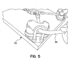
- Figure 5 shows the present invention in operation, in which the line is being pulled around the bail at an extreme angle.
- the line will not bind, and especially of the bail is constructed of stainless steel or other material having a smooth surface, such as stainless steel rod or the equivalent having a low friction bearing surface for the line.
Landscapes
- Chemical & Material Sciences (AREA)
- Engineering & Computer Science (AREA)
- Combustion & Propulsion (AREA)
- Mechanical Engineering (AREA)
- Ocean & Marine Engineering (AREA)
- Clamps And Clips (AREA)
- Hooks, Suction Cups, And Attachment By Adhesive Means (AREA)
Abstract
Description
- In general, a "fairlead" is a device used on a sailing vessel to lead and position the running rigging, for example, the lines which are used to control the position and shape of a sail. Fairleads are employed, to prevent excessive binding, friction, and/or chafe on the line that controls the running rigging.
- A "cam cleat" is a device widely used on sailing crafts, as well as in other applications requiring a releasable stop. The device generally comprises a base and a pair of cam-shaped toothed jaws or pawls pivotally mounted on the base and movable toward and away from each other, which provides a spacing between the jaws that is variable relative to the center line of the pawls to receive a downward and rearward pulling of the line by the free end to insert the line between the pawls in a locking relationship. The jaws have inwardly facing serrated surfaces and are spring loaded toward a closed position, such that a portion of line inserted from the top of the pawls will be secured toward a closed position. To release the line, the line is pulled up and out of engagement with the pawls. One type of cam cleat currently on the market is described in
U.S. Patent No. 4,453,486 , incorporated herein by reference. The pawls rotate around a fixed axis and bearing means, such as a sleeve, ball bearings or roller bearings may be provided to reduce internal friction and to improve performance in terms of insertion and removal of the line in a cleating and uncleating operation. - A cam cleat fairlead currently on the market and sold by Harken, Inc. of Pewaukee, Wisconsin, is shown in
Figure 1 . Fairleads such as these may be used at the entry or the exit of the cam cleat to allow the line to maintain alignment between the center line between the pawls of the cleat when the line is disengaged and then engaged again. If the line is not brought into alignment with the pawls, the cam cleat will not operate. - As generally shown in
Figure 1 , the prior art conventional assembly comprises a pair of jaws orpawls base 14. The fairlead comprises a strap, generally shown at 16, mounted above the cam cleat and this strap is designed to retain aline 18 between the jaws orpawls strap 16 includes an upper generally V-shaped notch 20, extending on an angle to vertical, with a pair of spaced vertical bearing tubes orelements Figure 1 , the line tends to become blocked or hung up by the upper part ofnotch 20, thus preventing reengagement of the line. This lessens versatility of the cleat and fairlead assembly in terms of where it can be positioned on the sailing vessel in an operative position, and also imposes constraints on the position of the person attempting to cleat the line, since the person may be moving to different positions on the sailing vessel and pulling on the line at an extreme angle. - "Harken Yacht Equipment 95", Harken Yacht Equipment Catalog, 1995 shows a cam fairlead.
- The present invention provides a cam cleat and fairlead assembly as set out in claim 1. The fairlead has improvements to allow engagement of the line into the cleat, in situations where the free end of the line being hauled at an angle of more than 45 and preferably more than 90 degrees relative to the centerline between the pawls of the cleat.
- The assembly of the present invention comprises a base unit or member for mounting a cam cleat as well as a fairlead near the exit of the cleat. The fairlead comprises a top and an inverted U-shaped tubular or, in some embodiments outside the scope of the present invention, inwardly facing curved member mounted in a fixed position between the top and the base. The inverted U-member or bail extends above the top of the pawls of the cleat to allow the line to be released. Also, the legs of the U-shaped member, which are secured from the base generally vertically and parallel to the top, have a width which is only slightly larger than the largest diameter line that the cam cleat can accept. It will be understood that cam cleats are provided in different sizes and have published specifications of the largest diameter line the cleat will accept. For example, the cleat might be designed to accept a line having a range of diameters of, for example, 3-10 millimeters, so the spacing between the legs of the fairlead would be in excess of 10 millimeters, for example, 11-14 millinieters. The spacing in the upper loop of the bail or inverted U-shaped member would provide even additional clearance to allow release of the line when released from the cleat.
- The assembly of fairlead/cam cleat greatly improves the versatility of the assembly in comparison with the prior art, especially in terms of allowing the person or sailor to engage the cleat at extreme angles regardless of the person or sailor. Also, due to the extreme angle engagement feature, the position or location of the cam and fairlead assembly is versatile and is not limited by prior art constraints.
-
-
Figure 1 is a perspective view showing a prior art cam cleat and fairlead combination. -
Figure 2 is a top view of the cam cleat and fairlead assembly of the present invention. -
Figure 3 is a rear end view of the assembly shown inFigure 2 . -
Figure 4 is a side view of the assembly shown inFigures 2 and 3 . -
Figure 5 is a perspective view of the combination shown inFigures 2-4 , additionally illustrating entry of a line, through the fairlead. -
Figures 2, 3, 4 and5 illustrate elements of the present invention and the combination of elements and the assembly. As shown, the assembly comprises abase unit 50 which is capable to be secured to a fixed part of a sailing vessel, such as a deck or mast (not show). Thebase 50 may contain recesses or adaptations to facilitate installation of a conventional cam cleat, generally shown at 52. Preferably, thebase 50 also includes a portion for supporting the fairlead, of the present invention, which is generally indicated at 54. Thecam cleat 52 and the fairlead 54 may be separately mounted, with the proviso that the alignment shown in the drawings generally prevails. - The
cam cleat 52 is conventional in nature, having a pair of opposed spring loadedpawls 56 rotatable aboutrespective posts 58, providing an open and closed position about acenterline 60. The cleat has anentrance side 62 in which the pawls are spaced, and anexit side 64 in which the pawls are narrowly spaced or closed. Aline 66 is pulled rearwardly and downwardly from theentrance 62 toward theexit 64 along thecenterline 60 to secure the line from forces toward or against the entrance. The line is released by upward tugging out of engagement with the pawls. - The
fairlead 54 comprises a top orcap portion 68, which, as shown, has a pair ofportions 70 with vertical apertures for securement by a threadedfastener 72 through the pivot axis of each pawl and into or through the base for securement, as a unitized assembly. The cap ortop 68 forms an enclosure above and around the cam cleat. - At the rear end of the
top 68, an inverted U-shapedmember 74 having substantially parallelvertical legs base 50 to thetop unit 68, with the top unit preferably covering themember 74 to prevent snagging by extraneous lines or interference with other objects. Thus, the upper portion ofmember 74, namely, theloop 76 portion, as shown, may be received in arecess 78 in thetop 68. - The dimensions of the inverted U-shaped member or
bail 74 is very important to the present invention. As discussed hereinbefore, all cam cleats are designed to accept, secure, and release lines having a specified range of diameters. A large size cleat, for example, will not adequately grip lines of fine diameter. Most importantly, for the purposes of the present invention, the maximum diameter of line that the cam cleat can accommodate is important. - With regard to the inverted U-shaped member or bail, the overall inner dimensions should be slightly larger than the maximum diameter of line than the cam cleat will accept. The maximum diameter of line is determined not only by the size of the cam cleat, but also by the maximum size of the pawls of the cleat when in a fully open or receiving position. The cleats have internal stops which absolutely prevent outer or separation rotation for accepting a line, and if this limit is exceeded, the cleat is inoperable.
-
Figure 5 shows the present invention in operation, in which the line is being pulled around the bail at an extreme angle. The line will not bind, and especially of the bail is constructed of stainless steel or other material having a smooth surface, such as stainless steel rod or the equivalent having a low friction bearing surface for the line.
Claims (11)
- A cam cleat and fairlead assembly for receiving a line having a free end, said assembly comprising a cam cleat (52) having a center line (60) of a forward engagement and free line disengagement portions, and a maximum diameter of a line acceptable for engagement, and a fairlead (54) associated with the said cam cleat (52) spaced behind said disengagement portion for holding said line in approximate alignment with the center line of the cam cleat (52), characterised in that said fairlead (54) comprises an inverted U-shaped member (74) having dimensions to cleat and uncleat the line, said U-shaped member comprising two substantially parallel legs (73, 75) and a loop portion (76) in the same plane, wherein the forward engagement and free line disengagement portions comprise pawls (56), and wherein the fairlead (54) is arranged to allow engagement of the line into the cleat in situations where the free end of the line is being hauled at an angle of more than 45° relative to the centreline between the pawls of the cleat.
- The assembly of Claim 1, wherein said dimensions are larger than the maximum diameter of the line engageable by the cam cleat (52).
- The assembly of Claim 1, wherein the assembly comprises a base (50) for securement to a support.
- The assembly of Claim 1, wherein said inverted U-shaped member has two substantially parallel legs (73, 75) and a loop portion (76) said legs and said loop portion all being at an exit side at which the pawls are spaced or closed.
- The assembly as in Claim 4, wherein said loop (76) comprises an upper portion of the U-shaped member and is spaced relatively to said one side of said cam cleat (52).
- The assembly as in Claim 5, further comprising a cap portion (68) extending from said loop portion (76) to relatively above said cam cleat (52).
- The assembly as in Claim 6, wherein said cap portion (68) is secured to said cam cleat (52).
- The assembly as in Claim 1, wherein said fairlead (54) has dimensions permitting said free end of said line to be hauled at an angle of more than 90° to the center line of said cam cleat (52) and released from said cam cleat but yet permit the line to be re-engaged with said cam cleat.
- The assembly as in Claim 1, wherein said inverted U-shaped member (74) is generally perpendicular to said center line.
- The assembly as in Claim 1, wherein said U-shaped member (74) has two legs (73, 75) and a top relatively above and connecting the two legs, the top being located relatively above and relatively in front of the hand side of the cam cleat.
- The assembly of Claim 1, wherein said plane is generally perpendicular to said center line.
Applications Claiming Priority (3)
| Application Number | Priority Date | Filing Date | Title |
|---|---|---|---|
| US224180 | 1998-12-31 | ||
| US10/224,180 US6722303B2 (en) | 2002-08-20 | 2002-08-20 | Fairlead and cam assembly |
| PCT/US2003/023024 WO2004019127A1 (en) | 2002-08-20 | 2003-07-23 | Fairlead and cam assembly |
Publications (3)
| Publication Number | Publication Date |
|---|---|
| EP1540415A1 EP1540415A1 (en) | 2005-06-15 |
| EP1540415A4 EP1540415A4 (en) | 2008-08-13 |
| EP1540415B1 true EP1540415B1 (en) | 2012-05-30 |
Family
ID=31886769
Family Applications (1)
| Application Number | Title | Priority Date | Filing Date |
|---|---|---|---|
| EP03792985A Expired - Lifetime EP1540415B1 (en) | 2002-08-20 | 2003-07-23 | Fairlead and cam assembly |
Country Status (4)
| Country | Link |
|---|---|
| US (1) | US6722303B2 (en) |
| EP (1) | EP1540415B1 (en) |
| AU (1) | AU2003261226B2 (en) |
| WO (1) | WO2004019127A1 (en) |
Families Citing this family (16)
| Publication number | Priority date | Publication date | Assignee | Title |
|---|---|---|---|---|
| US20040201005A1 (en) * | 1997-12-03 | 2004-10-14 | Peter Stone | Fail-safe device for raising/lowering articles |
| US7234686B2 (en) * | 1997-12-03 | 2007-06-26 | Peter Stone | Fail-safe cleat with automatic in-line locking cam and quick-release slot |
| US7073780B2 (en) * | 1997-12-03 | 2006-07-11 | Peter Stone | Fail-safe cleat with automatic in-line locking cam |
| US7226043B2 (en) * | 1997-12-03 | 2007-06-05 | Peter Stone | Stable fail-safe cleat with automatic in-line locking cam |
| GB2419916A (en) * | 2004-11-04 | 2006-05-10 | Clamcleats Ltd | Cleat assembly including a V-shaped groove having ridged grip walls wherein entry of an elongate member to the grip walls is controlled by a gate member(s) |
| GB2431907B (en) * | 2005-11-02 | 2009-04-15 | Balfour Beatty Plc | Device for use in lowering loads |
| US7287304B2 (en) * | 2005-12-20 | 2007-10-30 | Zebe Jr Charles W | Cam cleat construction |
| US7475867B1 (en) | 2007-09-07 | 2009-01-13 | Safeworks, Llc | Fairleads for building platforms |
| IT1403897B1 (en) * | 2010-12-30 | 2013-11-08 | Nube S R L | CRAFT FOR NAUTICAL USE |
| US9021974B1 (en) * | 2011-03-01 | 2015-05-05 | Wing Systems Associates, Ltd. | Cleat deck |
| US8438774B2 (en) | 2011-08-04 | 2013-05-14 | Lawrence C. Sharp | Pistol cocking assistive device |
| CN103466489B (en) * | 2013-09-24 | 2015-11-11 | 捷胜海洋装备股份有限公司 | One send rope device |
| US10274272B1 (en) * | 2018-08-30 | 2019-04-30 | Mark A. Owensby | Firearm slide assist deviceoma 4260 |
| US11591048B1 (en) * | 2021-02-11 | 2023-02-28 | Hotwire Development, Llc | Block and tackle assembly for bladder anchor |
| US12576948B1 (en) * | 2021-02-11 | 2026-03-17 | Hotwire Development, Llc | Block and tackle assembly for bladder anchor |
| CN114802596B (en) * | 2022-04-25 | 2023-06-13 | 武汉船用机械有限责任公司 | Modularized cable guide capable of automatically adjusting position and angle of guide wheel |
Family Cites Families (4)
| Publication number | Priority date | Publication date | Assignee | Title |
|---|---|---|---|---|
| US3815538A (en) * | 1973-05-04 | 1974-06-11 | D Jurgich | Cam cleat releasing mechanism |
| US4620499A (en) * | 1982-04-01 | 1986-11-04 | Slemmons Arthur J | Cam cleat |
| US5467726A (en) * | 1994-12-16 | 1995-11-21 | Hutchins; William L. | Furling line tension control for roller-reefing drum |
| GB2354992A (en) * | 1999-10-07 | 2001-04-11 | Phillip Anthony Cross | Lifting submerged weights |
-
2002
- 2002-08-20 US US10/224,180 patent/US6722303B2/en not_active Expired - Fee Related
-
2003
- 2003-07-23 AU AU2003261226A patent/AU2003261226B2/en not_active Ceased
- 2003-07-23 WO PCT/US2003/023024 patent/WO2004019127A1/en not_active Ceased
- 2003-07-23 EP EP03792985A patent/EP1540415B1/en not_active Expired - Lifetime
Also Published As
| Publication number | Publication date |
|---|---|
| US6722303B2 (en) | 2004-04-20 |
| EP1540415A1 (en) | 2005-06-15 |
| EP1540415A4 (en) | 2008-08-13 |
| AU2003261226B2 (en) | 2008-12-18 |
| AU2003261226A1 (en) | 2004-03-11 |
| US20040035348A1 (en) | 2004-02-26 |
| WO2004019127A1 (en) | 2004-03-04 |
Similar Documents
| Publication | Publication Date | Title |
|---|---|---|
| US6722303B2 (en) | Fairlead and cam assembly | |
| US6685171B2 (en) | Lifting device | |
| US4465011A (en) | Halyard stopper | |
| US20160107728A1 (en) | Threadless fairlead | |
| US4217847A (en) | Self-release cam cleat | |
| US7712804B2 (en) | Method and apparatus for controlling a rope | |
| US8245360B2 (en) | Rope grip slip-knot device | |
| US4092941A (en) | Adjustable two-way cam cleat | |
| US10859134B2 (en) | Rope gripper | |
| CN223280395U (en) | Rope restraining device and rope tensioning device | |
| US4458617A (en) | Board sailing harness | |
| US12351274B2 (en) | Strut actuated bimini top | |
| AU766212B2 (en) | Swivel post latch system for bearing block | |
| US6634311B2 (en) | Apparatus and method for guiding and hoisting a sail | |
| US4241684A (en) | Tiller steering lock | |
| US7104213B2 (en) | Hawser guidance system for quick release mooring hooks | |
| WO2016183658A1 (en) | Sail slugs and their use in a downhaul system | |
| CA2535595C (en) | Anchor rope lock | |
| CA2032608C (en) | Line laying device and operating method | |
| WO2013081465A1 (en) | Sliding wedge cleat for a large diameter fibre rope | |
| AU780282B2 (en) | Boom vang for sailing vessel | |
| US4096607A (en) | Snap fastening device | |
| US5115755A (en) | Quick attachment release jib handling and stowage system | |
| US20090072208A1 (en) | Device for Guiding the Bolt Rope of a Sail | |
| EP2190732B1 (en) | Device for a sailing boat |
Legal Events
| Date | Code | Title | Description |
|---|---|---|---|
| PUAI | Public reference made under article 153(3) epc to a published international application that has entered the european phase |
Free format text: ORIGINAL CODE: 0009012 |
|
| 17P | Request for examination filed |
Effective date: 20050311 |
|
| AK | Designated contracting states |
Kind code of ref document: A1 Designated state(s): AT BE BG CH CY CZ DE DK EE ES FI FR GB GR HU IE IT LI LU MC NL PT RO SE SI SK TR |
|
| AX | Request for extension of the european patent |
Extension state: AL LT LV MK |
|
| DAX | Request for extension of the european patent (deleted) | ||
| RBV | Designated contracting states (corrected) |
Designated state(s): DE FR GB IT |
|
| A4 | Supplementary search report drawn up and despatched |
Effective date: 20080716 |
|
| RIC1 | Information provided on ipc code assigned before grant |
Ipc: B63B 21/08 20060101ALI20080710BHEP Ipc: G03C 1/825 20060101ALI20080710BHEP Ipc: G03C 1/498 20060101ALI20080710BHEP Ipc: B63B 21/10 20060101ALI20080710BHEP Ipc: G03C 1/34 20060101AFI20040317BHEP |
|
| 17Q | First examination report despatched |
Effective date: 20100816 |
|
| GRAP | Despatch of communication of intention to grant a patent |
Free format text: ORIGINAL CODE: EPIDOSNIGR1 |
|
| GRAS | Grant fee paid |
Free format text: ORIGINAL CODE: EPIDOSNIGR3 |
|
| GRAA | (expected) grant |
Free format text: ORIGINAL CODE: 0009210 |
|
| AK | Designated contracting states |
Kind code of ref document: B1 Designated state(s): DE FR GB IT |
|
| REG | Reference to a national code |
Ref country code: GB Ref legal event code: FG4D |
|
| REG | Reference to a national code |
Ref country code: DE Ref legal event code: R096 Ref document number: 60341109 Country of ref document: DE Effective date: 20120726 |
|
| PG25 | Lapsed in a contracting state [announced via postgrant information from national office to epo] |
Ref country code: IT Free format text: LAPSE BECAUSE OF FAILURE TO SUBMIT A TRANSLATION OF THE DESCRIPTION OR TO PAY THE FEE WITHIN THE PRESCRIBED TIME-LIMIT Effective date: 20120530 |
|
| PLBE | No opposition filed within time limit |
Free format text: ORIGINAL CODE: 0009261 |
|
| STAA | Information on the status of an ep patent application or granted ep patent |
Free format text: STATUS: NO OPPOSITION FILED WITHIN TIME LIMIT |
|
| GBPC | Gb: european patent ceased through non-payment of renewal fee |
Effective date: 20120830 |
|
| REG | Reference to a national code |
Ref country code: FR Ref legal event code: ST Effective date: 20130329 |
|
| PG25 | Lapsed in a contracting state [announced via postgrant information from national office to epo] |
Ref country code: FR Free format text: LAPSE BECAUSE OF NON-PAYMENT OF DUE FEES Effective date: 20120731 Ref country code: DE Free format text: LAPSE BECAUSE OF NON-PAYMENT OF DUE FEES Effective date: 20130201 |
|
| 26N | No opposition filed |
Effective date: 20130301 |
|
| PG25 | Lapsed in a contracting state [announced via postgrant information from national office to epo] |
Ref country code: GB Free format text: LAPSE BECAUSE OF NON-PAYMENT OF DUE FEES Effective date: 20120830 |
|
| REG | Reference to a national code |
Ref country code: DE Ref legal event code: R119 Ref document number: 60341109 Country of ref document: DE Effective date: 20130201 |