EP1539014B1 - Sliding seal adapter for a feeding system - Google Patents
Sliding seal adapter for a feeding system Download PDFInfo
- Publication number
- EP1539014B1 EP1539014B1 EP02766051A EP02766051A EP1539014B1 EP 1539014 B1 EP1539014 B1 EP 1539014B1 EP 02766051 A EP02766051 A EP 02766051A EP 02766051 A EP02766051 A EP 02766051A EP 1539014 B1 EP1539014 B1 EP 1539014B1
- Authority
- EP
- European Patent Office
- Prior art keywords
- spike
- adapter
- sliding shaft
- shaft seal
- conduit
- Prior art date
- Legal status (The legal status is an assumption and is not a legal conclusion. Google has not performed a legal analysis and makes no representation as to the accuracy of the status listed.)
- Expired - Lifetime
Links
- 239000012530 fluid Substances 0.000 claims abstract description 62
- 239000011888 foil Substances 0.000 claims description 10
- 238000007789 sealing Methods 0.000 claims description 6
- 239000012528 membrane Substances 0.000 claims description 5
- 238000000034 method Methods 0.000 claims 7
- 230000000149 penetrating effect Effects 0.000 claims 1
- 235000016709 nutrition Nutrition 0.000 description 10
- 230000035764 nutrition Effects 0.000 description 9
- 230000014759 maintenance of location Effects 0.000 description 8
- 238000011109 contamination Methods 0.000 description 5
- 239000007788 liquid Substances 0.000 description 4
- 239000000463 material Substances 0.000 description 4
- 239000000356 contaminant Substances 0.000 description 3
- 210000005224 forefinger Anatomy 0.000 description 2
- 238000005096 rolling process Methods 0.000 description 2
- 210000003813 thumb Anatomy 0.000 description 2
- 239000004820 Pressure-sensitive adhesive Substances 0.000 description 1
- 239000000853 adhesive Substances 0.000 description 1
- 230000007812 deficiency Effects 0.000 description 1
- 230000000994 depressogenic effect Effects 0.000 description 1
- 239000003814 drug Substances 0.000 description 1
- 229940079593 drug Drugs 0.000 description 1
- 239000013013 elastic material Substances 0.000 description 1
- 229920001971 elastomer Polymers 0.000 description 1
- 239000013536 elastomeric material Substances 0.000 description 1
- 230000007613 environmental effect Effects 0.000 description 1
- 230000036571 hydration Effects 0.000 description 1
- 238000006703 hydration reaction Methods 0.000 description 1
- 238000002347 injection Methods 0.000 description 1
- 239000007924 injection Substances 0.000 description 1
- 210000001630 jejunum Anatomy 0.000 description 1
- 239000000314 lubricant Substances 0.000 description 1
- 238000004519 manufacturing process Methods 0.000 description 1
- 230000013011 mating Effects 0.000 description 1
- 238000012986 modification Methods 0.000 description 1
- 230000004048 modification Effects 0.000 description 1
- 210000004798 organs belonging to the digestive system Anatomy 0.000 description 1
- 230000002093 peripheral effect Effects 0.000 description 1
- 230000002028 premature Effects 0.000 description 1
- 210000002784 stomach Anatomy 0.000 description 1
- 229920001169 thermoplastic Polymers 0.000 description 1
- 229920002725 thermoplastic elastomer Polymers 0.000 description 1
- 229920001187 thermosetting polymer Polymers 0.000 description 1
- 239000004416 thermosoftening plastic Substances 0.000 description 1
- 210000003462 vein Anatomy 0.000 description 1
Images




Classifications
-
- A—HUMAN NECESSITIES
- A61—MEDICAL OR VETERINARY SCIENCE; HYGIENE
- A61J—CONTAINERS SPECIALLY ADAPTED FOR MEDICAL OR PHARMACEUTICAL PURPOSES; DEVICES OR METHODS SPECIALLY ADAPTED FOR BRINGING PHARMACEUTICAL PRODUCTS INTO PARTICULAR PHYSICAL OR ADMINISTERING FORMS; DEVICES FOR ADMINISTERING FOOD OR MEDICINES ORALLY; BABY COMFORTERS; DEVICES FOR RECEIVING SPITTLE
- A61J1/00—Containers specially adapted for medical or pharmaceutical purposes
- A61J1/05—Containers specially adapted for medical or pharmaceutical purposes for collecting, storing or administering blood, plasma or medical fluids ; Infusion or perfusion containers
- A61J1/10—Bag-type containers
-
- A—HUMAN NECESSITIES
- A61—MEDICAL OR VETERINARY SCIENCE; HYGIENE
- A61M—DEVICES FOR INTRODUCING MEDIA INTO, OR ONTO, THE BODY; DEVICES FOR TRANSDUCING BODY MEDIA OR FOR TAKING MEDIA FROM THE BODY; DEVICES FOR PRODUCING OR ENDING SLEEP OR STUPOR
- A61M5/00—Devices for bringing media into the body in a subcutaneous, intra-vascular or intramuscular way; Accessories therefor, e.g. filling or cleaning devices, arm-rests
- A61M5/14—Infusion devices, e.g. infusing by gravity; Blood infusion; Accessories therefor
- A61M5/162—Needle sets, i.e. connections by puncture between reservoir and tube ; Connections between reservoir and tube
-
- A—HUMAN NECESSITIES
- A61—MEDICAL OR VETERINARY SCIENCE; HYGIENE
- A61J—CONTAINERS SPECIALLY ADAPTED FOR MEDICAL OR PHARMACEUTICAL PURPOSES; DEVICES OR METHODS SPECIALLY ADAPTED FOR BRINGING PHARMACEUTICAL PRODUCTS INTO PARTICULAR PHYSICAL OR ADMINISTERING FORMS; DEVICES FOR ADMINISTERING FOOD OR MEDICINES ORALLY; BABY COMFORTERS; DEVICES FOR RECEIVING SPITTLE
- A61J1/00—Containers specially adapted for medical or pharmaceutical purposes
- A61J1/14—Details; Accessories therefor
- A61J1/1475—Inlet or outlet ports
-
- A—HUMAN NECESSITIES
- A61—MEDICAL OR VETERINARY SCIENCE; HYGIENE
- A61M—DEVICES FOR INTRODUCING MEDIA INTO, OR ONTO, THE BODY; DEVICES FOR TRANSDUCING BODY MEDIA OR FOR TAKING MEDIA FROM THE BODY; DEVICES FOR PRODUCING OR ENDING SLEEP OR STUPOR
- A61M39/00—Tubes, tube connectors, tube couplings, valves, access sites or the like, specially adapted for medical use
- A61M39/10—Tube connectors; Tube couplings
- A61M39/14—Tube connectors; Tube couplings for connecting tubes having sealed ends
-
- A—HUMAN NECESSITIES
- A61—MEDICAL OR VETERINARY SCIENCE; HYGIENE
- A61M—DEVICES FOR INTRODUCING MEDIA INTO, OR ONTO, THE BODY; DEVICES FOR TRANSDUCING BODY MEDIA OR FOR TAKING MEDIA FROM THE BODY; DEVICES FOR PRODUCING OR ENDING SLEEP OR STUPOR
- A61M5/00—Devices for bringing media into the body in a subcutaneous, intra-vascular or intramuscular way; Accessories therefor, e.g. filling or cleaning devices, arm-rests
- A61M5/14—Infusion devices, e.g. infusing by gravity; Blood infusion; Accessories therefor
- A61M5/162—Needle sets, i.e. connections by puncture between reservoir and tube ; Connections between reservoir and tube
- A61M5/1626—Needle protectors therefor
Definitions
- the adapter comprises a body member connected between a spike member and a locking collar.
- the body member includes a body portion having a generally cylindrical shape and an annular ring formed thereon with a plurality of protrusions which are longitudinally formed along the body member.
- a pair of leg portions axially extends from the body portion with retention tabs formed at the free end thereof for engaging the body member to the spike member.
- the adapter further comprises a sliding shaft seal positioned within the body member for providing a leak-free seal within the adapter during operation.
- the spike member is coupled to the body member and includes a spike body which is generally frusto-conical in shape with an opposed pair of slots formed longitudinally along the spike body which are sized and shaped to slidably receive corresponding protrusions formed along the body portion.
- An axial spike to penetrate the seal of the fluid container outwardly extends from the spike body and includes a longitudinal slot formed therealong which terminates at an angularly skewed pointed end.
- Two generally opposed openings are formed through the spike body and are sized and shaped to receive and securely retain a respective leg portion of the body member thereto. As a result, the spike member is slidably coupled with the body member.
- adapter 10 of the present invention also includes locking collar 16 comprising a body portion 62 with opposed openings 65, 66 forming a channel 64 therebetween.
- Channel 64 includes an annular groove 67 formed proximate opening 65 and a threaded portion 68 formed proximate opening 66.
- longitudinal grooves 70 are formed along the body portion 62 of the locking collar 16 to enhance the ability of the user to grasp the locking collar 16.
- one skilled in the art can best appreciate that a variety of other connective arrangements may be utilized without departing from the teachings of the present invention.
- This sealing engagement by the sliding shaft seal 18 is provided about spike 52 whether adapter (10) is actuated, i.e. during operation, or unactuated, i.e. when the spike 52 is in a free state with the spike 52 retracted.
- a lubricant can be applied along the spike 52 and/or conduit 77 for lowering the coefficient of friction between sliding shaft seal 18 and spike 52.
- Sliding shaft seal 18 further comprises a sealing flange 74 disposed proximate proximal opening 73 and circumferentially disposed about the body portion 72, while a locking flange 76 is formed proximate distal opening 75.
- adapter 10 is assembled during manufacturing by first inserting the sliding shaft seal 18 within body member 12 by placing distal end 75 of shaft seal 18 through opening 25. Sliding shaft seal 18 is then aligned within channel 31 such that the locking flange 76 crowns the ridge 23, while the sealing flange 74 abuts the opening 25 of body member 12 so that sliding shaft seal 18 is properly secured within body portion 20 of body member 12. Next, the locking collar 16 is then engaged about the body member 12 so that annular flange 34 of body member 12 is engagingly received within the annular groove 66 of locking collar 16.
- Spring 19 is placed between leg portions 26 of body member 12 such that distal opening 75 of sliding shaft seal 18 is properly aligned with opening 120 of Spring 19.
Landscapes
- Health & Medical Sciences (AREA)
- Life Sciences & Earth Sciences (AREA)
- Veterinary Medicine (AREA)
- Public Health (AREA)
- General Health & Medical Sciences (AREA)
- Animal Behavior & Ethology (AREA)
- Hematology (AREA)
- Heart & Thoracic Surgery (AREA)
- Anesthesiology (AREA)
- Engineering & Computer Science (AREA)
- Vascular Medicine (AREA)
- Pharmacology & Pharmacy (AREA)
- Biomedical Technology (AREA)
- Infusion, Injection, And Reservoir Apparatuses (AREA)
- Package Closures (AREA)
- Jet Pumps And Other Pumps (AREA)
- Medical Preparation Storing Or Oral Administration Devices (AREA)
- Automatic Assembly (AREA)
- Sealing Of Jars (AREA)
- Quick-Acting Or Multi-Walled Pipe Joints (AREA)
- Processing Of Terminals (AREA)
- Processing And Handling Of Plastics And Other Materials For Molding In General (AREA)
- Loading And Unloading Of Fuel Tanks Or Ships (AREA)
Abstract
Description
- The present invention generally relates to an adapter for interconnecting a fluid container with an administration feeding set, and more particularly to an adapter having a retractable spike for use with a feeding system.
- Feeding systems are frequently used to provide nutrition through either enteral or parenteral access to a patient unable to take nutrition orally. As used herein, the term nutrition shall be interpreted to include nutrition, medication and hydration. These feeding systems typically comprise an administration feeding set attached to a source of nutrition at one end and some kind of tube arrangement at the other end for providing nutrition immediately to a patient. In enteral feeding, the nutrition is typically administered to the patient by accessing a digestive organ through use of a nasogastric or gastrostomy tube which terminates in the stomach, or a nasojejunal or jejunostomy tube which terminates in the jejunum. In contrast, parenteral feeding typically includes feeding nutrition by injection into a vein. Such feeding systems also include fluid containers which hold nutritional fluid in liquid form and typically include an opening sealed with a flexible membrane to seal and isolate the contents from environmental contaminants.
- Often fluid containers of the above-mentioned character are connected to the administration feeding set by an adapter. One such adapter typical of the prior art is disclosed in
U.S. Patent No. 4,567,999 to Hjertman et al. entitled "Self-adhesive Connecting Device." Hjertman discloses an adapter for providing a sealed liquid connection with the orifice of a fluid container formed from a flexible sheet material. The adapter includes a hollow chamber with an outside surface adapted to be adhered to the container wall and a sharp point that is encased therein which is operative to penetrate the wall of the container. A pressure sensitive adhesive is provided on the outer peripheral surface of the Hjertman adapter that is intended to attach the adapter to the container wall such that the hollow chamber is sealed from outside contaminates. - Although the device of Hjertman et al. effectively provides a sealed liquid connection with a container, such devices also have several inherent drawbacks. Because the device to Hjertman entirely encloses the sharp point within the chamber, the user of these devices would need to apply a sufficiently strong exterior force to the chamber in order to actuate the device. However, directly exerting an exterior force upon the chamber to actuate the device increases the possibility of rupturing the chamber and resulting in mechanical failure of the device. Moreover, inadvertent impacts upon the chamber during transportation and storage are also likely to result in premature rupturing of the chamber. Finally, properly adhered to the container, such devices cannot be easily reused with other fluid containers.
- Other connection devices have been suggested to further advance the art. For instance,
U.S. Patent No. 5,041,105 to D'Alo et al. entitled "Vented Spike Connection Component," which is assigned to the assignee of the present invention, discloses a connection component suitable for use with a feeding system which includes a fluid container having a cap with an orifice and external threading disposed about the cap. A foil, or other similar frangible material, seals off the orifice of the container from fluid flow and outside contaminants. The connection component includes internal threading that mates with the external threading of the cap and a projecting spike which is adapted to penetrate the foil seal and establish fluid flow as the connection component is attached to the fluid container and actuated. - Although the D'Alo et al. device substantially advances the art, such connection components could still be further improved upon. The device to D'Alo et al. relies solely on frictional engagement between the threaded portion of the housing body and the threaded portion of the cap to create and maintain a fluid-tight seal. The device to D'Alo et al. also operates to simultaneously pierce the container when the user connects the connection component, and thus the operator must interconnect the device at the precise moment when it is desired to establish fluid flow. In other words, the operator cannot attach the D'Alo et al. device to the pre-filled container without instantaneously piercing the foil seal and establishing fluid flow which may be undesirable. Accordingly, the operator must delay attaching the device to the container until needed, or the operator must attach the device to the fluid container and immediately establish fluid flow when the foil seal is pierced by the device connection.
- Therefore, one skilled in the art can best appreciate that several advances would still be desirable. It would be desirable to have a connection device that may be properly secured to the container, while allowing the operator to delay piercing the fluid container and establish fluid flow when needed. It would also be desirable to have a connection device which provides a leak-free seal at all times between the fluid container, the connection device, and the administration feeding set. It would be further desirable to have a spike of the connection device which is shielded from touch contamination by the user.
-
U.S. Patent No. 6,183,465 to Meier et al. entitled "Adapter for a Feeding System," which is assigned to the assignee of the present invention discloses an arrangement of an adapter for a feeding system which includes a rolling seal diaphragm for establishing fluid flow communication between a nutrition container and an administration tubing while maintaining a fluid tight seal. The arrangement includes a spike and the rolling seal diaphragm sealingly engages the retractable spike and biases the spike in a disengaged position. - A primary object of the present invention is to provide an adapter which is capable of establishing fluid flow communication between a fluid container and an administration feeding set while maintaining a fluid-tight seal therebetween at all times.
- A further object of the present invention is to provide an adapter having a sliding shaft seal that maintains a fluid-tight seal around the axial spike during operation of the adapter.
- Another object of the present invention is to provide a connection device that allows the container to be sealingly connected to the administration feeding set without simultaneously piercing the flexible membrane of the fluid container.
- Another further object of the present invention is to provide an adapter having a retractable touch free spike that is shielded from touch contamination by the user.
- In brief summary, the present invention overcomes and substantially alleviates the deficiencies in the prior art by providing an adapter that includes a sliding shaft seal which provides a leak-free connection site and shields the shaft from contamination. The adapter operates as a connector between a fluid container and an administration feeding set with the fluid container having a cap that has an orifice and an external threading disposed about the cap. A foil, or other frangible membrane, seals off the orifice of the container from fluid flow prior to use. The administration feeding set includes hollow flexible tubing which interconnects a tube arrangement attached to a patient to the fluid container via the adapter of the present invention.
- The adapter comprises a body member connected between a spike member and a locking collar. The body member includes a body portion having a generally cylindrical shape and an annular ring formed thereon with a plurality of protrusions which are longitudinally formed along the body member. A pair of leg portions axially extends from the body portion with retention tabs formed at the free end thereof for engaging the body member to the spike member. The adapter further comprises a sliding shaft seal positioned within the body member for providing a leak-free seal within the adapter during operation.
- The spike member is coupled to the body member and includes a spike body which is generally frusto-conical in shape with an opposed pair of slots formed longitudinally along the spike body which are sized and shaped to slidably receive corresponding protrusions formed along the body portion. An axial spike to penetrate the seal of the fluid container outwardly extends from the spike body and includes a longitudinal slot formed therealong which terminates at an angularly skewed pointed end. Two generally opposed openings are formed through the spike body and are sized and shaped to receive and securely retain a respective leg portion of the body member thereto. As a result, the spike member is slidably coupled with the body member. The spike member also includes a tube adapter at its proximal end which axially extends therefrom and is adapted to attach the adapter of the present invention to the administration feeding set. A coiled spring is provided to apply a spring force against the spike member for actuating and biasing the adapter during operation thereof.
- The locking collar is coupled to the body member and has a hollow cylindrical shape forming a channel with opposed openings. An annular groove is formed adjacent one of the openings and is sized and shaped to be engaged by the annular ring formed around the body member such that the locking collar is engaged to the body member, but rotates freely thereabout. The locking collar also includes an internal threaded portion defined about the channel proximate the other opposed opening for mating engagement with the external threaded portion of the fluid container when the adapter is attached thereto.
- One unique aspect of the present invention is that it includes a sliding shaft seal disposed at least partially within the body member and around the axial spike. The sliding shaft seal includes a hollow, flexible body defining a conduit formed between opposed proximal and distal ends which define respective openings. The sliding shaft seal further includes a sealing flange formed proximate the proximal opening, while a locking flange is formed proximate the distal opening. In assembly, the sliding shaft seal is disposed within the body member such that the shaft of the spike is sealingly surrounded by the conduit of the sliding shaft seal. The spring is co-axially aligned with and engaged to the sliding shaft seal for applying a spring force against the spike body during operation.
- In operation, the operator of the present invention may easily and securely connect the adapter between the fluid container and the administration feeding set by first threading the threaded portion of the locking collar onto the threaded portion of the cap while the spike is isolated within the locking collar from inadvertent contact with outside contaminants which may result in contamination of the spike. It will be appreciated that, although the adapter is secured to the container, the spike does not simultaneously pierce and breach the foil that seals off the orifice of the fluid container until actuated by the user. Once the locking collar is properly secured, the administration feeding set is connected between the patient's tube arrangement and the adapter, while the spike member is maintained in the disengaged position. The operator will then grasp the spike body between the thumb and forefinger and move the spike member axially forward relative to the body member and against the spring force applied by the spring so that the spike extends forward through the locking collar and is driven through the foil of the fluid container, thereby establishing fluid flow through the spike. After the foil has been breached and fluid flow established, the operator will then release the spike member which will then be biased back within the locking collar by the spring force applied by the spring. During operation of the adapter, the sliding shaft seal maintains a fluid tight seal about the axial spike as the spike is moved longitudinally during actuation. When fluid flow communication is established with the fluid container the sliding shaft seal continues to maintain a fluid tight seal around the spike, while preventing the user to touch and contaminate the spike during operation.
- These and other objects of the present invention are realized in the preferred embodiment of the present invention, described by way of example and not by way of limitation, which provides for an adapter having a retractable spike including a sliding shaft seal for establishing leak-free fluid flow communication along the spike.
- Additional objects, advantages and novel features of the invention will be set forth in the description which follows, and will become apparent to those skilled in the art upon examination of the following more detailed description and drawings in which like elements of the invention are similarly numbered throughout.
-
-
Figure 1 is a cross-sectional view of a preferred embodiment of the adapter connected between a fluid container and an administration feeding set according to the present invention; -
Figure 2 is a perspective view of a preferred embodiment of the adapter according to the present invention; -
Figure 3 is an exploded perspective view of the preferred embodiment of the adapter according to the present invention; -
Figure 4a is a side elevational view of the preferred embodiment of the adapter in an unactuated position according to the present invention; -
Figure 4b is a side elevational view of an alternative embodiment of the adapter in an unactuated position according to the present invention; -
Figure 5 is a top plan view of the preferred embodiment of the adapter in an unactuated position according to the present invention; -
Figure 6 is a cross-sectional view of the preferred embodiment of the adapter shown along line 6-6 ofFigure 4a according to the present invention; -
Figure 7 is a cross-sectional of the preferred embodiment of the adapter shown along line 7-7 ofFigure 5 according to the present invention; -
Figure 8 is a top plan view of the preferred embodiment of the adapter in an actuated position according to the present invention; -
Figure 9 is a side elevational view of the preferred embodiment of the adapter in an actuated position according to the present invention; -
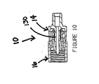
Figure 10 is a cross-sectional view of the preferred embodiment of the adapter shown along line 10-10 ofFigure 8 according to the present invention; and -
Figure 11 is a cross-sectional view of the preferred embodiment of the adapter shown along line 11-11 ofFigure 9 according to the present invention. - Referring to the drawings, the preferred embodiment of the adapter for a feeding system 9 of the present invention is illustrated and generally indicated as 10 in
FIG. 1 . As shown,adapter 10 operates as a connector between afluid container 88 and an administration feeding set 90 with thefluid container 88 including a cap 92 that has anorifice 96 and threading 98 formed about the cap 92. Afoil 100, or other frangible membrane, seals off theorifice 96 ofcontainer 88 from fluid flow. The administration feeding set 90 includestubing 94 which interconnects a tube arrangement (not shown) which is connected to thefluid container 88 via theadapter 10 of the present invention. Referring toFIG. 2 , theadapter 10 comprises abody member 12 slidably connected to abiased spike member 14 and rotatably connected to alocking collar 16. In addition, as shown inFIG. 3 ,adapter 10 further includes a slidingshaft seal 18 disposed within thebody member 12 for providing a fluid tight seal between theadapter 10 andfluid container 88. - As further shown,
body member 12 comprises a hollow body portion 20 having opposedopenings channel 31 therebetween with a pair of laterallyopposed leg portions 26 which extend axially proximate theopening 27. Preferably,body member 12 has a pair ofleg portions 26, although in the alternative, one skilled in the art can best appreciate that any suitable number ofleg portions 26 may be utilized without departing from the teachings of the present invention. Eachleg portion 26 includes atab 22 formed at the free end thereof. Preferably,tabs 22 are bifurcated along the free end thereof. - The
body member 12 further includes an interiorannular ridge 23 formedadjacent opening 27 and two pairs of opposedprotrusions 28 longitudinally aligned and extending along the body portion 20. Formed between each pair ofprotrusions 28 is abeveled portion 30 defining aledge 32. Further,body member 12 includes an exteriorannular flange 34 formedproximate opening 25. Alternatively, it should be appreciated that any suitable number ofprotrusions 28 may be utilized. - As seen in
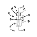
FIGS. 3 ,4a, and 4b ,spike member 14 ofadapter 10 comprises aspike body 42 defining two opposed pairs oflongitudinal slots 44 which are adapted to correspond to the two opposed pairs ofprotrusions 28 formed onbody member 12. Eachslot 44 is sized and shaped to slidably receive a correspondingprotrusion 28 when thespike member 14 is in the actuated position, as shall be discussed in greater detail below. In addition,spike member 14 further includes twoaxial openings 43, as particularly shown inFIG. 3 , which are sized and shaped to receive and retain acorresponding tab 22 of eachleg portion 26 when inserted therethrough. Alternatively, one skilled in the art can appreciate that any number ofslots 44 andopenings 43 may be utilized to interconnect thebody member 12 to spikemember 14 without departing from the teachings of the present invention. - With reference to
FIGS. 4a, 4b , and6 , each pair ofslots 44 defines aretention section 46 which includes aretention edge 48 formed at a distal or free end of eachsection 46. Eachretention section 46 is positioned between a respective corresponding pair ofprotrusions 28 and is adapted to slide between each pair ofprotrusions 28 while traveling along the correspondingbeveled portion 30 formed along thebody member 12. During the aforementioned sliding action, theretention section 46 is prevented from separating frombody member 12 due to the engagement betweenretention edge 48 ofspike member 14 and theledge 32 formed alongbody member 12 as well as the relative action oftab 22 withspike body 42, as shall be described in greater detail later. - As best appreciated in
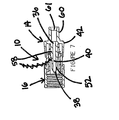
FIG. 7 ,spike member 14 further includes a hollowaxial spike 52 outwardly extending from thespike body 42 defining opposed ends 36, 38 which form achannel 40 therebetween. With particular reference toFIG. 3 , spike 52 includes a distal longitudinal slot 56 formed along a portion ofspike 52 and that terminates at an angularlyskewed end 54 for receiving fluid flow therethrough. Referring back toFIG. 7 , circumferentially disposed about thespike 52 is ashoulder portion 58 which assists in forming a seal between thespike member 14 and slidingshaft seal 18.Spike body 42 further includes aproximal tube adapter 60 formedopposite spike 52 which is bonded to administration feeding set 90.Spike 52 has anopening 61 in communication withslot 52 and co-axially aligned withspike 52proximate end 36 which is sized and shaped to be bonded to administration feeding set 90, as illustrated inFIG. 1 . As further shown, a spring 19 having anopening 120 is provided for applying a spring force againstspike member 14 during operation ofadapter 10. Preferably, spike 52 is disposed entirely within theadapter 10 as illustrated inFIG. 4a . In an alternative embodiment shown inFIG. 4b , spike 52 extends beyond thecollar 16 whenadapter 10 is fully assembled. - Referring to
FIGS. 2 ,3 and6 ,adapter 10 of the present invention also includes lockingcollar 16 comprising abody portion 62 withopposed openings channel 64 therebetween.Channel 64 includes anannular groove 67 formedproximate opening 65 and a threadedportion 68 formedproximate opening 66. As seen in the preferred embodiment shown inFIG. 4a ,longitudinal grooves 70 are formed along thebody portion 62 of the lockingcollar 16 to enhance the ability of the user to grasp the lockingcollar 16. However, one skilled in the art can best appreciate that a variety of other connective arrangements may be utilized without departing from the teachings of the present invention. - As illustrated in
FIG. 3 , one unique aspect ofadapter 10 is that it includes slidingshaft seal 18 which forms and maintains a fluid-tight seal aroundaxial spike 52 during operation ofadapter 10. With reference toFIGS. 3 and10 , slidingshaft seal 18 comprises abody portion 72 which includes a pair of opposed proximal anddistal openings conduit 77 formed therebetween.Conduit 77 is sized and shaped to provide a sealing engagement withspike 52 along a small percentage of the length ofconduit 77 at any one time. As illustrated inFIG. 6 , an O-ring portion 125 is preferably molded toconduit 77 at a strategic location therealong for providing the sliding seal engagement withspike 52. This sealing engagement by the slidingshaft seal 18 is provided aboutspike 52 whether adapter (10) is actuated, i.e. during operation, or unactuated, i.e. when thespike 52 is in a free state with thespike 52 retracted. A lubricant can be applied along thespike 52 and/orconduit 77 for lowering the coefficient of friction between slidingshaft seal 18 andspike 52. Slidingshaft seal 18 further comprises a sealingflange 74 disposed proximateproximal opening 73 and circumferentially disposed about thebody portion 72, while a locking flange 76 is formed proximatedistal opening 75. - With particular reference to
FIG. 3 ,adapter 10 is assembled during manufacturing by first inserting the slidingshaft seal 18 withinbody member 12 by placingdistal end 75 ofshaft seal 18 throughopening 25. Slidingshaft seal 18 is then aligned withinchannel 31 such that the locking flange 76 crowns theridge 23, while the sealingflange 74 abuts theopening 25 ofbody member 12 so that slidingshaft seal 18 is properly secured within body portion 20 ofbody member 12. Next, the lockingcollar 16 is then engaged about thebody member 12 so thatannular flange 34 ofbody member 12 is engagingly received within theannular groove 66 of lockingcollar 16. Spring 19 is placed betweenleg portions 26 ofbody member 12 such thatdistal opening 75 of slidingshaft seal 18 is properly aligned with opening 120 of Spring 19. Thespike 52 ofspike body 42 is then inserted through therespective openings shaft seal 18 respectively such thattabs 22 on eachleg portion 26 are inserted through thelongitudinal slots 44 ofspike body 42.Spike member 14 is then connected tobody member 12 and aligned so that eachprotrusion 28 is slidably received within each correspondingslot 44 ofspike body 42.Spike member 14 is then axially depressed ontobody member 12 untiltabs 22 are passed through the correspondingopenings 43 andretention edge 48 is disposed adjacent thebeveled portion 30. Once so assembled,spike member 14 may be biased between two positions by the user: an actuated position, whereinspike member 14 abuts lockingcollar 16, as illustrated inFIGS. 10 and11 , and an unactuated position, whereinspike member 14 abutstabs 22 of thebody member 12, as seen inFIGS. 4a and5 . - In operation, the
adapter 10 of the present invention is uniquely configured to interconnect thefluid container 88 to the administration feeding set 90. As seen inFIG. 1 , theadapter 10 is connected to thefluid container 88 by screwing the threadedportion 68 of the lockingcollar 16 onto the threadedportion 98 of the cap 92 while thespike 52 is isolated within thecollar 16 by slidingshaft seal 18 to prevent undesirable contact and contamination of theaxial spike 52. When it is desirable to actuateadapter 10 and establish fluid flow, the user will graspspike member 14, preferably between the operator 's thumb and forefinger (not shown), and urge thespike member 14 forwardly to the actuated position illustrated inFIGS. 8 and9 , throughcollar 16. With particular reference toFIGS. 10 and11 , the forward axial motion ofspike 52 is restrained at one point by the abutment ofretention edge 48 ofspike member 14 withcollar 16 and the spring force applied by spring 19 againstspike member 14. As thespike member 14 is actuated by the user, the slidingshaft seal 18 slides along thespike 52 which is continuously and sealingly engaged therealong due to the continuous engagement between O-ring portion 125 of slidingshaft seal 18 along a portion ofspike 52. Onceadapter 10 has been properly actuated, the operator will simply releasespike member 14 to returnadapter 10 to the unactuated position, as seen inFIGS. 4a and5 . Referring back toFIGS. 10 and11 , due to the spring force applied by spring 19, thespike member 14 will be automatically biased back towards the unactuated position withspike 52 isolated withincollar 16 as the slidingshaft seal 18 returns back to its original position. During this operation, slidingshaft seal 18 maintains a leak free engagement about thebase 130 ofspike 52. - In the preferred embodiment,
body member 12,spike member 14, and lockingcollar 16 are constructed from a substantially rigid medical-grade material, while slidingshaft seal 18 is constructed from a substantially flexible elastic material. Most preferably, thebody member 12, thespike member 14, and the lockingcollar 16 are constructed from a thermoplastic which is a substantially liquid impermeable material, such as ABS and the like, while slidingshaft seal 18 is constructed from a thermoplastic elastomer, thermosetting rubber or other similar elastomeric material. - It should be understood from the foregoing that, while particular embodiments of the invention have been illustrated and described, various modifications can be made thereto without departing from the scope of the present invention. Therefore, it is not intended that the invention is limited by the specification; instead, the scope of the present invention is intended to be limited only by the appended claims.
Claims (13)
- An adapter (10) for establishing a fluid conduit between a fluid container (88) and an administration feeding set (90), the adapter comprising:a body member (12) having a body portion (20) defining an annular flange (34) and at least one leg portion (26) extending therefrom; said body portion (20) further including at least one protrusion (28) formed therealong;a spike member (14) coupled with said body member (12) for penetrating a seal of the fluid container (88) including a spike body (42) defining at least one opening (61) adapted to securely engage said at least one leg portion (26), said spike body (42) further including at least one slot (44) corresponding to said at least one protrusion (28), said spike member (14) further defines a spike (52) connected to said spike body (42); anda collar member (16) for connection to the container (88), the collar member (16) forming a channel (64) with opposed openings (65,66), said collar member (16) including an annular groove (67) adjacent one of said openings (65,66), said groove (67) being adapted to securely engage said annular flange (34);
characterized in that the adapter further comprisesa spring (19), said spring (19) disposed within said body member (12) for applying a spring force against said spike member (14); anda hollow sliding shaft seal (18) disposed at least partially within said body member (12), said sliding shaft seal (18) including a body (72) having opposed openings (73,75) with a conduit (77) formed therebetween, said conduit (77) being adapted to sealingly and slidingly engage around said spike (52). - The adapter (10) according to claim 1, wherein said sliding shaft seal (18) further includes a sealing flange (74) formed proximate said proximal opening 73 and circumferentially disposed about said body portion 72.
- The adapter (10) according to claim 1, wherein said sliding shaft seal (18) further includes a locking flange (76) formed proximate said distal opening (75).
- The adapter (10) according to claim 1, wherein said spike (52) is sealingly and slidingly engaged along a portion of said conduit (77).
- The adapter (10) according to claim 4, wherein said conduit (77) sealingly and slidingly engages a base (130) of said spike (52).
- The adapter (10) according to claim 4, wherein said conduit (77) defines an 0-ring portion (125) that sealingly and slidingly engaged to said spike (52).
- The adapter (10) according to claim 1, wherein said conduit (77) engages said spike (52) during operation of the adapter (10) and when adapter (10) is in a free state.
- A method for establishing a fluid conduit between a fluid container (88) and an administration feeding set (90), said fluid container (88) having a cap (92) with an orifice (96), said cap (92) including a threaded portion (98) thereabout and a frangible membrane (100) sealingly engaged over said orifice (96), said administration feeding set (90) including tubing (94), the method comprising the steps of:a) providing an adapter (10), said adapter (10) including a body member (12) slidably engageable with a spike member (14) having a hollow spike (52), said spike member (14) being slidably coupled to said body member (12) such that said spike member (14) is biased between an engaged position and a disengaged position by a spring (19), said adapter (10) further including a sliding shaft seal (18) defining a conduit (77) adapted to slidingly engage in fluid tight engagement around said spike (52), a collar member (16) rotatably connected to the body member (12), said adapter (10) being attached to the administration feeding set (90);b) engaging said threaded portion (98) of said fluid container (88) with said adapter (10);c) driving said spike member (14) towards the engaged position such that said foil (100) is pierced and fluid flow communication is established between the fluid container (88) and the administration feeding set (90);d) releasing said spike member (14); ande) urging said spike member (14) towards the disengaged position.
- The method according to claim 8, wherein said step of driving further comprises: said sliding shaft seal (18) slidingly engaging around said spike (52).
- The method according to claim 8, wherein said sliding shaft seal (18) slidingly engages around a base (130) of said spike (52).
- the method according to claim 8, wherein said step of engaging said threaded portion (98) to the fluid container (88) further comprises rotating the threaded portion (68) of locking collar (16) onto the threaded portion (98) of the cap (92).
- The method according to claim 8, wherein said step of driving said spike member (14) is counter biased by said spring (19).
- The method according to claim 8, wherein said step of urging said spike member (14) towards the disengaged position, further includes said spring (19) applying a bias to said spike member (14).
Applications Claiming Priority (1)
| Application Number | Priority Date | Filing Date | Title |
|---|---|---|---|
| PCT/US2002/026666 WO2004017852A1 (en) | 2002-08-22 | 2002-08-22 | Sliding seal adapter for a feeding system |
Publications (3)
| Publication Number | Publication Date |
|---|---|
| EP1539014A1 EP1539014A1 (en) | 2005-06-15 |
| EP1539014A4 EP1539014A4 (en) | 2010-02-10 |
| EP1539014B1 true EP1539014B1 (en) | 2011-11-23 |
Family
ID=31945413
Family Applications (1)
| Application Number | Title | Priority Date | Filing Date |
|---|---|---|---|
| EP02766051A Expired - Lifetime EP1539014B1 (en) | 2002-08-22 | 2002-08-22 | Sliding seal adapter for a feeding system |
Country Status (13)
| Country | Link |
|---|---|
| US (1) | US7080672B2 (en) |
| EP (1) | EP1539014B1 (en) |
| JP (1) | JP4316502B2 (en) |
| CN (1) | CN100531812C (en) |
| AT (1) | ATE534342T1 (en) |
| AU (1) | AU2002329802B2 (en) |
| CA (1) | CA2495905C (en) |
| DK (1) | DK1539014T3 (en) |
| ES (1) | ES2377114T3 (en) |
| IL (1) | IL166653A (en) |
| NO (1) | NO20051371L (en) |
| PT (1) | PT1539014E (en) |
| WO (1) | WO2004017852A1 (en) |
Families Citing this family (60)
| Publication number | Priority date | Publication date | Assignee | Title |
|---|---|---|---|---|
| US8562583B2 (en) | 2002-03-26 | 2013-10-22 | Carmel Pharma Ab | Method and assembly for fluid transfer and drug containment in an infusion system |
| US7867215B2 (en) | 2002-04-17 | 2011-01-11 | Carmel Pharma Ab | Method and device for fluid transfer in an infusion system |
| SE523001C2 (en) | 2002-07-09 | 2004-03-23 | Carmel Pharma Ab | Coupling component for transmitting medical substances, comprises connecting mechanism for releasable connection to second coupling component having further channel for creating coupling, where connecting mechanism is thread |
| JP5148107B2 (en) | 2003-01-21 | 2013-02-20 | カルメル ファルマ アクチボラゲット | Needle for piercing the membrane |
| DE602005008329D1 (en) * | 2004-10-06 | 2008-09-04 | Cosmo Life Kk | Cartridge for beverage dispenser and supporting device therefor |
| DE202005010459U1 (en) * | 2004-11-22 | 2005-10-13 | Filtertek B.V., Newcastle West | Device for introducing air into containers used in artificial nutrition |
| US7611502B2 (en) | 2005-10-20 | 2009-11-03 | Covidien Ag | Connector for enteral fluid delivery set |
| US7896859B2 (en) | 2005-10-20 | 2011-03-01 | Tyco Healthcare Group Lp | Enteral feeding set |
| US7703486B2 (en) | 2006-06-06 | 2010-04-27 | Cardinal Health 414, Inc. | Method and apparatus for the handling of a radiopharmaceutical fluid |
| EP1958660B8 (en) * | 2007-02-15 | 2009-10-07 | F.Hoffmann-La Roche Ag | Bayonet Luer locking connection for an insulin pump |
| US7942860B2 (en) | 2007-03-16 | 2011-05-17 | Carmel Pharma Ab | Piercing member protection device |
| EP2606872B1 (en) * | 2007-04-23 | 2014-07-02 | Equashield Medical Ltd | Method and apparatus for contamination-free transfer of a hazardous drug |
| US7975733B2 (en) * | 2007-05-08 | 2011-07-12 | Carmel Pharma Ab | Fluid transfer device |
| DE102007024539A1 (en) * | 2007-05-24 | 2008-11-27 | Fresenius Kabi Deutschland Gmbh | Cap for a container for holding liquids, in particular an enteral nutrient solution and container with such a cap |
| US8029747B2 (en) | 2007-06-13 | 2011-10-04 | Carmel Pharma Ab | Pressure equalizing device, receptacle and method |
| US8657803B2 (en) | 2007-06-13 | 2014-02-25 | Carmel Pharma Ab | Device for providing fluid to a receptacle |
| US8622985B2 (en) | 2007-06-13 | 2014-01-07 | Carmel Pharma Ab | Arrangement for use with a medical device |
| WO2008151668A1 (en) * | 2007-06-13 | 2008-12-18 | Maquet Critical Care Ab | System comprising an adapter for an anesthetic equipment |
| US8070189B2 (en) * | 2007-06-20 | 2011-12-06 | Carefusion 303, Inc. | Safety luer connection |
| US10398834B2 (en) | 2007-08-30 | 2019-09-03 | Carmel Pharma Ab | Device, sealing member and fluid container |
| US8287513B2 (en) | 2007-09-11 | 2012-10-16 | Carmel Pharma Ab | Piercing member protection device |
| US20090204080A1 (en) * | 2008-02-12 | 2009-08-13 | Baxter International Inc. | Two-way valve connector |
| US8075550B2 (en) | 2008-07-01 | 2011-12-13 | Carmel Pharma Ab | Piercing member protection device |
| US8523838B2 (en) | 2008-12-15 | 2013-09-03 | Carmel Pharma Ab | Connector device |
| US8790330B2 (en) | 2008-12-15 | 2014-07-29 | Carmel Pharma Ab | Connection arrangement and method for connecting a medical device to the improved connection arrangement |
| US8628509B2 (en) * | 2009-05-11 | 2014-01-14 | Abbott Laboratories | Enteral connectors and systems |
| US7955317B2 (en) | 2009-06-30 | 2011-06-07 | Tyco Healthcare Group Lp | Female adaptor for feeding line |
| WO2011011462A1 (en) | 2009-07-20 | 2011-01-27 | Optiscan Biomedical Corporation | Adjustable connector and dead space reduction |
| US8915890B2 (en) | 2009-07-30 | 2014-12-23 | Becton, Dickinson And Company | Medical device assembly |
| KR20120085279A (en) * | 2009-10-16 | 2012-07-31 | 가부시끼가이샤 제이엠에스 | Cap, and nutritional agent container and nutritional agent supply set that use same |
| US8480646B2 (en) | 2009-11-20 | 2013-07-09 | Carmel Pharma Ab | Medical device connector |
| USD637713S1 (en) | 2009-11-20 | 2011-05-10 | Carmel Pharma Ab | Medical device adaptor |
| EP2353629A1 (en) * | 2010-02-08 | 2011-08-10 | Fresenius Kabi Deutschland GmbH | Connector for containers containing medical agents |
| EP2585165B1 (en) | 2010-05-03 | 2017-06-21 | Optiscan Biomedical Corporation | Adjustable connector, improved fluid flow and reduced clotting risk |
| US9168203B2 (en) | 2010-05-21 | 2015-10-27 | Carmel Pharma Ab | Connectors for fluid containers |
| US8162013B2 (en) | 2010-05-21 | 2012-04-24 | Tobias Rosenquist | Connectors for fluid containers |
| US8783304B2 (en) * | 2010-12-03 | 2014-07-22 | Ini Power Systems, Inc. | Liquid containers and apparatus for use with power producing devices |
| US9065095B2 (en) | 2011-01-05 | 2015-06-23 | Ini Power Systems, Inc. | Method and apparatus for enhancing power density of direct liquid fuel cells |
| KR101799138B1 (en) * | 2011-04-14 | 2017-11-17 | 가부시끼가이샤 제이엠에스 | Medical port, nutrient container employing same, and nutrient supply set |
| US20130146174A1 (en) * | 2011-12-12 | 2013-06-13 | Parker Laboratories, Inc. | Adaptor for connecting a fluid package to a dispenser bottle |
| DE102012104931A1 (en) * | 2012-06-06 | 2013-12-12 | B. Braun Avitum Ag | Connector and medical device for extracorporeal blood treatment with such a connector |
| ES2719413T3 (en) | 2013-02-07 | 2019-07-10 | Equashield Medical Ltd | Improvements in a closed drug transfer system |
| EP2964864A4 (en) | 2013-03-07 | 2016-08-24 | Eric Farntrog | Multi-function retractable window screen |
| GB2520315B (en) | 2013-11-15 | 2017-12-06 | Babyhappy Ltd | Oral Syringes |
| US11357964B2 (en) | 2014-09-08 | 2022-06-14 | Avent, Inc. | Vented connector for medical fluid vessels and tapered plug |
| US11376409B2 (en) | 2014-09-08 | 2022-07-05 | Avent, Inc. | Hub component for vented connector |
| WO2017118110A1 (en) * | 2016-01-05 | 2017-07-13 | 胡绍勤 | Infusion tube |
| US10485483B1 (en) * | 2016-10-17 | 2019-11-26 | Srs Medical Systems, Llc | Diagnostic drainage catheter assembly and methods |
| WO2018086687A1 (en) | 2016-11-10 | 2018-05-17 | N.V. Nutricia | Enteral feeding adapter |
| DE102017201447A1 (en) | 2017-01-30 | 2018-08-02 | Fresenius Medical Care Deutschland Gmbh | Device and method for producing and / or releasing a fluid-permeable, medical threaded connection |
| CN109289097A (en) * | 2017-07-24 | 2019-02-01 | 比亚迪股份有限公司 | Connecting device and injection device for syringe pump and medicine box |
| CN110354000B (en) * | 2018-03-26 | 2024-05-10 | 美昕医疗器械(昆山)有限公司 | Feeding assembly for anti-breaking tube feeding device |
| US11759402B2 (en) | 2018-06-29 | 2023-09-19 | Generica Medical International, Inc. | Enteral feeding systems and methods |
| US11266779B2 (en) * | 2019-03-04 | 2022-03-08 | Carefusion 303, Inc. | IV set spike with enhanced removal force |
| DE102020202941A1 (en) | 2020-03-06 | 2021-09-09 | B. Braun Melsungen Aktiengesellschaft | Coupling element and coupling system for a closed fluid transfer system |
| DE102020202939A1 (en) | 2020-03-06 | 2021-09-09 | B. Braun Melsungen Aktiengesellschaft | Coupling element for a closed fluid transfer system, mating coupling element for such a coupling element and coupling system |
| DE102020202935A1 (en) | 2020-03-06 | 2021-09-09 | B. Braun Melsungen Aktiengesellschaft | Coupling element for a closed fluid transfer system, mating coupling element for such a coupling element and coupling system |
| DE102020203153A1 (en) | 2020-03-11 | 2021-09-16 | B. Braun Melsungen Aktiengesellschaft | Coupling element for a closed fluid transfer system, attachment for such a coupling element, coupling system and coupling kit |
| US12214230B2 (en) | 2020-05-13 | 2025-02-04 | D. Wheatley Enterprises, Inc. | Nutrition tube connector for sealed nutrition pouch |
| IL282356A (en) | 2021-04-14 | 2022-11-01 | Equashield Medical Ltd | Devices for use in drug administration systems |
Family Cites Families (29)
| Publication number | Priority date | Publication date | Assignee | Title |
|---|---|---|---|---|
| GB536438A (en) * | 1938-12-13 | 1941-05-14 | Schweiz Serum & Impfinst | Improvements in apparatus for the injection of liquids into the human body and the withdrawal of liquids therefrom |
| US3931818A (en) | 1974-07-22 | 1976-01-13 | Michael Goldowsky | Liquid administration apparatus |
| US4187846A (en) | 1978-06-22 | 1980-02-12 | Union Carbide Corporation | Sterile connectors |
| US4508367A (en) | 1979-01-09 | 1985-04-02 | Oreopoulos Dimitrios G | Connector |
| SE443089B (en) | 1981-05-07 | 1986-02-17 | Birger Hjertman | DEVICE FOR ASTAD COMMUNICATION OF A LIQUID CONNECTION WITH THE INTERIOR OF A LIQUID CONTAINER |
| US4534758A (en) * | 1983-07-15 | 1985-08-13 | Eli Lilly & Company | Controlled release infusion system |
| US4607868A (en) | 1983-11-30 | 1986-08-26 | Baxter Travenol Laboratories, Inc. | Universal connector |
| IT1173370B (en) * | 1984-02-24 | 1987-06-24 | Erba Farmitalia | SAFETY DEVICE TO CONNECT A SYRINGE TO THE MOUTH OF A BOTTLE CONTAINING A DRUG OR A TUBE FOR DISPENSING THE SYRINGE DRUG |
| US4888008A (en) | 1987-03-03 | 1989-12-19 | Sherwood Medical Company | Vented spike connection component |
| US5041105A (en) | 1987-03-03 | 1991-08-20 | Sherwood Medical Company | Vented spike connection component |
| CN2059075U (en) * | 1989-08-24 | 1990-07-11 | 卢文秋 | Multi-functional medical jiont |
| US5226898A (en) | 1989-08-30 | 1993-07-13 | The Kendall Company | Catheter adapter with strain relief |
| US5053015A (en) | 1989-08-30 | 1991-10-01 | The Kendall Company | Locking catheter adapter |
| US5113571A (en) | 1990-01-29 | 1992-05-19 | Manska Wayne E | Method of manufacturing a connector for medical devices |
| US5088984A (en) | 1990-10-03 | 1992-02-18 | Tri-State Hospital Supply Corporation | Medical connector |
| US5303751A (en) | 1991-10-04 | 1994-04-19 | Fresenius Ag | Spiked bag packaging system |
| US5209740A (en) | 1991-11-22 | 1993-05-11 | Abbott Laboratories | Catheter adapter having retention notches |
| FR2684007B1 (en) * | 1991-11-25 | 1997-04-18 | Vygon | MONOBLOCK CONNECTOR WITH INTERNAL INJECTION NEEDLE FOR CONNECTING A LIQUID CIRCUIT, ESPECIALLY FOR MEDICAL APPLICATIONS. |
| US5215538A (en) | 1992-02-05 | 1993-06-01 | Abbott Laboratories | Connector-activated in-line valve |
| US5624414A (en) | 1992-02-18 | 1997-04-29 | St. Francis Research Institute | Needleless straight infusion port |
| US5536258A (en) | 1994-02-14 | 1996-07-16 | Fresenius Usa, Inc. | Antibacterial medical tubing connector |
| GB9403021D0 (en) | 1994-02-17 | 1994-04-06 | Clinical Product Dev Ltd | Couplings for medical cannulae |
| US5456676A (en) | 1994-02-18 | 1995-10-10 | Merit Medical Systems, Inc. | Rotatable bubble-free connector |
| US5512043A (en) * | 1994-03-03 | 1996-04-30 | Level 1 Technologies | Needleless injection site |
| US5607392A (en) | 1995-01-13 | 1997-03-04 | Ryder International Corporation | Fixed needle connector for IV assembly and method of assembling |
| US5492147A (en) * | 1995-01-17 | 1996-02-20 | Aeroquip Corporation | Dry break coupling |
| NL9500382A (en) | 1995-02-27 | 1996-10-01 | Nutricia Nv | Enteral / parental substance administration system. |
| US5976115A (en) | 1997-10-09 | 1999-11-02 | B. Braun Medical, Inc. | Blunt cannula spike adapter assembly |
| US6183465B1 (en) * | 1999-09-01 | 2001-02-06 | Sherwood Services, Ag | Adapter for a feeding system |
-
2002
- 2002-08-22 PT PT02766051T patent/PT1539014E/en unknown
- 2002-08-22 AU AU2002329802A patent/AU2002329802B2/en not_active Expired
- 2002-08-22 JP JP2004530741A patent/JP4316502B2/en not_active Expired - Lifetime
- 2002-08-22 ES ES02766051T patent/ES2377114T3/en not_active Expired - Lifetime
- 2002-08-22 AT AT02766051T patent/ATE534342T1/en active
- 2002-08-22 DK DK02766051.3T patent/DK1539014T3/en active
- 2002-08-22 EP EP02766051A patent/EP1539014B1/en not_active Expired - Lifetime
- 2002-08-22 US US10/852,428 patent/US7080672B2/en not_active Expired - Lifetime
- 2002-08-22 CA CA002495905A patent/CA2495905C/en not_active Expired - Lifetime
- 2002-08-22 WO PCT/US2002/026666 patent/WO2004017852A1/en not_active Ceased
- 2002-08-22 CN CNB028297911A patent/CN100531812C/en not_active Expired - Lifetime
-
2005
- 2005-02-02 IL IL166653A patent/IL166653A/en not_active IP Right Cessation
- 2005-03-16 NO NO20051371A patent/NO20051371L/en not_active Application Discontinuation
Also Published As
| Publication number | Publication date |
|---|---|
| ES2377114T3 (en) | 2012-03-22 |
| EP1539014A4 (en) | 2010-02-10 |
| IL166653A0 (en) | 2006-01-15 |
| AU2002329802A1 (en) | 2004-03-11 |
| IL166653A (en) | 2008-03-20 |
| CN100531812C (en) | 2009-08-26 |
| NO20051371L (en) | 2005-03-16 |
| JP2005536274A (en) | 2005-12-02 |
| JP4316502B2 (en) | 2009-08-19 |
| AU2002329802B2 (en) | 2008-01-17 |
| ATE534342T1 (en) | 2011-12-15 |
| CN1694654A (en) | 2005-11-09 |
| EP1539014A1 (en) | 2005-06-15 |
| WO2004017852A1 (en) | 2004-03-04 |
| US20040211484A1 (en) | 2004-10-28 |
| US7080672B2 (en) | 2006-07-25 |
| PT1539014E (en) | 2012-03-01 |
| CA2495905C (en) | 2007-05-08 |
| DK1539014T3 (en) | 2012-02-13 |
| CA2495905A1 (en) | 2004-03-04 |
Similar Documents
| Publication | Publication Date | Title |
|---|---|---|
| US7080672B2 (en) | Sliding seal adapter for a feeding system | |
| CA2383525C (en) | Adapter for a feeding system | |
| US6585229B2 (en) | Medical nozzle securing apparatus | |
| EP0668976B1 (en) | Connector assembly | |
| US7731691B2 (en) | Subcutaneous infusion device and device for insertion of a cannula of an infusion device and method | |
| US9814652B2 (en) | Universal needlefree bag access device | |
| US4998927A (en) | Connector | |
| EP2495010A1 (en) | Connector assembly | |
| WO2010052517A1 (en) | Improved drug container | |
| HK1078758A (en) | Sliding seal adapter for a feeding system | |
| EP0820777B1 (en) | System for the administration of substances by infusion | |
| WO1996018426A1 (en) | Closed intravenous system | |
| US20220265936A1 (en) | Epidural Device for Detection of and Needle Placement in Epidural Space |
Legal Events
| Date | Code | Title | Description |
|---|---|---|---|
| PUAI | Public reference made under article 153(3) epc to a published international application that has entered the european phase |
Free format text: ORIGINAL CODE: 0009012 |
|
| 17P | Request for examination filed |
Effective date: 20050203 |
|
| AK | Designated contracting states |
Kind code of ref document: A1 Designated state(s): AT BE BG CH CY CZ DE DK EE ES FI FR GB GR IE IT LI LU MC NL PT SE SK TR |
|
| AX | Request for extension of the european patent |
Extension state: AL LT LV MK RO SI |
|
| DAX | Request for extension of the european patent (deleted) | ||
| RAP1 | Party data changed (applicant data changed or rights of an application transferred) |
Owner name: COVIDIEN AG |
|
| A4 | Supplementary search report drawn up and despatched |
Effective date: 20100111 |
|
| 17Q | First examination report despatched |
Effective date: 20100305 |
|
| GRAP | Despatch of communication of intention to grant a patent |
Free format text: ORIGINAL CODE: EPIDOSNIGR1 |
|
| RIC1 | Information provided on ipc code assigned before grant |
Ipc: B65D 47/10 20060101ALI20110526BHEP Ipc: B65D 45/16 20060101ALI20110526BHEP Ipc: A61B 19/00 20060101AFI20110526BHEP |
|
| RTI1 | Title (correction) |
Free format text: SLIDING SEAL ADAPTER FOR A FEEDING SYSTEM |
|
| GRAS | Grant fee paid |
Free format text: ORIGINAL CODE: EPIDOSNIGR3 |
|
| GRAA | (expected) grant |
Free format text: ORIGINAL CODE: 0009210 |
|
| AK | Designated contracting states |
Kind code of ref document: B1 Designated state(s): AT BE BG CH CY CZ DE DK EE ES FI FR GB GR IE IT LI LU MC NL PT SE SK TR |
|
| REG | Reference to a national code |
Ref country code: GB Ref legal event code: FG4D |
|
| REG | Reference to a national code |
Ref country code: CH Ref legal event code: EP |
|
| REG | Reference to a national code |
Ref country code: IE Ref legal event code: FG4D |
|
| REG | Reference to a national code |
Ref country code: CH Ref legal event code: NV Representative=s name: E. BLUM & CO. AG PATENT- UND MARKENANWAELTE VSP |
|
| REG | Reference to a national code |
Ref country code: NL Ref legal event code: T3 |
|
| REG | Reference to a national code |
Ref country code: DK Ref legal event code: T3 |
|
| REG | Reference to a national code |
Ref country code: DE Ref legal event code: R096 Ref document number: 60241619 Country of ref document: DE Effective date: 20120223 |
|
| REG | Reference to a national code |
Ref country code: SE Ref legal event code: TRGR |
|
| REG | Reference to a national code |
Ref country code: PT Ref legal event code: SC4A Free format text: AVAILABILITY OF NATIONAL TRANSLATION Effective date: 20120217 |
|
| REG | Reference to a national code |
Ref country code: ES Ref legal event code: FG2A Ref document number: 2377114 Country of ref document: ES Kind code of ref document: T3 Effective date: 20120322 |
|
| PG25 | Lapsed in a contracting state [announced via postgrant information from national office to epo] |
Ref country code: GR Free format text: LAPSE BECAUSE OF FAILURE TO SUBMIT A TRANSLATION OF THE DESCRIPTION OR TO PAY THE FEE WITHIN THE PRESCRIBED TIME-LIMIT Effective date: 20120224 |
|
| PG25 | Lapsed in a contracting state [announced via postgrant information from national office to epo] |
Ref country code: CY Free format text: LAPSE BECAUSE OF FAILURE TO SUBMIT A TRANSLATION OF THE DESCRIPTION OR TO PAY THE FEE WITHIN THE PRESCRIBED TIME-LIMIT Effective date: 20111123 |
|
| PG25 | Lapsed in a contracting state [announced via postgrant information from national office to epo] |
Ref country code: EE Free format text: LAPSE BECAUSE OF FAILURE TO SUBMIT A TRANSLATION OF THE DESCRIPTION OR TO PAY THE FEE WITHIN THE PRESCRIBED TIME-LIMIT Effective date: 20111123 Ref country code: BG Free format text: LAPSE BECAUSE OF FAILURE TO SUBMIT A TRANSLATION OF THE DESCRIPTION OR TO PAY THE FEE WITHIN THE PRESCRIBED TIME-LIMIT Effective date: 20120223 Ref country code: SK Free format text: LAPSE BECAUSE OF FAILURE TO SUBMIT A TRANSLATION OF THE DESCRIPTION OR TO PAY THE FEE WITHIN THE PRESCRIBED TIME-LIMIT Effective date: 20111123 Ref country code: CZ Free format text: LAPSE BECAUSE OF FAILURE TO SUBMIT A TRANSLATION OF THE DESCRIPTION OR TO PAY THE FEE WITHIN THE PRESCRIBED TIME-LIMIT Effective date: 20111123 |
|
| REG | Reference to a national code |
Ref country code: AT Ref legal event code: MK05 Ref document number: 534342 Country of ref document: AT Kind code of ref document: T Effective date: 20111123 |
|
| PLBE | No opposition filed within time limit |
Free format text: ORIGINAL CODE: 0009261 |
|
| STAA | Information on the status of an ep patent application or granted ep patent |
Free format text: STATUS: NO OPPOSITION FILED WITHIN TIME LIMIT |
|
| 26N | No opposition filed |
Effective date: 20120824 |
|
| PGFP | Annual fee paid to national office [announced via postgrant information from national office to epo] |
Ref country code: FI Payment date: 20120829 Year of fee payment: 11 Ref country code: SE Payment date: 20120829 Year of fee payment: 11 |
|
| REG | Reference to a national code |
Ref country code: DE Ref legal event code: R097 Ref document number: 60241619 Country of ref document: DE Effective date: 20120824 |
|
| PGFP | Annual fee paid to national office [announced via postgrant information from national office to epo] |
Ref country code: ES Payment date: 20120827 Year of fee payment: 11 Ref country code: IT Payment date: 20120823 Year of fee payment: 11 Ref country code: BE Payment date: 20120827 Year of fee payment: 11 |
|
| PG25 | Lapsed in a contracting state [announced via postgrant information from national office to epo] |
Ref country code: AT Free format text: LAPSE BECAUSE OF FAILURE TO SUBMIT A TRANSLATION OF THE DESCRIPTION OR TO PAY THE FEE WITHIN THE PRESCRIBED TIME-LIMIT Effective date: 20111123 |
|
| PGFP | Annual fee paid to national office [announced via postgrant information from national office to epo] |
Ref country code: PT Payment date: 20120217 Year of fee payment: 11 |
|
| PG25 | Lapsed in a contracting state [announced via postgrant information from national office to epo] |
Ref country code: MC Free format text: LAPSE BECAUSE OF NON-PAYMENT OF DUE FEES Effective date: 20120831 |
|
| BERE | Be: lapsed |
Owner name: COVIDIEN A.G. Effective date: 20130831 |
|
| REG | Reference to a national code |
Ref country code: PT Ref legal event code: MM4A Free format text: LAPSE DUE TO NON-PAYMENT OF FEES Effective date: 20140224 |
|
| REG | Reference to a national code |
Ref country code: DK Ref legal event code: EBP Effective date: 20130831 |
|
| REG | Reference to a national code |
Ref country code: SE Ref legal event code: EUG |
|
| PG25 | Lapsed in a contracting state [announced via postgrant information from national office to epo] |
Ref country code: TR Free format text: LAPSE BECAUSE OF FAILURE TO SUBMIT A TRANSLATION OF THE DESCRIPTION OR TO PAY THE FEE WITHIN THE PRESCRIBED TIME-LIMIT Effective date: 20111123 Ref country code: FI Free format text: LAPSE BECAUSE OF NON-PAYMENT OF DUE FEES Effective date: 20130822 Ref country code: SE Free format text: LAPSE BECAUSE OF NON-PAYMENT OF DUE FEES Effective date: 20130823 |
|
| PG25 | Lapsed in a contracting state [announced via postgrant information from national office to epo] |
Ref country code: LU Free format text: LAPSE BECAUSE OF NON-PAYMENT OF DUE FEES Effective date: 20120822 Ref country code: IT Free format text: LAPSE BECAUSE OF NON-PAYMENT OF DUE FEES Effective date: 20130822 Ref country code: BE Free format text: LAPSE BECAUSE OF NON-PAYMENT OF DUE FEES Effective date: 20130831 |
|
| PG25 | Lapsed in a contracting state [announced via postgrant information from national office to epo] |
Ref country code: PT Free format text: LAPSE BECAUSE OF NON-PAYMENT OF DUE FEES Effective date: 20140224 |
|
| REG | Reference to a national code |
Ref country code: ES Ref legal event code: FD2A Effective date: 20140905 |
|
| PG25 | Lapsed in a contracting state [announced via postgrant information from national office to epo] |
Ref country code: DK Free format text: LAPSE BECAUSE OF NON-PAYMENT OF DUE FEES Effective date: 20130831 |
|
| PGFP | Annual fee paid to national office [announced via postgrant information from national office to epo] |
Ref country code: NL Payment date: 20140826 Year of fee payment: 13 |
|
| PG25 | Lapsed in a contracting state [announced via postgrant information from national office to epo] |
Ref country code: ES Free format text: LAPSE BECAUSE OF NON-PAYMENT OF DUE FEES Effective date: 20130823 |
|
| REG | Reference to a national code |
Ref country code: NL Ref legal event code: MM Effective date: 20150901 |
|
| PG25 | Lapsed in a contracting state [announced via postgrant information from national office to epo] |
Ref country code: NL Free format text: LAPSE BECAUSE OF NON-PAYMENT OF DUE FEES Effective date: 20150901 |
|
| REG | Reference to a national code |
Ref country code: FR Ref legal event code: PLFP Year of fee payment: 15 |
|
| REG | Reference to a national code |
Ref country code: FR Ref legal event code: PLFP Year of fee payment: 16 |
|
| REG | Reference to a national code |
Ref country code: GB Ref legal event code: 732E Free format text: REGISTERED BETWEEN 20180111 AND 20180117 |
|
| REG | Reference to a national code |
Ref country code: CH Ref legal event code: PUE Owner name: CARDINAL HEALTH IRELAND UNLIMITED COMPANY, IE Free format text: FORMER OWNER: COVIDIEN AG, CH |
|
| REG | Reference to a national code |
Ref country code: FR Ref legal event code: TP Owner name: CARDINAL HEALTH IRELAND UNLIMITED COMPANY, IE Effective date: 20180629 |
|
| REG | Reference to a national code |
Ref country code: FR Ref legal event code: PLFP Year of fee payment: 17 |
|
| REG | Reference to a national code |
Ref country code: CH Ref legal event code: NV Representative=s name: SERVOPATENT GMBH, CH |
|
| REG | Reference to a national code |
Ref country code: GB Ref legal event code: 732E Free format text: REGISTERED BETWEEN 20200514 AND 20200520 |
|
| REG | Reference to a national code |
Ref country code: CH Ref legal event code: PCAR Free format text: NEW ADDRESS: WANNERSTRASSE 9/1, 8045 ZUERICH (CH) |
|
| PGFP | Annual fee paid to national office [announced via postgrant information from national office to epo] |
Ref country code: IE Payment date: 20210827 Year of fee payment: 20 Ref country code: CH Payment date: 20210902 Year of fee payment: 20 Ref country code: FR Payment date: 20210825 Year of fee payment: 20 |
|
| PGFP | Annual fee paid to national office [announced via postgrant information from national office to epo] |
Ref country code: DE Payment date: 20210827 Year of fee payment: 20 Ref country code: GB Payment date: 20210827 Year of fee payment: 20 |
|
| REG | Reference to a national code |
Ref country code: DE Ref legal event code: R071 Ref document number: 60241619 Country of ref document: DE |
|
| REG | Reference to a national code |
Ref country code: CH Ref legal event code: PL |
|
| REG | Reference to a national code |
Ref country code: GB Ref legal event code: PE20 Expiry date: 20220821 |
|
| REG | Reference to a national code |
Ref country code: IE Ref legal event code: MK9A |
|
| PG25 | Lapsed in a contracting state [announced via postgrant information from national office to epo] |
Ref country code: IE Free format text: LAPSE BECAUSE OF EXPIRATION OF PROTECTION Effective date: 20220822 Ref country code: GB Free format text: LAPSE BECAUSE OF EXPIRATION OF PROTECTION Effective date: 20220821 |