EP1538704A1 - Reflector antena - Google Patents
Reflector antena Download PDFInfo
- Publication number
- EP1538704A1 EP1538704A1 EP03768260A EP03768260A EP1538704A1 EP 1538704 A1 EP1538704 A1 EP 1538704A1 EP 03768260 A EP03768260 A EP 03768260A EP 03768260 A EP03768260 A EP 03768260A EP 1538704 A1 EP1538704 A1 EP 1538704A1
- Authority
- EP
- European Patent Office
- Prior art keywords
- reflector
- electric wave
- area
- main reflector
- auxiliary
- Prior art date
- Legal status (The legal status is an assumption and is not a legal conclusion. Google has not performed a legal analysis and makes no representation as to the accuracy of the status listed.)
- Granted
Links
Images






Classifications
-
- H—ELECTRICITY
- H01—ELECTRIC ELEMENTS
- H01Q—ANTENNAS, i.e. RADIO AERIALS
- H01Q19/00—Combinations of primary active antenna elements and units with secondary devices, e.g. with quasi-optical devices, for giving the antenna a desired directional characteristic
- H01Q19/10—Combinations of primary active antenna elements and units with secondary devices, e.g. with quasi-optical devices, for giving the antenna a desired directional characteristic using reflecting surfaces
- H01Q19/18—Combinations of primary active antenna elements and units with secondary devices, e.g. with quasi-optical devices, for giving the antenna a desired directional characteristic using reflecting surfaces having two or more spaced reflecting surfaces
- H01Q19/19—Combinations of primary active antenna elements and units with secondary devices, e.g. with quasi-optical devices, for giving the antenna a desired directional characteristic using reflecting surfaces having two or more spaced reflecting surfaces comprising one main concave reflecting surface associated with an auxiliary reflecting surface
Definitions
- the present invention relates to an antenna device, and more particularly to a reflector antenna device having two reflector surfaces.
- Conventional reflector antenna devices having two reflectors include those disclosed in, for example, "A Simple Procedure for the Design of Classical Displaced-Axis Dual-Reflector Antennas Using a Set of Geometric Parameters", IEEE Antennas and Propagation Magazine, Vol. 41, No. 6, pp. 64-72, in December, 1999, written by Tom Milligan.
- An example of the reflector antenna devices disclosed therein is shown in Fig. 12. As shown in Fig. 12, an electromagnetic wave radiated from a primary radiator 3 is reflected by an auxiliary reflector 1, reflected by a main reflector 2, and then radiated to a space.
- the configurations of the auxiliary reflector 1 and the main reflector 2 are determined so that the electromagnetic wave that has been radiated from a phase center 4 of the primary radiator 3 geometrical-optically passes through paths of 4-P-Q-R and 4-U-V-W, no electromagnetic wave geometrical-optically arrives in an area A where the auxiliary reflector 1 is projected on the main reflector 2 in parallel with a radiation direction of the electromagnetic wave by means of the main reflector 2.
- a reflector which is designed taking into consideration a wave influence on the basis of not geometrical-optical design but physical optics method as disclosed in, for example, Shinichi Nomoto and one other person, "Shaped Reflector Design for Small-Size Offset Dual Reflector Antennas", Electronic information communication society article, November 1988, B Vol. J71-B, No. 11, pp. 1338-1344.
- a radiation pattern is obtained on the basis of the physical optics method taking the wave influence into consideration, and the performances of both of a gain and a side lobe are optimized by using a non-linear optimization technique.
- the electromagnetic wave actually arrives due to the wave property of the electromagnetic wave.
- This phenomenon becomes remarkable as the size of the auxiliary reflector 1 becomes smaller in the wavelength ratio.
- the electromagnetic wave radiated from the primary radiator 3 is reflected by the auxiliary reflector 1, and undesirably contributes to a scattering wave due to the primary radiator 3, or a multiple reflected wave between the main reflector 2 and the auxiliary reflector 1, due to the influence of the electromagnetic wave that arrives in the area A.
- the characteristic deterioration of the antenna is induced.
- the present invention has been made to solve the above problem, and therefore an object of the present invention is to provide a reflector antenna device that suppresses an influence of unnecessary electromagnetic waves and improves performance of an antenna.
- the present invention provides a reflector antenna device, including: an auxiliary reflector that receives an electric wave radiated from an opening portion by a primary radiator and reflects the electric wave; and a main reflector that receives the electric wave that is reflected by the auxiliary reflector and radiates the electric wave to a space, wherein the configurations of the auxiliary reflector and the main reflector are designed such that an electric power in an area of the main reflector where the auxiliary reflector is projected on the main reflector in parallel with the radiating direction of the electric wave due to the main reflector is equal to or lower than a predetermined first threshold value, and a radiation pattern of the antenna which is determined by the area of the main reflector other than the area has a desired characteristic.
- the configurations of the auxiliary reflector and the main reflector are designed such that an electric power in an area of the main reflector where the auxiliary reflector is projected on the main reflector in parallel with the radiating direction of the electric wave from the main reflector is equal to or lower than a first predetermined threshold value, and a radiation pattern of the antenna which is determined by an area of the main reflector other than the area has a desired characteristic.
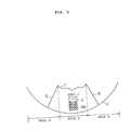
- Fig. 1 shows the structure of a reflector antenna device in accordance with a first embodiment of the present invention.
- the reflector antenna according to the first embodiment is made up of an auxiliary reflector 1 that receives an electric wave (or electromagnetic wave) radiated from a primary radiator 3 and reflects the electric wave, and a main reflector 2 that receives an electric wave reflected from the auxiliary reflector 1 and radiates the electric wave to a space.
- a stay 5 for spatially supporting the auxiliary reflector 1 is disposed on the main reflector 2.
- the electromagnetic wave radiated from the primary radiator 3 is reflected by the auxiliary reflector 1, further reflected by the main reflector 2, and then radiated to the space.
- the reflector antenna device in order to reduce a risk of the deterioration of the performance of an antenna, it is necessary to suppress the intensity of an electromagnetic wave that arrives in an area A of the main reflector 2 where the auxiliary reflector 1 is projected on the main reflector 2 in parallel with the radiating direction of the electromagnetic wave due to the main reflector 2. Also, it is necessary to design the reflector antenna device so that the gain and radiation pattern of the antenna characteristics which are defined by the electromagnetic wave that arrives in an area B of the main reflector 2 other than the area A have a desired characteristic.
- the intensity of the electromagnetic wave that arrives in the area A and the antenna characteristic are calculated by not a geometric optics technique, but a technique such as a physical optics method by which an influence of waves can be taken into account.
- the configurations of the auxiliary reflector and the main reflector are optimized so as to suppress the intensity of the electromagnetic wave that arrives in the area A to a predetermined level or lower and provide the gain and radiation pattern of the antenna characteristics defined by the electromagnetic wave that arrives in the area B in a main reflector 2 other than the area A with a desired characteristic by a technique by which the influence of the wave can be taken into account such as the physical optics method.
- the antenna is designed. It is assumed that the predetermined value related to the intensity of the electromagnetic wave, and the desired characteristic related to the gain and radiation pattern of the antenna characteristic are appropriately determined before the calculation in an optimization technique.
- Fig. 2 shows a designing procedure in accordance with this embodiment.
- the optimization based on a genetic algorithm (Yahya Rahmat-Samii, Electromagnetic Optimization by Genetic Algorithm, John Wiley & Sons, Inc) is also effective as the optimization technique.
- Step S1 the configuration of an auxiliary reflector 1 is first determined (Step S1).
- a determining method for example, a given function is given, a numeric number is appropriately inserted into the parameter of the function to determine the configuration of the auxiliary reflector 1.
- the selection of the function makes it possible to select various configurations such as a simple convex mirror shown in Fig. 12 or concave/convex portions on the surface configuration shown in Fig. 1.
- the configuration of the main reflector 2 is determined in the same method (Step S2).
- the electromagnetic wave in the area A is calculated to evaluate the power in the area A (Step S3).
- the electromagnetic wave should not arrive in the area A geometrically, but the electromagnetic wave is caused to arrive in the area A due to the wave property of the electromagnetic wave in fact, and the deterioration of the performance of the antenna is induced by the electromagnetic wave. Therefore, if the configurations of the auxiliary reflector 1 and the main reflector 2 can be selected so as to suppress the electromagnetic wave as much as possible, the deterioration of the performance of the antenna can be suppressed.
- the gain and radiation pattern of the antenna characteristic which are determined by the electromagnetic wave that arrives in the area B of the main reflector 2 other than the area A (Step S4). If the configurations of the auxiliary reflector 1 and the main reflector 2 can be selected so as to obtain the desired gain and radiation pattern of the antenna characteristic, the performance of the antenna can be improved.
- Step S5 it is judged whether a power in the area A which is obtained in Step S3 is equal to or lower than a predetermined value, and the gain and radiation pattern of the antenna characteristic which are obtained in Step S4 meet a desired predetermined characteristic, or not (Step S5).
- the process is returned to the beginning of the processing shown in Fig. 2, and the configurations of the auxiliary reflector 1 and the main reflector 2 are changed through Steps S1 and S2, and the same processing is conducted. In this way, calculation is repeatedly conducted in the nonlinear optimization technique for optimization until the two conditions can be met.
- a coordinate system is taken, and an initial configuration of the reflector antenna is determined.
- the coordinates of the auxiliary reflector 1 and the main reflector 2 are defined in a polar coordinate system, and it is assumed that a potential angle between the origin and an end portion of the auxiliary reflector 1 is ⁇ 0 .
- the auxiliary reflector coordinates P 0 s ( ⁇ , ⁇ ) are represented by the following expression from the distance r 0 ( ⁇ , ⁇ ) from the origin and direction vector ê r (or e r hat) on the auxiliary reflector 1 from the origin.
- the coordinates P 0 m ( ⁇ , ⁇ ) of the main reflector 2 are represented by the following expression on the basis of a reflecting direction ê s (or e s hat) in the auxiliary reflector 1, and a distance S 0 ( ⁇ , ⁇ ) of from a point on the auxiliary reflector 1 to a point on the main reflector 2.
- the configurations of the reflectors are determined by giving the distances r 0 ( ⁇ , ⁇ ) and S 0 ( ⁇ , ⁇ ).
- r 0 ( ⁇ , ⁇ ) and S 0 ( ⁇ , ⁇ ) may be defined as initial values in such a manner that the auxiliary reflector has a hyperboloid or an elliptical curved surface, or the main reflector has a paraboloidal surface, as in a Cassegrain antenna or a Gregorian antenna.
- the reflector antennas of various configurations can be represented by changing the coefficients f mn and g mn of the respective functions which define the auxiliary reflector configuration and the main reflector configuration.
- an electric power of the area A in Step S3 and the gain and radiation pattern in Step S4 can be obtained by using the physical optics method.
- a parameter that makes the evaluation function maximum can be obtained. Therefore, in Step S5, the evaluation function is regulated to be within a difference when the gain and the radiation pattern take desired values, and the electric power of the area A is equal to or lower than a desired value.
- the evaluation function E all is defined as represented by the following expression.
- E all E gain + E pat + E blocking
- E gain an evaluation function defined by a gain
- E pat an evaluation function defined by a pattern
- E blocking an evaluation function defined by an electric power of the auxiliary shielding area (area A) (13) where the following functions are defined.
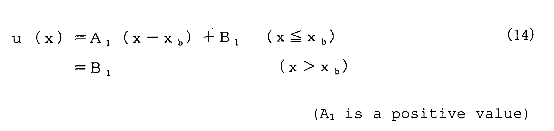
- u(x) is a function that monotonically increases by A 1 in an area of x b or less, and takes a constant value B 1 in an area of x b or more
- v(x) is a function that takes a constant value B 1 in an area of x b or less, and monotonically decreases by A 1 in an area of x b or more. Therefore, the function u(x) is used to realize an argument of a constant value or more, and the function V(x) is used to realize an argument of the constant value or less.
- the function u(x) is used to set the gain to a desired value or more
- the function v(x) is used in order to set the radiation pattern to a specified pattern or less, and set the electric power of the area A to a desired value or less.
- the target value may be set to a mask pattern per se or a mask pattern with a slight margin.
- the reflector surface parameter that sets the gain to a desired value or more, the radiation pattern to a specified pattern or less, and the electric power of the area A to a desired value or less, that is, the reflector surface configuration can be determined by optimizing the evaluation function by means of the genetic algorithm.
- the calculation is repeated until the electric power of the area A becomes a predetermined value or less, and the gain and radiation pattern of the antenna characteristic can meet desired predetermined characteristics, to thereby determine the configurations of the auxiliary reflector 1 and the main reflector 2. Accordingly, the reflector antenna that has the characteristic of a high performance and minimizes the deterioration of the antenna performance can be obtained.
- this embodiment is particularly effective to a small-size reflector antenna that is liable to induce the deterioration of the performance .
- Fig. 3 shows the structure of a reflector antenna in accordance with the first embodiment
- Fig. 4 shows a designing procedure thereof.
- the antenna design that is conducted taking into consideration a reduction in the electric power on an opening surface (or an opening portion, an area C of Fig. 3) of the primary radiator 3, or a reduction in the electric power of both areas of the area A and the area C.
- the antenna design made by taking into consideration the reduction in the electric power of both the areas A and C will be described.
- the structure of the reflector antenna according to this embodiment is fundamentally identical with those shown in Fig. 1 as described above, and therefore a description thereof will be omitted.
- the designing procedure according to this embodiment will be described with reference to Fig. 4.
- the configuration of the auxiliary reflector 1 is first determined (Step S11).
- the determining method is identical with that described above.
- the configuration of the main reflector 2 is determined according to the same method (Step S12).
- the electromagnetic wave of the area A and the area C is measured to evaluate the electric power of the area A and the area C (Step S13).
- the area C because a scattering wave is generated by the primary radiator 3, an undesirable contribution occurs and induces the deterioration of the antenna characteristics.
- the configurations of the auxiliary reflector 1 and the main reflector 2 can be selected so as to suppress the generation of the scattering wave as much as possible, the deterioration of the antenna performance can be suppressed.
- the area A the above description of the first embodiment is applied.
- the gain and radiation pattern of the antenna characteristics which are determined by the electromagnetic wave that arrives in the area B of the main reflector 2 other than the area A are calculated (Step S14). This calculation is identical with that described in the above first embodiment.
- Step S15 the process is returned to the beginning of the processing shown in Fig. 4, and the configurations of the auxiliary reflector 1 and the main reflector 2 are changed by Steps S11 and S12, and the same processing is conducted. In this manner, the calculation is repeatedly conducted in the nonlinear optimization technique for optimization until the two conditions can be met.
- the design of the antenna is optimized by the nonlinear optimization technique, it is possible to obtain the reflector antenna that has the characteristic of a high performance and minimizes the deterioration of the antenna performance.
- the deterioration of the performance which is attributable to the scattering wave due to the primary radiator 3 is taken into consideration. This is particularly effective when the reflector antenna is downsized and a distance between the primary radiator 3 and the auxiliary reflector 1 becomes shorter.
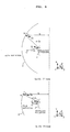
- FIG. 5(a) is a projection view of an antenna as viewed from a Z-axis direction.
- Fig. 5(b) shows a section G1 of Fig. 5(a), and
- Fig. 5(c) shows a section G2 of Fig. 5(a).
- the designing procedure is identical with that described in the first embodiment with reference to Fig. 2, but in order to realize asymmetric reflector antenna device, a coordinate system is taken as shown in Fig. 6, and the initial configurations of the auxiliary reflector 1 and the main reflector 2 are determined.
- the coordinates of the auxiliary reflector 1 and the main reflector 2 are defined by a polar coordinate system, and it is assumed that a potential angle between the origin and an end portion of the auxiliary reflector 1 is ⁇ 0 .
- the auxiliary reflector coordinates P 0 / s( ⁇ , ⁇ ) is represented by the following expression on the basis of a distance r 0 ( ⁇ , ⁇ ) from the origin and a direction vector ê r (or e r hat) on the auxiliary reflector 1.
- P 0 s ( ⁇ , ⁇ ) r ' 0 ( ⁇ , ⁇ )ê r ⁇ 0 ⁇ ⁇ ⁇ ⁇ 0 , 0 ⁇ ⁇ ⁇ 2 ⁇
- ê r (sin ⁇ cos ⁇ , sin ⁇ sin ⁇ , cos ⁇ ) where n and s (or n s hat) is a normal vector on the auxiliary reflector 1.
- the coordinates P 0 m ( ⁇ , ⁇ ) of the main reflector 2 are represented by the following expression on the basis of a reflecting direction ê s (or e s hat) in the auxiliary reflector 1, and a distance S 0 ( ⁇ , ⁇ ) of from a point on the auxiliary reflector 1 to a point on the main reflector 2.
- the reflector surface designed by the geometric optics technique which is an asymmetric reflector surface and whose path "r' 0 ( ⁇ , ⁇ ) + S' 0 ( ⁇ , ⁇ ) + t 0 " geometrical-optically determined becomes constant.
- the reflector antenna may be designed with respect to the reflector antenna of the initial configuration in accordance with the designing procedure shown in Fig. 2. Because the development function of the expressions (6) to (9) used in the first embodiment, and the evaluation function of the expression (10) to the expression (13), the expression (16), the expression (17), and the expression (18) can be used as they are, and the antenna is an asymmetric reflector antenna in the initial configurations of the reflector surface. Therefore, the asymmetric reflector can be designed.
- this embodiment it is possible to obtain a high-performance reflector antenna that minimizes the deterioration of the antenna-performance in the asymmetric reflector antenna as in the first embodiment. Also, this embodiment is particularly effective for a small-sized reflector antenna that is liable to induce the deterioration of the performance as in the first embodiment.
- a reflector antenna device will be described.
- This embodiment provides an asymmetric reflector antenna device and is directed to realize a high-performance antenna by using the same designing method as that of the second embodiment. That is, a feature of this embodiment resides in the antenna designed by taking into consideration a reduction in the electric power on an opening surface (or an opening portion, an area C of Fig. 7) of the primary radiator 3, or a reduction in the electric power of both areas A and C.
- Fig. 7(a) is a cross-sectional view taken along a section G1 of the antenna
- Fig. 7(b) is a cross-sectional view taken along a section G2 thereof.
- the projection view as viewed from the Z-axis direction of the antenna shown in Fig. 7 is referred to Fig. 5(a).
- the fourth embodiment is different from the second embodiment in that the asymmetric reflector surface is realized such that the initial configurations of the auxiliary reflector 1 and the main reflector 2 are given by the above expressions (19) to (21) and the above expressions (22) and (23), respectively, and by differing the distances r' 0 ( ⁇ , ⁇ ) and S' 0 ( ⁇ , ⁇ ) depending on the value of ⁇ .
- this embodiment it is possible to obtain a high-performance reflector antenna that minimizes the deterioration of the antenna performance in the asymmetric reflector antenna as in the first embodiment. Also, this embodiment is particularly effective for a small-sized reflector antenna that is liable to induce the deterioration of the performance as in the first embodiment.
- a reflector antenna device will be described with reference to Fig. 8.
- This embodiment has a feature that an electric wave absorbing member 6A is mounted on the peripheral portion of the opening surface of the primary radiator 3.
- the electric wave that arrives at the opening surface of the primary radiator 3 can be absorbed by the electric wave absorbing member 6A, the scattering wave can be suppressed from occurring due to the main reflector 3, and the deterioration of the performance due to the scattering wave can be suppressed.
- Other structures are identical with those in the above first or second embodiment, and their description will be omitted in this example.
- the configurations of the auxiliary reflector 1 and the main reflector 2 are determined according to any designing procedure of the above first and second embodiments.
- the electric wave absorbing member 6A is disposed on the peripheral portion of the opening surface of the primary radiator 3 so as to suppress the electric power that is scattered at the opening surface of the primary radiator 3, there is advantageous in that the deterioration of the antenna performance can be suppressed.
- the reflector antenna device is particularly effective when the device is downsized, and a distance between the primary radiator 3 and the auxiliary reflector 1 becomes shorter.
- a reflector antenna device will be described with reference to Fig. 9.
- This embodiment has a feature that an electric wave absorbing member 6B is mounted on the side surface of the primary radiator 3. With this structure, since the scattering wave generated by the electric wave that arrives at the side surface of the primary radiator 3 can be absorbed by the electric wave absorbing member 6B, the deterioration of the performance due to the scattering wave can be suppressed.
- Other structures are identical with those in the above first or second embodiment, and their description will be omitted in this example.
- the configurations of the auxiliary reflector 1 and the main reflector 2 are determined according to any designing procedure of the above first and second embodiments.
- the electric wave absorbing member 6B is disposed on the side surface of the primary radiator 3 so as to suppress the electric power that is scattered at the opening surface of the primary radiator 3, there is advantageous in that the deterioration of the antenna performance can be suppressed.
- the reflector antenna device has such an effect that the deterioration of the performance resulting from the scattering wave due to the primary radiator 3 can be particularly suppressed when the device is downsized, and a distance between the primary radiator 3 and the auxiliary reflector 1 becomes smaller.
- a reflector antenna device will be described with reference to Fig. 10.
- This embodiment has a feature that an electric wave absorbing member 6C is disposed on an area A where the auxiliary reflector 1 is projected onto the main reflector 2.
- an electric wave absorbing member 6C is disposed on an area A where the auxiliary reflector 1 is projected onto the main reflector 2.
- the electric wave absorbing member 6C is disposed in the area A so as to suppress the multiple reflected wave between the area A and the auxiliary reflector 1, there is advantageous in that the deterioration of the antenna performance can be suppressed.
- the reflector antenna device is particularly effective when the device is downsized, and a distance between the main reflector 2 and the auxiliary reflector 1 becomes smaller. Even in this case, the high-performance antenna can be realized.
- the electric wave absorbing member 6C is shaped in a plate, but the present invention is not limited to this, but the electric wave absorbing member 6C may be disposed along the surface of the area A.
- a reflector antenna device will be described with reference to Fig. 11.
- This embodiment has a feature that a reflecting plate 7 that is made up of a metal plate for reflecting an electromagnetic wave or the like is disposed with a predetermined slope with respect to the radiation direction of the electric wave due to the primary radiator 3 on the area A where the auxiliary reflector 1 is projected onto the main reflector 2.
- the predetermined slope is appropriately set so that the value of ⁇ is in a range of 90° ⁇ ⁇ ⁇ 180° assuming that an angle defined between the radiating direction of the electric wave from the primary radiator 3 and the reflecting plate 7 (or an extension of the reflecting plate 7) is ⁇ , for example, as shown in Fig. 11.
- the reflector antenna device is particularly effective when the device is downsized, and a distance between the main reflector 2 and the auxiliary reflector 1 becomes smaller. Even in this case, the high-performance antenna can be realized.
- the present invention is not limited to this case, but, for example, it is possible that the configuration of the main reflector 2 is fixed, and only the configuration of the auxiliary reflector 1 is optimized by the nonlinear optimization technique. Conversely, the configuration of the auxiliary reflector 1 may be fixed. In this case, the same effects as those in the above first or second embodiment can be obtained. In addition, since a process of determining the configuration of any one of the reflectors is unnecessary, a calculation load can be reduced.
Landscapes
- Aerials With Secondary Devices (AREA)
Abstract
Description





Claims (7)
- A reflector antenna device, comprising:characterized in that the configurations of the auxiliary reflector and the main reflector are designed such that an electric power in an area of the main reflector where the auxiliary reflector is projected on the main reflector in parallel with the radiating direction of the electric wave due to the main reflector is equal to or lower than a predetermined first threshold value, and a radiation pattern of the antenna which is determined by the area of the main reflector other than the area has a desired characteristic.an auxiliary reflector that receives an electric wave radiated from an opening portion by a primary radiator and reflects the electric wave; anda main reflector that receives the electric wave that is reflected by the auxiliary reflector and radiates the electric wave to a space,
- A reflector antenna device, comprising:characterized in that the configurations of the auxiliary reflector and the main reflector are designed such that an electric power on the opening portion of the primary radiator is equal to or lower than a predetermined second threshold value, and a radiation pattern of the antenna which is determined by another area of the main reflector other than an area of the main reflector where the auxiliary reflector is projected on the main reflector in parallel with the radiating direction of the electric wave due to the main reflector has a desired characteristic.an auxiliary reflector that receives an electric wave radiated from an opening portion by a primary radiator and reflects the electric wave; anda main reflector that receives the electric wave that is reflected by the auxiliary reflector and radiates the electric wave to a space,
- A reflector antenna device, comprising:characterized in that the configurations of the auxiliary reflector and the main reflector are designed such that an electric power in an area of the main reflector where the auxiliary reflector is projected on the main reflector in parallel with the radiating direction of the electric wave due to the main reflector is equal to or lower than a predetermined first threshold value, an electric power on an opening portion of the primary radiator is equal to or lower than a predetermined second threshold value, and a radiation pattern of the antenna which is determined by the area of the main reflector other than the area has a desired characteristic.an auxiliary reflector that receives an electric wave radiated from an opening portion by a primary radiator and reflects the electric wave; anda main reflector that receives the electric wave that is reflected by the auxiliary reflector and radiates the electric wave to a space,
- A reflector antenna device according to any one of claims 1 to 3, characterized in that an electric wave absorbing member for absorbing the electric wave is disposed on a peripheral portion of the opening portion of the primary radiator.
- A reflector antenna device according to any one of claims 1 to 4, characterized in that an electric wave absorbing member for absorbing the electric wave is disposed on a side surface of the primary radiator.
- A reflector antenna device according to any one of claims 1 to 5, characterized in that an electric wave absorbing member for absorbing the electric wave is disposed on the area of the main reflector where the auxiliary reflector is projected on the main reflector in parallel with the radiating direction of the electric wave due to the main reflector.
- An antenna device according to any one of claims 1 to 5, characterized in that a metal plate for reflecting an electric wave that arrives in the area of the main reflector where the auxiliary reflector is projected on the main reflector in parallel with the radiating direction of the electric wave due to the main reflector in a direction other than the direction of the auxiliary reflector is disposed on the area with a slope that is 90° or more and 180° or less with respect to the radiation direction of the electric wave.
Priority Applications (1)
| Application Number | Priority Date | Filing Date | Title |
|---|---|---|---|
| EP09010296.3A EP2117076B1 (en) | 2003-08-13 | 2003-12-25 | Reflector antenna device |
Applications Claiming Priority (3)
| Application Number | Priority Date | Filing Date | Title |
|---|---|---|---|
| JP2003292760 | 2003-08-13 | ||
| JP2003292760 | 2003-08-13 | ||
| PCT/JP2003/016776 WO2005018049A1 (en) | 2003-08-13 | 2003-12-25 | Reflector antena |
Related Child Applications (2)
| Application Number | Title | Priority Date | Filing Date |
|---|---|---|---|
| EP09010296.3A Division EP2117076B1 (en) | 2003-08-13 | 2003-12-25 | Reflector antenna device |
| EP09010296.3A Division-Into EP2117076B1 (en) | 2003-08-13 | 2003-12-25 | Reflector antenna device |
Publications (3)
| Publication Number | Publication Date |
|---|---|
| EP1538704A1 true EP1538704A1 (en) | 2005-06-08 |
| EP1538704A4 EP1538704A4 (en) | 2005-10-19 |
| EP1538704B1 EP1538704B1 (en) | 2016-08-24 |
Family
ID=34190962
Family Applications (2)
| Application Number | Title | Priority Date | Filing Date |
|---|---|---|---|
| EP09010296.3A Expired - Lifetime EP2117076B1 (en) | 2003-08-13 | 2003-12-25 | Reflector antenna device |
| EP03768260.6A Expired - Lifetime EP1538704B1 (en) | 2003-08-13 | 2003-12-25 | Reflector antena |
Family Applications Before (1)
| Application Number | Title | Priority Date | Filing Date |
|---|---|---|---|
| EP09010296.3A Expired - Lifetime EP2117076B1 (en) | 2003-08-13 | 2003-12-25 | Reflector antenna device |
Country Status (4)
| Country | Link |
|---|---|
| US (1) | US7081863B2 (en) |
| EP (2) | EP2117076B1 (en) |
| JP (1) | JP4468300B2 (en) |
| WO (1) | WO2005018049A1 (en) |
Cited By (1)
| Publication number | Priority date | Publication date | Assignee | Title |
|---|---|---|---|---|
| WO2008051702A1 (en) * | 2006-10-23 | 2008-05-02 | Harris Corporation | Antenna with shaped asymmetric main reflector and subreflector with asymmetric waveguide feed |
Families Citing this family (4)
| Publication number | Priority date | Publication date | Assignee | Title |
|---|---|---|---|---|
| DE102005049242B4 (en) * | 2005-10-14 | 2008-01-24 | Vega Grieshaber Kg | Parabolic antenna with conical lens for level radar |
| RU2380802C1 (en) * | 2008-11-17 | 2010-01-27 | Джи-хо Ан | Compact multibeam mirror antenna |
| US8914258B2 (en) * | 2011-06-28 | 2014-12-16 | Space Systems/Loral, Llc | RF feed element design optimization using secondary pattern |
| US9472856B2 (en) | 2012-04-02 | 2016-10-18 | Furuno Electric Co., Ltd. | Antenna |
Family Cites Families (16)
| Publication number | Priority date | Publication date | Assignee | Title |
|---|---|---|---|---|
| US3133284A (en) * | 1959-03-02 | 1964-05-12 | Rca Corp | Paraboloidal antenna with compensating elements to reduce back radiation into feed |
| GB1326210A (en) * | 1969-09-16 | 1973-08-08 | Kokusai Denshin Denwa Co Ltd | Antenna using at least one reflector |
| DE2359870A1 (en) * | 1973-11-30 | 1975-06-12 | Rohde & Schwarz | Cassegrain-type directional aerial - avoids radiation hole behind auxiliary reflector by interconnected additional directional aerial and exciter |
| FR2445040A1 (en) * | 1978-12-22 | 1980-07-18 | Thomson Csf | CONICAL SCANNING ANTENNA FOR RADAR, ESPECIALLY TRACKING RADAR |
| JPS63169803A (en) * | 1987-01-07 | 1988-07-13 | Mitsubishi Electric Corp | Antenna system |
| US5182569A (en) * | 1988-09-23 | 1993-01-26 | Alcatel N.V. | Antenna having a circularly symmetrical reflector |
| US5373302A (en) * | 1992-06-24 | 1994-12-13 | The United States Of America As Represented By The Administrator Of The National Aeronautics And Space Administration | Double-loop frequency selective surfaces for multi frequency division multiplexing in a dual reflector antenna |
| FR2713404B1 (en) * | 1993-12-02 | 1996-01-05 | Alcatel Espace | Oriental antenna with conservation of polarization axes. |
| JP3440687B2 (en) | 1996-04-16 | 2003-08-25 | 三菱電機株式会社 | Mirror shaped shaped beam antenna |
| DE19817766A1 (en) | 1998-04-21 | 1999-11-11 | Daimler Chrysler Ag | Centrally powered antenna system and method for optimizing such an antenna system |
| US6522305B2 (en) * | 2000-02-25 | 2003-02-18 | Andrew Corporation | Microwave antennas |
| US6741216B2 (en) * | 2001-03-02 | 2004-05-25 | Mitsubishi Denki Kabushiki Kaisha | Reflector antenna |
| JP2002330020A (en) | 2001-05-02 | 2002-11-15 | Omron Corp | Horn antenna design method, horn antenna and Cassegrain antenna |
| US6831613B1 (en) * | 2003-06-20 | 2004-12-14 | Harris Corporation | Multi-band ring focus antenna system |
| US6982679B2 (en) * | 2003-10-27 | 2006-01-03 | Harris Corporation | Coaxial horn antenna system |
| US6911953B2 (en) * | 2003-11-07 | 2005-06-28 | Harris Corporation | Multi-band ring focus antenna system with co-located main reflectors |
-
2003
- 2003-12-25 EP EP09010296.3A patent/EP2117076B1/en not_active Expired - Lifetime
- 2003-12-25 WO PCT/JP2003/016776 patent/WO2005018049A1/en not_active Ceased
- 2003-12-25 US US10/526,220 patent/US7081863B2/en not_active Expired - Lifetime
- 2003-12-25 JP JP2005507772A patent/JP4468300B2/en not_active Expired - Fee Related
- 2003-12-25 EP EP03768260.6A patent/EP1538704B1/en not_active Expired - Lifetime
Cited By (1)
| Publication number | Priority date | Publication date | Assignee | Title |
|---|---|---|---|---|
| WO2008051702A1 (en) * | 2006-10-23 | 2008-05-02 | Harris Corporation | Antenna with shaped asymmetric main reflector and subreflector with asymmetric waveguide feed |
Also Published As
| Publication number | Publication date |
|---|---|
| EP2117076A1 (en) | 2009-11-11 |
| EP2117076B1 (en) | 2016-06-01 |
| US20060001588A1 (en) | 2006-01-05 |
| WO2005018049A1 (en) | 2005-02-24 |
| EP1538704B1 (en) | 2016-08-24 |
| JPWO2005018049A1 (en) | 2006-10-12 |
| EP1538704A4 (en) | 2005-10-19 |
| US7081863B2 (en) | 2006-07-25 |
| JP4468300B2 (en) | 2010-05-26 |
Similar Documents
| Publication | Publication Date | Title |
|---|---|---|
| US20160372835A1 (en) | Imaging antenna systems with compensated optical aberrations based on unshaped surface reflectors | |
| US6977622B2 (en) | Shaped-reflector multibeam antennas | |
| JPS5991708A (en) | Antenna device | |
| EP2117076B1 (en) | Reflector antenna device | |
| EP4044371A1 (en) | Reflector antenna device | |
| KR102418087B1 (en) | Reflective antenna apparatus and method for design thereof | |
| JP2003218630A (en) | Antenna device | |
| JP3440687B2 (en) | Mirror shaped shaped beam antenna | |
| JPH07321544A (en) | Multi-frequency shared antenna | |
| JP4151593B2 (en) | Double reflector antenna device | |
| JP6598727B2 (en) | Reflect array antenna | |
| EP4199252B1 (en) | Optical system for enhanced wide scan capability of array antennas | |
| JP3314904B2 (en) | Multi-beam antenna | |
| JP3043768B2 (en) | Mirror modified antenna | |
| JPS6313567B2 (en) | ||
| JPH09232861A (en) | Reflector antenna | |
| Shiode et al. | A study of wideband reflectarray antenna using ring-style resonator elements | |
| JP4080137B2 (en) | Multi-frequency band antenna | |
| JP2889084B2 (en) | Modification method of double reflector antenna device | |
| Karimkashi et al. | Blockage minimization in symmetric dual-reflector antennas for different edge taper values | |
| JPS58175302A (en) | Antenna device | |
| AU2003248292B2 (en) | Shaped-reflector Multibeam Antennas | |
| JPH0347764B2 (en) | ||
| JP2001292022A (en) | Four-reflection mirror focused beam feeding system | |
| JP2001339236A (en) | Multi-frequency band shared antenna |
Legal Events
| Date | Code | Title | Description |
|---|---|---|---|
| PUAI | Public reference made under article 153(3) epc to a published international application that has entered the european phase |
Free format text: ORIGINAL CODE: 0009012 |
|
| 17P | Request for examination filed |
Effective date: 20050308 |
|
| AK | Designated contracting states |
Kind code of ref document: A1 Designated state(s): AT BE BG CH CY CZ DE DK EE ES FI FR GB GR HU IE IT LI LU MC NL PT RO SE SI SK TR |
|
| AX | Request for extension of the european patent |
Extension state: AL LT LV MK |
|
| A4 | Supplementary search report drawn up and despatched |
Effective date: 20050902 |
|
| RIC1 | Information provided on ipc code assigned before grant |
Ipc: 7H 01Q 19/02 B Ipc: 7H 01Q 19/19 A |
|
| RAP1 | Party data changed (applicant data changed or rights of an application transferred) |
Owner name: MITSUBISHI DENKI KABUSHIKI KAISHA |
|
| DAX | Request for extension of the european patent (deleted) | ||
| RBV | Designated contracting states (corrected) |
Designated state(s): DE FR GB IT |
|
| 17Q | First examination report despatched |
Effective date: 20061116 |
|
| GRAP | Despatch of communication of intention to grant a patent |
Free format text: ORIGINAL CODE: EPIDOSNIGR1 |
|
| RIC1 | Information provided on ipc code assigned before grant |
Ipc: H01Q 19/19 20060101AFI20160302BHEP |
|
| INTG | Intention to grant announced |
Effective date: 20160316 |
|
| GRAS | Grant fee paid |
Free format text: ORIGINAL CODE: EPIDOSNIGR3 |
|
| GRAA | (expected) grant |
Free format text: ORIGINAL CODE: 0009210 |
|
| AK | Designated contracting states |
Kind code of ref document: B1 Designated state(s): DE FR GB IT |
|
| REG | Reference to a national code |
Ref country code: GB Ref legal event code: FG4D |
|
| REG | Reference to a national code |
Ref country code: DE Ref legal event code: R096 Ref document number: 60349314 Country of ref document: DE |
|
| REG | Reference to a national code |
Ref country code: FR Ref legal event code: PLFP Year of fee payment: 14 |
|
| REG | Reference to a national code |
Ref country code: DE Ref legal event code: R097 Ref document number: 60349314 Country of ref document: DE |
|
| PLBE | No opposition filed within time limit |
Free format text: ORIGINAL CODE: 0009261 |
|
| STAA | Information on the status of an ep patent application or granted ep patent |
Free format text: STATUS: NO OPPOSITION FILED WITHIN TIME LIMIT |
|
| 26N | No opposition filed |
Effective date: 20170526 |
|
| REG | Reference to a national code |
Ref country code: FR Ref legal event code: PLFP Year of fee payment: 15 |
|
| REG | Reference to a national code |
Ref country code: DE Ref legal event code: R084 Ref document number: 60349314 Country of ref document: DE |
|
| REG | Reference to a national code |
Ref country code: GB Ref legal event code: 746 Effective date: 20190123 |
|
| PGFP | Annual fee paid to national office [announced via postgrant information from national office to epo] |
Ref country code: DE Payment date: 20201216 Year of fee payment: 18 Ref country code: IT Payment date: 20201110 Year of fee payment: 18 Ref country code: GB Payment date: 20201216 Year of fee payment: 18 Ref country code: FR Payment date: 20201112 Year of fee payment: 18 |
|
| REG | Reference to a national code |
Ref country code: DE Ref legal event code: R119 Ref document number: 60349314 Country of ref document: DE |
|
| GBPC | Gb: european patent ceased through non-payment of renewal fee |
Effective date: 20211225 |
|
| PG25 | Lapsed in a contracting state [announced via postgrant information from national office to epo] |
Ref country code: GB Free format text: LAPSE BECAUSE OF NON-PAYMENT OF DUE FEES Effective date: 20211225 Ref country code: DE Free format text: LAPSE BECAUSE OF NON-PAYMENT OF DUE FEES Effective date: 20220701 |
|
| PG25 | Lapsed in a contracting state [announced via postgrant information from national office to epo] |
Ref country code: FR Free format text: LAPSE BECAUSE OF NON-PAYMENT OF DUE FEES Effective date: 20211231 |
|
| PG25 | Lapsed in a contracting state [announced via postgrant information from national office to epo] |
Ref country code: IT Free format text: LAPSE BECAUSE OF NON-PAYMENT OF DUE FEES Effective date: 20211225 |