EP1538484A1 - EUV illumination system and lithographic apparatus - Google Patents
EUV illumination system and lithographic apparatus Download PDFInfo
- Publication number
- EP1538484A1 EP1538484A1 EP04078219A EP04078219A EP1538484A1 EP 1538484 A1 EP1538484 A1 EP 1538484A1 EP 04078219 A EP04078219 A EP 04078219A EP 04078219 A EP04078219 A EP 04078219A EP 1538484 A1 EP1538484 A1 EP 1538484A1
- Authority
- EP
- European Patent Office
- Prior art keywords
- radiation
- collection
- extreme ultra
- production
- lithographic apparatus
- Prior art date
- Legal status (The legal status is an assumption and is not a legal conclusion. Google has not performed a legal analysis and makes no representation as to the accuracy of the status listed.)
- Ceased
Links
Images


Classifications
-
- G—PHYSICS
- G03—PHOTOGRAPHY; CINEMATOGRAPHY; ANALOGOUS TECHNIQUES USING WAVES OTHER THAN OPTICAL WAVES; ELECTROGRAPHY; HOLOGRAPHY
- G03F—PHOTOMECHANICAL PRODUCTION OF TEXTURED OR PATTERNED SURFACES, e.g. FOR PRINTING, FOR PROCESSING OF SEMICONDUCTOR DEVICES; MATERIALS THEREFOR; ORIGINALS THEREFOR; APPARATUS SPECIALLY ADAPTED THEREFOR
- G03F7/00—Photomechanical, e.g. photolithographic, production of textured or patterned surfaces, e.g. printing surfaces; Materials therefor, e.g. comprising photoresists; Apparatus specially adapted therefor
- G03F7/70—Microphotolithographic exposure; Apparatus therefor
- G03F7/708—Construction of apparatus, e.g. environment aspects, hygiene aspects or materials
- G03F7/70858—Environment aspects, e.g. pressure of beam-path gas, temperature
-
- G—PHYSICS
- G03—PHOTOGRAPHY; CINEMATOGRAPHY; ANALOGOUS TECHNIQUES USING WAVES OTHER THAN OPTICAL WAVES; ELECTROGRAPHY; HOLOGRAPHY
- G03F—PHOTOMECHANICAL PRODUCTION OF TEXTURED OR PATTERNED SURFACES, e.g. FOR PRINTING, FOR PROCESSING OF SEMICONDUCTOR DEVICES; MATERIALS THEREFOR; ORIGINALS THEREFOR; APPARATUS SPECIALLY ADAPTED THEREFOR
- G03F7/00—Photomechanical, e.g. photolithographic, production of textured or patterned surfaces, e.g. printing surfaces; Materials therefor, e.g. comprising photoresists; Apparatus specially adapted therefor
- G03F7/70—Microphotolithographic exposure; Apparatus therefor
- G03F7/708—Construction of apparatus, e.g. environment aspects, hygiene aspects or materials
- G03F7/70908—Hygiene, e.g. preventing apparatus pollution, mitigating effect of pollution or removing pollutants from apparatus
- G03F7/70916—Pollution mitigation, i.e. mitigating effect of contamination or debris, e.g. foil traps
-
- G—PHYSICS
- G03—PHOTOGRAPHY; CINEMATOGRAPHY; ANALOGOUS TECHNIQUES USING WAVES OTHER THAN OPTICAL WAVES; ELECTROGRAPHY; HOLOGRAPHY
- G03F—PHOTOMECHANICAL PRODUCTION OF TEXTURED OR PATTERNED SURFACES, e.g. FOR PRINTING, FOR PROCESSING OF SEMICONDUCTOR DEVICES; MATERIALS THEREFOR; ORIGINALS THEREFOR; APPARATUS SPECIALLY ADAPTED THEREFOR
- G03F7/00—Photomechanical, e.g. photolithographic, production of textured or patterned surfaces, e.g. printing surfaces; Materials therefor, e.g. comprising photoresists; Apparatus specially adapted therefor
- G03F7/70—Microphotolithographic exposure; Apparatus therefor
- G03F7/70058—Mask illumination systems
- G03F7/70091—Illumination settings, i.e. intensity distribution in the pupil plane or angular distribution in the field plane; On-axis or off-axis settings, e.g. annular, dipole or quadrupole settings; Partial coherence control, i.e. sigma or numerical aperture [NA]
Definitions
- the present invention relates to a lithographic apparatus, an illumination system, and a method for providing a projection beam of EUV radiation.
- a lithographic apparatus is a machine that applies a desired pattern onto a target portion of a substrate.
- Lithographic apparatus can be used, for example, in the manufacture of integrated circuits (ICs).
- a patterning structure such as a mask, may be used to generate a circuit pattern corresponding to an individual layer of the IC, and this pattern can be imaged onto a target portion (comprising part of one or several dies) on a substrate (e.g., a silicon wafer) that has a layer of radiation-sensitive material (resist).
- a single substrate will contain a network of adjacent target portions that are successively exposed.
- lithographic apparatus include so-called steppers, in which each target portion is irradiated by exposing an entire pattern onto the target portion in one go, and so-called scanners, in which each target portion is irradiated by scanning the pattern through the projection beam in a given direction (the "scanning"-direction) while synchronously scanning the substrate parallel or anti-parallel to this direction.
- Lithographic apparatus include, for example, an illumination system for providing a projection beam of radiation.
- the illumination system typically includes a radiation-production system for producing extreme ultra-violet radiation (EUV), and a radiation-collection system for collection of the EUV produced by the radiation-production system.
- EUV extreme ultra-violet
- EUV extreme ultra-violet
- a laser produced plasma source usually comprises an object, which may also be a gas, that is hit by a laser. This causes a secondary emission, e.g. EUV light, as well as the production of undesired particles, referred to as particles or debris particles.
- the particles that are produced as a by-product of the production of the EUV radiation typically enter the radiation-collection system, which causes pollution, or contamination. If the particles have a high velocity, the particles may cause damage to the radiation-collection system. It is possible that other parts of the illumination system that are "downstream,” with respect to the radiation-collection system, may suffer from the presence and/or impact of these high velocity particles.
- debris particles are understood to encompass ions, as well as neutrals (both fast and slow), in sizes ranging form atomic or ionic dimensions up to and including micron-sized particles.
- Embodiments are, in particular, related to a lithographic apparatus comprising an illumination system for providing a projection beam of radiation and to such an illumination system.
- an illumination system comprises a radiation-production system for producing extreme ultra-violet (EUV) radiation and, as a by-product, particles which move substantially into a particle-movement direction.
- the illumination system also comprises a radiation-collection system for collecting extreme ultra-violet (EUV) radiation.
- EUV extreme ultra-violet
- a lithographic apparatus comprising an illumination system for providing a projection beam of radiation, a support structure for supporting a patterning structure, the patterning structure serving to impart the projection beam with a pattern in its cross-section, a substrate table for holding a substrate, and a projection system for projecting the patterned beam onto a target portion of the substrate.
- the illumination system comprises a radiation-production system for producing extreme ultra-violet (EUV) radiation, and a radiation-collection system for collecting extreme ultra-violet (EUV) radiation.
- EUV extreme ultra-violet
- the radiation-production system as a by-product, produces particles which move substantially into a particle-movement direction.
- the radiation-collection system is substantially arranged to collect extreme ultra-violet (EUV) radiation, which radiates substantially into a collection-direction. The collection-direction is substantially different from the particle-movement direction.
- a lithographic apparatus that includes an illumination system that provides a beam of radiation, and a support structure that supports a patterning structure.
- the patterning structure is configured to impart the beam of radiation with a pattern in its cross-section.
- the apparatus also includes a substrate support that supports a substrate, and a projection system that projects the patterned beam onto a target portion of the substrate.
- the illumination system includes a radiation-production system that produces extreme ultra-violet radiation, and a radiation-collection system that collects extreme ultra-violet radiation. Particles that are produced as a by-product of extreme ultra-violet radiation production move substantially in a particle-movement direction.
- the radiation-collection system is arranged to collect extreme ultra-violet radiation which radiates in a collection-direction, which is substantially different from the particle-movement direction.
- the radiation-collection system of a lithographic apparatus is substantially arranged to collect EUV radiation that radiates into a direction different from the particle-movement direction, much less particles, if any at all, will enter the radiation-collection system when compared to the number of particles entering the radiation collection system in a prior art lithographic apparatus.
- pollution and/or, if the particles have a high velocity damage of the radiation-collection system is reduced.
- other parts of the illumination system that are "downstream," with respect to the radiation-collection system will suffer much less, if at all, from the presence and/or impact of the high velocity particles, as compared to a known illumination system.
- the radiation-production system may comprise two electrodes oppositely chargeable, wherein an electric field, which can be generated between the electrodes, substantially follows an axial direction of the radiation-production system. This ensures that a path in the particle-movement direction that will be substantially followed by charged particles produced during production of the EUV will be well defined.
- generally magnetic-hydrodynamic forces are produced during a high current flow, further ensuring that particles follow the particle-movement direction along a well-defined path.
- a direction which differs from the particle-movement direction will also be well-defined, leading to minimal collection of particles by the radiation-collection system.
- Charged particles may drag neutral particles along or may, if their kinetic energy is high enough, ionize neutral particles. These ionized particles will then also follow the electric field generated by the two oppositely charged electrodes.
- the directional movement of ionized or neutral particles of atomic or molecular dimensions comprises a flow which can further drag along nano-and micron sized particles, not unlike friction at a macroscopic level.
- the collection-direction is a radial direction of the radiation-production system. This dramatically reduces the collection of particles in the radiation-collection system as at least most, if not all, of the charged particles will move into the axial direction instead of into the radial direction.
- At least one of the two electrodes is substantially a ring-shaped electrode, such that the axial direction of each ring-shaped electrode substantially coincides with the axial direction of the radiation-production system. This allows for the charged particles to move along the axis through the ring-shaped electrode from where the charged particles can be caught, for instance, by a pump, to avoid re-entering the space between the electrodes.
- the radiation-collection system has an optical axis substantially parallel to the axial direction of the radiation-production system. This allows for an optimal collection of the radiation.
- the radiation-collection system may, in this case, be substantially ring-shaped with a mirror surface at the inner wall. The mirror surface will be inclined such that the radiation is reflected towards the axial direction.
- the radiation-collection system may also include an optical system for aiding in providing the projection beam of radiation.
- an illumination system for providing a projection beam of radiation.
- the illumination system comprising a radiation-production system for producing extreme ultra-violet (EUV) radiation, and a radiation-collection system for collecting extreme ultra-violet (EUV) radiation.
- EUV extreme ultra-violet
- the radiation-production system as a by-product, produces particles which move substantially into a particle-movement direction.
- the radiation-collection system is substantially arranged to collect extreme ultra-violet (EUV) radiation which radiates substantially into a collection-direction. The collection-direction is substantially different from the particle-movement direction.
- a method for providing a projection beam of radiation comprises producing extreme ultra-violet (EUV) radiation, and substantially collecting extreme ultra-violet (EUV) radiation which radiates substantially into a collection direction.
- EUV extreme ultra-violet
- EUV extreme ultra-violet
- particles are produced, which move substantially into a particle-movement direction.
- the collection direction is substantially different from the particle-movement direction.
- lithographic apparatus in the manufacture of ICs, it should be understood that the lithographic apparatus described herein may have other applications, such as the manufacture of integrated optical systems, guidance and detection patterns for magnetic domain memories, liquid-crystal displays (LCDs), thin film magnetic heads, etc.
- LCDs liquid-crystal displays
- any use of the terms “wafer” or “die” herein may be considered as synonymous with the more general terms “substrate” or “target portion,” respectively.
- the substrate referred to herein may be processed, before or after exposure, in for example a track (a tool that typically applies a layer of resist to a substrate and develops the exposed resist) or a metrology or inspection tool.
- the disclosure herein may be applied to such and other substrate processing tools.
- the substrate may be processed more than once, for example in order to create a multi-layer IC, so that the term substrate used herein may also refer to a substrate that already contains multiple processed layers.
- radiation and “beam” used herein encompass extreme ultra-violet (EUV) radiation (e.g. having a wavelength in the range of 5-20 nm).
- EUV extreme ultra-violet
- patterning device or “patterning structure” used herein should be broadly interpreted as referring to a device or structure that can be used to impart a projection beam with a pattern in its cross-section such as to create a pattern in a target portion of the substrate. It should be noted that the pattern imparted to the projection beam may not exactly correspond to the desired pattern in the target portion of the substrate. Generally, the pattern imparted to the projection beam will correspond to a particular functional layer in a device being created in the target portion, such as an integrated circuit.
- the patterning structure may be transmissive or reflective.
- Examples of a patterning structure include masks, programmable mirror arrays, and programmable LCD panels.
- Masks are well known in lithography, and include mask types such as binary, alternating phase-shift, and attenuated phase-shift, as well as various hybrid mask types.
- An example of a programmable mirror array employs a matrix arrangement of small mirrors, each of which can be individually tilted so as to reflect an incoming radiation beam in different directions; in this manner, the reflected beam is patterned.
- the support structure may be a frame or table, for example, which may be fixed or movable as needed and which may ensure that the patterning means is at a desired position, for example with respect to the projection system. Any use of the terms "reticle” or “mask” herein may be considered synonymous with the more general term "patterning means.”
- projection system used herein should be broadly interpreted as encompassing various types of projection systems, including refractive optical systems, reflective optical systems, and catadioptric optical systems, as appropriate for the exposure radiation being used, or for other factors such as the use of an immersion fluid or the use of a vacuum. Any use of the term “lens” herein may be considered as synonymous with the more general term “projection system.”
- the illumination system may also encompass various types of optical components, including refractive, reflective, and catadioptric optical components for directing, shaping, or controlling the projection beam of radiation, and such components may also be referred to below, collectively or singularly, as a "lens.”
- the lithographic apparatus may be of a type having two (dual stage) or more substrate tables (and/or two or more mask tables).
- the additional tables may be used in parallel, or preparatory steps may be carried out on one or more tables, while one or more other tables are being used for exposure.
- the lithographic apparatus may also be of a type wherein the substrate is immersed in a liquid having a relatively high refractive index, e.g. water, so as to fill a space between the final element of the projection system and the substrate.
- Immersion liquids may also be applied to other spaces in the lithographic apparatus, for example, between the mask and the first element of the projection system. Immersion techniques are well known in the art for increasing the numerical aperture of projection systems.
- Figure 1 depicts schematically a lithographic apparatus according to an embodiment of the invention
- Figure 2 depicts schematically a radiation-production system and a radiation-collection system according to an embodiment of the invention
- Figure 3 depicts schematically a view along direction V in Figure 2;
- FIG. 4 depicts schematically an illumination system according to an embodiment of the invention.
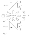
- Figure 5 depicts a radiation-production system and a radiaton collection system according to an embodiment of the invention.
- FIG. 1 schematically depicts a lithographic apparatus according to a particular embodiment of the invention.
- the apparatus comprises an illumination system (ILS) comprising an illuminator IL for providing a projection beam PB of radiation (e.g. EUV radiation), a first support structure (e.g. a mask table) MT for supporting a patterning structure (e.g. a mask) MA and connected to a first positioning device PM for accurately positioning the patterning structure with respect to item PL, a substrate table (e.g. a wafer table) WT for holding a substrate (e.g. a resist coated wafer) W and connected to a second positioning device PW for accurately positioning the substrate with respect to item PL, and a projection system (e.g.
- IVS illumination system
- PB of radiation e.g. EUV radiation
- a first support structure e.g. a mask table
- MT for supporting a patterning structure (e.g. a mask) MA and connected to a first positioning device PM
- substrate table for imaging a pattern imparted to the projection beam PB by patterning means MA onto a target portion C (e.g. comprising one or more dies) of the substrate W.
- substrate table can also be considered or termed as a substrate support. It should be understood that the term substrate support or substrate table broadly refers to a structure that supports, holds, or carries a substrate.
- the apparatus is of a reflective type (e.g. employing a reflective mask or a programmable mirror array of a type as referred to above).
- the apparatus may be of a transmissive type (e.g. employing a transmissive mask).
- the illuminator IL receives a beam of radiation from a radiation source SO.
- the source and the lithographic apparatus may be separate entities, such as when the source is a plasma discharge source. In such cases, the source may not necessarily be considered to form part of the lithographic apparatus and the radiation beam is generally passed from the source SO to the illuminator IL with the aid of a radiation collector comprising, for example, suitable collecting mirrors and/or a spectral purity filter. In other cases, the source may be an integral part of the apparatus, such as when the source is a mercury lamp.
- the source SO and the illuminator IL may also be referred to as a radiation system.
- the illuminator IL may comprise an adjusting device for adjusting the angular intensity distribution of the beam.
- a conditioned beam of radiation referred to as the projection beam PB, having a desired uniformity and intensity distribution in its cross section.
- the projection beam PB is incident on the mask MA, which is held on the mask table MT. Being reflected by the mask MA, the projection beam PB passes through the lens PL, which focuses the beam onto a target portion C of the substrate W.
- the substrate table WT can be moved accurately, so as to position different target portions C in the path of the beam PB.
- the first positioning device PM and position sensor IF1 can be used to accurately position the mask MA with respect to the path of the beam PB, such as after mechanical retrieval from a mask library, or during a scan.
- the mask table MT may be connected to a short stroke actuator only, or may be fixed.
- the mask MA and the substrate W may be aligned using mask alignment marks M1, M2 and substrate alignment marks P1, P2.
- FIG. 2 shows schematically at least a part of an illumination system ILS of a lithographic apparatus according to an embodiment of the invention.
- the illumination system ILS comprises at least a radiation-production system RPS for producing extreme ultraviolet (EUV) radiation.
- the radiation is schematically indicated by large arrows R.
- This radiation-production system RPS in particular, the radiation source SO, produces as by-product particles which move substantially into a particle-movement direction PMD, schematically indicated by the dotted line and arrows PMD.
- the radiation-production system RPS may be a plasma discharge source known in itself.
- the radiation-production system may comprise two electrodes E1, E2 oppositely chargeable.
- One or both of the electrodes E1, E2 may be ring shaped.
- the particle-movement direction PMD coincides with the axial direction of the radiation-production system, as charged particles will follow the electric field lines.
- magnetic-hydro-dynamic forces may have also been generated, thereby ensuring that the charged particles move along the particle movement direction PMD.
- the charged particles may "drag along" neutral particles in their movement into the axial direction and these ions, neutral atoms, and molecules may form a flow which can further "drag along" nanosized and/or micron sized particles.
- the illumination system may also comprise a radiation-collection system RCS for collecting extreme ultraviolet (EUV) radiation.
- the radiation-collection system RCS is substantially arranged to collect extreme ultraviolet EUV radiation which radiates substantially into a radiation-collection direction.
- the radiation-collection direction is substantially different from the particle movement direction PMD. The likelihood that particles will enter the radiation collection system is therefore reduced.
- the collection direction is a radial direction of the radiation-production system.
- Figure 3 shows schematically a view along direction V in Figure 2.
- Figure 3 shows three different zones.
- zone I both radiation and particles move towards the viewer looking into direction V.
- Zone II shows the ring-shaped electrode E2.
- Zone III is the zone in which substantially less particles move into a radial direction of the radiation-production system RPS, as compared to the number of particles moving into the axial direction, i.e., the particle movement direction PMD.
- arranging the radiation-collection system RCS such that the collection direction is a radial direction of the radiation-production system RPS results in a reduction of the number of particles entering the radiation collection system RCS, as compared to the number of particles entering the radiation collection system RCS in the known art.
- the radiation-collection system RCS has an optical axis substantially parallel to the radial direction.
- the radiation-collection system RCS may, as well known to those skilled in the art, comprise suitable collection mirrors CM and/or a spectral purity filter SPF to produce a radiation beam which is passed on to the illuminator IL shown in Figure 1.
- the radiation-collection system RCS has an optical axis substantially parallel to the axial direction of the radiation-production system RPS.
- the radiation-collection system RCS comprises mirrors MR1, MR2 which are positioned such that the radiation collected by the radiation-collection system RCS is directed into the axial direction of the radiation-production system RPS. It is, of course, also possible that the radiation may be directed into an opposite direction as the direction shown in Figure 5.
- the mirrors MR1, MR2 may each be part of one ring shaped mirror.
- the radiation collection system may further comprise an optical system (not shown) for aiding in providing the projecting beam of radiation.
- the optical system may be part of the illumination system, or may be regarded as the illuminator IL as shown in Figure 1.
Landscapes
- Health & Medical Sciences (AREA)
- Epidemiology (AREA)
- Life Sciences & Earth Sciences (AREA)
- Atmospheric Sciences (AREA)
- Public Health (AREA)
- General Physics & Mathematics (AREA)
- Physics & Mathematics (AREA)
- Environmental & Geological Engineering (AREA)
- Engineering & Computer Science (AREA)
- Toxicology (AREA)
- Exposure And Positioning Against Photoresist Photosensitive Materials (AREA)
- Exposure Of Semiconductors, Excluding Electron Or Ion Beam Exposure (AREA)
- X-Ray Techniques (AREA)
Abstract
A lithographic apparatus is disclosed. The lithographic apparatus includes an illumination system (ILS) that provides a beam (PB) of radiation, and a support structure (MT) that supports a patterning structure (MA). The patterning structure is configured to impart the beam of radiation with a pattern in its cross-section. The apparatus also includes a substrate support (WT) that supports a substrate (W), and a projection system (PL) that projects the patterned beam onto a target portion of the substrate. The illumination system includes a radiation-production system (RPS) that produces extreme ultra-violet radiation, and a radiation-collection system (RCS) that collects extreme ultra-violet radiation. Particles that are produced as a by-product of extreme ultra-violet radiation production move substantially in a particle-movement direction. The radiation-collection system is arranged to collect extreme ultra-violet radiation which radiates in a collection-direction, which is substantially different from the particle-movement direction. <IMAGE>
Description
The present invention relates to a lithographic apparatus, an illumination system, and
a method for providing a projection beam of EUV radiation.
A lithographic apparatus is a machine that applies a desired pattern onto a target
portion of a substrate. Lithographic apparatus can be used, for example, in the manufacture of
integrated circuits (ICs). In that circumstance, a patterning structure, such as a mask, may be
used to generate a circuit pattern corresponding to an individual layer of the IC, and this pattern
can be imaged onto a target portion (comprising part of one or several dies) on a substrate (e.g.,
a silicon wafer) that has a layer of radiation-sensitive material (resist). In general, a single
substrate will contain a network of adjacent target portions that are successively exposed.
Known lithographic apparatus include so-called steppers, in which each target portion is
irradiated by exposing an entire pattern onto the target portion in one go, and so-called scanners,
in which each target portion is irradiated by scanning the pattern through the projection beam in
a given direction (the "scanning"-direction) while synchronously scanning the substrate parallel
or anti-parallel to this direction.
Lithographic apparatus include, for example, an illumination system for providing a
projection beam of radiation. In an extreme ultra-violet (EUV) system, the illumination system
typically includes a radiation-production system for producing extreme ultra-violet radiation
(EUV), and a radiation-collection system for collection of the EUV produced by the radiation-production
system.
Examples of radiation-production systems include laser produced plasma sources and
discharge plasma sources. A laser produced plasma source usually comprises an object, which
may also be a gas, that is hit by a laser. This causes a secondary emission, e.g. EUV light, as
well as the production of undesired particles, referred to as particles or debris particles.
During use of an illumination system, the particles that are produced as a by-product
of the production of the EUV radiation typically enter the radiation-collection system, which
causes pollution, or contamination. If the particles have a high velocity, the particles may cause
damage to the radiation-collection system. It is possible that other parts of the illumination
system that are "downstream," with respect to the radiation-collection system, may suffer from
the presence and/or impact of these high velocity particles.
In this specification debris particles are understood to encompass ions, as well as
neutrals (both fast and slow), in sizes ranging form atomic or ionic dimensions up to and
including micron-sized particles.
It is an aspect of embodiments of the present invention to provide a lithographic
apparatus which is less affected by the problems caused by these particles.
Embodiments are, in particular, related to a lithographic apparatus comprising an
illumination system for providing a projection beam of radiation and to such an illumination
system. In general, such an illumination system comprises a radiation-production system for
producing extreme ultra-violet (EUV) radiation and, as a by-product, particles which move
substantially into a particle-movement direction. The illumination system also comprises a
radiation-collection system for collecting extreme ultra-violet (EUV) radiation.
According to an aspect of embodiments of the invention, there is provided a
lithographic apparatus comprising an illumination system for providing a projection beam of
radiation, a support structure for supporting a patterning structure, the patterning structure
serving to impart the projection beam with a pattern in its cross-section, a substrate table for
holding a substrate, and a projection system for projecting the patterned beam onto a target
portion of the substrate. The illumination system comprises a radiation-production system for
producing extreme ultra-violet (EUV) radiation, and a radiation-collection system for collecting
extreme ultra-violet (EUV) radiation. The radiation-production system, as a by-product,
produces particles which move substantially into a particle-movement direction. The radiation-collection
system is substantially arranged to collect extreme ultra-violet (EUV) radiation, which
radiates substantially into a collection-direction. The collection-direction is substantially
different from the particle-movement direction.
According to another aspect of embodiments of the invention, there is provided a
lithographic apparatus that includes an illumination system that provides a beam of radiation,
and a support structure that supports a patterning structure. The patterning structure is
configured to impart the beam of radiation with a pattern in its cross-section. The apparatus also
includes a substrate support that supports a substrate, and a projection system that projects the
patterned beam onto a target portion of the substrate. The illumination system includes a
radiation-production system that produces extreme ultra-violet radiation, and a radiation-collection
system that collects extreme ultra-violet radiation. Particles that are produced as a by-product
of extreme ultra-violet radiation production move substantially in a particle-movement
direction. The radiation-collection system is arranged to collect extreme ultra-violet radiation
which radiates in a collection-direction, which is substantially different from the particle-movement
direction.
As the radiation-collection system of a lithographic apparatus, according to
embodiments of the invention, is substantially arranged to collect EUV radiation that radiates
into a direction different from the particle-movement direction, much less particles, if any at all,
will enter the radiation-collection system when compared to the number of particles entering the
radiation collection system in a prior art lithographic apparatus. Hence, pollution and/or, if the
particles have a high velocity, damage of the radiation-collection system is reduced. Also, other
parts of the illumination system that are "downstream," with respect to the radiation-collection
system, will suffer much less, if at all, from the presence and/or impact of the high velocity
particles, as compared to a known illumination system.
In a lithographic apparatus according to an embodiment of the invention, the
radiation-production system may comprise two electrodes oppositely chargeable, wherein an
electric field, which can be generated between the electrodes, substantially follows an axial
direction of the radiation-production system. This ensures that a path in the particle-movement
direction that will be substantially followed by charged particles produced during production of
the EUV will be well defined. In such an embodiment, generally magnetic-hydrodynamic forces
are produced during a high current flow, further ensuring that particles follow the particle-movement
direction along a well-defined path.
Consequently, a direction which differs from the particle-movement direction will
also be well-defined, leading to minimal collection of particles by the radiation-collection
system. Charged particles may drag neutral particles along or may, if their kinetic energy is
high enough, ionize neutral particles. These ionized particles will then also follow the electric
field generated by the two oppositely charged electrodes. The directional movement of ionized
or neutral particles of atomic or molecular dimensions comprises a flow which can further drag
along nano-and micron sized particles, not unlike friction at a macroscopic level. With this even
better defined particle-movement direction, the radiation-collection direction, being different
from the particle-movement direction, is also very well defined and easily usable for collecting
radiation without collecting as many particles as in known systems in the art.
In an embodiment of a lithographic apparatus according to the invention, the
collection-direction is a radial direction of the radiation-production system. This dramatically
reduces the collection of particles in the radiation-collection system as at least most, if not all, of
the charged particles will move into the axial direction instead of into the radial direction.
It is possible that in an embodiment, at least one of the two electrodes is substantially
a ring-shaped electrode, such that the axial direction of each ring-shaped electrode substantially
coincides with the axial direction of the radiation-production system. This allows for the
charged particles to move along the axis through the ring-shaped electrode from where the
charged particles can be caught, for instance, by a pump, to avoid re-entering the space between
the electrodes.
In an embodiment of a lithographic apparatus according to the invention, the
radiation-collection system has an optical axis substantially parallel to the axial direction of the
radiation-production system. This allows for an optimal collection of the radiation. The
radiation-collection system may, in this case, be substantially ring-shaped with a mirror surface
at the inner wall. The mirror surface will be inclined such that the radiation is reflected towards
the axial direction.
It is possible that the radiation-collection system may also include an optical system
for aiding in providing the projection beam of radiation.
According to a further aspect of embodiments of the invention, an illumination
system for providing a projection beam of radiation is provided. The illumination system
comprising a radiation-production system for producing extreme ultra-violet (EUV) radiation,
and a radiation-collection system for collecting extreme ultra-violet (EUV) radiation. The
radiation-production system, as a by-product, produces particles which move substantially into a
particle-movement direction. The radiation-collection system is substantially arranged to collect
extreme ultra-violet (EUV) radiation which radiates substantially into a collection-direction.
The collection-direction is substantially different from the particle-movement direction.
According to a further aspect of embodiments of the invention, a method for
providing a projection beam of radiation is provided. The method comprises producing extreme
ultra-violet (EUV) radiation, and substantially collecting extreme ultra-violet (EUV) radiation
which radiates substantially into a collection direction. As a by-product of the production of
extreme ultra-violet radiation, particles are produced, which move substantially into a particle-movement
direction. The collection direction is substantially different from the particle-movement
direction.
Although specific reference may be made in this text to the use of lithographic
apparatus in the manufacture of ICs, it should be understood that the lithographic apparatus
described herein may have other applications, such as the manufacture of integrated optical
systems, guidance and detection patterns for magnetic domain memories, liquid-crystal displays
(LCDs), thin film magnetic heads, etc. The skilled artisan will appreciate that, in the context of
such alternative applications, any use of the terms "wafer" or "die" herein may be considered as
synonymous with the more general terms "substrate" or "target portion," respectively. The
substrate referred to herein may be processed, before or after exposure, in for example a track (a
tool that typically applies a layer of resist to a substrate and develops the exposed resist) or a
metrology or inspection tool. Where applicable, the disclosure herein may be applied to such
and other substrate processing tools. Further, the substrate may be processed more than once,
for example in order to create a multi-layer IC, so that the term substrate used herein may also
refer to a substrate that already contains multiple processed layers.
The terms "radiation" and "beam" used herein encompass extreme ultra-violet (EUV)
radiation (e.g. having a wavelength in the range of 5-20 nm).
The terms "patterning device" or "patterning structure" used herein should be
broadly interpreted as referring to a device or structure that can be used to impart a projection
beam with a pattern in its cross-section such as to create a pattern in a target portion of the
substrate. It should be noted that the pattern imparted to the projection beam may not exactly
correspond to the desired pattern in the target portion of the substrate. Generally, the pattern
imparted to the projection beam will correspond to a particular functional layer in a device being
created in the target portion, such as an integrated circuit.
The patterning structure may be transmissive or reflective. Examples of a patterning
structure include masks, programmable mirror arrays, and programmable LCD panels. Masks
are well known in lithography, and include mask types such as binary, alternating phase-shift,
and attenuated phase-shift, as well as various hybrid mask types. An example of a
programmable mirror array employs a matrix arrangement of small mirrors, each of which can
be individually tilted so as to reflect an incoming radiation beam in different directions; in this
manner, the reflected beam is patterned. In each example of patterning means, the support
structure may be a frame or table, for example, which may be fixed or movable as needed and
which may ensure that the patterning means is at a desired position, for example with respect to
the projection system. Any use of the terms "reticle" or "mask" herein may be considered
synonymous with the more general term "patterning means."
The term "projection system" used herein should be broadly interpreted as
encompassing various types of projection systems, including refractive optical systems,
reflective optical systems, and catadioptric optical systems, as appropriate for the exposure
radiation being used, or for other factors such as the use of an immersion fluid or the use of a
vacuum. Any use of the term "lens" herein may be considered as synonymous with the more
general term "projection system."
The illumination system may also encompass various types of optical components,
including refractive, reflective, and catadioptric optical components for directing, shaping, or
controlling the projection beam of radiation, and such components may also be referred to below,
collectively or singularly, as a "lens."
The lithographic apparatus may be of a type having two (dual stage) or more
substrate tables (and/or two or more mask tables). In such "multiple stage" machines, the
additional tables may be used in parallel, or preparatory steps may be carried out on one or more
tables, while one or more other tables are being used for exposure.
The lithographic apparatus may also be of a type wherein the substrate is immersed
in a liquid having a relatively high refractive index, e.g. water, so as to fill a space between the
final element of the projection system and the substrate. Immersion liquids may also be applied
to other spaces in the lithographic apparatus, for example, between the mask and the first
element of the projection system. Immersion techniques are well known in the art for increasing
the numerical aperture of projection systems.
Embodiments of the invention will now be described, by way of example only, with
reference to the accompanying schematic drawings in which corresponding reference symbols
indicate corresponding parts, and in which:
Figure 1 depicts schematically a lithographic apparatus according to an embodiment
of the invention;
Figure 2 depicts schematically a radiation-production system and a radiation-collection
system according to an embodiment of the invention;
Figure 3 depicts schematically a view along direction V in Figure 2;
Figure 4 depicts schematically an illumination system according to an embodiment of
the invention; and
Figure 5 depicts a radiation-production system and a radiaton collection system
according to an embodiment of the invention.
Figure 1 schematically depicts a lithographic apparatus according to a particular
embodiment of the invention. The apparatus comprises an illumination system (ILS) comprising
an illuminator IL for providing a projection beam PB of radiation (e.g. EUV radiation), a first
support structure (e.g. a mask table) MT for supporting a patterning structure (e.g. a mask) MA
and connected to a first positioning device PM for accurately positioning the patterning structure
with respect to item PL, a substrate table (e.g. a wafer table) WT for holding a substrate (e.g. a
resist coated wafer) W and connected to a second positioning device PW for accurately
positioning the substrate with respect to item PL, and a projection system (e.g. a reflective
projection lens) PL for imaging a pattern imparted to the projection beam PB by patterning
means MA onto a target portion C (e.g. comprising one or more dies) of the substrate W. The
term "substrate table" as used herein can also be considered or termed as a substrate support. It
should be understood that the term substrate support or substrate table broadly refers to a
structure that supports, holds, or carries a substrate.
As here depicted, the apparatus is of a reflective type (e.g. employing a reflective
mask or a programmable mirror array of a type as referred to above). Alternatively, the
apparatus may be of a transmissive type (e.g. employing a transmissive mask).
The illuminator IL receives a beam of radiation from a radiation source SO. The
source and the lithographic apparatus may be separate entities, such as when the source is a
plasma discharge source. In such cases, the source may not necessarily be considered to form
part of the lithographic apparatus and the radiation beam is generally passed from the source SO
to the illuminator IL with the aid of a radiation collector comprising, for example, suitable
collecting mirrors and/or a spectral purity filter. In other cases, the source may be an integral
part of the apparatus, such as when the source is a mercury lamp. The source SO and the
illuminator IL may also be referred to as a radiation system.
The illuminator IL may comprise an adjusting device for adjusting the angular
intensity distribution of the beam. Generally, at least the outer and/or inner radial extent
(commonly referred to as σ-outer and σ-inner, respectively) of the intensity distribution in a
pupil plane of the illuminator can be adjusted. The illuminator provides a conditioned beam of
radiation, referred to as the projection beam PB, having a desired uniformity and intensity
distribution in its cross section.
The projection beam PB is incident on the mask MA, which is held on the mask table
MT. Being reflected by the mask MA, the projection beam PB passes through the lens PL,
which focuses the beam onto a target portion C of the substrate W. With the aid of the second
positioning device PW and position sensor IF2 (e.g. an interferometric device), the substrate
table WT can be moved accurately, so as to position different target portions C in the path of the
beam PB. Similarly, the first positioning device PM and position sensor IF1 can be used to
accurately position the mask MA with respect to the path of the beam PB, such as after
mechanical retrieval from a mask library, or during a scan. In general, movement of the object
tables MT and WT will be realized with the aid of a long-stroke module (coarse positioning) and
a short-stroke module (fine positioning), which form part of the positioning devices PM and PW.
However, in the case of a stepper (as opposed to a scanner) the mask table MT may be
connected to a short stroke actuator only, or may be fixed. The mask MA and the substrate W
may be aligned using mask alignment marks M1, M2 and substrate alignment marks P1, P2.
The depicted apparatus can be used in the following preferred modes:
Combinations and/or variations on the above described modes of use or entirely
different modes of use may also be employed.
Figure 2 shows schematically at least a part of an illumination system ILS of a
lithographic apparatus according to an embodiment of the invention. The illumination system
ILS comprises at least a radiation-production system RPS for producing extreme ultraviolet
(EUV) radiation. The radiation is schematically indicated by large arrows R. This radiation-production
system RPS, in particular, the radiation source SO, produces as by-product particles
which move substantially into a particle-movement direction PMD, schematically indicated by
the dotted line and arrows PMD. In this example the radiation-production system RPS may be a
plasma discharge source known in itself.
The radiation-production system may comprise two electrodes E1, E2 oppositely
chargeable. One or both of the electrodes E1, E2 may be ring shaped. An electric field, which
can be generated between the electrodes, substantially follows an axial direction of the radiation-production
system. The particle-movement direction PMD coincides with the axial direction of
the radiation-production system, as charged particles will follow the electric field lines.
Moreover, magnetic-hydro-dynamic forces may have also been generated, thereby ensuring that
the charged particles move along the particle movement direction PMD. The charged particles
may "drag along" neutral particles in their movement into the axial direction and these ions,
neutral atoms, and molecules may form a flow which can further "drag along" nanosized and/or
micron sized particles.
The illumination system may also comprise a radiation-collection system RCS for
collecting extreme ultraviolet (EUV) radiation. The radiation-collection system RCS is
substantially arranged to collect extreme ultraviolet EUV radiation which radiates substantially
into a radiation-collection direction. The radiation-collection direction is substantially different
from the particle movement direction PMD. The likelihood that particles will enter the radiation
collection system is therefore reduced. In an embodiment of a lithographic apparatus according
to the present invention, the collection direction is a radial direction of the radiation-production
system.
Figure 3 shows schematically a view along direction V in Figure 2. Figure 3 shows
three different zones. In zone I, both radiation and particles move towards the viewer looking
into direction V. Zone II shows the ring-shaped electrode E2. Zone III is the zone in which
substantially less particles move into a radial direction of the radiation-production system RPS,
as compared to the number of particles moving into the axial direction, i.e., the particle
movement direction PMD. Hence, arranging the radiation-collection system RCS such that the
collection direction is a radial direction of the radiation-production system RPS results in a
reduction of the number of particles entering the radiation collection system RCS, as compared
to the number of particles entering the radiation collection system RCS in the known art.
It is possible, as shown in Figure 4, that the radiation-collection system RCS has an
optical axis substantially parallel to the radial direction. The radiation-collection system RCS
may, as well known to those skilled in the art, comprise suitable collection mirrors CM and/or a
spectral purity filter SPF to produce a radiation beam which is passed on to the illuminator IL
shown in Figure 1.
In an alternative embodiment of a lithographic apparatus according to the present
invention, the radiation-collection system RCS has an optical axis substantially parallel to the
axial direction of the radiation-production system RPS. In this embodiment, the radiation-collection
system RCS comprises mirrors MR1, MR2 which are positioned such that the
radiation collected by the radiation-collection system RCS is directed into the axial direction of
the radiation-production system RPS. It is, of course, also possible that the radiation may be
directed into an opposite direction as the direction shown in Figure 5. The mirrors MR1, MR2
may each be part of one ring shaped mirror. The radiation collection system may further
comprise an optical system (not shown) for aiding in providing the projecting beam of radiation.
The optical system may be part of the illumination system, or may be regarded as the illuminator
IL as shown in Figure 1.
While specific embodiments of the invention have been described above, it will be
appreciated that the invention may be practiced otherwise than as described. The description is
not intended to limit the invention.
Claims (16)
- A lithographic apparatus comprising:an illumination system that provides a beam of radiation;a support structure that supports a patterning structure, the patterning structure configured to impart the beam of radiation with a pattern in its cross-section;a substrate support that supports a substrate; anda projection system that projects the patterned beam onto a target portion of the substrate,the illumination system comprisinga radiation-production system that produces extreme ultra-violet radiation, wherein particles produced as a by-product of extreme ultra-violet radiation production move substantially in a particle-movement direction; anda radiation-collection system that collects the extreme ultra-violet radiation, the radiation-collection system being arranged to collect extreme ultra-violet radiation which radiates in a collection-direction, the collection-direction being substantially different from the particle-movement direction.
- A lithographic apparatus according to claim 1, wherein the radiation-production system comprises two oppositely chargeable electrodes that generate an electric field therebetween, and the electric field substantially follows an axial direction of the radiation-production system.
- A lithographic apparatus according to claim 2, wherein the collection-direction is a radial direction of the radiation-production system.
- A lithographic apparatus according to claim 2, wherein at least one of the electrodes is substantially ring-shaped, and an axis of each ring-shaped electrode substantially coincides with the axial direction of the radiation-production system.
- A lithographic apparatus according to claim 2, wherein the radiation-collection system has an optical axis substantially parallel to the axial direction of the radiation-production system.
- A lithographic apparatus according to claim 2, wherein the radiation-collection system has an optical axis substantially parallel to the radial direction of the radiation-production system.
- A lithographic apparatus according to claim 1, wherein the radiation-collection system comprises an optical system that provides the projection beam of radiation.
- An illumination system for providing a beam of radiation, the illumination system comprising:a radiation-production system that produces extreme ultra-violet radiation, wherein particles produced as a by-product of extreme ultra-violet radiation production move substantially in a particle-movement direction; anda radiation-collection system that collects the extreme ultra-violet radiation, the radiation-collection system being arranged to collect extreme ultra-violet radiation which radiates in a collection-direction, the collection-direction being substantially different from the particle-movement direction.
- An illumination system according to claim 8, wherein the radiation-production system comprises two oppositely chargeable electrodes that generate an electric field therebetween, and the electric field substantially follows an axial direction of the radiation-production system.
- An illumination system according to claim 9, wherein the collection-direction is a radial direction of the radiation-production system.
- An illumination system according to claim 9, wherein at least one of the electrodes is substantially ring-shaped, and an axis of each ring-shaped electrode substantially coincides with the axial direction of the radiation-production system.
- An illumination system according to claim 9, wherein the radiation-collection system has an optical axis substantially parallel to the axial direction of the radiation-production system.
- An illumination system according to claim 9, wherein the radiation-collection system has an optical axis substantially parallel to the radial direction of the radiation-production system.
- An illumination system according to claim 8, wherein the radiation-collection system comprises an optical system that provides the projection beam of radiation.
- A method for providing a beam of radiation, comprising:producing extreme ultra-violet radiation and generating particles as a by-product of said production of extreme ultra-violet radiation, said particles moving substantially in a particle-movement direction; andcollecting extreme ultra-violet radiation that radiates in a collection direction, said collection direction being substantially different from said particle-movement direction.
- A method according to claim 15, further comprising:generating an electric field along said particle-movement direction.
Applications Claiming Priority (2)
| Application Number | Priority Date | Filing Date | Title |
|---|---|---|---|
| US10/727,035 US7135692B2 (en) | 2003-12-04 | 2003-12-04 | Lithographic apparatus, illumination system and method for providing a projection beam of EUV radiation |
| US727035 | 2003-12-04 |
Publications (1)
| Publication Number | Publication Date |
|---|---|
| EP1538484A1 true EP1538484A1 (en) | 2005-06-08 |
Family
ID=34465762
Family Applications (1)
| Application Number | Title | Priority Date | Filing Date |
|---|---|---|---|
| EP04078219A Ceased EP1538484A1 (en) | 2003-12-04 | 2004-11-26 | EUV illumination system and lithographic apparatus |
Country Status (7)
| Country | Link |
|---|---|
| US (1) | US7135692B2 (en) |
| EP (1) | EP1538484A1 (en) |
| JP (2) | JP4335791B2 (en) |
| KR (1) | KR100700369B1 (en) |
| CN (1) | CN1627191A (en) |
| SG (1) | SG112940A1 (en) |
| TW (1) | TWI259327B (en) |
Cited By (1)
| Publication number | Priority date | Publication date | Assignee | Title |
|---|---|---|---|---|
| US8060842B2 (en) | 2005-12-29 | 2011-11-15 | Asml Masktools B.V. | Method, program product and apparatus for model based geometry decomposition for use in a multiple exposure process |
Families Citing this family (5)
| Publication number | Priority date | Publication date | Assignee | Title |
|---|---|---|---|---|
| US7145631B2 (en) * | 2004-12-27 | 2006-12-05 | Asml Netherlands B.V. | Lithographic apparatus, illumination system and method for mitigating debris particles |
| US8317929B2 (en) * | 2005-09-16 | 2012-11-27 | Asml Netherlands B.V. | Lithographic apparatus comprising an electrical discharge generator and method for cleaning an element of a lithographic apparatus |
| US7872244B2 (en) * | 2007-08-08 | 2011-01-18 | Asml Netherlands B.V. | Lithographic apparatus and device manufacturing method |
| JP5559562B2 (en) | 2009-02-12 | 2014-07-23 | ギガフォトン株式会社 | Extreme ultraviolet light source device |
| CN115052406B (en) * | 2022-06-23 | 2025-03-21 | 中国科学院空天信息创新研究院 | A laser plasma type extreme ultraviolet lithography light source system |
Citations (3)
| Publication number | Priority date | Publication date | Assignee | Title |
|---|---|---|---|---|
| EP0858249A1 (en) * | 1997-02-07 | 1998-08-12 | Hitachi, Ltd. | Laser plasma X-ray source, and semiconductor lithography apparatus and method using the same |
| EP1223468A1 (en) * | 2001-01-10 | 2002-07-17 | ASML Netherlands BV | Lithographic projection Apparatus and device manufacturing method |
| US20030190012A1 (en) * | 2002-04-05 | 2003-10-09 | Xtreme Technologies Gmbh | Arrangement for the suppression of particle emission in the generation of radiation based on hot plasma |
Family Cites Families (13)
| Publication number | Priority date | Publication date | Assignee | Title |
|---|---|---|---|---|
| JP2699369B2 (en) * | 1988-01-18 | 1998-01-19 | 富士通株式会社 | Electron gun for X-ray generator |
| US6232613B1 (en) * | 1997-03-11 | 2001-05-15 | University Of Central Florida | Debris blocker/collector and emission enhancer for discharge sources |
| US6285737B1 (en) * | 2000-01-21 | 2001-09-04 | Euv Llc | Condenser for extreme-UV lithography with discharge source |
| US6972421B2 (en) * | 2000-06-09 | 2005-12-06 | Cymer, Inc. | Extreme ultraviolet light source |
| JP2002006096A (en) * | 2000-06-23 | 2002-01-09 | Nikon Corp | Electromagnetic wave generator, semiconductor manufacturing apparatus and semiconductor device manufacturing method using the same |
| DE60118669T2 (en) * | 2000-08-25 | 2007-01-11 | Asml Netherlands B.V. | Lithographic projection apparatus |
| US6614505B2 (en) * | 2001-01-10 | 2003-09-02 | Asml Netherlands B.V. | Lithographic projection apparatus, device manufacturing method, and device manufactured thereby |
| US6804327B2 (en) * | 2001-04-03 | 2004-10-12 | Lambda Physik Ag | Method and apparatus for generating high output power gas discharge based source of extreme ultraviolet radiation and/or soft x-rays |
| EP1397945A1 (en) * | 2001-06-07 | 2004-03-17 | Plex LLC | Star pinch x-ray and extreme ultraviolet photon source |
| DE10138284A1 (en) * | 2001-08-10 | 2003-02-27 | Zeiss Carl | Lighting system with nested collectors for use in EUV microlithography |
| WO2003034153A2 (en) * | 2001-10-12 | 2003-04-24 | Koninklijke Philips Electronics N.V. | Lithographic apparatus and device manufacturing method |
| SG115575A1 (en) * | 2002-10-18 | 2005-10-28 | Asml Netherlands Bv | Lithographic projection apparatus comprising a secondary electron removal unit |
| US6888297B2 (en) * | 2002-12-19 | 2005-05-03 | Euv Llc | Method and apparatus for debris mitigation for an electrical discharge source |
-
2003
- 2003-12-04 US US10/727,035 patent/US7135692B2/en not_active Expired - Fee Related
-
2004
- 2004-11-26 EP EP04078219A patent/EP1538484A1/en not_active Ceased
- 2004-12-01 KR KR1020040099843A patent/KR100700369B1/en not_active Expired - Fee Related
- 2004-12-01 SG SG200407050A patent/SG112940A1/en unknown
- 2004-12-03 JP JP2004350743A patent/JP4335791B2/en not_active Expired - Fee Related
- 2004-12-03 TW TW093137529A patent/TWI259327B/en not_active IP Right Cessation
- 2004-12-03 CN CNA200410010444XA patent/CN1627191A/en active Pending
-
2009
- 2009-01-16 JP JP2009007569A patent/JP4685943B2/en not_active Expired - Fee Related
Patent Citations (3)
| Publication number | Priority date | Publication date | Assignee | Title |
|---|---|---|---|---|
| EP0858249A1 (en) * | 1997-02-07 | 1998-08-12 | Hitachi, Ltd. | Laser plasma X-ray source, and semiconductor lithography apparatus and method using the same |
| EP1223468A1 (en) * | 2001-01-10 | 2002-07-17 | ASML Netherlands BV | Lithographic projection Apparatus and device manufacturing method |
| US20030190012A1 (en) * | 2002-04-05 | 2003-10-09 | Xtreme Technologies Gmbh | Arrangement for the suppression of particle emission in the generation of radiation based on hot plasma |
Cited By (2)
| Publication number | Priority date | Publication date | Assignee | Title |
|---|---|---|---|---|
| US8060842B2 (en) | 2005-12-29 | 2011-11-15 | Asml Masktools B.V. | Method, program product and apparatus for model based geometry decomposition for use in a multiple exposure process |
| US8640058B2 (en) | 2005-12-29 | 2014-01-28 | Asml Masktools B.V. | Method, program product and apparatus for model based geometry decomposition for use in a multiple exposure process |
Also Published As
| Publication number | Publication date |
|---|---|
| JP2005183950A (en) | 2005-07-07 |
| SG112940A1 (en) | 2005-07-28 |
| JP4335791B2 (en) | 2009-09-30 |
| KR20050054446A (en) | 2005-06-10 |
| JP4685943B2 (en) | 2011-05-18 |
| TW200528913A (en) | 2005-09-01 |
| US20050121624A1 (en) | 2005-06-09 |
| US7135692B2 (en) | 2006-11-14 |
| JP2009141378A (en) | 2009-06-25 |
| CN1627191A (en) | 2005-06-15 |
| KR100700369B1 (en) | 2007-03-27 |
| TWI259327B (en) | 2006-08-01 |
Similar Documents
| Publication | Publication Date | Title |
|---|---|---|
| US7307263B2 (en) | Lithographic apparatus, radiation system, contaminant trap, device manufacturing method, and method for trapping contaminants in a contaminant trap | |
| US7326522B2 (en) | Device manufacturing method and a substrate | |
| US20120262689A1 (en) | Lithographic apparatus and device manufacturing method | |
| EP1429189B1 (en) | Lithographic apparatus and device manufacturing method | |
| US7889321B2 (en) | Illumination system for illuminating a patterning device and method for manufacturing an illumination system | |
| US20100151394A1 (en) | System for Contactless Cleaning, Lithographic Apparatus and Device Manufacturing Method | |
| JP4685943B2 (en) | Lithographic apparatus, illumination system, and method of supplying a projection beam of EUV radiation | |
| EP1544678A1 (en) | Lithographic apparatus and device manufacturing method | |
| US6960775B1 (en) | Lithographic apparatus, device manufacturing method and device manufactured thereby | |
| US20050120953A1 (en) | Method of and apparatus for supplying a dynamic protective layer to a mirror | |
| US8441611B2 (en) | Lithographic apparatus and method | |
| US20070125963A1 (en) | Radiation system and lithographic apparatus | |
| EP1524555A1 (en) | Lithographic apparatus and device manufacturing method | |
| US7161653B2 (en) | Lithographic apparatus having a contaminant trapping system, a contamination trapping system, a device manufacturing method, and a method for improving trapping of contaminants in a lithographic apparatus | |
| US7397535B2 (en) | Lithographic apparatus and device manufacturing method | |
| WO2007147498A1 (en) | Optical apparatus | |
| US7105837B2 (en) | Lithographic apparatus, device manufacturing method and radiation system | |
| JP2005340847A (en) | Lithographic apparatus and device manufacturing method | |
| US7235801B2 (en) | Grazing incidence mirror, lithographic apparatus including a grazing incidence mirror, method for providing a grazing incidence mirror, method for enhancing EUV reflection of a grazing incidence mirror, device manufacturing method and device manufactured thereby | |
| WO2007110777A2 (en) | Lithographic apparatus and patterning device | |
| WO2008147175A1 (en) | Lithographic apparatus and device manufacturing method | |
| EP1582931A1 (en) | Lithograpic apparatus, illumination system, and optical element for rotating an intensity distribution |
Legal Events
| Date | Code | Title | Description |
|---|---|---|---|
| PUAI | Public reference made under article 153(3) epc to a published international application that has entered the european phase |
Free format text: ORIGINAL CODE: 0009012 |
|
| AK | Designated contracting states |
Kind code of ref document: A1 Designated state(s): AT BE BG CH CY CZ DE DK EE ES FI FR GB GR HU IE IS IT LI LU MC NL PL PT RO SE SI SK TR |
|
| AX | Request for extension of the european patent |
Extension state: AL HR LT LV MK YU |
|
| 17P | Request for examination filed |
Effective date: 20050926 |
|
| AKX | Designation fees paid |
Designated state(s): DE FR GB IT NL |
|
| STAA | Information on the status of an ep patent application or granted ep patent |
Free format text: STATUS: THE APPLICATION HAS BEEN REFUSED |
|
| 18R | Application refused |
Effective date: 20070922 |