EP1538335A2 - Peristaltic pump with a vacum generating device - Google Patents
Peristaltic pump with a vacum generating device Download PDFInfo
- Publication number
- EP1538335A2 EP1538335A2 EP04026512A EP04026512A EP1538335A2 EP 1538335 A2 EP1538335 A2 EP 1538335A2 EP 04026512 A EP04026512 A EP 04026512A EP 04026512 A EP04026512 A EP 04026512A EP 1538335 A2 EP1538335 A2 EP 1538335A2
- Authority
- EP
- European Patent Office
- Prior art keywords
- pump
- diaphragm
- hose
- rotor
- housing
- Prior art date
- Legal status (The legal status is an assumption and is not a legal conclusion. Google has not performed a legal analysis and makes no representation as to the accuracy of the status listed.)
- Granted
Links
Images

Classifications
-
- F—MECHANICAL ENGINEERING; LIGHTING; HEATING; WEAPONS; BLASTING
- F04—POSITIVE - DISPLACEMENT MACHINES FOR LIQUIDS; PUMPS FOR LIQUIDS OR ELASTIC FLUIDS
- F04B—POSITIVE-DISPLACEMENT MACHINES FOR LIQUIDS; PUMPS
- F04B23/00—Pumping installations or systems
- F04B23/04—Combinations of two or more pumps
-
- F—MECHANICAL ENGINEERING; LIGHTING; HEATING; WEAPONS; BLASTING
- F04—POSITIVE - DISPLACEMENT MACHINES FOR LIQUIDS; PUMPS FOR LIQUIDS OR ELASTIC FLUIDS
- F04B—POSITIVE-DISPLACEMENT MACHINES FOR LIQUIDS; PUMPS
- F04B43/00—Machines, pumps, or pumping installations having flexible working members
- F04B43/02—Machines, pumps, or pumping installations having flexible working members having plate-like flexible members, e.g. diaphragms
Definitions
- the present invention relates to a peristaltic pump with the Features of the preamble of claim 1.
- Peristaltic pumps are generally pumps with a pump housing, in which a tube is annular along the inside of a Housing wall is applied.
- a rotor is inside the pump housing provided by circumferential squeezing of the hose along the inner wall a peristaltic promotion of the Hose content causes from a suction side to a pressure side.
- This task is performed by a peristaltic pump with the features of claim 1.
- the means for generating the vacuum is one of the rotor operable and arranged in the pump chamber diaphragm pump include, the required for vacuum generation assembly include few components.
- the diaphragm pump on the Inside a side wall is arranged, it can for maintenance purposes to be taken out with the side wall. Furthermore the membrane becomes with the negative pressure in the housing acted upon, so that the restoring force and thus the Suction capacity of the diaphragm pump is increased.
- the diaphragm pump is a diaphragm and a diaphragm carried by the diaphragm Wear part, wherein the wearing part in Operation intermittently by a slider connected to the rotor a force is applied to this wear part be easily replaced without others To change components.
- the interior of the diaphragm pump is expediently on the one hand by the membrane and on the other hand limited by the side wall.
- the interior of the Diaphragm pump can be connected to the pump chamber via a suction line and be connected via a pressure line to the atmosphere.
- the suction line and the pressure line are expediently associated with the check valves.
- the check valves are convenient for easy maintenance outside of the pump chamber arranged.
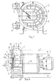
- FIG 1 is a hose pump according to the invention in one Front view along the axis of rotation of the (not visible here) Rotor shown.
- the peristaltic pump includes a pedestal 1, on which a pump housing 2 is arranged.
- the pump housing 2 in turn has an approximately circular cross-section on and is frontally bounded by a removable side wall 3.
- the side wall 3 carries a suction line 4 and a Pressure line 5 for an internal diaphragm pump.
- That behind the Sidewall 3 lying annular pump housing carries on a suction nozzle 6 and a discharge nozzle 7 for connection external lines.
- the side wall 3 is gas-tight with the annular pump housing bolted and with stiffening on the outside Ribs 8 provided.
- FIG. 2 shows the peristaltic pump shown in FIG a top view. Same components bear the same reference numbers.
- the annular pump housing 2 can be seen, that on its side wall 3 opposite side surface 10 carries a gear 11 and an electric motor 12.
- a section III the housing 3 is partially cut shown.
- rotatable rotor 14 illustrates a slider 15 carries.
- the side wall 3 carries on its inner side 16 a Diaphragm pump 17.
- the diaphragm pump 17 is via a through-bore 18 with the suction line 4 and a through hole 19 connected to the pressure line 5.
- the suction line 4 and the pressure line 5 in turn each carry a check valve 20 or 21.
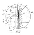
- the section III is shown enlarged in the figure 3.
- FIG. 4 shows the section according to FIG. 3 in a further enlarged and simplified representation.
- the diaphragm pump 17 is an approximately annular or dome-shaped membrane 30 made of a rubber-elastic Material has.
- the membrane 30 is in an annular Mounted holder 31 and bolted to the side wall 3.
- the membrane 30 defines an interior 32, which communicates with the through-holes 18 and 19 communicates.
- the membrane 30 carries a wear plate 33, the diaphragm 30 towards the here not shown rotor 14 substantially covers.
- the wear plate 33 is drawn on the circumference.
- the membrane 30 may be made of an elastomer be made.
- the rotor 14 may also be made of aluminum are manufactured while the slider 15 wear resistant should be interpreted, for example made of steel.
- a vacuum-resistant suction hose connected for the medium to be delivered.
- a hose extends from the suction nozzle 6 along the periphery of the housing 3 on the inside thereof to the Discharge port 7.
- a delivery hose connected for the medium to be delivered.
- the rotor 14 in the interior of the pump housing 3 is approximately bar-shaped trained and pushes the inside of the pump Hose to the annular inside of the housing 2, so that upon rotation of the rotor, that in the tube segment The rotor located medium pressed through the hose and is conveyed to the discharge nozzle 7. Behind the rotor 14 is during operation of the hose located inside the pump his own elasticity strives to expand again.
- the resulting at the suction nozzle 6 vacuum can first only be as great as the return force of the pump hose it allows.
- the pump described so far corresponds to the state of the technique.
- a vacuum is generated inside the pump, which is the automatic expansion of the pump hose on the Supported suction side.
- the diaphragm pump 17 is provided. This one will with each revolution of the pump rotor of the slider with applied to an outward force, if namely the slider 15 with the orbital motion of the rotor 14th moved past the diaphragm pump 17 over. At this moment meets the slider 15 on the wear plate 33 and pushes the Wear plate 33 and thus also the membrane 30 on the side wall 3 too.
- the interior 32 is reduced in size.
- the im Interior 32 contained gas can because of the check valve 20 does not escape through the suction line 4, but is in the pressure line 5 and through the check valve 21 in the Atmosphere pressed.
- the suction line 4 is now with its through hole 18th opposite end connected to the pump housing 2 in such a way that the line 4 with the interior of the hose pump in conjunction stands, in which the pump hose is located.
- each Operation of the diaphragm pump 17 thus promotes a part of in the interior of the pump housing 2 located gas to the outside into the atmosphere, so that over time a negative pressure in the Pump housing 2 is formed. This negative pressure is in turn desirable to the pump hose in its return movement support.
- the negative pressure in the pump housing 2 that is, where the diaphragm pump 17 is arranged, but not only supports the suction hose and thus the peristaltic pump itself during the suction process. Rather, the vacuum located in the pump housing 2 is also on the side facing away from the interior 32 of the membrane 30 and consequently also supports the membrane 30 in their Restoring movement.
- the return force of the diaphragm 30, the for between the intake 4 and the pressure line. 5 achievable pressure difference is essential, so by the supported arrangement described.
- Diaphragm pump becomes an internal pressure in this way achieved in the housing 2 in operation of about 100 mbar absolute pressure.
- the slider 15 opposite the wear plate 33 as a wear-resistant component is designed may be a maintenance of the diaphragm pump 17 thereon restrict, with removed side wall 3, the retaining ring 31, the diaphragm 30 and the wearing part 33 to replace.
- These components are relatively easy and inexpensive to manufacture. If necessary, it is also sufficient, only the membrane 30 and the wear part 33 to change. Maintenance work on the rotor 14 or the slider 15 are not in general required.
Abstract
Description
Die vorliegende Erfindung betrifft eine Schlauchpumpe mit den Merkmalen des Oberbegriffs des Anspruchs 1.The present invention relates to a peristaltic pump with the Features of the preamble of claim 1.
Schlauchpumpen sind allgemein Pumpen mit einem Pumpengehäuse, in dem ein Schlauch ringförmig entlang der Innenseite einer Gehäusewandung anliegt. Ein Rotor ist im Inneren des Pumpengehäuses vorgesehen, der durch umlaufende Quetschung des Schlauches entlang der Innenwand eine peristaltische Förderung des Schlauchinhaltes von einer Saugseite zu einer Druckseite bewirkt.Peristaltic pumps are generally pumps with a pump housing, in which a tube is annular along the inside of a Housing wall is applied. A rotor is inside the pump housing provided by circumferential squeezing of the hose along the inner wall a peristaltic promotion of the Hose content causes from a suction side to a pressure side.
An der Saugseite der Schlauchpumpe kann nur dann ein unter dem Umgebungsdruck liegender Unterdruck erzeugt werden, wenn der Schlauch innerhalb des Pumpengehäuses eine eigene Rückstellkraft entwickelt. Diese Rückstellkraft kann unterstützt werden, wenn im Pumpengehäuse ein Unterdruck aufgebaut wird. On the suction side of the peristaltic pump can only under the Ambient pressure negative pressure can be generated when the Hose within the pump housing has its own restoring force developed. This restoring force can be supported, if a vacuum is built up in the pump housing.
Aus dem Stand der Technik ist es bekannt, eine separate Unterdruckerzeugung in Form einer Pumpe mit separatem Antrieb vorzusehen oder neben dem eigentlichen Pumpenschlauch einen zweiten Schlauch anzuordnen, der saugseitig mit dem Pumpengehäuse in Verbindung steht und auf diese Weise unter der Einwirkung des Rotors das in dem Pumpengehäuse befindliche Gas aus diesem Gehäuse hinaus befördert.It is known from the prior art, a separate negative pressure generation to provide in the form of a pump with a separate drive or a second one next to the actual pump hose Hose to arrange, the suction side with the pump housing communicates and in this way under the action of the rotor located in the pump housing gas from this Housing out.
Zum einen ist diese Art der Vakuumerzeugung im Pumpengehäuse relativ aufwendig. Zum anderen kann das erzeugte Vakuum noch verbessert werden.On the one hand, this type of vacuum generation is in the pump housing relatively expensive. On the other hand, the generated vacuum can still be improved.
Es ist deshalb Aufgabe der vorliegenden Erfindung, eine Schlauchpumpe zu schaffen, bei der mit einfachen Mitteln und ohne separaten Antrieb ein Vakuum in dem Pumpengehäuse erzielt werden kann. Es ist weiter Aufgabe der Erfindung, eine Schlauchpumpe zu schaffen, die einen möglichst großen Unterdruck im Pumpengehäuse bereit stellt.It is therefore an object of the present invention, a To create peristaltic pump, using simple means and achieved a vacuum in the pump housing without a separate drive can be. It is a further object of the invention to provide a Hose pump to create the largest possible negative pressure in the pump housing provides.
Diese Aufgabe wird von einer Schlauchpumpe mit den Merkmalen des Anspruchs 1 gelöst.This task is performed by a peristaltic pump with the features of claim 1.
Weil die Mittel zur Erzeugung des Vakuums eine von dem Rotor betätigbare und in der Pumpenkammer angeordnete Membranpumpe umfassen, könnten die zur Vakuumerzeugung erforderliche Baugruppe wenige Bauteile umfassen. Wenn die Membranpumpe an der Innenseite einer Seitenwand angeordnet ist, kann sie zu Wartungszwecken mit der Seitenwand herausgenommen werden. Außerdem wird die Membran mit dem im Gehäuse befindlichen Unterdruck beaufschlagt, so dass die Rückstellkraft und damit die Saugleistung der Membranpumpe vergrößert wird.Because the means for generating the vacuum is one of the rotor operable and arranged in the pump chamber diaphragm pump include, the required for vacuum generation assembly include few components. When the diaphragm pump on the Inside a side wall is arranged, it can for maintenance purposes to be taken out with the side wall. Furthermore the membrane becomes with the negative pressure in the housing acted upon, so that the restoring force and thus the Suction capacity of the diaphragm pump is increased.
Wenn die Membranpumpe eine Membran und ein von der Membran getragenes Verschleißteil aufweist, wobei das Verschleißteil im Betrieb von einem mit dem Rotor verbundenen Gleitkörper intermittierend mit einer Kraft beaufschlagt wird, kann dieses Verschleißteil in einfacher Weise ausgewechselt werden, ohne andere Bauelemente wechseln zu müssen. Der Innenraum der Membranpumpe wird zweckmäßigerweise einerseits von dem Membran und andererseits von der Seitenwand begrenzt. Der Innenraum der Membranpumpe kann über eine Saugleitung mit der Pumpenkammer und über eine Druckleitung mit der Atmosphäre verbunden sein. Der Saugleitung und der Druckleitung sind zweckmäßigerweise die Rückschlagventile zugeordnet. Die Rückschlagventile sind für eine einfache Wartung zweckmäßig außerhalb der Pumpenkammer angeordnet.When the diaphragm pump is a diaphragm and a diaphragm carried by the diaphragm Wear part, wherein the wearing part in Operation intermittently by a slider connected to the rotor a force is applied to this wear part be easily replaced without others To change components. The interior of the diaphragm pump is expediently on the one hand by the membrane and on the other hand limited by the side wall. The interior of the Diaphragm pump can be connected to the pump chamber via a suction line and be connected via a pressure line to the atmosphere. The suction line and the pressure line are expediently associated with the check valves. The check valves are convenient for easy maintenance outside of the pump chamber arranged.
Nachfolgend wird ein Ausführungsbeispiel der vorliegenden Erfindung anhand der Zeichnung beschrieben. Es zeigen:
- Figur 1:
- eine Schlauchpumpe in einer Stirnansicht in Richtung der Drehachse des Rotors;
- Figur 2:
- eine Schlauchpumpe in einer Draufsicht;
- Figur 3:
- den Ausschnitt II aus der
Figur 2 in einer vergrößerten Darstellung; sowie - Figur 4:
- den Ausschnitt gemäß
Figur 3 in einer vereinfachten schematischen Darstellung.
- FIG. 1:
- a peristaltic pump in an end view in the direction of the axis of rotation of the rotor;
- FIG. 2:
- a peristaltic pump in a plan view;
- FIG. 3:
- the detail II of Figure 2 in an enlarged view; such as
- FIG. 4:
- the detail of Figure 3 in a simplified schematic representation.
In der Figur 1 ist eine erfindungsgemäße Schlauchpumpe in einer
Stirnansicht entlang der Drehachse des (hier nicht sichtbaren)
Rotors dargestellt. Die Schlauchpumpe umfasst einen Sockel
1, auf dem ein Pumpengehäuse 2 angeordnet ist. Das Pumpengehäuse
2 wiederum weist einen etwa kreisrunden Querschnitt
auf und ist stirnseitig von einer abnehmbaren Seitenwand 3 begrenzt.
Die Seitenwand 3 trägt eine Saugleitung 4 und eine
Druckleitung 5 für eine interne Membranpumpe. Das hinter der
Seitenwand 3 liegende ringförmige Pumpengehäuse trägt weiter
einen Saugstutzen 6 und einen Druckstutzen 7 zum Anschluss an
externe Leitungen.In the figure 1 is a hose pump according to the invention in one
Front view along the axis of rotation of the (not visible here)
Rotor shown. The peristaltic pump includes a pedestal
1, on which a
Die Seitenwand 3 ist mit dem ringförmigen Pumpengehäuse gasdicht
verschraubt und an ihrer Außenseite zur Versteifung mit
Rippen 8 versehen. The
Die Figur 2 zeigt die in Figur 1 dargestellte Schlauchpumpe in einer Draufsicht. Gleiche Bauelemente tragen gleiche Bezugsziffern.FIG. 2 shows the peristaltic pump shown in FIG a top view. Same components bear the same reference numbers.
In der Draufsicht ist das ringförmige Pumpengehäuse 2 erkennbar,
dass an seiner der Seitenwand 3 gegenüberliegenden Seitenfläche
10 ein Getriebe 11 und einen Elektromotor 12 trägt.
In einem Ausschnitt III ist das Gehäuse 3 teilweise geschnitten
dargestellt. In diesem Ausschnitt ist ein um die Drehachse
13 drehbarer Rotor 14 veranschaulicht, der einen Gleitkörper
15 trägt. Die Seitenwand 3 trägt auf ihrer Innenseite 16 eine
Membranpumpe 17. Die Membranpumpe 17 ist über eine Durchgangsbohrung
18 mit der Saugleitung 4 und über eine Durchgangsbohrung
19 mit der Druckleitung 5 verbunden. Die Saugleitung 4
und die Druckleitung 5 wiederum tragen je ein Rückschlagventil
20 bzw. 21.In the plan view, the
Der Ausschnitt III ist in der Figur 3 vergrößert dargestellt.The section III is shown enlarged in the figure 3.
Die Figur 4 zeigt den Ausschnitt gemäß Figur 3 in einer weiter vergrößerten und vereinfachten Darstellung.FIG. 4 shows the section according to FIG. 3 in a further enlarged and simplified representation.
Es ist dargestellt, dass die Membranpumpe 17 eine etwa ringförmige
oder kalottenförmige Membran 30 aus einem gummielastischen
Material aufweist. Die Membran 30 ist in einem ringförmigen
Halter 31 gelagert und mit der Seitenwand 3 verschraubt.
Die Membran 30 begrenzt einen Innenraum 32, der mit den Durchgangsbohrungen
18 und 19 kommuniziert. An ihrer dem Innenraum
32 abgewandten Außenseite trägt die Membran 30 eine Verschleißplatte
33, die die Membran 30 in Richtung auf den hier
nicht dargestellten Rotor 14 im wesentlichen abdeckt. Die Verschleißplatte
33 ist umfangsseitig abgefasst.It is shown that the
Als Material wird bei den verschiedenen Bauteilen des Pumpengehäuses
ebenso wie bei dem Verschleißelement eine Aluminiumlegierung
bevorzugt. Die Membran 30 kann aus einem Elastomer
gefertigt werden. Der Rotor 14 kann ebenfalls aus Aluminium
gefertigt werden, während der Gleitkörper 15 verschleißfest
ausgelegt werden soll, beispielsweise aus Stahl.As material is used in the various components of the pump housing
as well as the wear element an aluminum alloy
prefers. The
Im Betrieb arbeitet die ebenso weit beschriebene Schlauchpumpe wie folgt:During operation, the peristaltic pump described just as well works as follows:
An den Saugstutzen 6 wird ein unterdruckfester Saugschlauch
für das zu fördernde Medium angeschlossen. Im Inneren des Gehäuses
2 verläuft ein Schlauch von dem Saugstutzen 6 aus entlang
des Umfangs des Gehäuses 3 auf dessen Innenseite zu dem
Druckstutzen 7. An dem Druckstutzen 7 wird ebenfalls ein Förderschlauch
für das zu fördernde Medium angeschlossen. Der Rotor
14 im Inneren des Pumpengehäuses 3 ist etwa balkenförmig
ausgebildet und drückt den im Inneren der Pumpe befindlichen
Schlauch an die ringförmige Innenseite des Gehäuses 2, so dass
bei einer Drehung des Rotors das in dem Schlauchsegment vor
dem Rotor befindliche Medium durch den Schlauch gepresst und
zu dem Druckstutzen 7 gefördert wird. Hinter dem Rotor 14 wird
im Betrieb der im Inneren der Pumpe befindliche Schlauch durch
seine eigene Elastizität bestrebt sein, sich wieder auszudehnen.
Der am Saugstutzen 6 entstehende Unterdruck kann zunächst
nur so groß sein, wie die Rücksprungkraft des Pumpenschlauchs
es erlaubt.At the
Insoweit entspricht die bislang beschriebene Pumpe dem Stand der Technik.In that regard, the pump described so far corresponds to the state of the technique.
Um den Unterdruck am Saugstutzen 6 zu vergrößern ist nun vorgesehen,
dass im Pumpeninneren ein Vakuum erzeugt wird, welches
die selbsttätige Ausdehnung des Pumpenschlauchs auf der
Saugseite unterstützt. Zu diesem Zweck ist auf der Innenseite
der Seitenwand 3 die Membranpumpe 17 vorgesehen. Diese wird
bei jeder Umdrehung des Pumpenrotors von dem Gleitkörper mit
einer nach außen wirkenden Kraft beaufschlagt, wenn nämlich
der Gleitkörper 15 sich mit der Umlaufbewegung des Rotors 14
an der Membranpumpe 17 vorbei bewegt. In diesem Moment trifft
der Gleitkörper 15 auf die Verschleißplatte 33 und drückt die
Verschleißplatte 33 und damit auch die Membran 30 auf die Seitenwand
3 zu. Der Innenraum 32 wird dabei verkleinert. Das im
Innenraum 32 enthaltene Gas kann wegen des Rückschlagventils
20 nicht durch die Saugleitung 4 entweichen, sondern wird in
die Druckleitung 5 und durch das Rückschlagventil 21 in die
Atmosphäre gedrückt.In order to increase the negative pressure at the
Sobald der Gleitkörper 15 die Verschleißplatte 33 wieder frei
gibt, wird durch die Rückstellkraft der Membran 30 der Innenraum
32 der Membranpumpe 17 wieder vergrößert. Der entstehende
Unterdruck saugt das in der Saugleitung 4 vorhandene Gasvolumen
durch das in dieser Richtung öffnende Rückschlagventil 20
in den Innenraum der Membranpumpe 32. Bei der nächsten Umdrehung
des Rotors 14 wiederholt sich dieser Vorgang.Once the
Die Saugleitung 4 ist nun mit ihrem der Durchgangsbohrung 18
abgewandten Ende mit dem Pumpengehäuse 2 derart verbunden,
dass die Leitung 4 mit dem Innenraum der Schlauchpumpe in Verbindung
steht, in dem sich der Pumpenschlauch befindet. Jede
Betätigung der Membranpumpe 17 fördert folglich einen Teil des
im Innenraum des Pumpengehäuses 2 befindlichen Gases nach Außen
in die Atmosphäre, so dass mit der Zeit ein Unterdruck im
Pumpengehäuse 2 entsteht. Dieser Unterdruck wiederum ist erwünscht,
um den Pumpenschlauch in seiner Rückstellbewegung zu
unterstützen.The
Der Unterdruck im Pumpengehäuse 2, also dort, wo die Membranpumpe
17 angeordnet ist, unterstütz aber nicht nur den Saugschlauch
und damit die Schlauchpumpe selbst bei dem Saugvorgang.
Vielmehr steht der im Pumpengehäuse 2 befindliche Unterdruck
auch an der dem Innenraum 32 abgewandten Seite der Membran
30 an und unterstützt folglich auch die Membran 30 in ihrer
Rückstellbewegung. Die Rücksprungkraft der Membran 30, die
für die zwischen der Ansaugleitung 4 und der Druckleitung 5
erreichbare Druckdifferenz wesentlich ist, wird also durch die
beschriebene Anordnung unterstützt.The negative pressure in the
In der Praxis bedeutet dies, dass der Schließdruck des Rückschlagventils
20 von der Rückstellkraft der Membran 30 überwunden
werden muss, nicht aber ein zusätzlicher, auf der Membran
lastender atmosphärischer Druck. Bei der insoweit beschriebenen
Membranpumpe wird auf diese Weise ein Innendruck
im Gehäuse 2 im Betrieb von etwa 100 mbar absolut Druck erreicht.In practice, this means that the closing pressure of the
Ein großer Vorteil der insoweit beschriebenen Anordnung besteht
in der einfachen Wartung. Da der Gleitkörper 15 gegenüber
der Verschleißplatte 33 als verschleißfestes Bauelement
ausgelegt ist, kann sich eine Wartung der Membranpumpe 17 darauf
beschränken, bei abgenommener Seitenwand 3 den Haltering
31, die Membran 30 und das Verschleißteil 33 auszuwechseln.
Diese Bauelemente sind relativ einfach und preiswert zu fertigen.
Gegebenenfalls ist es auch ausreichend, nur die Membran
30 und das Verschleißteil 33 zu wechseln. Wartungsarbeiten an
dem Rotor 14 oder dem Gleitkörper 15 sind im allgemeinen nicht
erforderlich.A great advantage of the arrangement described so far is
in easy maintenance. Since the
Es handelt sich also bei der vorliegenden Erfindung um eine
Schlauchpumpe mit einer ausgesprochen einfachen und zuverlässigen
Vorrichtung zur Erzeugung eines niedrigen Innendrucks in
dem Pumpengehäuse 2.So it is in the present invention is a
Peristaltic pump with a decidedly simple and reliable
Device for generating a low internal pressure in
the
Claims (7)
Applications Claiming Priority (2)
| Application Number | Priority Date | Filing Date | Title |
|---|---|---|---|
| DE10357320A DE10357320A1 (en) | 2003-12-05 | 2003-12-05 | Peristaltic pump with vacuum generation device |
| DE10357320 | 2003-12-05 |
Publications (3)
| Publication Number | Publication Date |
|---|---|
| EP1538335A2 true EP1538335A2 (en) | 2005-06-08 |
| EP1538335A3 EP1538335A3 (en) | 2006-01-11 |
| EP1538335B1 EP1538335B1 (en) | 2008-09-03 |
Family
ID=34442501
Family Applications (1)
| Application Number | Title | Priority Date | Filing Date |
|---|---|---|---|
| EP04026512A Expired - Fee Related EP1538335B1 (en) | 2003-12-05 | 2004-11-09 | Peristaltic pump with a vacum generating device |
Country Status (4)
| Country | Link |
|---|---|
| EP (1) | EP1538335B1 (en) |
| AT (1) | ATE407293T1 (en) |
| DE (1) | DE10357320A1 (en) |
| ES (1) | ES2312903T3 (en) |
Families Citing this family (1)
| Publication number | Priority date | Publication date | Assignee | Title |
|---|---|---|---|---|
| CN110735782B (en) * | 2019-07-22 | 2021-04-16 | 六安永贞匠道机电科技有限公司 | Flexible pneumatic driving method of diaphragm pump |
Citations (3)
| Publication number | Priority date | Publication date | Assignee | Title |
|---|---|---|---|---|
| US4375346A (en) * | 1979-03-29 | 1983-03-01 | A. T. Ramot Plastics Ltd. | Diaphragm pump |
| US5342182A (en) * | 1992-02-25 | 1994-08-30 | The Regents Of The University Of Michigan | Self regulating blood pump with controlled suction |
| WO1998042401A1 (en) * | 1997-03-24 | 1998-10-01 | Michael Goldberg | Vacuum assisted peristaltic pumping |
Family Cites Families (3)
| Publication number | Priority date | Publication date | Assignee | Title |
|---|---|---|---|---|
| DE3703124A1 (en) * | 1987-02-03 | 1988-08-11 | Manfred Streicher | HOSE PUMP |
| DE4303319A1 (en) * | 1993-02-05 | 1994-08-11 | Putzmeister Maschf | Vacuum pumping device |
| DE19940498A1 (en) * | 1999-08-26 | 2001-03-22 | Knf Neuberger Gmbh | Diaphragm pump |
-
2003
- 2003-12-05 DE DE10357320A patent/DE10357320A1/en not_active Withdrawn
-
2004
- 2004-11-09 ES ES04026512T patent/ES2312903T3/en active Active
- 2004-11-09 EP EP04026512A patent/EP1538335B1/en not_active Expired - Fee Related
- 2004-11-09 AT AT04026512T patent/ATE407293T1/en active
Patent Citations (3)
| Publication number | Priority date | Publication date | Assignee | Title |
|---|---|---|---|---|
| US4375346A (en) * | 1979-03-29 | 1983-03-01 | A. T. Ramot Plastics Ltd. | Diaphragm pump |
| US5342182A (en) * | 1992-02-25 | 1994-08-30 | The Regents Of The University Of Michigan | Self regulating blood pump with controlled suction |
| WO1998042401A1 (en) * | 1997-03-24 | 1998-10-01 | Michael Goldberg | Vacuum assisted peristaltic pumping |
Also Published As
| Publication number | Publication date |
|---|---|
| EP1538335A3 (en) | 2006-01-11 |
| DE10357320A1 (en) | 2005-06-30 |
| ES2312903T3 (en) | 2009-03-01 |
| ATE407293T1 (en) | 2008-09-15 |
| EP1538335B1 (en) | 2008-09-03 |
Similar Documents
| Publication | Publication Date | Title |
|---|---|---|
| EP0800836B1 (en) | Breast pump | |
| DE1628144C3 (en) | Suction throttle control device | |
| EP2761180A2 (en) | Positive displacement pump and operating method thereof | |
| DE2750350C2 (en) | ||
| WO2005083267A1 (en) | Viscous matter piston pump | |
| EP0626516A1 (en) | Two stage positive displacement pump | |
| DE20303854U1 (en) | Electric and multifunctional massage device for weight loss and fitness | |
| EP0620898A1 (en) | Compact controllable vane pump. | |
| EP1169572B1 (en) | Piston vacuum pump with a gas inlet and a gas outlet | |
| DE1703528C3 (en) | Control device for a multi-stage swash plate axial piston and swash piston machine set | |
| DE1403954C3 (en) | Compressor for pumping gas | |
| DE3042328A1 (en) | PISTON PUMP | |
| DE102007010729B3 (en) | Vacuum pump for use in engine of motor vehicle, has sealing body flexibly designed and fixed at air discharge opening at front and rear ends of opening in rotation direction of rotor, where body lies permanently at opening | |
| DE102004056744A1 (en) | fluid compressor | |
| DE3005834C2 (en) | ||
| EP1538335A2 (en) | Peristaltic pump with a vacum generating device | |
| DE4443387C1 (en) | Twin=step mechanical vacuum pump assembly | |
| DE1628271C3 (en) | Multi-stage liquid ring compressor or multi-stage liquid ring pump | |
| EP0682751A1 (en) | Vacuum pump device. | |
| DE102008013335A1 (en) | Vane cell machine for use as e.g. vane cell pump to convey liquid into common pipe line, has hollow rotor with rotor slots for vane, and outer chambers and inner chambers provided with inlets and outlets | |
| DD269881A1 (en) | PISTON COMPRESSOR | |
| DE2910328A1 (en) | Bellows type oil filled pump - has valve on rod inside bellows to prevent accumulation of air bubbles in oil inside bellows | |
| DE3210240A1 (en) | Diaphragm displacement pump | |
| DE962498C (en) | Diaphragm pump | |
| DE1528895A1 (en) | centrifugal pump |
Legal Events
| Date | Code | Title | Description |
|---|---|---|---|
| PUAI | Public reference made under article 153(3) epc to a published international application that has entered the european phase |
Free format text: ORIGINAL CODE: 0009012 |
|
| AK | Designated contracting states |
Kind code of ref document: A2 Designated state(s): AT BE BG CH CY CZ DE DK EE ES FI FR GB GR HU IE IS IT LI LU MC NL PL PT RO SE SI SK TR |
|
| AX | Request for extension of the european patent |
Extension state: AL HR LT LV MK YU |
|
| PUAL | Search report despatched |
Free format text: ORIGINAL CODE: 0009013 |
|
| AK | Designated contracting states |
Kind code of ref document: A3 Designated state(s): AT BE BG CH CY CZ DE DK EE ES FI FR GB GR HU IE IS IT LI LU MC NL PL PT RO SE SI SK TR |
|
| AX | Request for extension of the european patent |
Extension state: AL HR LT LV MK YU |
|
| RIC1 | Information provided on ipc code assigned before grant |
Ipc: F04B 23/04 20060101ALI20051121BHEP Ipc: F04B 43/02 20060101AFI20050304BHEP Ipc: F04B 43/067 20060101ALI20051121BHEP |
|
| 17P | Request for examination filed |
Effective date: 20060411 |
|
| AKX | Designation fees paid |
Designated state(s): AT ES FR GB IT NL |
|
| REG | Reference to a national code |
Ref country code: DE Ref legal event code: 8566 |
|
| 17Q | First examination report despatched |
Effective date: 20070613 |
|
| GRAP | Despatch of communication of intention to grant a patent |
Free format text: ORIGINAL CODE: EPIDOSNIGR1 |
|
| GRAS | Grant fee paid |
Free format text: ORIGINAL CODE: EPIDOSNIGR3 |
|
| GRAA | (expected) grant |
Free format text: ORIGINAL CODE: 0009210 |
|
| AK | Designated contracting states |
Kind code of ref document: B1 Designated state(s): AT ES FR GB IT NL |
|
| REG | Reference to a national code |
Ref country code: GB Ref legal event code: FG4D Free format text: NOT ENGLISH |
|
| REG | Reference to a national code |
Ref country code: ES Ref legal event code: FG2A Ref document number: 2312903 Country of ref document: ES Kind code of ref document: T3 |
|
| PLBE | No opposition filed within time limit |
Free format text: ORIGINAL CODE: 0009261 |
|
| STAA | Information on the status of an ep patent application or granted ep patent |
Free format text: STATUS: NO OPPOSITION FILED WITHIN TIME LIMIT |
|
| 26N | No opposition filed |
Effective date: 20090604 |
|
| PGFP | Annual fee paid to national office [announced via postgrant information from national office to epo] |
Ref country code: FR Payment date: 20110510 Year of fee payment: 7 Ref country code: ES Payment date: 20110426 Year of fee payment: 7 |
|
| PGFP | Annual fee paid to national office [announced via postgrant information from national office to epo] |
Ref country code: AT Payment date: 20110426 Year of fee payment: 7 Ref country code: GB Payment date: 20110420 Year of fee payment: 7 Ref country code: NL Payment date: 20110503 Year of fee payment: 7 |
|
| PGFP | Annual fee paid to national office [announced via postgrant information from national office to epo] |
Ref country code: IT Payment date: 20110429 Year of fee payment: 7 |
|
| REG | Reference to a national code |
Ref country code: NL Ref legal event code: V1 Effective date: 20120601 |
|
| GBPC | Gb: european patent ceased through non-payment of renewal fee |
Effective date: 20111109 |
|
| PG25 | Lapsed in a contracting state [announced via postgrant information from national office to epo] |
Ref country code: NL Free format text: LAPSE BECAUSE OF NON-PAYMENT OF DUE FEES Effective date: 20120601 |
|
| REG | Reference to a national code |
Ref country code: FR Ref legal event code: ST Effective date: 20120731 |
|
| PG25 | Lapsed in a contracting state [announced via postgrant information from national office to epo] |
Ref country code: IT Free format text: LAPSE BECAUSE OF NON-PAYMENT OF DUE FEES Effective date: 20111109 |
|
| PG25 | Lapsed in a contracting state [announced via postgrant information from national office to epo] |
Ref country code: GB Free format text: LAPSE BECAUSE OF NON-PAYMENT OF DUE FEES Effective date: 20111109 |
|
| REG | Reference to a national code |
Ref country code: AT Ref legal event code: MM01 Ref document number: 407293 Country of ref document: AT Kind code of ref document: T Effective date: 20111109 |
|
| PG25 | Lapsed in a contracting state [announced via postgrant information from national office to epo] |
Ref country code: FR Free format text: LAPSE BECAUSE OF NON-PAYMENT OF DUE FEES Effective date: 20111130 |
|
| PG25 | Lapsed in a contracting state [announced via postgrant information from national office to epo] |
Ref country code: AT Free format text: LAPSE BECAUSE OF NON-PAYMENT OF DUE FEES Effective date: 20111109 |
|
| REG | Reference to a national code |
Ref country code: ES Ref legal event code: FD2A Effective date: 20130603 |
|
| PG25 | Lapsed in a contracting state [announced via postgrant information from national office to epo] |
Ref country code: ES Free format text: LAPSE BECAUSE OF NON-PAYMENT OF DUE FEES Effective date: 20111110 |