EP1538285A2 - Re-keyable lock and method - Google Patents
Re-keyable lock and method Download PDFInfo
- Publication number
- EP1538285A2 EP1538285A2 EP04027698A EP04027698A EP1538285A2 EP 1538285 A2 EP1538285 A2 EP 1538285A2 EP 04027698 A EP04027698 A EP 04027698A EP 04027698 A EP04027698 A EP 04027698A EP 1538285 A2 EP1538285 A2 EP 1538285A2
- Authority
- EP
- European Patent Office
- Prior art keywords
- lock
- keying
- wafer
- rider
- cylinder
- Prior art date
- Legal status (The legal status is an assumption and is not a legal conclusion. Google has not performed a legal analysis and makes no representation as to the accuracy of the status listed.)
- Granted
Links
Images




Classifications
-
- E—FIXED CONSTRUCTIONS
- E05—LOCKS; KEYS; WINDOW OR DOOR FITTINGS; SAFES
- E05B—LOCKS; ACCESSORIES THEREFOR; HANDCUFFS
- E05B29/00—Cylinder locks and other locks with plate tumblers which are set by pushing the key in
- E05B29/004—Cylinder locks and other locks with plate tumblers which are set by pushing the key in with changeable combinations
-
- Y—GENERAL TAGGING OF NEW TECHNOLOGICAL DEVELOPMENTS; GENERAL TAGGING OF CROSS-SECTIONAL TECHNOLOGIES SPANNING OVER SEVERAL SECTIONS OF THE IPC; TECHNICAL SUBJECTS COVERED BY FORMER USPC CROSS-REFERENCE ART COLLECTIONS [XRACs] AND DIGESTS
- Y10—TECHNICAL SUBJECTS COVERED BY FORMER USPC
- Y10T—TECHNICAL SUBJECTS COVERED BY FORMER US CLASSIFICATION
- Y10T70/00—Locks
- Y10T70/70—Operating mechanism
- Y10T70/7441—Key
- Y10T70/7486—Single key
- Y10T70/7508—Tumbler type
- Y10T70/7559—Cylinder type
- Y10T70/7588—Rotary plug
- Y10T70/7593—Sliding tumblers
- Y10T70/7599—Transverse of plug
-
- Y—GENERAL TAGGING OF NEW TECHNOLOGICAL DEVELOPMENTS; GENERAL TAGGING OF CROSS-SECTIONAL TECHNOLOGIES SPANNING OVER SEVERAL SECTIONS OF THE IPC; TECHNICAL SUBJECTS COVERED BY FORMER USPC CROSS-REFERENCE ART COLLECTIONS [XRACs] AND DIGESTS
- Y10—TECHNICAL SUBJECTS COVERED BY FORMER USPC
- Y10T—TECHNICAL SUBJECTS COVERED BY FORMER US CLASSIFICATION
- Y10T70/00—Locks
- Y10T70/70—Operating mechanism
- Y10T70/7441—Key
- Y10T70/7486—Single key
- Y10T70/7508—Tumbler type
- Y10T70/7559—Cylinder type
- Y10T70/7588—Rotary plug
- Y10T70/7593—Sliding tumblers
- Y10T70/7599—Transverse of plug
- Y10T70/7616—Including sidebar
-
- Y—GENERAL TAGGING OF NEW TECHNOLOGICAL DEVELOPMENTS; GENERAL TAGGING OF CROSS-SECTIONAL TECHNOLOGIES SPANNING OVER SEVERAL SECTIONS OF THE IPC; TECHNICAL SUBJECTS COVERED BY FORMER USPC CROSS-REFERENCE ART COLLECTIONS [XRACs] AND DIGESTS
- Y10—TECHNICAL SUBJECTS COVERED BY FORMER USPC
- Y10T—TECHNICAL SUBJECTS COVERED BY FORMER US CLASSIFICATION
- Y10T70/00—Locks
- Y10T70/70—Operating mechanism
- Y10T70/7441—Key
- Y10T70/7486—Single key
- Y10T70/7508—Tumbler type
- Y10T70/7559—Cylinder type
- Y10T70/7667—Operating elements, parts and adjuncts
- Y10T70/7689—Tumblers
- Y10T70/7695—Plate
-
- Y—GENERAL TAGGING OF NEW TECHNOLOGICAL DEVELOPMENTS; GENERAL TAGGING OF CROSS-SECTIONAL TECHNOLOGIES SPANNING OVER SEVERAL SECTIONS OF THE IPC; TECHNICAL SUBJECTS COVERED BY FORMER USPC CROSS-REFERENCE ART COLLECTIONS [XRACs] AND DIGESTS
- Y10—TECHNICAL SUBJECTS COVERED BY FORMER USPC
- Y10T—TECHNICAL SUBJECTS COVERED BY FORMER US CLASSIFICATION
- Y10T70/00—Locks
- Y10T70/70—Operating mechanism
- Y10T70/7441—Key
- Y10T70/7729—Permutation
- Y10T70/774—Adjustable tumblers
-
- Y—GENERAL TAGGING OF NEW TECHNOLOGICAL DEVELOPMENTS; GENERAL TAGGING OF CROSS-SECTIONAL TECHNOLOGIES SPANNING OVER SEVERAL SECTIONS OF THE IPC; TECHNICAL SUBJECTS COVERED BY FORMER USPC CROSS-REFERENCE ART COLLECTIONS [XRACs] AND DIGESTS
- Y10—TECHNICAL SUBJECTS COVERED BY FORMER USPC
- Y10T—TECHNICAL SUBJECTS COVERED BY FORMER US CLASSIFICATION
- Y10T70/00—Locks
- Y10T70/70—Operating mechanism
- Y10T70/7441—Key
- Y10T70/7915—Tampering prevention or attack defeating
- Y10T70/7932—Anti-pick
Definitions
- pin-tumbler cylinder locks or wafer-tumbler cylinder locks.
- Each of these locks contains a cylinder or plug which rotates within a housing or shell.
- pin holes containing top and bottom pin tumblers extend transversely through both the cylinder and the housing, and may be crossing the shear line, i.e. the boundary between the cylinder and the housing.
- the pin tumblers slide up and down within the pin holes defining a locked position and an unlocked position. When a pin tumbler crosses the shear line, the pin tumbler interferes with the rotation of the cylinder and the cylinder remains locked.
- the bitting on the key contact the pin tumblers and force them to slide within their pin holes such that no pin crosses the shear line.
- the cylinder can then rotate within the housing when a torque is applied by the key to unlock the lock.
- Wafer-tumbler locks have wafer-shaped tumblers which slide up and down within channels that extend from the cylinder to the housing.
- the wafer tumblers are spring loaded so that they can extend out of the cylinder and into a locking slot within the housing, thereby preventing rotation of the cylinder relative to the housing in a locked position.
- the center of each of the wafer tumblers has an opening for receiving a key. The correct key moves the wafer tumblers out of the locking slot, such that torque applied to the cylinder rotates the cylinder within the housing and unlocks of the lock.
- the lock has locked and unlocked positions and may include a housing and a cylinder rotatably supported in the housing and having a plurality of channels.
- the lock includes a plurality of wafer tumblers resiliently supported in the corresponding channels. Each wafer tumbler has a rider element selectively engaged with a base element in first and second engagement positions, wherein the first engagement position corresponds to a first key and the second engagement position corresponds to a second key.
- the lock also includes a re-keying slot on a face of the cylinder such that a re-keying tool can be inserted in the slot when the cylinder is in a learn position to disengage each rider element from the corresponding base element in the first engagement position to enable re-engaging the rider element to the base element in the second engagement position. In this manner, the lock may be re-keyed without disassembly of the cylinder assembly.
- FIG. 1 is an exploded perspective view of an embodiment of a lock according to the present invention
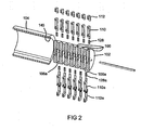
- FIG. 2 is a exploded perspective view of a longitudinal section of the lock of FIG. 1;
- FIG. 3 is an assembled perspective view of a longitudinal section of the lock of FIG. 1;
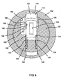
- FIG. 4 is a sectional view of the lock showing an embodiment of a first wafer tumbler in a locked and engaged position
- FIG. 5 is a sectional view of the lock showing the first wafer tumbler of FIG. 4 in an unlocked and disengaged position;
- FIG 6 is a sectional view of the lock showing an embodiment of a second wafer tumbler in a locked and engaged position
- FIG. 7 is a sectional view of the lock showing the second wafer tumbler of FIG. 6 in an unlocked and disengaged position.
- FIG. 1 is an exploded view of an embodiment of a re-keyable lock 100 according to the invention.
- the lock 100 includes a cylinder 102, which rotates in a housing 104.
- the cylinder 102 has a plurality of first channels 106 as best see in FIGS. 2 and 4.
- the first channels 106 are sized to receive a first set of wafer tumblers 108.
- Each first wafer tumbler 108 includes a base element 110 and a rider element 112.
- each base element 110 is a substantially flat plate that has an opening 114 that allows a key 120 to be inserted into the lock 100.
- the base element 110 may have a lower portion 122, which may be U-shaped and have two legs 124 as best seen in FIG. 4.
- the legs 124 may be received in corresponding cavities 126 that extend from the corresponding first channel 106.
- the base element 110 is resiliently supported in the corresponding first channel 106 by any resilient mechanism, such as, for example, by two springs or coils 128 that are received in the cavities 126.
- the springs 128 bias the base element 110 toward the housing 104 and away from the cavities 126 to a "locked position", shown in FIG. 4, in which the cylinder 102 cannot turn relative to the housing 104, as is explained below.
- Each base element 110 includes a plurality of engagement formations, such as slots or tabs, 130.
- Each rider element 112 may have an open frame that is supported on a corresponding base element 110 .
- the rider element 112 includes a top portion 134, an engagement arm 136, and a support arm 138.
- the engagement arm 136 includes one or more engagement formations, such as tabs or slots, 132, that are engagable with one of the engagement formations 130 of the base element 110.
- the support arm 138 may contact a portion of the base element 110 providing additional stability for the rider element 112.
- the top portion 134 of the rider element 112 may be biased by the spring-loaded base element 110 into a locking slot 140 in the housing 104, thereby locking the lock 100 and preventing the cylinder 102 from rotating relative to the housing 104.
- the locking slot 140 is appropriately sized and shaped to receive the upper portion 134 of the rider element 112 in the locked position.
- the engagement slots 130 of the base element 110 are spaced at distances that correspond to standard sizes of bitting 133 in the key 120.
- the sequence of bitting sizes determines the proper key for a lock.
- each bitting size is designated by an integer number.
- a sequence of seven digits determines the locking combination of the key.
- the sequence "1212121”, for example, includes three bittings of size 2 and four bitting of size 1.
- each wafer tumbler 108 may assume any one of six positions corresponding to six different bitting numbers.
- each first wafer tumbler 108 may assume any one of five positions corresponding to five different bitting numbers.
- the rider element 112 is provided with three engagement tabs 132 for the six engagement slots 130 of the base element 110, and therefore the first wafer tumblers 108 for this embodiment may assume any one of four positions corresponding to four different bitting numbers.
- the number of different bitting numbers available for each wafer tumbler 108 is determined by the number of available positions in which the engagement tabs 132 can be placed into the engagement slots 130. Assuming that the number of slots N2 is greater than the number of tabs N1, the number of available positions equals N2-N1+1.
- the shapes of the engagement tabs 132 and the engagement slots 132 do not have to be rectangular, as is shown in the embodiment of FIG. 4. Other shapes, including curves and straight lines may also be used. Furthermore, the placement of the engagement tabs 132 and engagement slots 130 may be interchanged, i.e., the engagement tabs 132 may be placed in the base element 110 and engagement slots 130 may be placed in the rider element 112. A periodic pattern of tabs 132 alternating with slots 130 may also be used in both the engagement arm 136 and the base element 110, as shown in FIG. 4.
- the engagement arm 136 is a flexible element that includes a flange 142 extending from an end 144 that is adjacent to the tabs 132. By exerting a force against the flange 142, the engagement tabs 132 of the rider element 112 may be disengaged from the engagement slots 130 of the base element 110 to allow re-keying the lock 100 as is described below.
- the cylinder 102 includes a face 146 having a keyway 148 and a re-keying slot 150.
- the re-keying slot 150 may be sized to receive a re-keying tool 152.
- the re-keying tool 152 is a long rod, which, when inserted into the re-keying slot 150, pushes against the flange 146 and the base element 110 causing the engagement arm 136 to deflect, and thereby prying the engagement tabs 132 out of the engagement slots 130.
- the re-keying slot 150 may be positioned relative to cylinder 102 such that the re-keying tool 152 may engage the flange 142 when the original correct key 120 is inserted in the keyway 148 to rotate the cylinder 102 into an position as shown in FIG. 5.
- each wafer tumbler 108 may be completely received in the corresponding first cylinder channel 106, i.e. all the top portions 136 are disengaged from and are out of the first locking slot 140 of the housing 104, such that there is no interference in the rotation of the cylinder 102 relative to the housing 104.
- the re-keying slot 150 may have, for example, a T-shaped cross-section and the tool 152 may also have a T-shaped cross-section.
- the flange 154 of the tool 152 may push against base element 110, while the web 156 of the tool 152 pushes against the flange 142 of the rider element 112, thereby disengaging the rider element 112 from the base element 110.
- the re-keying tool 152 is preferably tapered along its length to facilitate disengagement of the rider elements 112 from the base elements 110. While the present invention has been described with reference to a re-keying tool which is separable from the lock 100, one skilled in the art will recognize that similar structure which is integral with the lock could be utilized to provide the described re-keying function.
- the lock 100 is re-keyed by the following procedure. Initially, the rider elements 112 are engaged with the base elements 110 in a first engagement position that corresponds to a first key 120, e.g., the original unlocking key 120, as shown in FIG. 4. The first key 120 is inserted in the keyway 148 and the cylinder 102 is rotated to unlock the lock 100 as shown in FIG. 4, thereby placing the lock 100 in a learn mode. In this state, the lock 100 may be re-keyed by insert in the re-keying tool 152 in the re-keying slot 150 such that the engagement arm 136 of the rider element 112 is disengaged from the base element 110. The first key 120 can be removed and a second key inserted in the keyway 148. The tool 152 is then removed, forcing the rider elements 112 to engage the base elements 104 in a second engagement position that is determined by the bitting 133 of the second key, thereby re-keying the lock 100 for the second key.
- the lock 100 includes a second set of wafer tumblers 108a received in corresponding second channels 106a in the cylinder 102.
- the second wafer tumblers 108a are similar to first wafer tumblers 108 described above and thus their description will not be repeated. Elements of the second wafer tumblers 108a corresponding to similar elements of the first wafer tumblers 108 are indicated by the same reference numbers followed by the letter "a".
- each second wafer tumbler 108a may include a rider element 112a and a base element 110a, etc.
- the second channels 106a are interlaced with the first channels 106 and the first and second wafer tumblers 108, 108a are positioned such that the engagement arms 136, 136a are on opposite sides relative to the keyway 148 of the lock 100.
- seven first wafer tumblers 108 and six second wafer tumblers 108a are shown in the embodiment of FIG. 1.
- the number and location of water tumblers in a given lock may vary depending on the requirements of the particular application.
- the rider elements 112a of the second wafer tumblers 108a are disengaged from the corresponding base elements 110a by inserting a second re-keying tool 152a through a second re-keying slot 150a on the face 146 of the cylinder 102 in the unlocked position as seen in FIGS. 6 and 7.
- the engagement positions of the second rider elements 112a on the second base elements 110a are not dictated by, and thus are independent of the engagement positions of the rider elements 112 on the base elements 110.
- the unlocking keys may have either symmetric or non-symmetric bitting 133.
- first and second base elements 110, 110a and the first and second rider elements 112, 112a may have tapered thickness to facilitate inserting the key 120 in the openings 114,114a of the first and second base elements, respectively, and inserting the re-keying tools 152, 152a in the corresponding re-keying slots 150, 150a as best seen in FIGS. 4-7.
- the invention provides a versatile, cost-effective and convenient re-keyable lock 100.
- Many combinations of first and second wafer tumblers 108, 108a are possible.
- Many sequences of engagement formations 130, 132 are also available and may be selected for each wafer tumbler 108, 108a. Therefore, a great number of new keys may be provided for re-keying the same lock 100 without ever having to disassemble it.
Landscapes
- Physics & Mathematics (AREA)
- Electromagnetism (AREA)
- Lock And Its Accessories (AREA)
- Quick-Acting Or Multi-Walled Pipe Joints (AREA)
- Connection Of Plates (AREA)
- Input From Keyboards Or The Like (AREA)
- Preventing Unauthorised Actuation Of Valves (AREA)
Abstract
Description
Claims (33)
- A re-keyable lock comprising:a cylinder rotatably supported in a housing between a locked position and an unlocked position, said cylinder having a longitudinal slot and one or more transverse channels;a locking mechanism including one or more wafer tumblers resiliently supported in said transverse channel and positionable therein between an engaged position wherein said wafer tumbler engages said housing and a disengaged position wherein said wafer tumbler disengages said housing, said wafer tumbler including a base element having an opening formed therethrough which is at least partially aligned with said longitudinal slot, a rider element positionable within said transverse channel relative to said base element and a coupling element optionally integral with the rider element and positionable between a first position wherein said base element is coupled to said rider element and a second position wherein said base element is uncoupled from said rider element; anda re-keying mechanism operable when said cylinder is in said unlocked position to move said coupling element from said first position to said second position for repositioning said rider element relative to said base element such that the lock is re-keyed.
- The lock of claim 1, wherein said coupling element comprises a flexible element biased to couple said base element and said rider element, said flexible element being deflectable to uncouple said base element and said rider element.
- The lock of claim 1 or claim 2, wherein said rider element selectively engages a plurality of engagement formations in said base element, each of said plurality of engagement formations corresponding to a bitting size.
- The lock of claim 3, wherein each of said plurality of engagement formations comprise a tab, or a slot..
- The lock of any of the preceding claims wherein said re-keying mechanism comprises a re-keying tool insertable into a re-keying slot formed in said cylinder to deflect said flexible element.
- The lock of claim 5 , wherein said re-keying slot is T-shaped, or tapered.
- The lock of any of the preceding claims, wherein said base element comprises a body portion and a pair of legs extending therefrom, said pair of legs being received in a mating portion of said transverse channel.
- The lock of claim 7 further comprising a pair of springs disposed in said mating portion of said transverse channel and engaging said pair of legs to bias said locking mechanism into said engaged position.
- The lock of any of the claims 7 or 8, wherein said rider element comprises a pair of arms, said pair of arms capturing said first body portion therebetween.
- The lock of any of the preceding claims , wherein said locking mechanism further comprises a plurality of wafer tumblers, each of said plurality of wafer tumblers resiliently supported in one of a plurality of transverse channels formed in said cylinder.
- A re-keyable lock according to any of the preceding claims, further comprising:a first set of transverse channels and a second set of transverse channels opposingly interlaced with said first set of transverse channels whereby a first set of wafer tumblers is resiliently supported in said first set of transverse channels; and a set of second wafer tumblers is resiliently supported in said second set of transverse channels, each wafer tumbler of said first and second sets of wafer tumblers including a base element having an opening formed therethrough which is at least partially aligned with said longitudinal slot.
- A re-keyable lock according to any of the preceding claims wherein the cylinder is rotatably supported in a housing, said cylinder having a longitudinal slot and a plurality of transverse channels and wherein the locking mechanism is positionable between an unlocked position and a locked position, the locking mechanism including a plurality of the wafer tumblers resiliently supported in a corresponding one of the plurality of transverse channels, each of said plurality of wafer tumblers including a rider element selectively engagable with a base element in a first engagement position corresponding to a first key and a second engagement position corresponding to a second key; the re-keying mechanism comprising a a re-keying tool being insertable in a re-keying slot centrally offset from the longitudinal key slot, the re-keying tool operable when said locking mechanism is in said unlocked position to disengage each rider element from each base element in said first engagement position and engage each rider element to each base element in said second engagement position.
- The lock of claim 12, wherein each of said plurality of wafer tumblers includes a first set of wafer tumblers opposingly interlaced with a second set of wafer tumblers.
- The lock of claim 12 or 13 wherein said re-keying tool is associated with said first set of wafer tumblers and a second re-keying tool associated with said second set of wafer tumblers.
- A method for in-situ re-keying of a lock, the method comprising:inserting a first key into a key hole of a lock cylinder;rotating said lock cylinder relative to a housing with said first key to put the lock into a learn position; accessing a re-keying slot, preferably by inserting a re-keying tool, of the lock cylinder, the re-keying slot being centrally offset from the key hole; uncoupling a first element of a wafer tumbler from a second element of said wafer tumbler; replacing said first key with a second key such that said first element is re-positioned relative to said second element; coupling said first element to said second element of said wafer tumbler; rotating said lock cylinder to a locked position with said second key; and removing said second key.
- The method of claim 15, wherein coupling includes biasing a flexible element interposed between said first element and said second element to couple said first element to said second element.
- The method of claim 15 or 16, wherein uncoupling includes deflecting said flexible element to uncouple said first element from said second element.
- The method of claim 17, wherein coupling includes removing said re-keying tool from said re-keying slot.
- A re-keyable lock according to any of the claims 1-14, wherein the re-keying mechanism comprises a removable re-keying tool insertable into a re-keying slot formed in said cylinder between said coupling element and said base to deflect said flexible element, the re-keying tool being operable when said cylinder is in said unlocked position to move the coupling element from the first position to the second position for repositioning the rider element relative to the base element such that the key is re-keyed.
- The lock according to claim 19, wherein the re-keying slot is centrally offset from the longitudinal key slot.
- The re-keyable lock of any of the preceding claims 1-14, 19 or 20, wherein the re-keying mechanism comprises a re-keying element postionable relative to the wafer tumbler within the cylinder to engage the coupling element.
- A re-keyable lock comprising; a cylinder rotatably supported in a housing having a longitudinal key slot and a transverse channel; a locking mechanism positionable between an unlocked position and a locked position, the locking mechanism including a wafer tumbler resiliently supported in the transverse channel, the wafer tumbler including a rider element selectively engagable with a base element in a first engagement position corresponding to a first key and a second engagement position corresponding to a second key; and a re-keying slot centrally offset from the longitudinal key slot and operable for accessing the rider element when the locking mechanism is in the unlocked position to disengage the rider element from the base element in the first engagement position and engage the rider element to the base element in the second engagement position.
- The lock according to claim 22 wherein the locking mechanism further comprises a plurality of wafer tumblers resiliently supported in one of a plurality of transverse channels formed in the cylinder.
- The lock according to claim 23 wherein each of said plurality of wafer tumblers comprises a first set of wafer tumblers opposingly interlaced with a second set of wafer tumblers.
- The lock according to any of the claims 22-24 further comprising a coupling element, which in turn comprises a flexible element biased to couple the base element and the rider element, the flexible element being deflectable to uncouple the base element and the rider element.
- The lock according to any of the claims 22-25, wherein the rider element selectively engages a plurality of engagement formations in the base element, each of the plurality of engagement formations corresponding to a bitting size.
- The lock according to claim 26 wherein each of the plurality of engagement formations comprise a tab or a slot.
- The lock of any of the claims 22-27, wherein the re-keying slot is T-shaped, serial no. 10/729,555
- The lock of any of the preceding claims 22-28 wherein the base element comprises a first body portion and a pair of legs extending therefrom, the pair of legs being received in a mating portion of the transverse channel.
- The lock of any of the preceding claims 22-29 further comprising a pair of springs disposed in the mating portion of the transverse channel and engaging the pair of legs to bias the locking mechanism into the engaged position.
- The lock any of the preceding claims 22-30 wherein the rider element comprises a pair of arms extending from a second body portion, the pair of arms capturing the first body portion therebetween.
- The lock any of the preceding claims 22-31, wherein the re-keying mechanism comprises a re-keying element positionable relative to the wafer tumbler within the cylinder to engage the coupling element.
- The lock any of the preceding claims 22-32, wherein the re-keying element comprises a re-keying tool insertable into the re-keying slot.
Applications Claiming Priority (2)
| Application Number | Priority Date | Filing Date | Title |
|---|---|---|---|
| US729555 | 2003-12-05 | ||
| US10/729,555 US6973813B2 (en) | 2003-12-05 | 2003-12-05 | Re-keyable lock and method |
Publications (3)
| Publication Number | Publication Date |
|---|---|
| EP1538285A2 true EP1538285A2 (en) | 2005-06-08 |
| EP1538285A3 EP1538285A3 (en) | 2009-12-02 |
| EP1538285B1 EP1538285B1 (en) | 2017-04-05 |
Family
ID=34465796
Family Applications (1)
| Application Number | Title | Priority Date | Filing Date |
|---|---|---|---|
| EP04027698.2A Expired - Lifetime EP1538285B1 (en) | 2003-12-05 | 2004-11-22 | Re-keyable lock and method |
Country Status (7)
| Country | Link |
|---|---|
| US (1) | US6973813B2 (en) |
| EP (1) | EP1538285B1 (en) |
| JP (1) | JP2005171753A (en) |
| CN (1) | CN1624281B (en) |
| BR (2) | BRPI0405384B1 (en) |
| CA (1) | CA2489225C (en) |
| MX (1) | MXPA04011495A (en) |
Families Citing this family (27)
| Publication number | Priority date | Publication date | Assignee | Title |
|---|---|---|---|---|
| US7634930B2 (en) | 2002-01-03 | 2009-12-22 | Strattec Security Corporation | Lock apparatus and method |
| US6959569B2 (en) * | 2002-09-26 | 2005-11-01 | Newfrey Llc | Re-keyable lock assembly |
| CN1774553B (en) * | 2003-03-04 | 2014-07-02 | 威克赛特公司 | Rekeyable lock cylinder assembly with adjustable pin lengths |
| US7007528B2 (en) | 2004-04-01 | 2006-03-07 | Newfrey Llc | Re-keyable lock cylinder |
| US8881567B2 (en) * | 2005-10-21 | 2014-11-11 | Kwikset Corporation | Reset fixture for rekeyable lock assembly |
| US7392677B1 (en) * | 2007-01-23 | 2008-07-01 | Porter Lock Co., Ltd. | Lock core structure |
| TW200900569A (en) * | 2007-06-25 | 2009-01-01 | Taiwan Fu Hsing Ind Co Ltd | A lock core capable of swiftly changing keys and the key changing method thereof |
| TW200844314A (en) * | 2007-05-11 | 2008-11-16 | Taiwan Fu Hsing Ind Co Ltd | Lock cylinder fitting to different keys and method for fitting a lock cylinder with different keys |
| DE102007025376A1 (en) * | 2007-05-31 | 2008-12-04 | Andreas Stihl Ag & Co. Kg | implement |
| MX2009013492A (en) | 2007-06-13 | 2010-01-18 | Schlage Lock Co | Programmable lock cylinder assembly. |
| US8621902B2 (en) | 2007-06-13 | 2014-01-07 | Schlage Lock Company Llc | Master keying system and method for programmable lock cylinder assemblies |
| CN101328773B (en) * | 2007-06-18 | 2011-10-05 | 台湾福兴工业股份有限公司 | Lock core capable of quickly changing key |
| US8424349B2 (en) * | 2008-01-18 | 2013-04-23 | Master Lock Company Llc | Key cylinder lock arrangements |
| CA2678068C (en) * | 2008-08-29 | 2014-04-15 | Tong Lung Metal Industry Co., Ltd. | Re-keyable cylinder lock |
| US8490446B2 (en) | 2010-04-23 | 2013-07-23 | Schlage Lock Company | Programmable lock cylinder assembly |
| US9127479B2 (en) | 2012-08-06 | 2015-09-08 | Kwikset Corporation | Rekeyable lock system |
| FR3026698B1 (en) * | 2014-10-01 | 2018-05-04 | U-Shin France | ANTI-THEFT FOR THE STEERING COLUMN OF A MOTOR VEHICLE |
| US10287799B2 (en) * | 2015-06-10 | 2019-05-14 | Rav Bariach (08) Industries Ltd. | Lock |
| CN105201289B (en) * | 2015-09-30 | 2018-07-06 | 肇庆市高要区三力锁业有限公司 | A kind of key for blade lock and the blade lock core mating with key |
| MY198342A (en) * | 2017-03-29 | 2023-08-27 | Chee Wah Ng | Locking device |
| US10465419B2 (en) * | 2017-09-29 | 2019-11-05 | RB Distribution, Inc. | Self-learning lock and lock assembly |
| US12104404B2 (en) * | 2018-07-31 | 2024-10-01 | Assa Abloy Americas Residential Inc. | Rekeyable lock with small increments |
| US11220840B1 (en) | 2018-07-31 | 2022-01-11 | Spectrum Brands, Inc. | Rekeyable lock with small increments |
| TWI854836B (en) * | 2018-07-31 | 2024-09-01 | 美商亞薩亞布羅美國地區股份有限公司 | Rekeyable lock with small increments |
| US11319726B2 (en) | 2018-10-22 | 2022-05-03 | Spectrum Brands, Inc. | Tool-less rekeyable lock cylinder |
| WO2025128426A1 (en) * | 2023-12-12 | 2025-06-19 | Assa Abloy Americas Residential Inc. | Rekeyable lock cylinder with double sided keyway |
| CN118273586A (en) * | 2023-12-30 | 2024-07-02 | 方荣光 | Universal mechanical combination lock |
Family Cites Families (109)
| Publication number | Priority date | Publication date | Assignee | Title |
|---|---|---|---|---|
| US1565556A (en) * | 1921-10-27 | 1925-12-15 | Jules A Fremon | Pin-tumbler lock |
| US1565558A (en) | 1922-01-23 | 1925-12-15 | Jules A Fremon | Pin-tumbler lock |
| US1610224A (en) * | 1924-01-04 | 1926-12-07 | Ace Lock Company | Lock |
| US1917302A (en) * | 1931-07-18 | 1933-07-11 | Sargent & Greenleaf | Multiple key lock |
| US1965889A (en) | 1933-11-03 | 1934-07-10 | Briggs & Stratton Corp | Lock |
| US2194469A (en) | 1935-04-04 | 1940-03-26 | Jules A Fremon | Pin tumbler lock |
| US2232017A (en) | 1935-12-28 | 1941-02-18 | Yale & Towne Mfg Co | Lock |
| US2139842A (en) | 1937-02-13 | 1938-12-13 | Arthur W Miller | Lock |
| US2391832A (en) | 1943-02-05 | 1945-12-25 | Yale & Towne Mfg Co | Removable core cylinder |
| US2370862A (en) | 1943-08-04 | 1945-03-06 | Yale & Towne Mfg Co | Removable core cylinder |
| US2895323A (en) | 1954-04-05 | 1959-07-21 | Kennedy Ernest Norbert | Change key lock |
| US2977786A (en) | 1959-08-03 | 1961-04-04 | Schlage Lock Co | Pin tumbler cylinder lock |
| US3190093A (en) | 1963-02-07 | 1965-06-22 | Schlage Lock Co | Pin tumbler cylinder and key system |
| US3149486A (en) | 1963-04-22 | 1964-09-22 | Russell | Collapsing cylinder bottom pin |
| US3183692A (en) | 1963-08-28 | 1965-05-18 | Yale & Towne Inc | Construction lock cylinder |
| US3320781A (en) | 1964-08-28 | 1967-05-23 | Lewis J Hill | Key operated locks |
| US3589153A (en) | 1970-02-16 | 1971-06-29 | Lewis J Hill | Key operated lock |
| CH532705A (en) | 1970-10-15 | 1973-01-15 | Motta Benito Di | Cylinder lock with adjustable diameter pins |
| US3667262A (en) * | 1971-01-11 | 1972-06-06 | Lewis J Hill | Key operated lock |
| US3687262A (en) | 1971-05-24 | 1972-08-29 | Lyman L Campbell | Article handling apparatus |
| US3735612A (en) | 1971-06-28 | 1973-05-29 | A Popovici | Double spring bolt re-keyable padlock |
| US3728880A (en) | 1972-02-10 | 1973-04-24 | Fort Lock Corp | Rekeyable axial pin tumbler lock |
| US3754422A (en) * | 1972-06-26 | 1973-08-28 | American Locker Co | Cylinder lock and u-shaped key and method of forming same |
| US3910083A (en) | 1974-03-01 | 1975-10-07 | Glen E Burlingame | Combination changing cylinder lock |
| US3999413A (en) * | 1975-01-31 | 1976-12-28 | Raymond James W | Lock assembly |
| US3990282A (en) | 1975-06-24 | 1976-11-09 | Sorum Lorang N | Tumbler type lock |
| US4015458A (en) | 1975-11-21 | 1977-04-05 | Leonard Mercurio | Wafer type tumbler lock construction having individual side bar tumbler inhibiting means |
| US4142391A (en) | 1976-08-18 | 1979-03-06 | Paig Robert M | Re-keying locking kit and method thereof |
| US4069694A (en) | 1976-09-27 | 1978-01-24 | James W. Raymond | Resettable lock assembly for hotels, and the like |
| US4094175A (en) | 1976-12-20 | 1978-06-13 | Julius Pechner | Internal tumbler lock key change system |
| DE2922431C2 (en) | 1979-06-01 | 1984-07-19 | Kiekert GmbH & Co KG, 5628 Heiligenhaus | Lock cylinders for motor vehicle door locks |
| SE422480B (en) | 1979-07-10 | 1982-03-08 | Gkn Stenman Ab | CYLINDERLESS KEY TO THIS AND MANUFACTURING THE KEY |
| FR2477618A1 (en) * | 1980-03-07 | 1981-09-11 | Antivols Simplex Sa | Barrel lock with quickly modified combination - has spring loaded double piece transverse bolts setting and changing combination |
| US4377940A (en) | 1980-09-30 | 1983-03-29 | Richard Hucknall | Impression-resistant lock |
| US4372139A (en) | 1980-10-20 | 1983-02-08 | Laake Dennis L | Self-contained re-keyable lock |
| US4376382A (en) * | 1980-12-01 | 1983-03-15 | James W. Raymond | Resettable lock assembly |
| US4312953A (en) * | 1981-01-29 | 1982-01-26 | Owens-Illinois, Inc. | Olive-green glass compositions |
| US4404824A (en) * | 1981-02-05 | 1983-09-20 | Lori Corporation | Side-bar lock |
| US4412437A (en) | 1981-12-07 | 1983-11-01 | Innovative Research Corporation | Rekeyable lock method and apparatus |
| US4440009A (en) | 1981-12-07 | 1984-04-03 | Innovative Research Corporation | Rekeyable lock method and apparatus |
| US4741188A (en) | 1985-07-16 | 1988-05-03 | Smith Jerry R | Rekeyable master and user lock system with high security features |
| IT1208841B (en) * | 1985-12-19 | 1989-07-10 | Rielda Serrature Srl | CYLINDER LOCK WITH INTERCHANGEABLE KEY |
| US4712402A (en) | 1986-06-16 | 1987-12-15 | Monahan Brian J | Integrally and sequentially re-keyable lock apparatus and method |
| US4712401A (en) | 1986-07-02 | 1987-12-15 | Monahan Brian J | Randomly and integrally re-keyable lock apparatus and method |
| US4747281A (en) | 1986-07-02 | 1988-05-31 | Monahan Brian J | Randomly and integrally re-keyable lock apparatus and method |
| US4732023A (en) | 1986-08-15 | 1988-03-22 | Shen Chao C | Modifiable cylinder |
| US4689978A (en) | 1986-10-27 | 1987-09-01 | Drummond Robert L | Side bar wafer lock, an improved spring retainer for said lock, and a method of using said spring retainer in said lock |
| US4729231A (en) | 1986-12-29 | 1988-03-08 | Wu Tsay D | Changeable key type lock barrel |
| CA1303373C (en) | 1987-04-17 | 1992-06-16 | Frank Joseph Martin | Re-keyable pin tumbler drawer lock and pin tumbler cabinet door lock |
| US4765163A (en) | 1987-04-20 | 1988-08-23 | Yale Security Inc. | Front-loaded knob assembly |
| US4836002A (en) | 1987-07-01 | 1989-06-06 | Monahan Brian J | Programmable lock apparatus and method |
| US4850210A (en) | 1987-09-21 | 1989-07-25 | Richard S. Adler | Lock adjustable to operate with different keys |
| US5325690A (en) | 1987-09-21 | 1994-07-05 | Richard S. Adler | Lock adjustable to operate with different keys |
| US4794772A (en) | 1988-03-10 | 1989-01-03 | K.X.L. Manufacturing, Inc. | Axial wafer tumbler lock and key |
| US4909053A (en) | 1988-05-17 | 1990-03-20 | Liberty Telephone Communications, Inc. | High security door locking device |
| US4912953A (en) | 1988-09-29 | 1990-04-03 | National Lock Corporation | Re-keyable cylinder lock |
| RU2093653C1 (en) | 1988-10-14 | 1997-10-20 | Давид Исаакович Шафиркин | Interlocking coding device |
| US4966021A (en) * | 1988-11-04 | 1990-10-30 | Masco Building Products Corp. | Reprogrammable lock and keys therefor |
| US5233580A (en) * | 1988-12-19 | 1993-08-03 | Rohm Co., Ltd. | Laser diode unit welded to a mounting member by laser light |
| US4968021A (en) * | 1989-04-04 | 1990-11-06 | Levi Strauss & Company | Fabric turner |
| US4942749A (en) | 1989-06-26 | 1990-07-24 | Jacob Rabinow | Interchangeable key lock with rolling tumblers |
| US4996856A (en) | 1990-04-16 | 1991-03-05 | Lin Peir Kuen | Structure of cylinder lock |
| US5038589A (en) | 1990-05-22 | 1991-08-13 | Frank J. Martin Company | Rekeyable cam lock |
| US5044180A (en) | 1990-05-25 | 1991-09-03 | Master Lock Company | Rekeyable shrouded lock |
| US5010753A (en) | 1990-07-06 | 1991-04-30 | Lori Corporation | Interchangeable core lock |
| US5076081A (en) | 1990-07-06 | 1991-12-31 | Lori Corporation | Key for interchangable core lock |
| US5121619A (en) | 1991-07-31 | 1992-06-16 | Frank J. Martin Company | Speed release mechanism for cylinder and plug assembly for use with cabinet locks |
| US5209088A (en) | 1991-08-08 | 1993-05-11 | Rimma Vaks | Changeable code lock |
| US5174136A (en) | 1991-10-04 | 1992-12-29 | Thwing Randy L | Dual function padlock with removable cylinder mechanism |
| US5211044A (en) | 1992-01-14 | 1993-05-18 | Kim Kwon W | Universal lock and key |
| US5233850A (en) | 1992-02-03 | 1993-08-10 | Marc Schroeder | Rekeyable lock system |
| SE502017C2 (en) | 1992-07-06 | 1995-07-17 | Widen And Sandh Key Partners A | Cylinder lock-key combination, key for such combination, key blank for making such key and cylinder lock for inclusion in the combination |
| GB2278394B (en) * | 1993-04-27 | 1996-04-10 | Seal | Locks |
| US5431034A (en) | 1993-09-23 | 1995-07-11 | Tong-Lung Metal Industry Co., Ltd. | Cylinder lock with removable and replaceable key plug |
| CA2120194C (en) | 1994-03-29 | 1999-08-03 | Tetsuyuki Tsukano | Cylinder lock device resistible against unauthorized unlocking |
| DE4420372A1 (en) * | 1994-06-10 | 1995-12-14 | Ymos Ag Ind Produkte | Locking system, in particular for motor vehicles and building equipment |
| US5540071A (en) | 1995-02-16 | 1996-07-30 | Huf-North America Automotive Parts Manufacturing Corp. | Lock cylinder with a body having integral spring retainer |
| JP3390292B2 (en) | 1995-07-25 | 2003-03-24 | アルプス電気株式会社 | Coordinate detection device |
| US5718136A (en) | 1995-08-31 | 1998-02-17 | Kaba High Security Locks Corporation | Lost key lock-out cylinder |
| US6564601B2 (en) | 1995-09-29 | 2003-05-20 | Hyatt Jr Richard G | Electromechanical cylinder plug |
| US5704234A (en) | 1995-10-11 | 1998-01-06 | Strattec Security Corporation | Cylinder lock incorporating a slam resistance pad |
| DE19544840A1 (en) * | 1995-12-01 | 1997-06-05 | Valeo Deutschland Gmbh & Co | Cylinder lock with turning core containing tumblers in keyhole |
| AUPN890196A0 (en) | 1996-03-25 | 1996-04-18 | Australian Lock Company Pty Ltd | Removable plug lock |
| US5765417A (en) * | 1996-04-03 | 1998-06-16 | U-Shin Ltd. | Free wheel lock cylinder |
| US5752400A (en) | 1996-10-07 | 1998-05-19 | Kim; Kwon W | Universal lock and key |
| FR2755173B1 (en) * | 1996-10-31 | 1999-03-05 | Antivols Simplex Sa | SELF-CODE LOCK |
| IT1291177B1 (en) * | 1997-03-10 | 1998-12-29 | Rielda Srl | PROGRAMMABLE CYLINDER LOCK, PROVIDED WITH MASTER KEYS. |
| US5921123A (en) | 1997-04-18 | 1999-07-13 | Abus August Bremicker Soehne Ag | Rekeyable padlock |
| US6125274A (en) * | 1997-10-31 | 2000-09-26 | Lucent Technologies, Inc. | Monitoring the functionality of radios in a wireless telecommunications system |
| US5884512A (en) | 1997-12-04 | 1999-03-23 | Wayne; Kenneth | Multi-use lock housing and cylinder |
| US5979200A (en) | 1997-12-12 | 1999-11-09 | Compx International, Inc. | Axial pin tumbler removable core lock |
| US5921122A (en) | 1998-05-27 | 1999-07-13 | Taiwan Fu Hsing Industry Co. Ltd. | Device for preventing falling of upper pin tumblers of a lock during change of a lock core in the lock |
| US6079240A (en) | 1998-07-24 | 2000-06-27 | Arrow Lock Manufacturing Company | Modular removable core cylinder assembly |
| US6134928A (en) | 1998-09-10 | 2000-10-24 | Kang; Samuel | Method and apparatus for decoding lock cylinders |
| US6047577A (en) | 1998-10-09 | 2000-04-11 | Klimas; Frank | Abnormal use indicator for door lock |
| US6029484A (en) | 1998-12-07 | 2000-02-29 | Jetton; James E. | Secure door handle |
| US5970760A (en) | 1999-01-11 | 1999-10-26 | Shen; Mu-Lin | Lock core-changeable type auxiliary lock with improved pull-resistant structure |
| US6295850B1 (en) | 1999-04-09 | 2001-10-02 | Loctec Corporation | Key-operated cylinder lock with removable plate tumbler container |
| US6142717A (en) | 1999-05-18 | 2000-11-07 | Staiger; William A. | Method and apparatus for re-keying a lock |
| JP3709146B2 (en) | 2000-03-09 | 2005-10-19 | 株式会社アルファ | Cylinder lock |
| US6516643B1 (en) | 2000-06-09 | 2003-02-11 | Michael Cohnitz Olshausen | Pop-up, precision lock-cylinder that reveals at once, with visual and tactile cues, who else with a key has sought or gained entry |
| US6425274B1 (en) | 2000-07-31 | 2002-07-30 | Abus Usa | Rekeyable padlock with a lock cylinder having an enlarged viewing slot |
| US6532782B2 (en) | 2001-04-17 | 2003-03-18 | Ming-Hsiang Chiu | Detachable lock core |
| US6523378B2 (en) | 2001-05-09 | 2003-02-25 | Lambert Kuo | Push-lock |
| US6978647B2 (en) | 2001-07-02 | 2005-12-27 | Master Lock Company | Pick-resistant wafer tumbler lock with sidebars |
| JP4080185B2 (en) * | 2001-07-02 | 2008-04-23 | 美和ロック株式会社 | Locking and unlocking device |
| US6776017B2 (en) | 2001-11-08 | 2004-08-17 | Ez Change Lock Company, Llc | Adaptable radial tumbler lock |
| ES2523978T3 (en) | 2002-01-03 | 2014-12-03 | Strattec Security Corporation | Device and vehicle closing procedure |
| JP3776078B2 (en) * | 2002-10-15 | 2006-05-17 | タキゲン製造株式会社 | Sidebar type variable code cylinder lock |
-
2003
- 2003-12-05 US US10/729,555 patent/US6973813B2/en not_active Expired - Lifetime
-
2004
- 2004-11-19 MX MXPA04011495A patent/MXPA04011495A/en active IP Right Grant
- 2004-11-22 EP EP04027698.2A patent/EP1538285B1/en not_active Expired - Lifetime
- 2004-11-24 CN CN2004100916141A patent/CN1624281B/en not_active Expired - Fee Related
- 2004-11-29 JP JP2004344198A patent/JP2005171753A/en not_active Ceased
- 2004-12-03 BR BRPI0405384-2A patent/BRPI0405384B1/en not_active IP Right Cessation
- 2004-12-03 BR BR122014031367A patent/BR122014031367B1/en not_active IP Right Cessation
- 2004-12-03 CA CA 2489225 patent/CA2489225C/en not_active Expired - Lifetime
Also Published As
| Publication number | Publication date |
|---|---|
| BRPI0405384B1 (en) | 2015-05-19 |
| EP1538285B1 (en) | 2017-04-05 |
| US20050120765A1 (en) | 2005-06-09 |
| CA2489225C (en) | 2009-02-03 |
| CN1624281B (en) | 2011-01-05 |
| BRPI0405384A (en) | 2005-08-23 |
| EP1538285A3 (en) | 2009-12-02 |
| US6973813B2 (en) | 2005-12-13 |
| CA2489225A1 (en) | 2005-06-05 |
| BR122014031367B1 (en) | 2015-12-01 |
| JP2005171753A (en) | 2005-06-30 |
| CN1624281A (en) | 2005-06-08 |
| MXPA04011495A (en) | 2005-06-09 |
Similar Documents
| Publication | Publication Date | Title |
|---|---|---|
| CA2489225C (en) | Re-keyable lock and method | |
| US7117701B2 (en) | Devices, methods, and systems for keying a lock assembly | |
| US6871520B2 (en) | Devices, methods, and systems for rekeying a lock assembly | |
| US7634931B2 (en) | Rekeyable lock cylinder assembly with adjustable pin lengths | |
| AU2012323418B2 (en) | Method and apparatus for a rekeyable master key lock | |
| US6997023B1 (en) | Combined combination lock and padlock | |
| US8033150B2 (en) | Rekeyable lock cylinder | |
| US20030084692A1 (en) | Adaptable radial tumbler lock | |
| CN101666180B (en) | Lock cylinder | |
| JP2008519927A (en) | Re-lockable lock cylinder | |
| US5687594A (en) | Lock and key combination with changeable combination of locking pieces | |
| US7162900B1 (en) | Tubular lock and master key | |
| WO2012148913A1 (en) | Key and lock cylinder combination | |
| EP1124029A1 (en) | Lock | |
| CA2013005C (en) | High security cylinder lock | |
| US5040392A (en) | Cylinder lock | |
| CN224078874U (en) | Lock cylinder with directional special-shaped beads | |
| CN220522267U (en) | Coded lock head convenient for changing codes and coded box thereof | |
| JP4322607B2 (en) | Cylinder for locking | |
| CN213175174U (en) | Pull-open type lock cylinder structure and door lock | |
| KR200344024Y1 (en) | The handcuffs for without prevent | |
| JP4080185B2 (en) | Locking and unlocking device | |
| KR101366917B1 (en) | The key-cylinder | |
| CA1061589A (en) | Internal tumbler lock key change system | |
| CN120100253A (en) | A lock core with directional special-shaped beads |
Legal Events
| Date | Code | Title | Description |
|---|---|---|---|
| PUAI | Public reference made under article 153(3) epc to a published international application that has entered the european phase |
Free format text: ORIGINAL CODE: 0009012 |
|
| AK | Designated contracting states |
Kind code of ref document: A2 Designated state(s): AT BE BG CH CY CZ DE DK EE ES FI FR GB GR HU IE IS IT LI LU MC NL PL PT RO SE SI SK TR |
|
| AX | Request for extension of the european patent |
Extension state: AL HR LT LV MK YU |
|
| PUAL | Search report despatched |
Free format text: ORIGINAL CODE: 0009013 |
|
| AK | Designated contracting states |
Kind code of ref document: A3 Designated state(s): AT BE BG CH CY CZ DE DK EE ES FI FR GB GR HU IE IS IT LI LU MC NL PL PT RO SE SI SK TR |
|
| AX | Request for extension of the european patent |
Extension state: AL HR LT LV MK YU |
|
| 17P | Request for examination filed |
Effective date: 20100406 |
|
| AKX | Designation fees paid |
Designated state(s): AT BE BG CH CY CZ DE DK EE ES FI FR GB GR HU IE IS IT LI LU MC NL PL PT RO SE SI SK TR |
|
| RAP1 | Party data changed (applicant data changed or rights of an application transferred) |
Owner name: KWIKSET CORPORATION |
|
| 17Q | First examination report despatched |
Effective date: 20140812 |
|
| GRAP | Despatch of communication of intention to grant a patent |
Free format text: ORIGINAL CODE: EPIDOSNIGR1 |
|
| INTG | Intention to grant announced |
Effective date: 20161011 |
|
| GRAS | Grant fee paid |
Free format text: ORIGINAL CODE: EPIDOSNIGR3 |
|
| GRAA | (expected) grant |
Free format text: ORIGINAL CODE: 0009210 |
|
| AK | Designated contracting states |
Kind code of ref document: B1 Designated state(s): AT BE BG CH CY CZ DE DK EE ES FI FR GB GR HU IE IS IT LI LU MC NL PL PT RO SE SI SK TR |
|
| REG | Reference to a national code |
Ref country code: GB Ref legal event code: FG4D |
|
| REG | Reference to a national code |
Ref country code: CH Ref legal event code: EP |
|
| REG | Reference to a national code |
Ref country code: AT Ref legal event code: REF Ref document number: 881997 Country of ref document: AT Kind code of ref document: T Effective date: 20170415 |
|
| REG | Reference to a national code |
Ref country code: IE Ref legal event code: FG4D |
|
| REG | Reference to a national code |
Ref country code: DE Ref legal event code: R096 Ref document number: 602004051030 Country of ref document: DE |
|
| REG | Reference to a national code |
Ref country code: NL Ref legal event code: MP Effective date: 20170405 |
|
| REG | Reference to a national code |
Ref country code: AT Ref legal event code: MK05 Ref document number: 881997 Country of ref document: AT Kind code of ref document: T Effective date: 20170405 |
|
| PG25 | Lapsed in a contracting state [announced via postgrant information from national office to epo] |
Ref country code: NL Free format text: LAPSE BECAUSE OF FAILURE TO SUBMIT A TRANSLATION OF THE DESCRIPTION OR TO PAY THE FEE WITHIN THE PRESCRIBED TIME-LIMIT Effective date: 20170405 |
|
| PG25 | Lapsed in a contracting state [announced via postgrant information from national office to epo] |
Ref country code: GR Free format text: LAPSE BECAUSE OF FAILURE TO SUBMIT A TRANSLATION OF THE DESCRIPTION OR TO PAY THE FEE WITHIN THE PRESCRIBED TIME-LIMIT Effective date: 20170706 Ref country code: AT Free format text: LAPSE BECAUSE OF FAILURE TO SUBMIT A TRANSLATION OF THE DESCRIPTION OR TO PAY THE FEE WITHIN THE PRESCRIBED TIME-LIMIT Effective date: 20170405 Ref country code: FI Free format text: LAPSE BECAUSE OF FAILURE TO SUBMIT A TRANSLATION OF THE DESCRIPTION OR TO PAY THE FEE WITHIN THE PRESCRIBED TIME-LIMIT Effective date: 20170405 Ref country code: ES Free format text: LAPSE BECAUSE OF FAILURE TO SUBMIT A TRANSLATION OF THE DESCRIPTION OR TO PAY THE FEE WITHIN THE PRESCRIBED TIME-LIMIT Effective date: 20170405 |
|
| REG | Reference to a national code |
Ref country code: FR Ref legal event code: PLFP Year of fee payment: 14 |
|
| PG25 | Lapsed in a contracting state [announced via postgrant information from national office to epo] |
Ref country code: BG Free format text: LAPSE BECAUSE OF FAILURE TO SUBMIT A TRANSLATION OF THE DESCRIPTION OR TO PAY THE FEE WITHIN THE PRESCRIBED TIME-LIMIT Effective date: 20170705 Ref country code: IS Free format text: LAPSE BECAUSE OF FAILURE TO SUBMIT A TRANSLATION OF THE DESCRIPTION OR TO PAY THE FEE WITHIN THE PRESCRIBED TIME-LIMIT Effective date: 20170805 Ref country code: PL Free format text: LAPSE BECAUSE OF FAILURE TO SUBMIT A TRANSLATION OF THE DESCRIPTION OR TO PAY THE FEE WITHIN THE PRESCRIBED TIME-LIMIT Effective date: 20170405 Ref country code: PT Free format text: LAPSE BECAUSE OF FAILURE TO SUBMIT A TRANSLATION OF THE DESCRIPTION OR TO PAY THE FEE WITHIN THE PRESCRIBED TIME-LIMIT Effective date: 20170807 Ref country code: SE Free format text: LAPSE BECAUSE OF FAILURE TO SUBMIT A TRANSLATION OF THE DESCRIPTION OR TO PAY THE FEE WITHIN THE PRESCRIBED TIME-LIMIT Effective date: 20170405 |
|
| REG | Reference to a national code |
Ref country code: DE Ref legal event code: R097 Ref document number: 602004051030 Country of ref document: DE |
|
| PG25 | Lapsed in a contracting state [announced via postgrant information from national office to epo] |
Ref country code: SK Free format text: LAPSE BECAUSE OF FAILURE TO SUBMIT A TRANSLATION OF THE DESCRIPTION OR TO PAY THE FEE WITHIN THE PRESCRIBED TIME-LIMIT Effective date: 20170405 Ref country code: CZ Free format text: LAPSE BECAUSE OF FAILURE TO SUBMIT A TRANSLATION OF THE DESCRIPTION OR TO PAY THE FEE WITHIN THE PRESCRIBED TIME-LIMIT Effective date: 20170405 Ref country code: EE Free format text: LAPSE BECAUSE OF FAILURE TO SUBMIT A TRANSLATION OF THE DESCRIPTION OR TO PAY THE FEE WITHIN THE PRESCRIBED TIME-LIMIT Effective date: 20170405 Ref country code: DK Free format text: LAPSE BECAUSE OF FAILURE TO SUBMIT A TRANSLATION OF THE DESCRIPTION OR TO PAY THE FEE WITHIN THE PRESCRIBED TIME-LIMIT Effective date: 20170405 Ref country code: RO Free format text: LAPSE BECAUSE OF FAILURE TO SUBMIT A TRANSLATION OF THE DESCRIPTION OR TO PAY THE FEE WITHIN THE PRESCRIBED TIME-LIMIT Effective date: 20170405 |
|
| PGFP | Annual fee paid to national office [announced via postgrant information from national office to epo] |
Ref country code: FR Payment date: 20171127 Year of fee payment: 14 |
|
| PLBE | No opposition filed within time limit |
Free format text: ORIGINAL CODE: 0009261 |
|
| STAA | Information on the status of an ep patent application or granted ep patent |
Free format text: STATUS: NO OPPOSITION FILED WITHIN TIME LIMIT |
|
| PGFP | Annual fee paid to national office [announced via postgrant information from national office to epo] |
Ref country code: GB Payment date: 20171122 Year of fee payment: 14 Ref country code: IT Payment date: 20171123 Year of fee payment: 14 |
|
| 26N | No opposition filed |
Effective date: 20180108 |
|
| PG25 | Lapsed in a contracting state [announced via postgrant information from national office to epo] |
Ref country code: SI Free format text: LAPSE BECAUSE OF FAILURE TO SUBMIT A TRANSLATION OF THE DESCRIPTION OR TO PAY THE FEE WITHIN THE PRESCRIBED TIME-LIMIT Effective date: 20170405 |
|
| PG25 | Lapsed in a contracting state [announced via postgrant information from national office to epo] |
Ref country code: MC Free format text: LAPSE BECAUSE OF FAILURE TO SUBMIT A TRANSLATION OF THE DESCRIPTION OR TO PAY THE FEE WITHIN THE PRESCRIBED TIME-LIMIT Effective date: 20170405 |
|
| PG25 | Lapsed in a contracting state [announced via postgrant information from national office to epo] |
Ref country code: CH Free format text: LAPSE BECAUSE OF NON-PAYMENT OF DUE FEES Effective date: 20171130 Ref country code: LI Free format text: LAPSE BECAUSE OF NON-PAYMENT OF DUE FEES Effective date: 20171130 |
|
| PG25 | Lapsed in a contracting state [announced via postgrant information from national office to epo] |
Ref country code: LU Free format text: LAPSE BECAUSE OF NON-PAYMENT OF DUE FEES Effective date: 20171122 |
|
| REG | Reference to a national code |
Ref country code: BE Ref legal event code: MM Effective date: 20171130 |
|
| REG | Reference to a national code |
Ref country code: IE Ref legal event code: MM4A |
|
| PG25 | Lapsed in a contracting state [announced via postgrant information from national office to epo] |
Ref country code: IE Free format text: LAPSE BECAUSE OF NON-PAYMENT OF DUE FEES Effective date: 20171122 |
|
| PG25 | Lapsed in a contracting state [announced via postgrant information from national office to epo] |
Ref country code: BE Free format text: LAPSE BECAUSE OF NON-PAYMENT OF DUE FEES Effective date: 20171130 |
|
| PG25 | Lapsed in a contracting state [announced via postgrant information from national office to epo] |
Ref country code: HU Free format text: LAPSE BECAUSE OF FAILURE TO SUBMIT A TRANSLATION OF THE DESCRIPTION OR TO PAY THE FEE WITHIN THE PRESCRIBED TIME-LIMIT; INVALID AB INITIO Effective date: 20041122 |
|
| GBPC | Gb: european patent ceased through non-payment of renewal fee |
Effective date: 20181122 |
|
| PG25 | Lapsed in a contracting state [announced via postgrant information from national office to epo] |
Ref country code: CY Free format text: LAPSE BECAUSE OF NON-PAYMENT OF DUE FEES Effective date: 20170405 Ref country code: IT Free format text: LAPSE BECAUSE OF NON-PAYMENT OF DUE FEES Effective date: 20181122 Ref country code: FR Free format text: LAPSE BECAUSE OF NON-PAYMENT OF DUE FEES Effective date: 20181130 |
|
| PG25 | Lapsed in a contracting state [announced via postgrant information from national office to epo] |
Ref country code: GB Free format text: LAPSE BECAUSE OF NON-PAYMENT OF DUE FEES Effective date: 20181122 |
|
| PGFP | Annual fee paid to national office [announced via postgrant information from national office to epo] |
Ref country code: DE Payment date: 20191112 Year of fee payment: 16 |
|
| PG25 | Lapsed in a contracting state [announced via postgrant information from national office to epo] |
Ref country code: TR Free format text: LAPSE BECAUSE OF FAILURE TO SUBMIT A TRANSLATION OF THE DESCRIPTION OR TO PAY THE FEE WITHIN THE PRESCRIBED TIME-LIMIT Effective date: 20170405 |
|
| REG | Reference to a national code |
Ref country code: DE Ref legal event code: R082 Ref document number: 602004051030 Country of ref document: DE |
|
| REG | Reference to a national code |
Ref country code: DE Ref legal event code: R119 Ref document number: 602004051030 Country of ref document: DE |
|
| PG25 | Lapsed in a contracting state [announced via postgrant information from national office to epo] |
Ref country code: DE Free format text: LAPSE BECAUSE OF NON-PAYMENT OF DUE FEES Effective date: 20210601 |