EP1538077B1 - Air chiller unit - Google Patents
Air chiller unit Download PDFInfo
- Publication number
- EP1538077B1 EP1538077B1 EP04025702A EP04025702A EP1538077B1 EP 1538077 B1 EP1538077 B1 EP 1538077B1 EP 04025702 A EP04025702 A EP 04025702A EP 04025702 A EP04025702 A EP 04025702A EP 1538077 B1 EP1538077 B1 EP 1538077B1
- Authority
- EP
- European Patent Office
- Prior art keywords
- air
- chiller unit
- motor
- unit
- air chiller
- Prior art date
- Legal status (The legal status is an assumption and is not a legal conclusion. Google has not performed a legal analysis and makes no representation as to the accuracy of the status listed.)
- Expired - Lifetime
Links
Images




Classifications
-
- B—PERFORMING OPERATIONS; TRANSPORTING
- B64—AIRCRAFT; AVIATION; COSMONAUTICS
- B64D—EQUIPMENT FOR FITTING IN OR TO AIRCRAFT; FLIGHT SUITS; PARACHUTES; ARRANGEMENT OR MOUNTING OF POWER PLANTS OR PROPULSION TRANSMISSIONS IN AIRCRAFT
- B64D13/00—Arrangements or adaptations of air-treatment apparatus for aircraft crew or passengers, or freight space
- B64D13/06—Arrangements or adaptations of air-treatment apparatus for aircraft crew or passengers, or freight space the air being conditioned
-
- F—MECHANICAL ENGINEERING; LIGHTING; HEATING; WEAPONS; BLASTING
- F04—POSITIVE - DISPLACEMENT MACHINES FOR LIQUIDS; PUMPS FOR LIQUIDS OR ELASTIC FLUIDS
- F04C—ROTARY-PISTON, OR OSCILLATING-PISTON, POSITIVE-DISPLACEMENT MACHINES FOR LIQUIDS; ROTARY-PISTON, OR OSCILLATING-PISTON, POSITIVE-DISPLACEMENT PUMPS
- F04C29/00—Component parts, details or accessories of pumps or pumping installations, not provided for in groups F04C18/00 - F04C28/00
- F04C29/02—Lubrication; Lubricant separation
- F04C29/026—Lubricant separation
-
- F—MECHANICAL ENGINEERING; LIGHTING; HEATING; WEAPONS; BLASTING
- F25—REFRIGERATION OR COOLING; COMBINED HEATING AND REFRIGERATION SYSTEMS; HEAT PUMP SYSTEMS; MANUFACTURE OR STORAGE OF ICE; LIQUEFACTION SOLIDIFICATION OF GASES
- F25B—REFRIGERATION MACHINES, PLANTS OR SYSTEMS; COMBINED HEATING AND REFRIGERATION SYSTEMS; HEAT PUMP SYSTEMS
- F25B1/00—Compression machines, plants or systems with non-reversible cycle
- F25B1/04—Compression machines, plants or systems with non-reversible cycle with compressor of rotary type
-
- B—PERFORMING OPERATIONS; TRANSPORTING
- B64—AIRCRAFT; AVIATION; COSMONAUTICS
- B64D—EQUIPMENT FOR FITTING IN OR TO AIRCRAFT; FLIGHT SUITS; PARACHUTES; ARRANGEMENT OR MOUNTING OF POWER PLANTS OR PROPULSION TRANSMISSIONS IN AIRCRAFT
- B64D13/00—Arrangements or adaptations of air-treatment apparatus for aircraft crew or passengers, or freight space
- B64D13/06—Arrangements or adaptations of air-treatment apparatus for aircraft crew or passengers, or freight space the air being conditioned
- B64D2013/0603—Environmental Control Systems
- B64D2013/0629—Environmental Control Systems with subsystems for cooling food, catering or special loads
-
- Y—GENERAL TAGGING OF NEW TECHNOLOGICAL DEVELOPMENTS; GENERAL TAGGING OF CROSS-SECTIONAL TECHNOLOGIES SPANNING OVER SEVERAL SECTIONS OF THE IPC; TECHNICAL SUBJECTS COVERED BY FORMER USPC CROSS-REFERENCE ART COLLECTIONS [XRACs] AND DIGESTS
- Y02—TECHNOLOGIES OR APPLICATIONS FOR MITIGATION OR ADAPTATION AGAINST CLIMATE CHANGE
- Y02T—CLIMATE CHANGE MITIGATION TECHNOLOGIES RELATED TO TRANSPORTATION
- Y02T50/00—Aeronautics or air transport
- Y02T50/40—Weight reduction
Definitions
- the present invention relates to an air chiller unit (air cooling device) equipped within a body of an aircraft, for supplying cooled air to foods or the like.
- JP 06197490 A also available as patent abstracts of Japan vol. 018, no. 551 (E-1619). October 20. 1994 , which discloses all the features of the preamble of the independent claim 1, discloses a rotor for an electric motor for a compressor, wherein the rotor is formed in such a way that a rotor core and a disk for oil separation, which is arranged on the side of one end of the rotor, are attached integrally to the rotating shaft, and a prescribed space is formed between one end of the rotor core and the disk.
- Passenger aircrafts that travel long distances, such as international flights, are equipped with service carts storing meals etc. to be served to passengers, and galleys (kitchen areas) storing the service carts for preparing beverages and carrying out easy food preparation.
- the meals are cooked in advance in service facilities on the ground, placed on trays to be stored in service carts, and brought on board.
- Patent document 1 discloses an example of a device for cooling service carts.
- the air chiller unit is disposed in a space provided on the ceiling or under the floor of the galley in the aircraft.
- the air chiller unit is equipped with a refrigeration cycle unit, cooling air by an evaporator disposed within a cooling air chamber and supplying the cooled air via a duct to the galley or the like.
- the air chiller unit Since the air chiller unit is equipped in an aircraft, the unit is required to be light weight and small sized, and since it is located near the passenger seats, the noise generated by the unit must be reduced.
- the object of the present invention is to provide an air chiller unit that satisfies the above demands.
- the air chiller unit according to the present invention is characterized by the features of claim 1.
- the oil separator unit is equipped with a fixture member having a tapered portion being press fit to a top portion of the drive shaft of the motor.
- the present air chiller unit improves the functions for separating lubricating oil disposed within a compressor for a refrigerant constituting the refrigeration cycle unit of the air chiller unit.
- the size of the housing of the compressor in the axial direction can be reduced, which leads to reducing the size and weight of the air chiller unit equipped in the aircraft.
- FIG. 1 is an explanatory view showing the general structure of a galley equipped with an air chiller unit according to the present invention.
- the galley denoted as a whole by reference number 2 is formed of panel members, and equipped with multiple shelves and storages for storing cooking devices and the like.
- Storage spaces 3 provided on the floor of the galley 2 are for storing service carts (not shown) storing trays for meals.
- an air chiller unit 1 Above a ceiling 4 of the galley 2 is attached an air chiller unit 1.
- the air chiller unit 1 is not exposed to the cabin, but disposed within the ceiling of the aircraft.
- Arrow F of FIG. 1 indicates the forward direction of the aircraft body, and a passage for cooled air for cooling the service carts is formed on the back side of the galley 2 positioned at the forward direction of the aircraft body.
- the cool air circulated within the galley is recycled to the air chiller unit 1, where it is cooled to predetermined temperature and then sent out into the galley again.
- a duct device 5 connected to the air chiller unit 1 is equipped with a passage returning from the interior of the galley and a passage for sending freshly cooled air toward the galley.
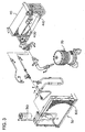
- FIGS. 2 and 3 are explanatory views showing the exterior of the air chiller unit according to the present invention and the general structure of the refrigeration cycle unit.
- An air chiller unit referred to as a whole by reference number 1 is equipped with a casing 10, a compressor 20 for a refrigerant disposed within the casing 10, a condenser 30, an evaporator 40 and a blower device 60 for blowing air.
- the refrigeration cycle unit of the air chiller unit is equipped with a compressor 20 driven by a motor, for compressing the refrigerant and sending out the same toward the condenser 30.
- the condenser 30 is equipped with a heat exchanger 300 for exchanging the gaseous refrigerant to a liquid-phase refrigerant.
- the liquid-phase refrigerant is stored in a receiver drier 310 disposed adjacent to the heat exchanger.
- the liquid-phase refrigerant in the receiver drier 310 is sent via a piping to an evaporator 40 disposed within the air cooling chamber defined by the wall of the casing 10.
- the liquid-phase refrigerant travels through an expansion valve 410 equipped to the evaporator 40 and sent to a heat exchanger 400 of the evaporator.
- the refrigerant is evaporated in the heat exchanger 400 and cools the air passing the heat exchanger 400.
- the expansion valve 410 changes the opening of the valve according to the pressure and temperature of the refrigerant returning toward the compressor 20 from the evaporator 40, to thereby control the flow rate of the refrigerant being sent to the evaporator.
- the blower device 60 has two fans mounted on both ends of a shaft of a motor, and blows air toward the condenser 30 and also blows the cooled air generated in the air cooling chamber toward the service carts placed in the galley of the passenger cabin.
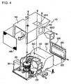
- FIGS. 4 and 5 are explanatory views showing the structure of a casing of the air chiller unit according to the present invention.
- the casing 10 comprises a base plate 100, and on the base plate 100 are mounted devices such as the compressor 20.
- the base plate 100 is formed of a honeycomb panel manufactured by sandwiching a core member having a honeycomb structure between two parallel plate members.
- the honeycomb panel is light weight and has superior flexural rigidity, so the base plate 100 is capable of supporting devices such as the compressor 20 by itself.
- the honeycomb panel Since the honeycomb panel is formed to have air sealed in the honeycomb core, it has high heat insulating property. Therefore, it is suitable for forming the air cooling chamber or the like.
- Apartitionmember 110 formedof ahoneycombpanel is disposed on the base plate 100.
- This partition member 110 is for dividing the air chiller unit into a side having the condenser and a side having the evaporator, and on this partition member 110 is mounted the blower device 60.
- the partitionmember constitutes a portion of the air cooling chamber 130.
- a lid member 120 is mounted on the opening of the partition member 110.
- the lid member 120 connected to a duct device 5 is equipped with a first opening 122 and a second opening 124.
- the first opening 122 is connected to a passage for sending the cool air returning from the galley to the air cooling chamber 130
- the second opening 124 is connected to a passage for sending the freshly cooled air cooled in the air cooling chamber 130 toward the galley.
- a cover member 140 is mounted above the base plate 100, by which the compressor 20 and the blower device 60 are covered.
- the cover member 140 has rectangular openings 144 and 146 on the upper surface and side surface thereof. The openings 144 and 146 are used as exhaust outlets of air having cooled the condenser 30 and the compressor 20.
- a mesh member 148 is attached to the end of the cover member 140, by which the front face of the condenser 30 is covered.
- a round hole 142 for the blower device is provided to the partition member 110. Further, a drain pan 150 for receiving water drops condensed on the evaporator is attached to the bottom of the air cooling chamber.
- the drain pan 150 is equipped with a drain valve 160.
- FIG. 6 is an explanatory view showing the structure of the blower device 60.
- the blower device 60 has a housing 630 constituting a passage for sending out cooled air, and a motor 600 disposed within the housing 630.
- the motor 600 has a drive shaft 602 whose both ends protrude therefrom, and on both ends of the driving shaft are fixed a first fan 610 and a second fan 620.
- the first fan 610 is for sending the air for cooling the side having the condenser 30.
- the second fan 620 is for blowing the air cooled in the air cooling chamber toward the galley.
- the opening of the housing 630 is covered with a cover 640.
- An opening portion 642 of the cover 640 is connected to a second opening 124 of the lidmember 120 for sending the freshly cooled air toward the galley.
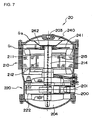
- FIG. 7 is a cross-sectional view showing the structure of the compressor 20, and FIG. 8 is an explanatory view of an oil separator unit.
- the compressor 20 has a cylindrical housing 200, and in the housing 200 is disposed a motor 210 and a rotary compressor 220.
- the motor 210 is equipped with a stator 211 and a rotor 212, and at the center of the rotor 212 is disposed a drive shaft 214.
- the drive shaft 214 of the motor drives a compressor pump 222 to pressurize the refrigerant sent into the compressor through a refrigerant entrance port 201 provided to the housing 200, and sends out the refrigerant through an output port provided at the top of the housing toward the condenser.
- a lubricating oil is supplied to a bottomportion 204 of the housing 200.
- the lubricating oil tends to mix with the compressed refrigerant and flow out through the output port toward the condenser.
- an oil separator unit 240 is provided to separate the lubricating oil from the refrigerant and return the lubricating oil back into the bottom portion 204 of the housing.
- the oil separator unit 240 is structured by having two disks 241 and 242, one disk disposed on top of the other, attached to a top portion of the drive shaft 214 of the motor.
- the two disks rotate together with the drive shaft, creating a two-tiered labyrinth structure by gaps G 1 and G 2 formed between the outer circumferences of the disks and the inner wall of the housing. While passing through this two-tiered labyrinth structure, the lubricating oil is separated from the refrigerant and returned to the bottom of the housing.
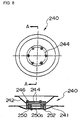
- FIG. 8 is an explanatory view showing the details of the oil separator unit 240.
- Two disks 241 and 242 have at the inner diameter area thereof a fixture member 250, and are assembled integrally via a screw 252.
- the fixture member 250 has its inner diameter area formed into a tapered portion 250a that is tapered toward the upper direction. This tapered portion is used to attach the oil separator unit 240 to the top of the drive shaft 214 using frictional force.
- a fine bore is formed to the center of the drive shaft 214 to allow cooling gas and lubricating oil to pass therethrough. Therefore, it is not possible to adopt a structure to attach the oil separator unit 240 to the drive shaft 214 using a screw or a nut, and thus, the above-described fixing structure is adopted.
- the oil separator unit according to the present invention adopts a structure in which two disks are layered, and the unit is attached to the top of the motor using a fixture member having a tapered portion. Therefore, the present oil separator unit realizes effective oil separation with a short axial direction length.
- a third disk 244 is further disposed on top of the upper disk 242.
- the third disk 244 is attached via a screw 246 on top of the upper disk 242 with a gap formed therebetween.
- the disk 244 is disposed to have a gap formed between the top portion of the drive shaft 214, preventing the refrigerant gas and the lubricating oil discharged from the lubricating oil passage 215 from directly reaching exit 203.
Landscapes
- Engineering & Computer Science (AREA)
- Mechanical Engineering (AREA)
- General Engineering & Computer Science (AREA)
- Health & Medical Sciences (AREA)
- General Health & Medical Sciences (AREA)
- Pulmonology (AREA)
- Aviation & Aerospace Engineering (AREA)
- Physics & Mathematics (AREA)
- Thermal Sciences (AREA)
- Devices That Are Associated With Refrigeration Equipment (AREA)
- Sealing Using Fluids, Sealing Without Contact, And Removal Of Oil (AREA)
- Compressor (AREA)
Description
- The present application is based on and claims priority of
Japanese patent application No. 2003-401778 - The present invention relates to an air chiller unit (air cooling device) equipped within a body of an aircraft, for supplying cooled air to foods or the like.
-
JP 06197490 A - Passenger aircrafts that travel long distances, such as international flights, are equipped with service carts storing meals etc. to be served to passengers, and galleys (kitchen areas) storing the service carts for preparing beverages and carrying out easy food preparation.
- The meals are cooked in advance in service facilities on the ground, placed on trays to be stored in service carts, and brought on board.
- Of the meals placed on the trays, warm dishes are heated by a heater etc., and cold dishes such as salads are maintained at low temperature by cooled air fed into the service carts.
- Patent document 1,
USP NO. 5491979 , discloses an example of a device for cooling service carts. - The air chiller unit is disposed in a space provided on the ceiling or under the floor of the galley in the aircraft. The air chiller unit is equipped with a refrigeration cycle unit, cooling air by an evaporator disposed within a cooling air chamber and supplying the cooled air via a duct to the galley or the like.
- Since the air chiller unit is equipped in an aircraft, the unit is required to be light weight and small sized, and since it is located near the passenger seats, the noise generated by the unit must be reduced.
- The object of the present invention is to provide an air chiller unit that satisfies the above demands.
- The air chiller unit according to the present invention is characterized by the features of claim 1.
- Further, the oil separator unit is equipped with a fixture member having a tapered portion being press fit to a top portion of the drive shaft of the motor.
- As described, the present air chiller unit improves the functions for separating lubricating oil disposed within a compressor for a refrigerant constituting the refrigeration cycle unit of the air chiller unit. Along with the improvement in the performance of the oil separator unit, the size of the housing of the compressor in the axial direction can be reduced, which leads to reducing the size and weight of the air chiller unit equipped in the aircraft.
-
-
FIG. 1 is an explanatory view showing the general structure of the galley; -
FIG. 2 is an explanatory view of an air chiller unit according to the present invention; -
FIG. 3 is an explanatory view of a refrigeration cycle unit of the air chiller unit according to the present invention; -
FIG. 4 is an explanatory view showing the structure of a casing of the air chiller unit according to the present invention; -
FIG. 5 is an explanatory view showing the structure of a casing of the air chiller unit according to the present invention; -
FIG. 6 is an explanatory view of a blower device of the air chiller unit according to the present invention; -
FIG. 7 is an explanatory view of a blower device of the air chiller unit according to the present invention; and -
FIG. 8 is an explanatory view of an oil separator unit. -
FIG. 1 is an explanatory view showing the general structure of a galley equipped with an air chiller unit according to the present invention. - The galley denoted as a whole by
reference number 2 is formed of panel members, and equipped with multiple shelves and storages for storing cooking devices and the like. -
Storage spaces 3 provided on the floor of thegalley 2 are for storing service carts (not shown) storing trays for meals. - Above a
ceiling 4 of thegalley 2 is attached an air chiller unit 1. The air chiller unit 1 is not exposed to the cabin, but disposed within the ceiling of the aircraft. - Arrow F of
FIG. 1 indicates the forward direction of the aircraft body, and a passage for cooled air for cooling the service carts is formed on the back side of thegalley 2 positioned at the forward direction of the aircraft body. - The cool air circulated within the galley is recycled to the air chiller unit 1, where it is cooled to predetermined temperature and then sent out into the galley again.
- A
duct device 5 connected to the air chiller unit 1 is equipped with a passage returning from the interior of the galley and a passage for sending freshly cooled air toward the galley. -
FIGS. 2 and3 are explanatory views showing the exterior of the air chiller unit according to the present invention and the general structure of the refrigeration cycle unit. - An air chiller unit referred to as a whole by reference number 1 is equipped with a
casing 10, acompressor 20 for a refrigerant disposed within thecasing 10, acondenser 30, anevaporator 40 and ablower device 60 for blowing air. - As illustrated in
FIG. 3 , the refrigeration cycle unit of the air chiller unit is equipped with acompressor 20 driven by a motor, for compressing the refrigerant and sending out the same toward thecondenser 30. Thecondenser 30 is equipped with aheat exchanger 300 for exchanging the gaseous refrigerant to a liquid-phase refrigerant. The liquid-phase refrigerant is stored in a receiver drier 310 disposed adjacent to the heat exchanger. The liquid-phase refrigerant in the receiver drier 310 is sent via a piping to anevaporator 40 disposed within the air cooling chamber defined by the wall of thecasing 10. The liquid-phase refrigerant travels through anexpansion valve 410 equipped to theevaporator 40 and sent to aheat exchanger 400 of the evaporator. The refrigerant is evaporated in theheat exchanger 400 and cools the air passing theheat exchanger 400. - The
expansion valve 410 changes the opening of the valve according to the pressure and temperature of the refrigerant returning toward thecompressor 20 from theevaporator 40, to thereby control the flow rate of the refrigerant being sent to the evaporator. - The
blower device 60 has two fans mounted on both ends of a shaft of a motor, and blows air toward thecondenser 30 and also blows the cooled air generated in the air cooling chamber toward the service carts placed in the galley of the passenger cabin. -
FIGS. 4 and5 are explanatory views showing the structure of a casing of the air chiller unit according to the present invention. - The
casing 10 comprises abase plate 100, and on thebase plate 100 are mounted devices such as thecompressor 20. - The
base plate 100 is formed of a honeycomb panel manufactured by sandwiching a core member having a honeycomb structure between two parallel plate members. - The honeycomb panel is light weight and has superior flexural rigidity, so the
base plate 100 is capable of supporting devices such as thecompressor 20 by itself. - Since the honeycomb panel is formed to have air sealed in the honeycomb core, it has high heat insulating property. Therefore, it is suitable for forming the air cooling chamber or the like.
-
Apartitionmember 110 formedof ahoneycombpanel is disposed on thebase plate 100. Thispartition member 110 is for dividing the air chiller unit into a side having the condenser and a side having the evaporator, and on thispartition member 110 is mounted theblower device 60. - The partitionmember constitutes a portion of the
air cooling chamber 130. Alid member 120 is mounted on the opening of thepartition member 110. - The
lid member 120 connected to aduct device 5 is equipped with afirst opening 122 and asecond opening 124. Thefirst opening 122 is connected to a passage for sending the cool air returning from the galley to theair cooling chamber 130, and thesecond opening 124 is connected to a passage for sending the freshly cooled air cooled in theair cooling chamber 130 toward the galley. - A
cover member 140 is mounted above thebase plate 100, by which thecompressor 20 and theblower device 60 are covered. Thecover member 140 hasrectangular openings openings condenser 30 and thecompressor 20. - A
mesh member 148 is attached to the end of thecover member 140, by which the front face of thecondenser 30 is covered. - As illustrated in
FIG. 5 , around hole 142 for the blower device is provided to thepartition member 110. Further, adrain pan 150 for receiving water drops condensed on the evaporator is attached to the bottom of the air cooling chamber. Thedrain pan 150 is equipped with adrain valve 160. -
FIG. 6 is an explanatory view showing the structure of theblower device 60. - The
blower device 60 has ahousing 630 constituting a passage for sending out cooled air, and amotor 600 disposed within thehousing 630. Themotor 600 has adrive shaft 602 whose both ends protrude therefrom, and on both ends of the driving shaft are fixed afirst fan 610 and asecond fan 620. - The
first fan 610 is for sending the air for cooling the side having thecondenser 30. Thesecond fan 620 is for blowing the air cooled in the air cooling chamber toward the galley. The opening of thehousing 630 is covered with acover 640. - An
opening portion 642 of thecover 640 is connected to asecond opening 124 of thelidmember 120 for sending the freshly cooled air toward the galley. -
FIG. 7 is a cross-sectional view showing the structure of thecompressor 20, andFIG. 8 is an explanatory view of an oil separator unit. - The
compressor 20 has acylindrical housing 200, and in thehousing 200 is disposed amotor 210 and arotary compressor 220. - The
motor 210 is equipped with astator 211 and arotor 212, and at the center of therotor 212 is disposed adrive shaft 214. Thedrive shaft 214 of the motor drives acompressor pump 222 to pressurize the refrigerant sent into the compressor through arefrigerant entrance port 201 provided to thehousing 200, and sends out the refrigerant through an output port provided at the top of the housing toward the condenser. - In order to lubricate the rotary portions of the
rotary compressor 220, a lubricating oil is supplied to abottomportion 204 of thehousing 200. The lubricating oil tends to mix with the compressed refrigerant and flow out through the output port toward the condenser. - Therefore, an
oil separator unit 240 is provided to separate the lubricating oil from the refrigerant and return the lubricating oil back into thebottom portion 204 of the housing. - The
oil separator unit 240 according to the present invention is structured by having twodisks drive shaft 214 of the motor. - The two disks rotate together with the drive shaft, creating a two-tiered labyrinth structure by gaps G1 and G2 formed between the outer circumferences of the disks and the inner wall of the housing. While passing through this two-tiered labyrinth structure, the lubricating oil is separated from the refrigerant and returned to the bottom of the housing.
-
FIG. 8 is an explanatory view showing the details of theoil separator unit 240. - Two
disks fixture member 250, and are assembled integrally via ascrew 252. Thefixture member 250 has its inner diameter area formed into a tapered portion 250a that is tapered toward the upper direction. This tapered portion is used to attach theoil separator unit 240 to the top of thedrive shaft 214 using frictional force. - A fine bore is formed to the center of the
drive shaft 214 to allow cooling gas and lubricating oil to pass therethrough. Therefore, it is not possible to adopt a structure to attach theoil separator unit 240 to thedrive shaft 214 using a screw or a nut, and thus, the above-described fixing structure is adopted. - As explained, the oil separator unit according to the present invention adopts a structure in which two disks are layered, and the unit is attached to the top of the motor using a fixture member having a tapered portion. Therefore, the present oil separator unit realizes effective oil separation with a short axial direction length.
- According to the embodiment illustrated in
FIG. 8 , athird disk 244 is further disposed on top of theupper disk 242. - The
third disk 244 is attached via ascrew 246 on top of theupper disk 242 with a gap formed therebetween. - The
disk 244 is disposed to have a gap formed between the top portion of thedrive shaft 214, preventing the refrigerant gas and the lubricating oil discharged from the lubricatingoil passage 215 from directly reachingexit 203.
Claims (2)
- An air chiller unit for an aircraft for supplying cooled air to a storage portion for storing food and the like, the air chiller unit comprising a compressor (20) for a refrigerant constituting a refrigeration cycle unit, the compressor (20) equipped with an oil separator unit (240) comprising:a cylindrical housing (200);a motor (210) disposed in the housing (200): anda rotary compressor (220) driven by the motor (210),characterized by two disks (241,242) attached to a top portion of the drive shaft (214) of the motor (210), one disk (242) disposed on top of the other disk (241),
the oil separator unit (240) having a third disk (244) disposed above the two disks (241,242) and close to a top portion of the drive shaft (14) of the motor (210). - The air chiller unit according to claim 1, wherein the oil separator unit (240) is equipped with a fixture member (250) having a tapered portion (250a) being press fit to a top portion of the drive shaft (214) of the motor (210).
Applications Claiming Priority (2)
| Application Number | Priority Date | Filing Date | Title |
|---|---|---|---|
| JP2003401778 | 2003-12-01 | ||
| JP2003401778A JP4200084B2 (en) | 2003-12-01 | 2003-12-01 | Air chiller device |
Publications (3)
| Publication Number | Publication Date |
|---|---|
| EP1538077A2 EP1538077A2 (en) | 2005-06-08 |
| EP1538077A3 EP1538077A3 (en) | 2006-11-02 |
| EP1538077B1 true EP1538077B1 (en) | 2008-03-26 |
Family
ID=34463929
Family Applications (1)
| Application Number | Title | Priority Date | Filing Date |
|---|---|---|---|
| EP04025702A Expired - Lifetime EP1538077B1 (en) | 2003-12-01 | 2004-10-29 | Air chiller unit |
Country Status (4)
| Country | Link |
|---|---|
| US (1) | US7137273B2 (en) |
| EP (1) | EP1538077B1 (en) |
| JP (1) | JP4200084B2 (en) |
| DE (1) | DE602004012694T2 (en) |
Families Citing this family (8)
| Publication number | Priority date | Publication date | Assignee | Title |
|---|---|---|---|---|
| US8720217B2 (en) * | 2006-07-10 | 2014-05-13 | Mag Aerospace Industries, Inc. | Galley cooling heat sink through water system |
| US8607586B2 (en) * | 2007-02-20 | 2013-12-17 | B/E Aerospace, Inc. | Aircraft galley refrigeration system with multi-circuit heat exchanger |
| CN101625143B (en) * | 2008-07-07 | 2011-11-23 | 松下电器产业株式会社 | multifunctional ventilation fan |
| US9134053B2 (en) | 2011-08-23 | 2015-09-15 | B/E Aerospace, Inc. | Vehicle refrigerator having a liquid line subcooled vapor cycle system |
| WO2013175566A1 (en) * | 2012-05-22 | 2013-11-28 | 株式会社日立製作所 | Refrigerant compressor and refrigeration cycle device |
| CN104500367A (en) * | 2014-12-19 | 2015-04-08 | 苏州市东华试验仪器有限公司 | Compressor set |
| US11286049B2 (en) | 2019-11-12 | 2022-03-29 | B/E Aerospace, Inc. | Standard unit meal box compartment including air chiller |
| US12653922B2 (en) | 2023-09-01 | 2026-06-16 | B/E Aerospace, Inc. | Aircraft lavatory with integrated air ionizer |
Family Cites Families (10)
| Publication number | Priority date | Publication date | Assignee | Title |
|---|---|---|---|---|
| US4361014A (en) * | 1981-03-19 | 1982-11-30 | Sundstrand Corporation | Panel air chiller |
| US4545742A (en) * | 1982-09-30 | 1985-10-08 | Dunham-Bush, Inc. | Vertical axis hermetic helical screw rotary compressor with discharge gas oil mist eliminator and dual transfer tube manifold for supplying liquid refrigerant and refrigerant vapor to the compression area |
| US4715800A (en) * | 1984-10-17 | 1987-12-29 | Nippondenso Co., Ltd. | Rotary compressor with clutch actuated by hydraulic fluid and compressed fluid |
| SE464654B (en) * | 1986-01-31 | 1991-05-27 | Stal Refrigeration Ab | OIL DISPENSER IN A REFRIGERATOR SYSTEM |
| US5222874A (en) * | 1991-01-09 | 1993-06-29 | Sullair Corporation | Lubricant cooled electric drive motor for a compressor |
| KR940002626B1 (en) * | 1991-10-28 | 1994-03-26 | 삼성전자 주식회사 | Compressor |
| JP3301797B2 (en) * | 1992-12-25 | 2002-07-15 | 三洋電機株式会社 | Motor rotor for compressor |
| DE4340316C2 (en) | 1993-11-26 | 1996-03-21 | Daimler Benz Aerospace Airbus | Arrangement for cooling food in an aircraft |
| AU1566695A (en) * | 1994-01-12 | 1995-08-01 | Oceaneering International, Inc. | Enclosure for thermoelectric refrigerator and method |
| US6880351B2 (en) * | 2001-09-05 | 2005-04-19 | Be Intellectual Property, Inc. | Liquid galley refrigeration system for aircraft |
-
2003
- 2003-12-01 JP JP2003401778A patent/JP4200084B2/en not_active Expired - Fee Related
-
2004
- 2004-10-29 DE DE602004012694T patent/DE602004012694T2/en not_active Expired - Lifetime
- 2004-10-29 EP EP04025702A patent/EP1538077B1/en not_active Expired - Lifetime
- 2004-11-24 US US10/995,482 patent/US7137273B2/en not_active Expired - Fee Related
Also Published As
| Publication number | Publication date |
|---|---|
| JP4200084B2 (en) | 2008-12-24 |
| US20050115269A1 (en) | 2005-06-02 |
| EP1538077A3 (en) | 2006-11-02 |
| JP2005161928A (en) | 2005-06-23 |
| EP1538077A2 (en) | 2005-06-08 |
| DE602004012694T2 (en) | 2009-04-09 |
| US7137273B2 (en) | 2006-11-21 |
| DE602004012694D1 (en) | 2008-05-08 |
Similar Documents
| Publication | Publication Date | Title |
|---|---|---|
| US7251952B2 (en) | Air chiller unit | |
| US4361014A (en) | Panel air chiller | |
| US5916253A (en) | Compact trailer refrigeration unit | |
| EP2403728B1 (en) | Aircraft galley cart compartment with point-of-use air chiller | |
| US4434624A (en) | Energy-efficient all-electric ECS for aircraft | |
| US8171749B2 (en) | Ultra small air chiller for aircraft galley | |
| US7137273B2 (en) | Air chiller unit | |
| US7059148B2 (en) | Air chiller unit | |
| EP1527995B1 (en) | Air chiller unit | |
| CN112298575B (en) | Air cooler for confined spaces | |
| CN103998879A (en) | Components installed in an integrated refrigerated container | |
| US7225631B2 (en) | Air chiller unit | |
| US9080809B2 (en) | Cooling device with a fan, a partition and a multiple air flow colliding aperture in the partition for defrosting purposes | |
| EP2072299B1 (en) | Transport refrigeration apparatus | |
| US20020108389A1 (en) | Generator with an axial air gap design for electrically powered trailer refrigeration unit | |
| EP4289737A1 (en) | High efficiency micro-chiller unit | |
| HK1166291B (en) | Aircraft galley cart compartment with point-of-use air chiller |
Legal Events
| Date | Code | Title | Description |
|---|---|---|---|
| PUAI | Public reference made under article 153(3) epc to a published international application that has entered the european phase |
Free format text: ORIGINAL CODE: 0009012 |
|
| AK | Designated contracting states |
Kind code of ref document: A2 Designated state(s): AT BE BG CH CY CZ DE DK EE ES FI FR GB GR HU IE IT LI LU MC NL PL PT RO SE SI SK TR |
|
| AX | Request for extension of the european patent |
Extension state: AL HR LT LV MK |
|
| PUAL | Search report despatched |
Free format text: ORIGINAL CODE: 0009013 |
|
| AK | Designated contracting states |
Kind code of ref document: A3 Designated state(s): AT BE BG CH CY CZ DE DK EE ES FI FR GB GR HU IE IT LI LU MC NL PL PT RO SE SI SK TR |
|
| AX | Request for extension of the european patent |
Extension state: AL HR LT LV MK |
|
| 17P | Request for examination filed |
Effective date: 20070118 |
|
| 17Q | First examination report despatched |
Effective date: 20070221 |
|
| AKX | Designation fees paid |
Designated state(s): DE FR GB |
|
| GRAP | Despatch of communication of intention to grant a patent |
Free format text: ORIGINAL CODE: EPIDOSNIGR1 |
|
| GRAS | Grant fee paid |
Free format text: ORIGINAL CODE: EPIDOSNIGR3 |
|
| GRAA | (expected) grant |
Free format text: ORIGINAL CODE: 0009210 |
|
| AK | Designated contracting states |
Kind code of ref document: B1 Designated state(s): DE FR GB |
|
| REG | Reference to a national code |
Ref country code: GB Ref legal event code: FG4D |
|
| REF | Corresponds to: |
Ref document number: 602004012694 Country of ref document: DE Date of ref document: 20080508 Kind code of ref document: P |
|
| ET | Fr: translation filed | ||
| PLBE | No opposition filed within time limit |
Free format text: ORIGINAL CODE: 0009261 |
|
| STAA | Information on the status of an ep patent application or granted ep patent |
Free format text: STATUS: NO OPPOSITION FILED WITHIN TIME LIMIT |
|
| 26N | No opposition filed |
Effective date: 20081230 |
|
| PGFP | Annual fee paid to national office [announced via postgrant information from national office to epo] |
Ref country code: DE Payment date: 20091028 Year of fee payment: 6 |
|
| PGFP | Annual fee paid to national office [announced via postgrant information from national office to epo] |
Ref country code: FR Payment date: 20091015 Year of fee payment: 6 Ref country code: GB Payment date: 20091006 Year of fee payment: 6 |
|
| GBPC | Gb: european patent ceased through non-payment of renewal fee |
Effective date: 20101029 |
|
| PG25 | Lapsed in a contracting state [announced via postgrant information from national office to epo] |
Ref country code: FR Free format text: LAPSE BECAUSE OF NON-PAYMENT OF DUE FEES Effective date: 20101102 |
|
| REG | Reference to a national code |
Ref country code: FR Ref legal event code: ST Effective date: 20110630 |
|
| PG25 | Lapsed in a contracting state [announced via postgrant information from national office to epo] |
Ref country code: GB Free format text: LAPSE BECAUSE OF NON-PAYMENT OF DUE FEES Effective date: 20101029 |
|
| REG | Reference to a national code |
Ref country code: DE Ref legal event code: R119 Ref document number: 602004012694 Country of ref document: DE Effective date: 20110502 |
|
| PG25 | Lapsed in a contracting state [announced via postgrant information from national office to epo] |
Ref country code: DE Free format text: LAPSE BECAUSE OF NON-PAYMENT OF DUE FEES Effective date: 20110502 |