EP1537917A2 - Miniature fluid dispensing end-effector for geometrically constrained areas - Google Patents
Miniature fluid dispensing end-effector for geometrically constrained areas Download PDFInfo
- Publication number
- EP1537917A2 EP1537917A2 EP04027632A EP04027632A EP1537917A2 EP 1537917 A2 EP1537917 A2 EP 1537917A2 EP 04027632 A EP04027632 A EP 04027632A EP 04027632 A EP04027632 A EP 04027632A EP 1537917 A2 EP1537917 A2 EP 1537917A2
- Authority
- EP
- European Patent Office
- Prior art keywords
- effector
- marking system
- precision marking
- marking
- ink
- Prior art date
- Legal status (The legal status is an assumption and is not a legal conclusion. Google has not performed a legal analysis and makes no representation as to the accuracy of the status listed.)
- Withdrawn
Links
- 239000012636 effector Substances 0.000 title claims abstract description 113
- 239000012530 fluid Substances 0.000 title claims abstract description 55
- 239000000976 ink Substances 0.000 claims description 30
- 238000006073 displacement reaction Methods 0.000 claims description 5
- 239000004593 Epoxy Substances 0.000 claims description 2
- 239000000853 adhesive Substances 0.000 claims description 2
- 230000001070 adhesive effect Effects 0.000 claims description 2
- 239000003973 paint Substances 0.000 claims description 2
- 238000003860 storage Methods 0.000 claims description 2
- 238000000034 method Methods 0.000 description 12
- 239000000523 sample Substances 0.000 description 9
- 230000007246 mechanism Effects 0.000 description 8
- 230000008878 coupling Effects 0.000 description 5
- 238000010168 coupling process Methods 0.000 description 5
- 238000005859 coupling reaction Methods 0.000 description 5
- 238000012423 maintenance Methods 0.000 description 5
- 230000008569 process Effects 0.000 description 5
- 239000003351 stiffener Substances 0.000 description 5
- 230000008901 benefit Effects 0.000 description 4
- 238000005457 optimization Methods 0.000 description 4
- 238000000429 assembly Methods 0.000 description 3
- 239000000654 additive Substances 0.000 description 2
- 230000000996 additive effect Effects 0.000 description 2
- 238000004891 communication Methods 0.000 description 2
- 238000001514 detection method Methods 0.000 description 2
- 238000011161 development Methods 0.000 description 2
- 230000000694 effects Effects 0.000 description 2
- 238000005516 engineering process Methods 0.000 description 2
- 238000009434 installation Methods 0.000 description 2
- 230000033001 locomotion Effects 0.000 description 2
- 239000000463 material Substances 0.000 description 2
- 238000004513 sizing Methods 0.000 description 2
- 238000012546 transfer Methods 0.000 description 2
- 230000009466 transformation Effects 0.000 description 2
- 241001422033 Thestylus Species 0.000 description 1
- 230000004075 alteration Effects 0.000 description 1
- 230000000712 assembly Effects 0.000 description 1
- 230000015572 biosynthetic process Effects 0.000 description 1
- 238000013461 design Methods 0.000 description 1
- 230000009977 dual effect Effects 0.000 description 1
- 230000007613 environmental effect Effects 0.000 description 1
- 230000002349 favourable effect Effects 0.000 description 1
- 238000010304 firing Methods 0.000 description 1
- 230000001788 irregular Effects 0.000 description 1
- 238000003754 machining Methods 0.000 description 1
- 238000004519 manufacturing process Methods 0.000 description 1
- 239000003550 marker Substances 0.000 description 1
- 230000005499 meniscus Effects 0.000 description 1
- 238000003032 molecular docking Methods 0.000 description 1
- 238000004806 packaging method and process Methods 0.000 description 1
- 230000008439 repair process Effects 0.000 description 1
- 239000007787 solid Substances 0.000 description 1
- 239000002904 solvent Substances 0.000 description 1
- 238000006467 substitution reaction Methods 0.000 description 1
- 238000000844 transformation Methods 0.000 description 1
- 210000000707 wrist Anatomy 0.000 description 1
Images






Classifications
-
- B—PERFORMING OPERATIONS; TRANSPORTING
- B41—PRINTING; LINING MACHINES; TYPEWRITERS; STAMPS
- B41J—TYPEWRITERS; SELECTIVE PRINTING MECHANISMS, i.e. MECHANISMS PRINTING OTHERWISE THAN FROM A FORME; CORRECTION OF TYPOGRAPHICAL ERRORS
- B41J3/00—Typewriters or selective printing or marking mechanisms characterised by the purpose for which they are constructed
- B41J3/407—Typewriters or selective printing or marking mechanisms characterised by the purpose for which they are constructed for marking on special material
- B41J3/4073—Printing on three-dimensional objects not being in sheet or web form, e.g. spherical or cubic objects
Definitions
- the present invention relates generally to parts marking systems and methods, and more particularly, a system and method for delivering fluids to surfaces in geometrically constrained spaces.
- Part marking systems address the need to trace components including aircraft, surgical, automotive parts, or other like parts for the duration of their lifetime. These markings can allow parts to be identified and traced to their origin. Additionally these markings can facilitate the assembly of complex structures by providing reference markings or instructions at the assembly point for use in assembling and aligning various parts. To assist in assembly, automated inkjet marking systems often mark locations of hardware and fasteners on part surfaces. This allows the operators to quickly and accurately locate and align sub-assemblies to larger assemblies. Additionally, this avoids the need to construct complicated and expensive jigs to locate sub-assemblies and fasteners.
- FIGURE 1 illustrates the problems associated with marking parts or components 10 wherein the surface normal 12 is at a non-zero angle to the ink stream 14 supplied by the marking head. This results in a displacement of the marking from an intended surface 16 to the actual surface 18.
- Significant alignment errors can be experienced due to an accumulated effect of incorrectly synchronizing system alignments as indicated in the graph provided in FIGURE 2. These additive errors include: (1) the alignment of the calibration monument; (2) end effector (tool centerpoint (TCP)); (3) vision or parts location system (vision system centerpoint); (4) part alignment and orientation in space; and (5) work envelope of the robot. Therefore a need exists for a parts marking system capable of accurately marking parts having surfaces located at a non-normal angles to the end-effector or within confined spaces.
- the present invention provides an automated part marking system that substantially eliminates or reduces disadvantages and problems associated with previously developed systems and methods. More specifically, the present invention provides a system and method to very precisely mark location lines (or dispenses fluids) on surfaces such as bulkheads and frames of an aircraft understructure. The lines aid in visually locating smaller parts (such as brackets and clips) relative to the bulkheads. This allows smaller parts to be fastened in the appropriate position without the need for traditional and expensive custom tooling.
- One embodiment provides an automated part marking system that includes a 6-axis gantry robot, a calibration stand, vision or location system(s), and a series of fluid dispensing (inkjet) end-effectors to accomplish the marking task.
- the end-effector provides the ability to access geometrically confined spaces. This ability was not available in previous end-effectors due to limitations imposed by the size of available inkjet heads for the end-effector.
- Miniaturization/Optimization of the end-effector's dispensing tip improves the system parameters of part population, system accuracy, and system communication potential. Improving this ability greatly improves the functionality of the part marking system. Furthermore, the dispensing tip provides access into very tight spaces. This end-effector addresses the space limitations identified above and provides access into very tight spaces. This is achieved in part by efficiently packaging components of a dispensing system within a small space.
- the stylus/probe of the dispensing tip resembles a dental pick and has an internal orifice with which the fluids are dispensed.
- the radial clearance provided around the orifice improves the part population candidates of the part marking system.
- This end-effector uses a high-speed pulsed valve and orifice within the dispensing tip joined by umbilical tubing to dispense the fluids. Either positive displacement pumps, positive pressure pneumatic reservoir or syringe, or other like delivery systems are used to supply the fluid to the dispensing tip. When compared to traditional systems, this end-effector allows the parts marking system to improve from marking within a Dixie cup, to marking within a thimble.
- the dispensing end-effector stylus being much smaller than previously styluses, allows access to tight spaces giving either a best-case radial clearance between the end-effector hardware and part geometry, or a best-case part marking capability when marking adjacent walls and floors.
- the dispensing end-effector stylus does this while allowing the fluid to remain normal to the intended surface for improved accuracy. Additionally, replaceable items are kept both inexpensive and interchangeable to reduce cost without sacrificing the end-effectors' maintainability or reliability.
- the dispensing end-effector stylus improves the accuracy of the parts marking system. This improved accuracy results in increased locations where markings can be applied. This allows engineering datum and location lines to be more accurately drawn for improved alignment of the brackets. Additionally, this dispensing tip provides increased throwing distances for the dispensed fluids, helping to reduce errors and improve accuracy. This improved accuracy results by minimizing potential elevation errors in the intended marks location if the wall is further away than expected.
- the dispensing end-effector stylus improves the parts marking systems communication potential.
- the end-effector allows the system to mark more of the bracket footprint than was previously possible. Doing so minimizes the need for supporting documentation required to assemble components. Additionally, this dispensing tip allows higher viscosity fluids such as inks, paints, epoxy, or adhesives to be dispensed on the surface.
- this dispensing tip When compared to existing systems, this dispensing tip reduces required daily maintenance, eliminates the need to frequently empty and refill and avoids clogging with better suited fluids that address meniscus formation issues. Fewer clogging issues are present due to a wider selection of fluids available when using positive pressure displacement systems to deliver the fluids.
- a piezoelectric valve is used to control the fluid's drop velocity, wherein the drop velocity depended on the voltage applied to the valve.
- the dispensing end-effector stylus provides an important technical advantage in that its design allows this end-effector to be easily retrofitted on the existing marking system with only minor adjustments.
- the parts marking system provided in this disclosure may be used by any manufacturer, which needs to precisely control the delivery of fluid into a geometrically constrained area.
- the present invention may be applied to aerospace, automotive, as well as other industries that require the ability to precisely deliver fluid into constrained spaces.
- FIGURE 1 illustrates problems associated with existing marking heads as applied to parts having confined geometry spaces
- FIGURE 2 is a graph depicting alignment errors associated with existing parts marking systems
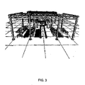
- FIGURE 3 provides a perspective view of one embodiment of a precision marking system in accordance with the present invention.
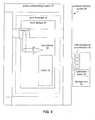
- FIGURE 4 provides a top-down view of one embodiment of a precision marking system in accordance with the present invention
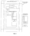
- FIGURE 5 provides a top-down view of a second embodiment of a precision marking system having a robot operably coupled to multiple end effectors;
- FIGURE 6 depicts in further detail and scale the robot of FIGUREs 3, 4 and 5;
- FIGURE 7 depicts one embodiment of an end-effector to dispense fluid in accordance with the present invention.
- FIGURE 8 depicts end-effectors that dispense fluids in geometrically constrained spaces
- FIGURE 9 depicts an end-effector operable to dispense fluids in a geometrically confined space with a surface at a non-normal angle to the surface of the part;
- FIGURE 10 provides a side profile view of a dispensing tip in accordance with the present invention as compared to existing marking or fluid dispensing heads;
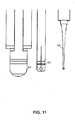
- FIGURE 11 provides a head on view of the dispensing tip of the present invention comparing the marking head and fluid dispensing system of currently available systems;
- FIGURE 12 provides a perspective view of one embodiment of an end effector in accordance with the present invention as compared to existing end-effectors used to dispense marking inks;
- FIGURE 13 depicts the poor resolution associated with current marking systems
- FIGURE 14 illustrates the improved quality of markings available with the end effector provided in accordance with the present invention.
- FIGURES 15 through 19 illustrate the various surfaces on which an end effector in accordance with the present invention may be used to dispense fluids or draw reference lines.
- FIGUREs Preferred embodiments of the present invention are illustrated in the FIGUREs, like numerals being used to refer to like and corresponding parts of the various drawings.
- An Automated Part Marking System helps reduce costs associated with assembling structural components, such as airframes by producing marks accurate enough for operators to locate parts and drill holes (without tooling). This system helps to ensure that assembly tolerances are repeatably maintained.
- the Automated Part Marking System helps eliminate tooling development, rework, and maintenance costs. Additionally, the system functionally operates by modularly locating and marking the larger structural components for the eventual location of smaller detail parts. These smaller detail parts are typically brackets used to secure subsystem components, and their installation occurs at varying times (later) in the assembly process.
- a Part Marking Robotic Work Cell which in one embodiment has an estimated Work Cell Footprint of approximately 80'x 60', with an estimated robot and shuttle footprint of 80'x 20', estimated gantry work envelope of 16' x 9' x 2', and an estimated shuttle table of 14' x 6'.
- the work cell includes a work cell controller, a shuttle transfer mechanism (including two shuttle tables), tooling plates, a six-axis gantry robot, a series of end-effectors, a quick-change end-effector stand, a vision calibration system, and additional ancillary hardware, software, and firmware.
- the work cell controller integrates automated work cell activities.
- the shuttle transfer system acts as a material handling and part docking mechanism for introducing the shuttle tables and parts into the work envelope.
- Tooling plates accurately and repeatably locate parts on the shuttle tables.
- the robot moves the marker heads along preprogrammed paths.
- the end-effectors allow customized line and text marking with ink-jet heads, and force-sensing probes.
- the end-effectors are fully functional and integrated with simultaneous axis robot movements. Additionally, the end-effectors support quick-changes during the part marking process and have failsafe collision detection mechanisms designed in.
- the vision calibration system helps ensure system accuracy by examining the actual end-effector probe alignment, nozzle rotation, and part mark location against theoretical. This comparison allows compensational adjustments for any variability that exists.
- the Automated Part Marking System produces lines and curves on vertical, horizontal, and contoured parts with exceptional precision. These lines will help in visually locating bracket edge positions for assembly.
- the Automated Part Marking System also produces line-based symbols on vertical, horizontal, and contoured part features with exceptional precision. These symbols may define the position of mounting holes, as well as communicate differences in their attachment procedures.
- the Automated Part Marking System may also produce legible text on flat surfaces. The text helps identify the parts to be assembled in near-by locations, and provide other types of helpful work instructions.
- the end-effectors may use quick-change adaptor that prevents the end-effector from uncoupling from the robot in the event of air, vacuum, power, or other utility loss.
- an integrated force-sensing, or multi-clutch mechanism may detect both moment and in-line axial forces to the probes themselves.
- This force sensor may include a Tactile Calibration Head integrated from off-the-shelf technology as known to those skilled in the art.
- FIGURE 3 provides a perspective view of one embodiment of a precision marking system 20 used to place reference markers on object 32 in accordance with the present invention.
- FIGURE 4 provides a top-down view of one embodiment of a precision marking system 20 used to place reference markers on object 32.
- Object 32 may be a structure such as the understructure of an aircraft.
- Object 32 is placed on a work surface 30.
- Aircraft understructures or like objects require the locations for subsequent installation of various brackets, clips, grommets, etc. be precisely marked.
- the brackets and clips hold various equipment and utilities, where alignment of these pieces is critical.
- objects are brought into the work envelop with Dual Platen Shuttle Tables.
- the work surface may use a vacuum system and a combination of pins and plugs to hold the objects rigidly on the table.
- a robot 34 with multiple degrees of freedom and axes of rotation allows interchangeable end-effectors 36 to be positioned precisely relative to work surface 30 and object 32.
- a fluid dispensing end-effector is shown coupled to robot 34.
- other end-effectors may be used to locate and perform other manufacturing processes.
- This marking end-effector facilitates the part marking process.
- One such end-effector is described in further detail within the description of FIGURE 7.
- a gantry type robot is depicted, other robots with the necessary range and freedom of motion may be employed.
- Multiple interchangeable end-effectors 36 are maintained within storage rack 38.
- Calibration stand 39 allows the relative position of robot 34 and end-effector 36 to be calibrated every time it is picked up. Calibration of the marking head requires the system to mark a specific cross-hair pattern on a disposable media. The vision system images this pattern and calculates the actual locations of the markings relative to theoretical.
- FIGURE 5 shows a second embodiment of the precision marking system 20 wherein multiple end-effectors 42 and 36 are coupled to robot 34.
- Location end-effector 42 may employ a vision system to accurately locate objects 32 within the work envelope 40. However, other comparable locations systems may be substituted for vision end-effector 42. Determining the accurate location of objects 32 within the work envelope 40 allows the relative position between object 32 and end-effectors 36 to be determined. After determining the relative location, marking end-effector 36 accurately applies ink or fluids to object 32.
- One vision system includes a camera, lens and light ring, and laser line generator permanently mounted to the three-axis wrist 51 of robot 34 and is used to locate object 32 and its features.
- the vision system moves to a theoretical target location and images the actual location, then determines the X and Y coordinates of specific points or features on the object.
- An actual location is determined with a combination of imaged features.
- the elevation of the part is determined with a laser line projected at an angle onto the part.
- the camera picks up the location of this line and determines the height of the part by comparing where the line is in the image recorded by the camera and where the line is supposed to be based on the angle between the camera and the laser line generator. From these three inputs, a 6-degree part transformation is created by the control system coupled to the precision marking system 20.
- the vision system can find edges of upstanding stiffeners, with the laser line projected across a stiffener and imaged by the camera. Analyzing the image reveals the left or right most end of the line, which represents the location of the desired edge of the stiffener. Images gathered may be used to create local transformations when required for extra precision.
- FIGURE 6 provides an enlarged view of Robot 34, which is coupled to gantry system 53 of FIGUREs 3, 4 and 5.
- robot 34 comprises multiple arms segments 48 and 49 coupled together by joints 51 in order to allow robot 34 to reposition the interchangeable end-effector 36 within work envelope 40.
- Segments 48 and 49 are linked by joints 51, 55 and 57 to provide robot 34 the ability to position end-effector 36 at any point in the X, Y, and Z direction within 3-D work envelope 40. Additionally the ability of joints 51, 55 and 57 to rotate allows end-effector 36 to not only be positioned but rotated at any required angle relative to object 32.
- FIGURE 7 provides a more detailed view of fluid dispensing end-effector 36.
- End-effector 36 is an interchangeable end-effector having a quick-change adaptor 44, allowing the end-effector 36 to be interchangeably coupled to robot 34 via receiving plate 52 as depicted in FIGURE 6.
- the quick-change adaptor prevents the end-effector from uncoupling from the robot in the event of air, vacuum, power, or other utility loss.
- an integrated force-sensing, or multi-clutch mechanism may detect both moment and in-line axial forces to the probes themselves.
- This force sensor may include a Tactile Calibration Head integrated from off-the-shelf technology as known to those skilled in the art.
- Faceplate 46 serves to secure and orient end-effector 36 to the receiving plate 52 of robot 34.
- alignment features 50 such as holes and/or guide pins, align the end-effector to the receiving plate 52 of the robot.
- Umbilicals couple to end-effector 36 to provide power, hydraulics, fluids or other supplies to end-effector 36 via robot 34.
- Mounting plate 54 secures housing 56 that contains various components in the end-effector, to faceplate 46. These components include pump 57, mounting bracket 58, syringe or fluid reservoir 60, filter 62, and internal tubing 63.
- Alignments points 64 located at the bottom of housing 56 allowed the robot 34 to calibrate and precisely determine the position of the end-effector prior to each usage of the end-effector.
- Probe 66 receives filtered fluids drawn from reservoir 60 by pump 57 through internal tubing 63.
- High-speed pulse valve 67 allows this fluid to be precisely metered to dispensing tip's 68 stylus that ends in orifice 70.
- the low profile nature of dispensing tip 68 allows this end-effector to precisely mark parts or dispense fluids to geometrically confined spaces of objects that could not previously be marked with existing end-effectors.
- Orifice 70 angles away from dispensing tip 68 in FIGURE 7 to facilitate dispensing fluids on a wall extending upwards from the surface (or floor) of object 32. In other embodiments, orifice 70 may be angled to facilitate the disposition of fluids on the floor rather than the wall.
- An integrated collision detection system prevents collisions between the object and the end-effector. Additionally, the dispensing tip is made from material with low coefficient of friction values, part marring in the event of a collision may be prevented. The weak-link failure location designed-in may cause the dispensing tip to snap in the event of catastrophic system failure.
- FIGURE 8 depicts two embodiments wherein dispensing tip 68A has an orifice angled to deposit or dispense fluids on wall 72 of object 32 or on the floor 74 of object 32 with a dispending tip 68B.
- FIGURE 9 illustrates that robot 34 may locate or position end-effector 36 at an angle such that dispensing probe tip 68 are better suited to dispense fluids on wall 72 when wall 72 is not located at an angle normal to the surface of object 32.
- FIGUREs 10, 11, and 12 compare the profile of dispensing tip 68 of the present invention to those of currently available fluid dispensing or ink jet systems.
- a side profile of dispensing tip 68 is compared to currently available ink jet marking head 80 and a prototype fluid dispensing system 82.
- FIGURE 11 provides a front view of dispensing tip 68 as compared to ink jet marking head 80 and fluid dispensing system 82.
- FIGURE 12 combines these views to provide prospective views of end-effector utilizing these different fluid-dispensing systems.
- end-effector 36 on the right is compared to an ink jet marking head 86 having the ink jet applicator 80 of FIGUREs 10 and 11, while end-effector 88 has fluid dispensing head 82 of FIGUREs 10 and 11.
- the present invention precision marking system and end-effector provided by reference or supporting documentation on an object allows marking lines to enable users to more quickly and accurately position subassemblies to the object. Furthermore, the present invention may be used to mark attached components to the object for further assembly or use. In addition, marking the object, subassemblies such as flanges stiffeners may be marked for additional subassemblies.
- FIGUREs 13 and 14 depict the improved accuracy associated with dispensing tip 68 over prior marking systems. An example of reference lines using commercially available marking systems is depicted in FIGURE 13. Lines do not provide the required accuracy to assemble components that demand. In comparison, more accurate reference markers exemplified by the markings of FIGURE 14 facilitate meeting these tight requirements.
- the reduced profile of the dispensing tip help to reduce or eliminate alignment errors induced by the gap, between the fluid dispensing system and object to be marked. These inaccuracies originally described in FIGURE 1 and FIGURE 2, are reduced by insuring alignment to surface normal is maintained in all geometrically constrained areas.
- Part marking system can reduce costs associated with assembling structural components, such as airframes by producing marks accurate enough for operators to locate parts and further machine the part (without expensive custom tooling). This invention helps to ensure that assembly tolerances are repeatably maintained. Custom tooling development, rework, and maintenance costs are greatly reduced by this marking system.
- the automated part marking system can produce lines and curves on vertical, horizontal, angle, and contoured parts with exceptional precision. These lines visually locate assembly positions. Also, line-based symbols on vertical, horizontal, angled, and contoured part features with exceptional precision. These symbols may define the position of mounting holes, as well as communicate differences in their attachment procedures. Legible text written on surfaces helps identify the parts to be assembled in near-by locations, and provide other types of helpful work instructions.
- end-effector 36 can be repositioned by the system controller to follow part contour normals.
- performance parameters (1) availability of end-effector to work cell, (2) accuracy of intended line marking, (3) producability of line marking in tight spaces, (4) robustness of operation including reliability, quality, and repeatability of part line mark; and interoperability consistency between copies of end-effectors, and (5) maintainability of operation including interchangeability/ replacability of spare parts.
- Replaceable/consumable items may be modular in nature to hasten repairs and improve maintainability.
- the geometrically constrained areas are as follows: (1) Work volume restricted to 1.0 X 1.0 X 4.0 inch cube in axis X, Y, Z respectively; Work volume restricted @ +/- 100 degrees about tool centerpoint X; Work volume restricted @ +/- 100 degrees about tool centerpoint y; Work volume restricted @ +/- 360 degrees about tool centerpoint Z; Mark location all areas of interior walls. Representative Part Markings are Described in TABLE 2:
- the text capability of the end-effector allows the end-effector to mark text with the following constraints in geometrically constrained areas.
- the end-effector produces legible text of: various fonts such as Arial (Narrow font desired due to space constraints); Special Characters - Arrow that is proportionally sized and in-line with characters being produced; Font size(s) - 6-12 pt; Font style(s) - Regular (Italics, Bold, & Bold Italics desired if sizing constraints permits); Font color(s) - One (black), (Red desired if sizing and cost constraints permits); Font length(s) - 18 proportional characters within 2.5 inches.
- fonts such as Arial (Narrow font desired due to space constraints); Special Characters - Arrow that is proportionally sized and in-line with characters being produced; Font size(s) - 6-12 pt; Font style(s) - Regular (Italics, Bold, & Bold Italics desired if sizing constraints permits); Font color(s) - One (black), (Red desired if sizing and cost constraints permits); Font length(s) -
- the Ink(s) selected for use in the end-effectors may be selected with ranked attention to: (1) optimization of mark accuracy, (2) optimization of mark quality, (3) ability to repeatably propel itself from ink jet head a specified distances ( ⁇ 0.100), (4) optimization of dry time, (5) maintainability characteristics of ink within Marking End-effectors, and (6) compliance with safety regulations.
- These inks selected for use in marking end-effectors may produce accurate and repeatable marks on paint-primed surfaces.
- the inks selected for use in marking end-effectors selected for use may cure to touch (not smudge) within about 30 seconds after mark is made. Additionally, these ink(s) may not require extensive maintenance provisions (routinely clog in any part of end-effector assembly). Cleansing procedures defined for routine maintenance and optimal performance of ink jet ports may involve solvents compliant with environmental requirements.
- the present invention provides an end-effector to precisely mark location lines (or dispense fluids) on surfaces as part of an automated part marking system.
- the automated part marking system that includes a multi-axis gantry robot, a calibration stand, vision or location system(s), and a series of fluid dispensing (inkjet) end-effectors to accomplish the marking task.
- the end-effector use a pick shaped stylus coupled to a fluid supply and metered by a high-speed pulsed valve to precisely deliver fluids provides within geometrically confined spaces.
- An integrated calibration monument allows the multi-axis gantry robot to precisely determine the position of the tool centerpoint in space. This alignment is routinely performed. For example, this alignment may be performed as part of every marking process. This alignment may be applied to the vision or parts location system as well. By knowing the relative distance between the tool centerpoint and the parts location in space, the integrated system can accurately determine the parts position and alignment in space. This combined knowledge allows the end effector to accurately place the desired graphics on the part.
- FIGURES 15 through 19 illustrate the various surfaces on which an end effector in accordance with the present invention may be used to dispense fluids or draw reference lines.
- the term “substantially” or “approximately”, as may be used herein, provides an industry-accepted tolerance to its corresponding term. Such an industry-accepted tolerance ranges from less than one percent to twenty percent and corresponds to, but is not limited to, component values, integrated circuit process variations, temperature variations, rise and fall times, and/or thermal noise.
- the term “operably coupled”, as may be used herein, includes direct coupling and indirect coupling via another component, element, circuit, or module where, for indirect coupling, the intervening component, element, circuit, or module does not modify the information of a signal but may adjust its current level, voltage level, and/or power level.
- inferred coupling includes direct and indirect coupling between two elements in the same manner as “operably coupled”.
- the term "compares favorably”, as may be used herein indicates that a comparison between two or more elements, items, signals, etc., provides a desired relationship. For example, when the desired relationship is that signal 1 has a greater magnitude than signal 2, a favorable comparison may be achieved when the magnitude of signal 1 is greater than that of signal 2 or when the magnitude of signal 2 is less than that of signal 1.
Landscapes
- Engineering & Computer Science (AREA)
- Manufacturing & Machinery (AREA)
- Coating Apparatus (AREA)
- Application Of Or Painting With Fluid Materials (AREA)
Abstract
Description
- This application claims the benefit of priority to U.S. Provisional Patent Application No. 60/526,034 entitled "Miniature Fluid Dispensing End-Effector for Geometrically Constrained Areas", filed on December 1, 2003, and is incorporated herein by reference in its entirety.
- The present invention relates generally to parts marking systems and methods, and more particularly, a system and method for delivering fluids to surfaces in geometrically constrained spaces.
- Part marking systems address the need to trace components including aircraft, surgical, automotive parts, or other like parts for the duration of their lifetime. These markings can allow parts to be identified and traced to their origin. Additionally these markings can facilitate the assembly of complex structures by providing reference markings or instructions at the assembly point for use in assembling and aligning various parts. To assist in assembly, automated inkjet marking systems often mark locations of hardware and fasteners on part surfaces. This allows the operators to quickly and accurately locate and align sub-assemblies to larger assemblies. Additionally, this avoids the need to construct complicated and expensive jigs to locate sub-assemblies and fasteners.
- Current inkjet marking systems provide only horizontal or vertical firing. This adequately addresses the marking of horizontal and vertical surfaces. However, this fails to address the need to appropriately mark components with geometrically confined spaces or surfaces at non-normal angles to the inkjet marking system. Currently, known parts marking systems lack the ability to handle irregular shaped and cylindrical parts having various surface projections such as flanges or stiffeners that are located at non-normal angles to the parts surface. Previously these complex structures were marked by hand or required expensive and unique tooling in order to properly mark attachment locations for the machining of the part.
- Additionally, because current inkjet effecters fire only in the horizontal or in the vertical direction, alignment errors may be induced on non-planar surfaces by the angle between the ink stream and the surface normal of the part to be marked. Another problem arises from constraints associated with part geometry depending on the depth and the size of the area to be marked as existing marking heads cannot reach into confined spaces.
- FIGURE 1 illustrates the problems associated with marking parts or
components 10
wherein the surface normal 12 is at a non-zero angle to the ink stream 14 supplied by the marking head. This results in a displacement of the marking from an intendedsurface 16 to theactual surface 18. Significant alignment errors can be experienced due to an accumulated effect of incorrectly synchronizing system alignments as indicated in the graph provided in FIGURE 2. These additive errors include: (1) the alignment of the calibration monument; (2) end effector (tool centerpoint (TCP)); (3) vision or parts location system (vision system centerpoint); (4) part alignment and orientation in space; and (5) work envelope of the robot. Therefore a need exists for a parts marking system capable of accurately marking parts having surfaces located at a non-normal angles to the end-effector or within confined spaces. - The present invention provides an automated part marking system that substantially eliminates or reduces disadvantages and problems associated with previously developed systems and methods. More specifically, the present invention provides a system and method to very precisely mark location lines (or dispenses fluids) on surfaces such as bulkheads and frames of an aircraft understructure. The lines aid in visually locating smaller parts (such as brackets and clips) relative to the bulkheads. This allows smaller parts to be fastened in the appropriate position without the need for traditional and expensive custom tooling.
- One embodiment provides an automated part marking system that includes a 6-axis gantry robot, a calibration stand, vision or location system(s), and a series of fluid dispensing (inkjet) end-effectors to accomplish the marking task. The end-effector provides the ability to access geometrically confined spaces. This ability was not available in previous end-effectors due to limitations imposed by the size of available inkjet heads for the end-effector.
- Miniaturization/Optimization of the end-effector's dispensing tip improves the system parameters of part population, system accuracy, and system communication potential. Improving this ability greatly improves the functionality of the part marking system. Furthermore, the dispensing tip provides access into very tight spaces. This end-effector addresses the space limitations identified above and provides access into very tight spaces. This is achieved in part by efficiently packaging components of a dispensing system within a small space.
- The stylus/probe of the dispensing tip resembles a dental pick and has an internal orifice with which the fluids are dispensed. The radial clearance provided around the orifice improves the part population candidates of the part marking system.
- This end-effector uses a high-speed pulsed valve and orifice within the dispensing tip joined by umbilical tubing to dispense the fluids. Either positive displacement pumps, positive pressure pneumatic reservoir or syringe, or other like delivery systems are used to supply the fluid to the dispensing tip. When compared to traditional systems, this end-effector allows the parts marking system to improve from marking within a Dixie cup, to marking within a thimble.
- The dispensing end-effector stylus being much smaller than previously styluses, allows access to tight spaces giving either a best-case radial clearance between the end-effector hardware and part geometry, or a best-case part marking capability when marking adjacent walls and floors. The dispensing end-effector stylus does this while allowing the fluid to remain normal to the intended surface for improved accuracy. Additionally, replaceable items are kept both inexpensive and interchangeable to reduce cost without sacrificing the end-effectors' maintainability or reliability.
- The dispensing end-effector stylus improves the accuracy of the parts marking system. This improved accuracy results in increased locations where markings can be applied. This allows engineering datum and location lines to be more accurately drawn for improved alignment of the brackets. Additionally, this dispensing tip provides increased throwing distances for the dispensed fluids, helping to reduce errors and improve accuracy. This improved accuracy results by minimizing potential elevation errors in the intended marks location if the wall is further away than expected.
- The dispensing end-effector stylus improves the parts marking systems communication potential. The end-effector allows the system to mark more of the bracket footprint than was previously possible. Doing so minimizes the need for supporting documentation required to assemble components. Additionally, this dispensing tip allows higher viscosity fluids such as inks, paints, epoxy, or adhesives to be dispensed on the surface.
- When compared to existing systems, this dispensing tip reduces required daily maintenance, eliminates the need to frequently empty and refill and avoids clogging with better suited fluids that address meniscus formation issues. Fewer clogging issues are present due to a wider selection of fluids available when using positive pressure displacement systems to deliver the fluids. In previous solutions a piezoelectric valve is used to control the fluid's drop velocity, wherein the drop velocity depended on the voltage applied to the valve.
- The dispensing end-effector stylus provides an important technical advantage in that its design allows this end-effector to be easily retrofitted on the existing marking system with only minor adjustments.
- The parts marking system provided in this disclosure may be used by any manufacturer, which needs to precisely control the delivery of fluid into a geometrically constrained area. Thus, the present invention may be applied to aerospace, automotive, as well as other industries that require the ability to precisely deliver fluid into constrained spaces.
- For a more complete understanding of the present invention and the advantages thereof, reference is now made to the following description taken in conjunction with the accompanying drawings in which like reference numerals indicate like features and wherein:
- FIGURE 1 illustrates problems associated with existing marking heads as applied to parts having confined geometry spaces;
- FIGURE 2 is a graph depicting alignment errors associated with existing parts marking systems;
- FIGURE 3 provides a perspective view of one embodiment of a precision marking system in accordance with the present invention;
- FIGURE 4 provides a top-down view of one embodiment of a precision marking system in accordance with the present invention;
- FIGURE 5 provides a top-down view of a second embodiment of a precision marking system having a robot operably coupled to multiple end effectors;
- FIGURE 6 depicts in further detail and scale the robot of FIGUREs 3, 4 and 5;
- FIGURE 7 depicts one embodiment of an end-effector to dispense fluid in accordance with the present invention;
- FIGURE 8 depicts end-effectors that dispense fluids in geometrically constrained spaces;
- FIGURE 9 depicts an end-effector operable to dispense fluids in a geometrically confined space with a surface at a non-normal angle to the surface of the part;
- FIGURE 10 provides a side profile view of a dispensing tip in accordance with the present invention as compared to existing marking or fluid dispensing heads;
- FIGURE 11 provides a head on view of the dispensing tip of the present invention comparing the marking head and fluid dispensing system of currently available systems;
- FIGURE 12 provides a perspective view of one embodiment of an end effector in accordance with the present invention as compared to existing end-effectors used to dispense marking inks;
- FIGURE 13 depicts the poor resolution associated with current marking systems;
- FIGURE 14 illustrates the improved quality of markings available with the end effector provided in accordance with the present invention; and
- FIGURES 15 through 19 illustrate the various surfaces on which an end effector in accordance with the present invention may be used to dispense fluids or draw reference lines.
- Preferred embodiments of the present invention are illustrated in the FIGUREs, like numerals being used to refer to like and corresponding parts of the various drawings.
- An Automated Part Marking System helps reduce costs associated with assembling structural components, such as airframes by producing marks accurate enough for operators to locate parts and drill holes (without tooling). This system helps to ensure that assembly tolerances are repeatably maintained. The Automated Part Marking System helps eliminate tooling development, rework, and maintenance costs. Additionally, the system functionally operates by modularly locating and marking the larger structural components for the eventual location of smaller detail parts. These smaller detail parts are typically brackets used to secure subsystem components, and their installation occurs at varying times (later) in the assembly process.
- A Part Marking Robotic Work Cell is employed which in one embodiment has an estimated Work Cell Footprint of approximately 80'x 60', with an estimated robot and shuttle footprint of 80'x 20', estimated gantry work envelope of 16' x 9' x 2', and an estimated shuttle table of 14' x 6'. The work cell includes a work cell controller, a shuttle transfer mechanism (including two shuttle tables), tooling plates, a six-axis gantry robot, a series of end-effectors, a quick-change end-effector stand, a vision calibration system, and additional ancillary hardware, software, and firmware. The work cell controller integrates automated work cell activities.
- The shuttle transfer system acts as a material handling and part docking mechanism for introducing the shuttle tables and parts into the work envelope. Tooling plates accurately and repeatably locate parts on the shuttle tables. The robot moves the marker heads along preprogrammed paths.
- The end-effectors allow customized line and text marking with ink-jet heads, and force-sensing probes. The end-effectors are fully functional and integrated with simultaneous axis robot movements. Additionally, the end-effectors support quick-changes during the part marking process and have failsafe collision detection mechanisms designed in.
- The vision calibration system helps ensure system accuracy by examining the actual end-effector probe alignment, nozzle rotation, and part mark location against theoretical. This comparison allows compensational adjustments for any variability that exists.
- The Automated Part Marking System produces lines and curves on vertical, horizontal, and contoured parts with exceptional precision. These lines will help in visually locating bracket edge positions for assembly. The Automated Part Marking System also produces line-based symbols on vertical, horizontal, and contoured part features with exceptional precision. These symbols may define the position of mounting holes, as well as communicate differences in their attachment procedures. The Automated Part Marking System may also produce legible text on flat surfaces. The text helps identify the parts to be assembled in near-by locations, and provide other types of helpful work instructions.
- The end-effectors may use quick-change adaptor that prevents the end-effector from uncoupling from the robot in the event of air, vacuum, power, or other utility loss. Additionally, an integrated force-sensing, or multi-clutch mechanism may detect both moment and in-line axial forces to the probes themselves. This force sensor may include a Tactile Calibration Head integrated from off-the-shelf technology as known to those skilled in the art.
- FIGURE 3 provides a perspective view of one embodiment of a
precision marking system 20 used to place reference markers onobject 32 in accordance with the present invention. FIGURE 4 provides a top-down view of one embodiment of aprecision marking system 20 used to place reference markers onobject 32.Object 32 may be a structure such as the understructure of an aircraft.Object 32 is placed on awork surface 30. Aircraft understructures or like objects require the locations for subsequent installation of various brackets, clips, grommets, etc. be precisely marked. The brackets and clips hold various equipment and utilities, where alignment of these pieces is critical. In one embodiment, objects are brought into the work envelop with Dual Platen Shuttle Tables. The work surface may use a vacuum system and a combination of pins and plugs to hold the objects rigidly on the table. - A
robot 34 with multiple degrees of freedom and axes of rotation allows interchangeable end-effectors 36 to be positioned precisely relative towork surface 30 andobject 32. As depicted, a fluid dispensing end-effector is shown coupled torobot 34. However, other end-effectors may be used to locate and perform other manufacturing processes. This marking end-effector facilitates the part marking process. One such end-effector is described in further detail within the description of FIGURE 7. Although a gantry type robot is depicted, other robots with the necessary range and freedom of motion may be employed. Multiple interchangeable end-effectors 36 are maintained withinstorage rack 38. Calibration stand 39 allows the relative position ofrobot 34 and end-effector 36 to be calibrated every time it is picked up. Calibration of the marking head requires the system to mark a specific cross-hair pattern on a disposable media. The vision system images this pattern and calculates the actual locations of the markings relative to theoretical. - FIGURE 5 shows a second embodiment of the
precision marking system 20 wherein multiple end-effectors robot 34. Location end-effector 42 may employ a vision system to accurately locateobjects 32 within thework envelope 40. However, other comparable locations systems may be substituted for vision end-effector 42. Determining the accurate location ofobjects 32 within thework envelope 40 allows the relative position betweenobject 32 and end-effectors 36 to be determined. After determining the relative location, marking end-effector 36 accurately applies ink or fluids to object 32. - One vision system includes a camera, lens and light ring, and laser line generator permanently mounted to the three-
axis wrist 51 ofrobot 34 and is used to locateobject 32 and its features. To locate the object, the vision system moves to a theoretical target location and images the actual location, then determines the X and Y coordinates of specific points or features on the object. An actual location is determined with a combination of imaged features. The elevation of the part is determined with a laser line projected at an angle onto the part. The camera picks up the location of this line and determines the height of the part by comparing where the line is in the image recorded by the camera and where the line is supposed to be based on the angle between the camera and the laser line generator. From these three inputs, a 6-degree part transformation is created by the control system coupled to theprecision marking system 20. - In addition to locating targets and surfaces, the vision system can find edges of upstanding stiffeners, with the laser line projected across a stiffener and imaged by the camera. Analyzing the image reveals the left or right most end of the line, which represents the location of the desired edge of the stiffener. Images gathered may be used to create local transformations when required for extra precision.
- FIGURE 6 provides an enlarged view of
Robot 34, which is coupled togantry system 53 of FIGUREs 3, 4 and 5. Hererobot 34 comprisesmultiple arms segments 48 and 49 coupled together byjoints 51 in order to allowrobot 34 to reposition the interchangeable end-effector 36 withinwork envelope 40.Segments 48 and 49 are linked byjoints robot 34 the ability to position end-effector 36 at any point in the X, Y, and Z direction within 3-D work envelope 40. Additionally the ability ofjoints effector 36 to not only be positioned but rotated at any required angle relative to object 32. - FIGURE 7 provides a more detailed view of fluid dispensing end-
effector 36. End-effector 36 is an interchangeable end-effector having a quick-change adaptor 44, allowing the end-effector 36 to be interchangeably coupled torobot 34 via receivingplate 52 as depicted in FIGURE 6. The quick-change adaptor prevents the end-effector from uncoupling from the robot in the event of air, vacuum, power, or other utility loss. Additionally, an integrated force-sensing, or multi-clutch mechanism may detect both moment and in-line axial forces to the probes themselves. This force sensor may include a Tactile Calibration Head integrated from off-the-shelf technology as known to those skilled in the art. -
Faceplate 46 serves to secure and orient end-effector 36 to the receivingplate 52 ofrobot 34. To align end-effector 36, alignment features 50, such as holes and/or guide pins, align the end-effector to the receivingplate 52 of the robot. Umbilicals couple to end-effector 36 to provide power, hydraulics, fluids or other supplies to end-effector 36 viarobot 34. Mountingplate 54 secures housing 56 that contains various components in the end-effector, tofaceplate 46. These components includepump 57, mountingbracket 58, syringe orfluid reservoir 60,filter 62, andinternal tubing 63. Alignments points 64 located at the bottom of housing 56 allowed therobot 34 to calibrate and precisely determine the position of the end-effector prior to each usage of the end-effector.Probe 66 receives filtered fluids drawn fromreservoir 60 bypump 57 throughinternal tubing 63. High-speed pulse valve 67 allows this fluid to be precisely metered to dispensing tip's 68 stylus that ends inorifice 70. The low profile nature of dispensingtip 68 allows this end-effector to precisely mark parts or dispense fluids to geometrically confined spaces of objects that could not previously be marked with existing end-effectors.Orifice 70 angles away from dispensingtip 68 in FIGURE 7 to facilitate dispensing fluids on a wall extending upwards from the surface (or floor) ofobject 32. In other embodiments,orifice 70 may be angled to facilitate the disposition of fluids on the floor rather than the wall. - An integrated collision detection system (such as force sensing, and/or multi-clutch mechanisms) prevents collisions between the object and the end-effector. Additionally, the dispensing tip is made from material with low coefficient of friction values, part marring in the event of a collision may be prevented. The weak-link failure location designed-in may cause the dispensing tip to snap in the event of catastrophic system failure.
- FIGURE 8 depicts two embodiments wherein dispensing tip 68A has an orifice angled to deposit or dispense fluids on
wall 72 ofobject 32 or on thefloor 74 ofobject 32 with a dispending tip 68B. FIGURE 9 illustrates thatrobot 34 may locate or position end-effector 36 at an angle such that dispensingprobe tip 68 are better suited to dispense fluids onwall 72 whenwall 72 is not located at an angle normal to the surface ofobject 32. - FIGUREs 10, 11, and 12 compare the profile of dispensing
tip 68 of the present invention to those of currently available fluid dispensing or ink jet systems. In FIGURE 10, a side profile of dispensingtip 68 is compared to currently available inkjet marking head 80 and a prototypefluid dispensing system 82. FIGURE 11 provides a front view of dispensingtip 68 as compared to inkjet marking head 80 andfluid dispensing system 82. FIGURE 12 combines these views to provide prospective views of end-effector utilizing these different fluid-dispensing systems. Here, end-effector 36 on the right is compared to an inkjet marking head 86 having theink jet applicator 80 of FIGUREs 10 and 11, while end-effector 88 hasfluid dispensing head 82 of FIGUREs 10 and 11. These FIGUREs clearly evidence one advantage provided by the present invention wherein the dispensing tip increases access to geometrically confined areas. - The present invention precision marking system and end-effector provided by reference or supporting documentation on an object allows marking lines to enable users to more quickly and accurately position subassemblies to the object. Furthermore, the present invention may be used to mark attached components to the object for further assembly or use. In addition, marking the object, subassemblies such as flanges stiffeners may be marked for additional subassemblies. FIGUREs 13 and 14 depict the improved accuracy associated with dispensing
tip 68 over prior marking systems. An example of reference lines using commercially available marking systems is depicted in FIGURE 13. Lines do not provide the required accuracy to assemble components that demand. In comparison, more accurate reference markers exemplified by the markings of FIGURE 14 facilitate meeting these tight requirements. The reduced profile of the dispensing tip help to reduce or eliminate alignment errors induced by the gap, between the fluid dispensing system and object to be marked. These inaccuracies originally described in FIGURE 1 and FIGURE 2, are reduced by insuring alignment to surface normal is maintained in all geometrically constrained areas. - Part marking system can reduce costs associated with assembling structural components, such as airframes by producing marks accurate enough for operators to locate parts and further machine the part (without expensive custom tooling). This invention helps to ensure that assembly tolerances are repeatably maintained. Custom tooling development, rework, and maintenance costs are greatly reduced by this marking system.
- The automated part marking system can produce lines and curves on vertical, horizontal, angle, and contoured parts with exceptional precision. These lines visually locate assembly positions. Also, line-based symbols on vertical, horizontal, angled, and contoured part features with exceptional precision. These symbols may define the position of mounting holes, as well as communicate differences in their attachment procedures. Legible text written on surfaces helps identify the parts to be assembled in near-by locations, and provide other types of helpful work instructions.
- In one embodiment, end-
effector 36 can be repositioned by the system controller to follow part contour normals. There, particular attention is paid to the following performance parameters: (1) availability of end-effector to work cell, (2) accuracy of intended line marking, (3) producability of line marking in tight spaces, (4) robustness of operation including reliability, quality, and repeatability of part line mark; and interoperability consistency between copies of end-effectors, and (5) maintainability of operation including interchangeability/ replacability of spare parts. This allows the end-effector to be manufactured maximize availability. Replaceable/consumable items (Pumps, Solenoids, Probes, Stylus, Jet Heads, Etc.) may be modular in nature to hasten repairs and improve maintainability. - The optimized line-marking accuracy, and repeatable with a reliable quick-change mechanism that maximizes repeatability of end-effector positional accuracy when coupled to the robot. A repeatable and reliable probe locating mechanism maximizes repeatability of the ink jet egress location(s) throughout end-effectors. Programmable lines may be produced by the end-effector as described by TABLE 1.
Line type(s) straight & non-closing curves Width(s) Range 0.020 - 0.060 inches (Optimal values TBD via trials) Length(s) Range 0.5 - 7.0 inches typical Formats Solid and dashed Color various - The geometrically constrained areas. In one embodiment, these restrictions are as follows: (1) Work volume restricted to 1.0 X 1.0 X 4.0 inch cube in axis X, Y, Z respectively; Work volume restricted @ +/- 100 degrees about tool centerpoint X; Work volume restricted @ +/- 100 degrees about tool centerpoint y; Work volume restricted @ +/- 360 degrees about tool centerpoint Z; Mark location all areas of interior walls. Representative Part Markings are Described in TABLE 2:

- The text capability of the end-effector allows the end-effector to mark text with the following constraints in geometrically constrained areas. (1) Work volume restricted to 2.5 X 2.5 X 4.0 inch cube in axis X, Y, & Z respectively; (2) Work volume restricted @ +/- 60 degrees in about tool centerpoint X; (3) Work volume restricted @ +/- 60 degrees in about tool centerpoint y; (4) Work volume restricted @ +/- 360 degrees in about tool centerpoint Z; (5) Mark location - all bottom surface area of interior wall (when head is @ 0 Degrees in Axis X and Y); (6) Mark location - top 0.250 inch surface area of side walls (when head is rotated @ 60 degrees in Axis X or Y) with exceptions given to 0.250 inches @ comers; and (7) Mark tolerance - may be +/-0.200 inch in any direction within the defined envelope. The end-effector produces legible text of: various fonts such as Arial (Narrow font desired due to space constraints); Special Characters - Arrow that is proportionally sized and in-line with characters being produced; Font size(s) - 6-12 pt; Font style(s) - Regular (Italics, Bold, & Bold Italics desired if sizing constraints permits); Font color(s) - One (black), (Red desired if sizing and cost constraints permits); Font length(s) - 18 proportional characters within 2.5 inches.
- (1) The Ink(s) selected for use in the end-effectors may be selected with ranked attention to: (1) optimization of mark accuracy, (2) optimization of mark quality, (3) ability to repeatably propel itself from ink jet head a specified distances (~0.100), (4) optimization of dry time, (5) maintainability characteristics of ink within Marking End-effectors, and (6) compliance with safety regulations. These inks selected for use in marking end-effectors may produce accurate and repeatable marks on paint-primed surfaces. The inks selected for use in marking end-effectors selected for use may cure to touch (not smudge) within about 30 seconds after mark is made. Additionally, these ink(s) may not require extensive maintenance provisions (routinely clog in any part of end-effector assembly). Cleansing procedures defined for routine maintenance and optimal performance of ink jet ports may involve solvents compliant with environmental requirements.
- The present invention provides an end-effector to precisely mark location lines (or dispense fluids) on surfaces as part of an automated part marking system. The automated part marking system that includes a multi-axis gantry robot, a calibration stand, vision or location system(s), and a series of fluid dispensing (inkjet) end-effectors to accomplish the marking task. The end-effector use a pick shaped stylus coupled to a fluid supply and metered by a high-speed pulsed valve to precisely deliver fluids provides within geometrically confined spaces.
- Improved accuracy is achieved by addressing five additive errors. An integrated calibration monument allows the multi-axis gantry robot to precisely determine the position of the tool centerpoint in space. This alignment is routinely performed. For example, this alignment may be performed as part of every marking process. This alignment may be applied to the vision or parts location system as well. By knowing the relative distance between the tool centerpoint and the parts location in space, the integrated system can accurately determine the parts position and alignment in space. This combined knowledge allows the end effector to accurately place the desired graphics on the part.
- FIGURES 15 through 19 illustrate the various surfaces on which an end effector in accordance with the present invention may be used to dispense fluids or draw reference lines.
- As one of average skill in the art will appreciate, the term "substantially" or "approximately", as may be used herein, provides an industry-accepted tolerance to its corresponding term. Such an industry-accepted tolerance ranges from less than one percent to twenty percent and corresponds to, but is not limited to, component values, integrated circuit process variations, temperature variations, rise and fall times, and/or thermal noise. As one of average skill in the art will further appreciate, the term "operably coupled", as may be used herein, includes direct coupling and indirect coupling via another component, element, circuit, or module where, for indirect coupling, the intervening component, element, circuit, or module does not modify the information of a signal but may adjust its current level, voltage level, and/or power level. As one of average skill in the art will also appreciate, inferred coupling (i.e., where one element is coupled to another element by inference) includes direct and indirect coupling between two elements in the same manner as "operably coupled". As one of average skill in the art will further appreciate, the term "compares favorably", as may be used herein, indicates that a comparison between two or more elements, items, signals, etc., provides a desired relationship. For example, when the desired relationship is that
signal 1 has a greater magnitude than signal 2, a favorable comparison may be achieved when the magnitude ofsignal 1 is greater than that of signal 2 or when the magnitude of signal 2 is less than that ofsignal 1. - Although the present invention is described in detail, it should be understood that various changes, substitutions and alterations can be made hereto without departing from the spirit and scope of the invention as described by the appended claims.
Claims (23)
- A precision marking system to place reference markers on an object that comprises:a work surface on which the object is placed;an object locator system to determine the location and orientation of the object and features within the object relative to the work surface;a multiple axis robot, wherein positioning the multiple axis robot is directed by a control system; andat least one end-effector operable coupled to the multiple axis robot to place reference markers on the object, wherein the end-effector further comprises:an ink delivery system;a pulsed valve to regulate the supply of ink from the ink delivery system;a pick shaped stylus operable coupled to the pulsed valve to receive ink from the pulsed valve, and wherein the pick shaped stylus has an internal orifice through which the ink is dispensed from the end-effector and onto the object.
- The precision marking system of Claim 1, wherein the ink delivery system further comprises an ink reservoir operably coupled to a positive displacement pump.
- The precision marking system of Claim 1, wherein the ink delivery system further comprises a positive pressure pneumatic reservoir delivery system.
- The precision marking system of Claim 1, wherein the pick shaped stylus provide radial clearance around the orifice.
- The precision marking system of Claim 1, wherein the work surface comprises a shuttle table.
- The precision marking system of Claim 5, wherein the shuttle table further comprises a series of vacuum support pins in a predetermined arrangement for a given object.
- The precision marking system of Claim 1, wherein the object locator system further comprises a vision end-effector to locate the object within a work envelope.
- The precision marking system of Claim 1, wherein the multiple axis robot further comprises a 6-axis gantry robot.
- The precision marking system of Claim 1, wherein the reference markers provide alignment information for additional objects to be mechanically coupled to the object.
- The precision marking system of Claim 1, wherein the reference markers provide part identification information.
- The precision marking system of Claim 1, wherein the reference markers provide assembly information to a user.
- The precision marking system of Claim 1, wherein the object further comprises an aircraft understructure.
- The precision marking system of Claim 1, wherein the end-effector is oriented to place reference markers on the surface of the object.
- The precision marking system of Claim 1, wherein the end-effector is oriented to place reference markers on walls located at an angle to the surface of the object.
- The precision marking system of Claim 1, further comprises a calibration system operable to calibrate each end-effector when selected.
- The precision marking system of claim 1, wherein the end-effector is stored within a storage rack when not operable coupled to the multiple axis robot.
- An end-effector to place reference markers on an object that comprises:a fluid delivery system;a pulsed valve to regulate the supply of fluids from the fluid delivery system; anda pick shaped stylus operable coupled to the pulsed valve to receive fluids from the pulsed valve, and wherein the pick shaped stylus has an internal orifice through which the fluids are dispensed from the end-effector and onto the object.
- The end-effector of Claim 17, wherein the ink delivery system further comprises an ink reservoir operably coupled to a positive displacement pump.
- The end-effector of Claim 17, wherein the ink delivery system further comprises a positive pressure pneumatic reservoir delivery system.
- The end-effector of Claim 17, wherein the pick shaped stylus provide radial clearance around the orifice.
- The end-effector of Claim 17, wherein the end-effector is operably coupled to a multi axis robot within a precision marking system.
- The end-effector of Claim 21, wherein the precision marking system further comprises:a work surface on which the object is placed;an object locator system to determine the location and orientation of the object and features within the object relative to the work surface; andthe multiple axis robot, wherein positioning the multiple axis robot is directed by a control system.
- The end-effector of claim 17, wherein the fluids further comprise inks, paints, epoxy, or adhesives.
Applications Claiming Priority (4)
| Application Number | Priority Date | Filing Date | Title |
|---|---|---|---|
| US52603403P | 2003-12-01 | 2003-12-01 | |
| US526034P | 2003-12-01 | ||
| US817540 | 2004-04-02 | ||
| US10/817,540 US7131372B2 (en) | 2003-12-01 | 2004-04-02 | Miniature fluid dispensing end-effector for geometrically constrained areas |
Publications (2)
| Publication Number | Publication Date |
|---|---|
| EP1537917A2 true EP1537917A2 (en) | 2005-06-08 |
| EP1537917A3 EP1537917A3 (en) | 2010-11-24 |
Family
ID=34468053
Family Applications (1)
| Application Number | Title | Priority Date | Filing Date |
|---|---|---|---|
| EP04027632A Withdrawn EP1537917A3 (en) | 2003-12-01 | 2004-11-22 | Miniature fluid dispensing end-effector for geometrically constrained areas |
Country Status (2)
| Country | Link |
|---|---|
| US (1) | US7131372B2 (en) |
| EP (1) | EP1537917A3 (en) |
Cited By (3)
| Publication number | Priority date | Publication date | Assignee | Title |
|---|---|---|---|---|
| FR2959427A1 (en) * | 2010-05-03 | 2011-11-04 | Peugeot Citroen Automobiles Sa | Device for centering extrusion tube of removing apparatus that is utilized for removing e.g. adhesive, from support with body part of motor vehicle, has ring and body dimensioned such that tube is supported against ring to drive ring |
| US8368730B2 (en) | 2007-03-02 | 2013-02-05 | Domino Printing Sciences Plc | Apparatus and method for marking different surface parts of an object moving along a line |
| WO2013146581A1 (en) * | 2012-03-26 | 2013-10-03 | 兵神装備株式会社 | Tactile printer |
Families Citing this family (23)
| Publication number | Priority date | Publication date | Assignee | Title |
|---|---|---|---|---|
| TW200719290A (en) * | 2005-11-01 | 2007-05-16 | Datadot Technology Ltd | Article marking system |
| AU2006308778B2 (en) * | 2005-11-01 | 2011-11-10 | Datadot Technology Limited | Article marking system |
| US8140188B2 (en) * | 2008-02-18 | 2012-03-20 | Toyota Motor Engineering & Manufacturing North America, Inc. | Robotic system and method for observing, learning, and supporting human activities |
| US20090241745A1 (en) * | 2008-03-25 | 2009-10-01 | Power Tool Institute | Guard, riving knife, and anti-kickback pawl assembly |
| US20100085401A1 (en) * | 2008-10-03 | 2010-04-08 | Videojet Technologies Inc. | Adjustable print head |
| US20110242310A1 (en) * | 2010-01-07 | 2011-10-06 | University Of Delaware | Apparatus and Method for Electrospinning Nanofibers |
| US9103876B2 (en) * | 2010-01-08 | 2015-08-11 | Photon Dynamics, Inc. | Automatic probe configuration station and method therefor |
| DE102012005087A1 (en) * | 2011-03-28 | 2012-10-04 | Heidelberger Druckmaschinen Aktiengesellschaft | Device for printing surfaces with multiple, movable print heads |
| US8525856B2 (en) | 2011-04-01 | 2013-09-03 | The Boeing Company | Methods and systems for marking an airframe skin |
| US9026242B2 (en) | 2011-05-19 | 2015-05-05 | Taktia Llc | Automatically guided tools |
| EP3964902B1 (en) | 2012-04-26 | 2024-01-03 | Shaper Tools, Inc. | Systems and methods for performing a task on a material, or locating the position of a device relative to the surface of the material |
| US9070055B2 (en) * | 2012-07-25 | 2015-06-30 | Nike, Inc. | Graphic alignment for printing to an article using a first display device and a second display device |
| US20140232035A1 (en) | 2013-02-19 | 2014-08-21 | Hemant Bheda | Reinforced fused-deposition modeling |
| KR102564585B1 (en) * | 2015-01-09 | 2023-08-09 | 디퍼이 신테스 프로덕츠, 인코포레이티드 | Electric motor driven tool for orthopedic impacting |
| JP6968700B2 (en) | 2015-05-13 | 2021-11-17 | シェイパー ツールズ, インク.Shaper Tools, Inc. | Systems, methods, and equipment for guide tools |
| CN109643098B (en) | 2016-08-19 | 2022-06-03 | 整形工具股份有限公司 | System, method and medium for tracking use of a drilling rig |
| US11318620B2 (en) | 2018-05-09 | 2022-05-03 | Intelligrated Headquarters, Llc | Method and system for manipulating items |
| US11458635B2 (en) * | 2018-05-09 | 2022-10-04 | Intelligrated Headquarters, Llc | Method and system for manipulating articles |
| US11207896B2 (en) * | 2019-02-22 | 2021-12-28 | Xyrec Ip B.V. | High accuracy printing on a curved surface using fiducial markers and a camera |
| US11117319B2 (en) * | 2019-04-10 | 2021-09-14 | Northrop Grumman Systems Corporation | Printing machine for fabricating 3D integrated composite structures and having a multiple extruder module |
| US11530621B2 (en) | 2019-10-16 | 2022-12-20 | General Electric Company | Systems and method for use in servicing a machine |
| CN115867441A (en) * | 2020-07-01 | 2023-03-28 | 日声股份有限公司 | Laser printing on curved surfaces |
| US20250114948A1 (en) * | 2023-10-05 | 2025-04-10 | Lockheed Martin Corporation | Marking end effectors for robotic systems |
Family Cites Families (19)
| Publication number | Priority date | Publication date | Assignee | Title |
|---|---|---|---|---|
| US4353677A (en) * | 1980-03-05 | 1982-10-12 | Thermwood Corporation | Wrist construction for industrial robots |
| JPH0657448B2 (en) * | 1984-12-04 | 1994-08-03 | マークテック株式会社 | Inside / outside surface printing device |
| JPS6389352A (en) * | 1986-10-01 | 1988-04-20 | Kawasaki Steel Corp | Printing method and apparatus |
| US4661681A (en) * | 1986-10-06 | 1987-04-28 | Cincinnati Milacron Inc. | Robotic marking machine |
| US4864966A (en) * | 1988-02-05 | 1989-09-12 | Automated Artists Corp. | Robotic airbrush apparatus |
| FR2636884B1 (en) * | 1988-09-29 | 1990-11-02 | Imaje Sa | DEVICE FOR MONITORING AND REGULATING AN INK AND ITS TREATMENT IN A CONTINUOUS INK JET PRINTER |
| US5386762A (en) * | 1992-09-14 | 1995-02-07 | Gokey; Phillip E. | Robotic chef |
| JPH0691946A (en) * | 1992-09-16 | 1994-04-05 | Matsushita Electric Ind Co Ltd | Brailling device and sheet |
| US5429682A (en) * | 1993-08-19 | 1995-07-04 | Advanced Robotics Technologies | Automated three-dimensional precision coatings application apparatus |
| JP3665353B2 (en) * | 1993-09-14 | 2005-06-29 | ファナック株式会社 | 3D position correction amount acquisition method of robot teaching position data and robot system |
| JPH08243455A (en) * | 1995-03-14 | 1996-09-24 | Hitachi Ltd | Printing / marking device |
| US6132809A (en) * | 1997-01-16 | 2000-10-17 | Precision Valve & Automation, Inc. | Conformal coating using multiple applications |
| EP0931649A3 (en) * | 1998-01-27 | 2000-04-26 | Eastman Kodak Company | Apparatus and method for making a contoured surface having complex topology |
| EP0970811B1 (en) * | 1998-07-06 | 2005-09-21 | L.A.C. Corporation | Automatic painting device |
| DE19860625A1 (en) * | 1998-12-29 | 2000-07-20 | Koenig & Bauer Ag | Pump inking unit |
| JP2000238254A (en) * | 1999-02-25 | 2000-09-05 | Tenryu Ind Co Ltd | Method and machine for forming pattern on surface of article |
| US6739448B1 (en) * | 2000-02-01 | 2004-05-25 | Incyte Corporation | Method and apparatus for shuttling microtitre plates |
| US6360656B2 (en) * | 2000-02-28 | 2002-03-26 | Minolta Co., Ltd. | Apparatus for and method of printing on three-dimensional object |
| US7153454B2 (en) * | 2003-01-21 | 2006-12-26 | University Of Southern California | Multi-nozzle assembly for extrusion of wall |
-
2004
- 2004-04-02 US US10/817,540 patent/US7131372B2/en not_active Expired - Lifetime
- 2004-11-22 EP EP04027632A patent/EP1537917A3/en not_active Withdrawn
Non-Patent Citations (1)
| Title |
|---|
| None |
Cited By (3)
| Publication number | Priority date | Publication date | Assignee | Title |
|---|---|---|---|---|
| US8368730B2 (en) | 2007-03-02 | 2013-02-05 | Domino Printing Sciences Plc | Apparatus and method for marking different surface parts of an object moving along a line |
| FR2959427A1 (en) * | 2010-05-03 | 2011-11-04 | Peugeot Citroen Automobiles Sa | Device for centering extrusion tube of removing apparatus that is utilized for removing e.g. adhesive, from support with body part of motor vehicle, has ring and body dimensioned such that tube is supported against ring to drive ring |
| WO2013146581A1 (en) * | 2012-03-26 | 2013-10-03 | 兵神装備株式会社 | Tactile printer |
Also Published As
| Publication number | Publication date |
|---|---|
| EP1537917A3 (en) | 2010-11-24 |
| US7131372B2 (en) | 2006-11-07 |
| US20050115421A1 (en) | 2005-06-02 |
Similar Documents
| Publication | Publication Date | Title |
|---|---|---|
| US7131372B2 (en) | Miniature fluid dispensing end-effector for geometrically constrained areas | |
| US11865852B2 (en) | Robotic livery printing system | |
| KR101521168B1 (en) | Surface spattering device | |
| EP2298508B1 (en) | Measurement of a manipulator | |
| CN113245594B (en) | Method and apparatus for drilling a workpiece | |
| US20050102060A1 (en) | Device for correcting positional data of robot | |
| KR20150086219A (en) | Graphical application system | |
| US11207896B2 (en) | High accuracy printing on a curved surface using fiducial markers and a camera | |
| EP3984758B1 (en) | 3d object print apparatus and method | |
| US12371193B2 (en) | Methods for marking surfaces using unmanned aerial vehicles | |
| JP7676832B2 (en) | Three-dimensional object printing method and three-dimensional object printing device | |
| Gray et al. | Mobile automated robotic drilling, inspection, and fastening | |
| US11192192B2 (en) | Method and apparatus for drilling a workpiece | |
| US12208638B2 (en) | Three-dimensional object printing apparatus and three-dimensional object printing method | |
| US12042939B2 (en) | End effector compensation of a robotic system | |
| JP7687016B2 (en) | Three-dimensional object printing method | |
| EP4188712B1 (en) | Liquid discharge apparatus, liquid discharger, and method for driving liquid discharge head | |
| CN115674216A (en) | Robot system control method and robot system | |
| CN223735681U (en) | Nozzle adjusting structure and ink jet printing equipment | |
| EP4480710B1 (en) | Camera calibration for robotic arrayed inkjet printing | |
| JP7709676B2 (en) | LIQUID DISCHARGE APPARATUS AND LIQUID DISCHARGE METHOD | |
| US11884065B2 (en) | Liquid discharge apparatus and liquid discharge method | |
| US20210237116A1 (en) | Robotic marking system | |
| JP2025141160A (en) | Painting system and painting method | |
| JP2025081875A (en) | Three dimensional object printing apparatus |
Legal Events
| Date | Code | Title | Description |
|---|---|---|---|
| PUAI | Public reference made under article 153(3) epc to a published international application that has entered the european phase |
Free format text: ORIGINAL CODE: 0009012 |
|
| AK | Designated contracting states |
Kind code of ref document: A2 Designated state(s): AT BE BG CH CY CZ DE DK EE ES FI FR GB GR HU IE IS IT LI LU MC NL PL PT RO SE SI SK TR |
|
| AX | Request for extension of the european patent |
Extension state: AL HR LT LV MK YU |
|
| PUAL | Search report despatched |
Free format text: ORIGINAL CODE: 0009013 |
|
| AK | Designated contracting states |
Kind code of ref document: A3 Designated state(s): AT BE BG CH CY CZ DE DK EE ES FI FR GB GR HU IE IS IT LI LU MC NL PL PT RO SE SI SK TR |
|
| AX | Request for extension of the european patent |
Extension state: AL HR LT LV MK YU |
|
| REG | Reference to a national code |
Ref country code: DE Ref legal event code: R108 |
|
| AKY | No designation fees paid | ||
| REG | Reference to a national code |
Ref country code: DE Ref legal event code: R108 Effective date: 20110720 |
|
| STAA | Information on the status of an ep patent application or granted ep patent |
Free format text: STATUS: THE APPLICATION IS DEEMED TO BE WITHDRAWN |
|
| 18D | Application deemed to be withdrawn |
Effective date: 20110525 |