EP1536625A1 - Document handler with improved sheet transport at scanning position - Google Patents
Document handler with improved sheet transport at scanning position Download PDFInfo
- Publication number
- EP1536625A1 EP1536625A1 EP04027930A EP04027930A EP1536625A1 EP 1536625 A1 EP1536625 A1 EP 1536625A1 EP 04027930 A EP04027930 A EP 04027930A EP 04027930 A EP04027930 A EP 04027930A EP 1536625 A1 EP1536625 A1 EP 1536625A1
- Authority
- EP
- European Patent Office
- Prior art keywords
- document handler
- pane
- main body
- image receptor
- platen
- Prior art date
- Legal status (The legal status is an assumption and is not a legal conclusion. Google has not performed a legal analysis and makes no representation as to the accuracy of the status listed.)
- Withdrawn
Links
Images

Classifications
-
- H—ELECTRICITY
- H04—ELECTRIC COMMUNICATION TECHNIQUE
- H04N—PICTORIAL COMMUNICATION, e.g. TELEVISION
- H04N1/00—Scanning, transmission or reproduction of documents or the like, e.g. facsimile transmission; Details thereof
- H04N1/04—Scanning arrangements, i.e. arrangements for the displacement of active reading or reproducing elements relative to the original or reproducing medium, or vice versa
- H04N1/12—Scanning arrangements, i.e. arrangements for the displacement of active reading or reproducing elements relative to the original or reproducing medium, or vice versa using the sheet-feed movement or the medium-advance or the drum-rotation movement as the slow scanning component, e.g. arrangements for the main-scanning
- H04N1/121—Feeding arrangements
- H04N1/1235—Feeding a sheet past a transparent plate; Details thereof
- H04N1/1245—Arrangements for mounting or holding the plate
-
- H—ELECTRICITY
- H04—ELECTRIC COMMUNICATION TECHNIQUE
- H04N—PICTORIAL COMMUNICATION, e.g. TELEVISION
- H04N1/00—Scanning, transmission or reproduction of documents or the like, e.g. facsimile transmission; Details thereof
- H04N1/04—Scanning arrangements, i.e. arrangements for the displacement of active reading or reproducing elements relative to the original or reproducing medium, or vice versa
- H04N1/12—Scanning arrangements, i.e. arrangements for the displacement of active reading or reproducing elements relative to the original or reproducing medium, or vice versa using the sheet-feed movement or the medium-advance or the drum-rotation movement as the slow scanning component, e.g. arrangements for the main-scanning
- H04N1/121—Feeding arrangements
-
- H—ELECTRICITY
- H04—ELECTRIC COMMUNICATION TECHNIQUE
- H04N—PICTORIAL COMMUNICATION, e.g. TELEVISION
- H04N1/00—Scanning, transmission or reproduction of documents or the like, e.g. facsimile transmission; Details thereof
- H04N1/04—Scanning arrangements, i.e. arrangements for the displacement of active reading or reproducing elements relative to the original or reproducing medium, or vice versa
- H04N1/0464—Scanning arrangements, i.e. arrangements for the displacement of active reading or reproducing elements relative to the original or reproducing medium, or vice versa capable of performing non-simultaneous scanning at more than one scanning station
-
- H—ELECTRICITY
- H04—ELECTRIC COMMUNICATION TECHNIQUE
- H04N—PICTORIAL COMMUNICATION, e.g. TELEVISION
- H04N1/00—Scanning, transmission or reproduction of documents or the like, e.g. facsimile transmission; Details thereof
- H04N1/04—Scanning arrangements, i.e. arrangements for the displacement of active reading or reproducing elements relative to the original or reproducing medium, or vice versa
- H04N1/10—Scanning arrangements, i.e. arrangements for the displacement of active reading or reproducing elements relative to the original or reproducing medium, or vice versa using flat picture-bearing surfaces
- H04N1/1013—Scanning arrangements, i.e. arrangements for the displacement of active reading or reproducing elements relative to the original or reproducing medium, or vice versa using flat picture-bearing surfaces with sub-scanning by translatory movement of at least a part of the main-scanning components
- H04N1/1017—Scanning arrangements, i.e. arrangements for the displacement of active reading or reproducing elements relative to the original or reproducing medium, or vice versa using flat picture-bearing surfaces with sub-scanning by translatory movement of at least a part of the main-scanning components the main-scanning components remaining positionally invariant with respect to one another in the sub-scanning direction
-
- H—ELECTRICITY
- H04—ELECTRIC COMMUNICATION TECHNIQUE
- H04N—PICTORIAL COMMUNICATION, e.g. TELEVISION
- H04N1/00—Scanning, transmission or reproduction of documents or the like, e.g. facsimile transmission; Details thereof
- H04N1/04—Scanning arrangements, i.e. arrangements for the displacement of active reading or reproducing elements relative to the original or reproducing medium, or vice versa
- H04N1/12—Scanning arrangements, i.e. arrangements for the displacement of active reading or reproducing elements relative to the original or reproducing medium, or vice versa using the sheet-feed movement or the medium-advance or the drum-rotation movement as the slow scanning component, e.g. arrangements for the main-scanning
- H04N1/121—Feeding arrangements
- H04N1/1215—Feeding using one or more cylindrical platens or rollers in the immediate vicinity of the main scanning line
-
- H—ELECTRICITY
- H04—ELECTRIC COMMUNICATION TECHNIQUE
- H04N—PICTORIAL COMMUNICATION, e.g. TELEVISION
- H04N1/00—Scanning, transmission or reproduction of documents or the like, e.g. facsimile transmission; Details thereof
- H04N1/04—Scanning arrangements, i.e. arrangements for the displacement of active reading or reproducing elements relative to the original or reproducing medium, or vice versa
- H04N1/19—Scanning arrangements, i.e. arrangements for the displacement of active reading or reproducing elements relative to the original or reproducing medium, or vice versa using multi-element arrays
- H04N1/191—Scanning arrangements, i.e. arrangements for the displacement of active reading or reproducing elements relative to the original or reproducing medium, or vice versa using multi-element arrays the array comprising a one-dimensional [1D] array
- H04N1/192—Simultaneously or substantially simultaneously scanning picture elements on one main scanning line
- H04N1/193—Simultaneously or substantially simultaneously scanning picture elements on one main scanning line using electrically scanned linear arrays, e.g. linear CCD arrays
Definitions
- the present disclosure relates to a document handler for use in a digital copier or scanner.
- Document handlers are devices which draw individual sheets from a stack of sheets, and sequentially allow the image on each sheet to be recorded, typically by a photoreceptor (in a "light-lens" or analog copier) or by a photosensitive device (in a digital copier, scanner, or facsimile).
- a copier has a conventional main platen, on which single sheets can be manually placed, as well as a smaller platen, typically adjacent the main platen, which is used by the document handler when sheets are being passed therethrough.
- the photosensitive device when a single sheet is being recorded through the main platen, the photosensitive device is moved relative to the platen to record the entire image; when the document handler is being used to expose images through the smaller platen, a photosensitive device is typically left stationary under the smaller platen, and the motion of the sheet caused by the hardware within the document handler provides the necessary relative motion of each sheet past the photosensitive device.
- the use of the smaller platen presents difficulties, particularly when the sheet-handling hardware in the document handler is used at high speeds.
- the vibrations within a document handler at high speeds may cause a sheet moving over the smaller platen to be momentarily out of contact with the smaller platen at a moment of exposure by the photosensitive device.
- a portion of the moving sheet "bounces" against the smaller platen.
- This bouncing is particularly common in designs where the document handler is pivotably mounted on the main body of the machine.
- photosensitive devices often have poor depth-of-field characteristics, the bouncing away from the smaller platen results in the image on the sheet being momentarily out of focus, leading to unsatisfactory image quality in the recorded image data.
- an apparatus for recording images on sheets comprising an image receptor, disposed in a main body of the apparatus, and a document handler, for conveying each of a set of sheets past the image receptor.
- the document handler is movably mounted relative to the main body of the apparatus.
- a light-transmissive pane is fixedly mounted relative to the document handler, and is operatively disposed between a sheet and the image receptor when the document handler is moving sheets past the image receptor.
- the apparatus of claim 1 further comprises a second pane operatively disposed in front of the image receptor, the second pane being mounted within the main body of the apparatus.
- the second pane is disposed a predetermined distance from the pane when the document handler is positioned against the main body of the apparatus. In a further embodiment the second pane contacts the pane when the document handler is positioned against the main body of the apparatus. In a further embodiment the image receptor including a photosensitive chip.
- the main body of the apparatus includes a main platen, and wherein the main platen is optically equivalent to the pane, relative to the image receptor when the document handler is positioned against the main body of the apparatus. In a further embodiment the main body of the apparatus includes a main platen, and wherein the main platen and the pane are substantially co-planar when the document handler is positioned against the main body of the apparatus.
- the apparatus further comprises a main platen in the main body of the apparatus, a lower pane adjacent the pane, and wherein the main platen is optically equivalent to the pane in combination with the lower pane, relative to the image receptor when the document handler is positioned against the main body of the apparatus.
- the apparatus further comprises a main platen in the main body of the apparatus, a lower pane adjacent the pane, and wherein the main platen and the pane in combination with the lower pane are substantially co-planar when the document handler is positioned against the main body of the apparatus.
- an apparatus for recording images on sheets comprising an image receptor, disposed in a main body of the apparatus, and a document handler, for conveying each of a set of sheets past the image receptor.
- the document handler is movably mounted relative to the main body of the apparatus. Means are provided for covering the image receptor in response to the document handler being positioned away from the main body of the apparatus.
- the main body of the apparatus includes a main platen, and the covering means including means for moving the image receptor under the main platen in response to the document handler being positioned away from the main body of the apparatus.
- the apparatus further comprises a light-transmissive pane fixedly mounted relative to the document handler, and operatively disposed between a sheet and the image receptor when the document handler is moving the sheet past the image receptor.
- the apparatus further comprises means for urging the backing member against the pane.
- the backing member is a backing roll.
- the backing member includes resilient properties.
- the image receptor including a photosensitive chip.
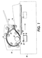
- Figure 1 is an elevational view of a document handler in combination with a scanner or copier.
- the document handler generally indicated as 10, sits atop a main body 20 of the scanner or copier.
- the document handler 10 is positionable or movable relative to the main body 20, typically by a pivot or hinge-like mechanism (not shown) at the back of the scanner.
- a main platen 30 is in effect exposed to the user, so that the user can place a single sheet to have an image thereon recorded.
- a scanner bar 32 Underneath main platen 30, in this embodiment, is what is here called a scanner bar 32.
- a light source 34 and a photosensor array 36 Mounted on scanner bar 32 is a light source 34 and a photosensor array 36, which are arranged so that light emitted by light source 34 is reflected by an image disposed over main platen 30, and the reflected light is recorded by an image receptor, which can be a portion of a xerographic photoreceptor, but in this embodiment is a photosensor array 36.
- Photosensor array 36 typically includes a set of abutted photosensitive chips, and is connected to image processing circuitry downstream (not shown), to record image data in a manner familiar in the art.
- the scanner bar 32 is caused to move, as shown, relative to the main platen 30 to record an entire image on main platen 30.
- the sheets are placed in input tray 12, and are drawn one at a time through path 14 (by one or more motors, not shown, driving the rollers along path 14) past scanner bar 32 and ultimately to an output tray 16.
- path 14 by one or more motors, not shown, driving the rollers along path 14
- scanner bar 32 remains stationary relative to the main body 20, and successive sheets are moved therepast through path 14.
- Pane 50 is light-transmissive solid member through which light from light source 34 and reflected from a portion of a sheet passing through path 14 of document handler 10.
- Pane 50 is rigidly attached to document handler 10, and when the document handler 10 is moved away from the main body 20 (such as to expose main platen 30), the pane 50 travels with document handler 10.
- This arrangement is in contrast with an arrangement such as in the '995 patent described above, in which sheets in the document handler slide against a small platen which is mounted on the main body of the scanner.
- FIG. 2 is a detailed sectional elevational view showing a portion of document handler 10 and main body 20; in this Figure, document handler 10 is shown slightly spaced from the main body 10, as would occur when the document handler 10 is raised slightly.
- a backing roll 52 within document handler 10 is disposed adjacent the pane 50, so that a sheet passing through path 14 is passable between pane 50 and backing roll 52.
- a backing member such as backing roll 52 is urged against pane 50 by suitable means, such as including one or more springs or other resilient members (not shown).
- the urging means can also include a resilient property of the backing member itself.
- the urging means or other resilient properties of members within document hander 10 also contribute to the lessening of vibration around the pane 50, which will have a positive effect on scanning quality.
- An effect of the close contact or urging of a sheet being scanned between pane 50 and backing roll 52 is that the backing roll 52 causes the sheet to retain continuous contact against the pane 50, generally regardless of vibrations within the apparatus.
- the surface of the sheet 50 will remain a fixed distance from the photosensor array 36, ensuring that the sheet will remain precisely focused relative to the photosensor array 36 throughout the duration of the recording by photosensor array 36.
- a lower pane 60 which is disposed adjacent pane 50 when the document handler 10 is lowered to a closed position against main body 20.
- the pane 50 can be in contact with lower pane 60, which is disposed adjacent pane 50 when the document handler 10 is lowered to a closed position against main body 20.
- Lower pane 60 acts as a dust cover for the scanner bar 32, and can also act as a positioning surface for establishing a fixed, predetermined distance between pane 50 and lower pane 60, once again ensuring a known and unchanging distance between scanner bar 32 and a sheet in path 14 sliding over the top surface of pane 50.
- foam backing 58 is in contact with main platen 30.
- main platen 30 and pane 50 and lower pane 60 may, in some embodiments, be made consistent, especially if the scanner bar 32 is effectively movable only in a direction parallel to main platen 30.
- main platen 30 and pane 50 can be substantially co-planar; if lower pane 60 is used as well, main platen 30 can be effectively co-planar with the combination of pane 50 and lower pane 60.
- Such an arrangement is helpful in a design in which main platen 30 is, from the perspective of scanner bar 32, optically equivalent to pane 50 (or pane 50 in combination with lower pane 60).
- scanner bar 32 In a practical implementation, scanner bar 32, with its lamp 34 and photosensor array 36, must be physically protected from dirt, especially when the document handler is raised away from the main body 20. If lower pane 60 is not used, it is desirable to protect the scanner bar 32 in some other way.
- One way is to cause the scanner bar to move to a covered parking position, such as to a location somewhere underneath main platen 30, in response to the document handler 10 being lifted up.
- Another strategy would be to provide a small retractable door (not shown) over scanner bar 32, the door being operated by a spring mechanism or an electromechanical device. The door would extend over scanner bar 32 in response to the document handler 10 being lifted up, through means such as including a switch for sensing the position or latching of document handler 10, as in generally known in the art.
- the illustrated embodiment includes a photosensor array 36, which is mounted on a scanner bar 32, an implementation could be provided with a single-chip photosensor in combination with reductive optics.
Landscapes
- Engineering & Computer Science (AREA)
- Multimedia (AREA)
- Signal Processing (AREA)
- Facsimiles In General (AREA)
- Facsimile Scanning Arrangements (AREA)
- Exposure Or Original Feeding In Electrophotography (AREA)
Abstract
Description
- The present disclosure relates to a document handler for use in a digital copier or scanner.
- Document handlers are devices which draw individual sheets from a stack of sheets, and sequentially allow the image on each sheet to be recorded, typically by a photoreceptor (in a "light-lens" or analog copier) or by a photosensitive device (in a digital copier, scanner, or facsimile). In a common arrangement, a copier has a conventional main platen, on which single sheets can be manually placed, as well as a smaller platen, typically adjacent the main platen, which is used by the document handler when sheets are being passed therethrough. In a typical design, when a single sheet is being recorded through the main platen, the photosensitive device is moved relative to the platen to record the entire image; when the document handler is being used to expose images through the smaller platen, a photosensitive device is typically left stationary under the smaller platen, and the motion of the sheet caused by the hardware within the document handler provides the necessary relative motion of each sheet past the photosensitive device.
- In a practical application, the use of the smaller platen presents difficulties, particularly when the sheet-handling hardware in the document handler is used at high speeds. The vibrations within a document handler at high speeds may cause a sheet moving over the smaller platen to be momentarily out of contact with the smaller platen at a moment of exposure by the photosensitive device. In other words, at high speeds a portion of the moving sheet "bounces" against the smaller platen. This bouncing is particularly common in designs where the document handler is pivotably mounted on the main body of the machine. As photosensitive devices often have poor depth-of-field characteristics, the bouncing away from the smaller platen results in the image on the sheet being momentarily out of focus, leading to unsatisfactory image quality in the recorded image data.
- There is provided an apparatus for recording images on sheets, comprising an image receptor, disposed in a main body of the apparatus, and a document handler, for conveying each of a set of sheets past the image receptor. The document handler is movably mounted relative to the main body of the apparatus. A light-transmissive pane is fixedly mounted relative to the document handler, and is operatively disposed between a sheet and the image receptor when the document handler is moving sheets past the image receptor.
In a further embodiment the apparatus of claim 1 further comprises
a second pane operatively disposed in front of the image receptor, the second pane being mounted within the main body of the apparatus.
In a further embodiment the second pane is disposed a predetermined distance from the pane when the document handler is positioned against the main body of the apparatus.
In a further embodiment the second pane contacts the pane when the document handler is positioned against the main body of the apparatus.
In a further embodiment the image receptor including a photosensitive chip.
In a further embodiment the main body of the apparatus includes a main platen, and wherein the main platen is optically equivalent to the pane, relative to the image receptor when the document handler is positioned against the main body of the apparatus.
In a further embodiment the main body of the apparatus includes a main platen, and wherein the main platen and the pane are substantially co-planar when the document handler is positioned against the main body of the apparatus.
In a further embodiment the apparatus further comprises a main platen in the main body of the apparatus, a lower pane adjacent the pane, and wherein the main platen is optically equivalent to the pane in combination with the lower pane, relative to the image receptor when the document handler is positioned against the main body of the apparatus.
In a further embodiment the apparatus further comprises a main platen in the main body of the apparatus, a lower pane adjacent the pane, and wherein the main platen and the pane in combination with the lower pane are substantially co-planar when the document handler is positioned against the main body of the apparatus. - There is further provided an apparatus for recording images on sheets comprising an image receptor, disposed in a main body of the apparatus, and a document handler, for conveying each of a set of sheets past the image receptor. The document handler is movably mounted relative to the main body of the apparatus. Means are provided for covering the image receptor in response to the document handler being positioned away from the main body of the apparatus.
- In a further embodiment the main body of the apparatus includes a main platen, and the covering means including means for moving the image receptor under the main platen in response to the document handler being positioned away from the main body of the apparatus.
In a further embodiment the apparatus further comprises
a light-transmissive pane fixedly mounted relative to the document handler, and operatively disposed between a sheet and the image receptor when the document handler is moving the sheet past the image receptor. In a further embodiment the apparatus further comprises
means for urging the backing member against the pane.
In a further embodiment the backing member is a backing roll.
In a further embodiment the backing member includes resilient properties.
In a further embodiment the image receptor including a photosensitive chip. -
- Figure 1 is an sectional elevational view of a document handler in combination with a scanner or copier.
- Figure 2 is a detailed sectional elevational view showing a portion of a document handler in combination with a scanner or copier.
-
- Figure 1 is an elevational view of a document handler in combination with a scanner or copier. The document handler, generally indicated as 10, sits atop a
main body 20 of the scanner or copier. As is common in office equipment, thedocument handler 10 is positionable or movable relative to themain body 20, typically by a pivot or hinge-like mechanism (not shown) at the back of the scanner. Further as is common, when thedocument handler 10 is moved away form themain body 20, amain platen 30 is in effect exposed to the user, so that the user can place a single sheet to have an image thereon recorded. - Underneath
main platen 30, in this embodiment, is what is here called ascanner bar 32. Mounted onscanner bar 32 is alight source 34 and aphotosensor array 36, which are arranged so that light emitted bylight source 34 is reflected by an image disposed overmain platen 30, and the reflected light is recorded by an image receptor, which can be a portion of a xerographic photoreceptor, but in this embodiment is aphotosensor array 36.Photosensor array 36 typically includes a set of abutted photosensitive chips, and is connected to image processing circuitry downstream (not shown), to record image data in a manner familiar in the art. When a single sheet or other item is desired to be recorded, thescanner bar 32 is caused to move, as shown, relative to themain platen 30 to record an entire image onmain platen 30. - When the
document handler 10 is used to record images on one or more sheets, the sheets are placed ininput tray 12, and are drawn one at a time through path 14 (by one or more motors, not shown, driving the rollers along path 14) pastscanner bar 32 and ultimately to anoutput tray 16. If adocument handler 10 is capable of "duplexing," that is, sequentially scanning first one side and then the other side of a sheet, the sheet is effectively inverted and passed throughduplexing path 18 for scanning of the second side, in a manner generally familiar in the art. When thedocument handler 10 is used,scanner bar 32 remains stationary relative to themain body 20, and successive sheets are moved therepast throughpath 14. - In the illustrated embodiment, there is associated with
document handler 10 what is here called a "pane" 50. Pane 50 is light-transmissive solid member through which light fromlight source 34 and reflected from a portion of a sheet passing throughpath 14 ofdocument handler 10. Pane 50 is rigidly attached todocument handler 10, and when thedocument handler 10 is moved away from the main body 20 (such as to expose main platen 30), thepane 50 travels withdocument handler 10. This arrangement is in contrast with an arrangement such as in the '995 patent described above, in which sheets in the document handler slide against a small platen which is mounted on the main body of the scanner. - Figure 2 is a detailed sectional elevational view showing a portion of
document handler 10 andmain body 20; in this Figure,document handler 10 is shown slightly spaced from themain body 10, as would occur when thedocument handler 10 is raised slightly. Abacking roll 52 withindocument handler 10 is disposed adjacent thepane 50, so that a sheet passing throughpath 14 is passable betweenpane 50 andbacking roll 52. In one embodiment, a backing member such asbacking roll 52 is urged againstpane 50 by suitable means, such as including one or more springs or other resilient members (not shown). The urging means can also include a resilient property of the backing member itself. The urging means or other resilient properties of members withindocument hander 10 also contribute to the lessening of vibration around thepane 50, which will have a positive effect on scanning quality. - An effect of the close contact or urging of a sheet being scanned between
pane 50 andbacking roll 52 is that thebacking roll 52 causes the sheet to retain continuous contact against thepane 50, generally regardless of vibrations within the apparatus. By retaining continuous contact againstpane 50, the surface of thesheet 50 will remain a fixed distance from thephotosensor array 36, ensuring that the sheet will remain precisely focused relative to thephotosensor array 36 throughout the duration of the recording byphotosensor array 36. - Also shown in Figure 2, associated with
main body 20, is alower pane 60, which is disposedadjacent pane 50 when thedocument handler 10 is lowered to a closed position againstmain body 20. In one possible embodiment, thepane 50 can be in contact withlower pane 60, which is disposedadjacent pane 50 when thedocument handler 10 is lowered to a closed position againstmain body 20.Lower pane 60 acts as a dust cover for thescanner bar 32, and can also act as a positioning surface for establishing a fixed, predetermined distance betweenpane 50 andlower pane 60, once again ensuring a known and unchanging distance betweenscanner bar 32 and a sheet inpath 14 sliding over the top surface ofpane 50. When thedocument handler 10 is lowered againstmain body 20,foam backing 58 is in contact withmain platen 30. - Since
scanner bar 32 is used to record hard-copy images on eithermain platen 30 or through pane 50 (and possibly throughlower pane 60 as well), the optical layout and positioning ofmain platen 30 andpane 50 andlower pane 60 may, in some embodiments, be made consistent, especially if thescanner bar 32 is effectively movable only in a direction parallel tomain platen 30. For example, when thedocument handler 10 is lowered againstbody 20,main platen 30 andpane 50 can be substantially co-planar; iflower pane 60 is used as well,main platen 30 can be effectively co-planar with the combination ofpane 50 andlower pane 60. Such an arrangement is helpful in a design in whichmain platen 30 is, from the perspective ofscanner bar 32, optically equivalent to pane 50 (orpane 50 in combination with lower pane 60). - In a practical implementation,
scanner bar 32, with itslamp 34 andphotosensor array 36, must be physically protected from dirt, especially when the document handler is raised away from themain body 20. Iflower pane 60 is not used, it is desirable to protect thescanner bar 32 in some other way. One way is to cause the scanner bar to move to a covered parking position, such as to a location somewhere underneathmain platen 30, in response to thedocument handler 10 being lifted up. Another strategy would be to provide a small retractable door (not shown) overscanner bar 32, the door being operated by a spring mechanism or an electromechanical device. The door would extend overscanner bar 32 in response to thedocument handler 10 being lifted up, through means such as including a switch for sensing the position or latching ofdocument handler 10, as in generally known in the art. - Although the illustrated embodiment includes a
photosensor array 36, which is mounted on ascanner bar 32, an implementation could be provided with a single-chip photosensor in combination with reductive optics.
Claims (10)
- An apparatus for recording images on sheets, comprising:an image receptor, disposed in a main body of the apparatus;a document handler, for conveying each of a set of sheets past the image receptor, the document handler being movably mounted relative to the main body of the apparatus; anda light-transmissive pane fixedly mounted relative to the document handler, and operatively disposed between a sheet and the image receptor when the document handler is moving the sheet past the image receptor.
- The apparatus of claim 1, further comprising
a backing member within the document handler, adjacent the pane. - The apparatus of claim 2, further comprising
means for urging the backing member against the pane. - The apparatus of claim 2, wherein the backing member is a backing roll.
- The apparatus of claim 2, wherein the backing member includes resilient properties.
- The apparatus of claim 1, further comprising
means for covering the image receptor when the document handler is positioned away from the main body of the apparatus. - The apparatus of claim 6, the covering means including means for moving the image receptor to an effectively covered position when the document handler is positioned away from the main body of the apparatus.
- The apparatus of claim 1, wherein the main body of the apparatus includes a main platen, and further comprising means for moving the image receptor under the main platen in response to the document handler being positioned away from the main body of the apparatus.
- An apparatus for recording images on sheets, comprising:an image receptor, disposed in a main body of the apparatus;a document handler, for conveying each of a set of sheets past the image receptor, the document handler being movably mounted relative to the main body of the apparatus; andmeans for covering the image receptor in response to the document handler being positioned away from the main body of the apparatus.
- The apparatus of claim 9, the covering means including means for moving the image receptor to an effectively covered position when the document handler is positioned away from the main body of the apparatus.
Applications Claiming Priority (2)
| Application Number | Priority Date | Filing Date | Title |
|---|---|---|---|
| US721850 | 2003-11-25 | ||
| US10/721,850 US20050111059A1 (en) | 2003-11-25 | 2003-11-25 | Document handler with improved optics |
Publications (1)
| Publication Number | Publication Date |
|---|---|
| EP1536625A1 true EP1536625A1 (en) | 2005-06-01 |
Family
ID=34465677
Family Applications (1)
| Application Number | Title | Priority Date | Filing Date |
|---|---|---|---|
| EP04027930A Withdrawn EP1536625A1 (en) | 2003-11-25 | 2004-11-24 | Document handler with improved sheet transport at scanning position |
Country Status (5)
| Country | Link |
|---|---|
| US (1) | US20050111059A1 (en) |
| EP (1) | EP1536625A1 (en) |
| JP (1) | JP2005160068A (en) |
| CN (1) | CN1621953A (en) |
| BR (1) | BRPI0405140A (en) |
Families Citing this family (4)
| Publication number | Priority date | Publication date | Assignee | Title |
|---|---|---|---|---|
| JP2007088919A (en) * | 2005-09-22 | 2007-04-05 | Fuji Xerox Co Ltd | Original reader and image forming apparatus |
| US9781283B1 (en) | 2016-05-25 | 2017-10-03 | Xerox Corporation | Document handler having integrated platen and fully internal CVT path |
| WO2020027835A1 (en) * | 2018-08-01 | 2020-02-06 | Hewlett-Packard Development Company, L.P. | Modular scanner subassembly |
| WO2021154255A1 (en) * | 2020-01-30 | 2021-08-05 | Hewlett-Packard Development Company, L.P. | Print media detection with scanner bar |
Citations (7)
| Publication number | Priority date | Publication date | Assignee | Title |
|---|---|---|---|---|
| US5339139A (en) * | 1993-10-12 | 1994-08-16 | Xerox Corporation | Document feeder with positive document removal from imaging platen |
| JPH1023227A (en) * | 1996-07-03 | 1998-01-23 | Ricoh Co Ltd | Image reading device |
| US20020054382A1 (en) * | 2000-08-25 | 2002-05-09 | Murata Kikai Kabushiki Kaisha | Duplex automatic document feeder |
| EP1309168A2 (en) * | 2001-10-26 | 2003-05-07 | Canon Kabushiki Kaisha | Structure for preventing extraneous light from entering image reading apparatus |
| US20030090747A1 (en) * | 2001-11-13 | 2003-05-15 | Po-Hua Fang | Depth of field adjustment device and method for an automatic document feeder |
| US6593995B1 (en) * | 2002-04-12 | 2003-07-15 | Xerox Corporation | Dual mode document scanner with variable platen level transition |
| US20030214680A1 (en) * | 2002-05-14 | 2003-11-20 | Mitsuhiro Sugeta | Image reading apparatus, control method therefor, and program |
Family Cites Families (34)
| Publication number | Priority date | Publication date | Assignee | Title |
|---|---|---|---|---|
| US4849788A (en) * | 1988-06-16 | 1989-07-18 | Xerox Corporation | Automatic dual mode document registration and edge guide |
| JPH0229152A (en) * | 1988-07-19 | 1990-01-31 | Matsushita Electric Ind Co Ltd | Original reading device |
| JPH05122451A (en) * | 1991-10-24 | 1993-05-18 | Seiko Epson Corp | Image skyana |
| US5328163A (en) * | 1991-11-07 | 1994-07-12 | Konica Corporation | Recording sheet feeding device |
| JP2958839B2 (en) * | 1992-06-02 | 1999-10-06 | 三田工業株式会社 | Automatic document feeder |
| US5953574A (en) * | 1993-12-17 | 1999-09-14 | Canon Kabushiki Kaisha | Sheet feeding apparatus and image forming apparatus |
| JPH07199551A (en) * | 1993-12-29 | 1995-08-04 | Toshiba Corp | Automatic document feeder and image forming apparatus having this automatic document feeder |
| JP3163882B2 (en) * | 1994-01-19 | 2001-05-08 | ミノルタ株式会社 | Scanning device |
| US5610731A (en) * | 1994-04-18 | 1997-03-11 | Ricoh Company, Ltd. | Image scanner having contact-type image sensor movable under automatic document feeder |
| US5488464A (en) * | 1994-05-31 | 1996-01-30 | Xerox Corporation | Constant velocity transport for electronic document imaging |
| US5680204A (en) * | 1994-10-12 | 1997-10-21 | Xerox Corporation | Dual scanning electronic reprographic document handler |
| JP3388114B2 (en) * | 1996-11-15 | 2003-03-17 | 京セラミタ株式会社 | Document feeder |
| US6384940B1 (en) * | 1997-04-21 | 2002-05-07 | Murata Kikai Kabushiki Kaisha | Facsimile device utilizing process unit for electrophotographic device |
| JP3665831B2 (en) * | 1998-07-14 | 2005-06-29 | コニカミノルタビジネステクノロジーズ株式会社 | Image reading device |
| US6512602B1 (en) * | 1999-04-01 | 2003-01-28 | Avision, Inc. | Guide for a paper feeder |
| US6618575B2 (en) * | 2000-04-20 | 2003-09-09 | Nisca Corporation | Automatic document feeder with a conveying roller and an image reader |
| JP2001343712A (en) * | 2000-05-31 | 2001-12-14 | Fujitsu Ltd | Image input device |
| US6738167B1 (en) * | 2000-07-28 | 2004-05-18 | Kabushiki Kaisha Toshiba | Image reading apparatus and document feeding method in image reading apparatus |
| TW478698U (en) * | 2000-09-21 | 2002-03-01 | Avision Inc | Scanner with the calibration function for dual-face scan |
| US6874778B2 (en) * | 2000-10-31 | 2005-04-05 | Canon Kabushiki Kaisha | Sheet feeding apparatus and image forming apparatus provided with same |
| US6595512B2 (en) * | 2000-12-06 | 2003-07-22 | Xerox Corporation | Constant force sheet feeder |
| JP3576966B2 (en) * | 2000-12-07 | 2004-10-13 | キヤノン株式会社 | Image reading apparatus and reading position setting method |
| JP2002348052A (en) * | 2001-03-21 | 2002-12-04 | Ricoh Co Ltd | Automatic document feeder and image forming apparatus |
| JP3720725B2 (en) * | 2001-04-17 | 2005-11-30 | キヤノン株式会社 | Image forming apparatus |
| US6947187B2 (en) * | 2001-05-24 | 2005-09-20 | Hewlett-Packard Development Company, L.P. | Apparatus and method for calibrating a scanner with a document feeder |
| JP3851114B2 (en) * | 2001-06-12 | 2006-11-29 | ニスカ株式会社 | Automatic document feeder |
| JP4422929B2 (en) * | 2001-07-31 | 2010-03-03 | キヤノン株式会社 | Paper feeding device, image forming apparatus including the same, and image reading apparatus |
| TW534090U (en) * | 2001-11-15 | 2003-05-21 | Silitek Corp | Paper feeder |
| JP2004043178A (en) * | 2002-05-23 | 2004-02-12 | Ricoh Co Ltd | Automatic document feeder and image processing device |
| JP3626943B2 (en) * | 2002-06-24 | 2005-03-09 | ニスカ株式会社 | Automatic document feeder |
| US7021618B2 (en) * | 2002-06-24 | 2006-04-04 | Nisca Corporation | Automatic document feeding apparatus and document reading apparatus |
| JP2004048265A (en) * | 2002-07-10 | 2004-02-12 | Ricoh Co Ltd | Document reading device and image forming device |
| US7099618B2 (en) * | 2002-10-01 | 2006-08-29 | Brother Kogyo Kabushiki Kaisha | Paper discharge tray |
| JP2004173165A (en) * | 2002-11-22 | 2004-06-17 | Canon Inc | Image reading device |
-
2003
- 2003-11-25 US US10/721,850 patent/US20050111059A1/en not_active Abandoned
-
2004
- 2004-11-18 JP JP2004334038A patent/JP2005160068A/en active Pending
- 2004-11-23 BR BR0405140-8A patent/BRPI0405140A/en not_active IP Right Cessation
- 2004-11-24 EP EP04027930A patent/EP1536625A1/en not_active Withdrawn
- 2004-11-24 CN CNA2004100953973A patent/CN1621953A/en active Pending
Patent Citations (7)
| Publication number | Priority date | Publication date | Assignee | Title |
|---|---|---|---|---|
| US5339139A (en) * | 1993-10-12 | 1994-08-16 | Xerox Corporation | Document feeder with positive document removal from imaging platen |
| JPH1023227A (en) * | 1996-07-03 | 1998-01-23 | Ricoh Co Ltd | Image reading device |
| US20020054382A1 (en) * | 2000-08-25 | 2002-05-09 | Murata Kikai Kabushiki Kaisha | Duplex automatic document feeder |
| EP1309168A2 (en) * | 2001-10-26 | 2003-05-07 | Canon Kabushiki Kaisha | Structure for preventing extraneous light from entering image reading apparatus |
| US20030090747A1 (en) * | 2001-11-13 | 2003-05-15 | Po-Hua Fang | Depth of field adjustment device and method for an automatic document feeder |
| US6593995B1 (en) * | 2002-04-12 | 2003-07-15 | Xerox Corporation | Dual mode document scanner with variable platen level transition |
| US20030214680A1 (en) * | 2002-05-14 | 2003-11-20 | Mitsuhiro Sugeta | Image reading apparatus, control method therefor, and program |
Non-Patent Citations (1)
| Title |
|---|
| PATENT ABSTRACTS OF JAPAN vol. 1998, no. 05 30 April 1998 (1998-04-30) * |
Also Published As
| Publication number | Publication date |
|---|---|
| JP2005160068A (en) | 2005-06-16 |
| US20050111059A1 (en) | 2005-05-26 |
| BRPI0405140A (en) | 2005-07-19 |
| CN1621953A (en) | 2005-06-01 |
Similar Documents
| Publication | Publication Date | Title |
|---|---|---|
| TW527817B (en) | Image sensor and image reading apparatus | |
| US9686422B2 (en) | Image scanner having a reader and image forming apparatus incorporating same | |
| EP1309168A2 (en) | Structure for preventing extraneous light from entering image reading apparatus | |
| JP2003221145A (en) | Document conveying device, image reading device, and image forming device | |
| JP5688929B2 (en) | Image reading apparatus and image forming apparatus having the same | |
| US20120206779A1 (en) | Illuminating device, image reading apparatus including the illuinating device, and image forming apparatus including the image reading apparatus | |
| JP6184392B2 (en) | Image reading apparatus and image forming apparatus | |
| US20140198357A1 (en) | Image reading device and image forming apparatus therewith | |
| US20050111059A1 (en) | Document handler with improved optics | |
| JP2015027070A (en) | Image reading apparatus, document conveying apparatus, and image forming apparatus | |
| US7457006B2 (en) | Calibration system for a scanner for recording images from sheets | |
| AU2010227026B2 (en) | Image forming apparatus | |
| JPH11289430A (en) | Image reading device and image forming device | |
| JPH0646219A (en) | Image information reader | |
| JP6931483B2 (en) | Sheet transfer device, image reading device and image forming device | |
| US7710614B2 (en) | Image forming device | |
| JP2005022805A (en) | Sheet conveying apparatus and reading apparatus | |
| JP3224493B2 (en) | Image reading device | |
| JP6157855B2 (en) | Image reading apparatus and image forming apparatus | |
| JP6037225B2 (en) | Image reading apparatus and image forming apparatus | |
| JP2005286586A (en) | Document reader | |
| JP3833147B2 (en) | Document reader | |
| JP3311374B2 (en) | Book manuscript reading device | |
| JP2003241328A (en) | Image reading device | |
| JP6794720B2 (en) | Image reader and image forming device |
Legal Events
| Date | Code | Title | Description |
|---|---|---|---|
| PUAI | Public reference made under article 153(3) epc to a published international application that has entered the european phase |
Free format text: ORIGINAL CODE: 0009012 |
|
| AK | Designated contracting states |
Kind code of ref document: A1 Designated state(s): AT BE BG CH CY CZ DE DK EE ES FI FR GB GR HU IE IS IT LI LU MC NL PL PT RO SE SI SK TR |
|
| AX | Request for extension of the european patent |
Extension state: AL HR LT LV MK YU |
|
| 17P | Request for examination filed |
Effective date: 20051201 |
|
| AKX | Designation fees paid |
Designated state(s): DE FR GB |
|
| 17Q | First examination report despatched |
Effective date: 20060202 |
|
| GRAP | Despatch of communication of intention to grant a patent |
Free format text: ORIGINAL CODE: EPIDOSNIGR1 |
|
| RTI1 | Title (correction) |
Free format text: IMAGE SCANNING APPARATUS WITH DUST PROTECTION DOOR FOR IMAGE SENSOR |
|
| STAA | Information on the status of an ep patent application or granted ep patent |
Free format text: STATUS: THE APPLICATION IS DEEMED TO BE WITHDRAWN |
|
| 18D | Application deemed to be withdrawn |
Effective date: 20090402 |