[Technical Field]
This invention relates to control of a servo motor
for driving a machine such as a direct-acting table, an
X-Y table or a robot, and more particularly to (1) a gain
adjusting method for a servo control device in a machine
which can operate even when an oscillation characteristic
is changed as a result that the supporting condition and
posture of a machine have been changed by the operation
of the machine; (2) where the servo control gain in a
servo control device is automatically set, in a method
for extracting a control gain from the response of the
oscillation by increasing the control gain, to a gain
adjusting method for suppressing the control gain from
the oscillation during stopping; (3) similarly, where
the servo control gain in a servo control device is
automatically set, in a method for detecting the limited
value of a servo control gain by detecting excitation
and oscillation by an exciting member particularly in
a machine, to a gain adjusting method for selecting a
control method such as an observer to acquire an optimum
control; and (4) to a gain control method of increasing
the gain from the information obtained when run by
generating a command by an external operation and from
a sequence after the sequence of tuning has been built
into a servo control device.
[Background Art]
A conventional general servo control device, as
shown in Fig. 15, includes a servo motor 6 to be controlled,
an inverter section for driving the motor 6 by switching
transistors 5 through a base drive circuit 4, a CPU 2
for operating position control and speed control, and
a current amplifier 3 for issuing a driving command to
the base drive circuit 4 in response to the current command
received from the CPU 2.
An example of the gain control method in the servo
control device is a "system for oscillation detection
and speed loop gain automatic adjustment in a servo system"
disclosed in JP-A-Hei2-261083. In this case, the servo
motor is subjected to stick-stepping so that it is also
rotated in an opposite direction. This is repeated to
increase the speed loop gain continuously, thereby
generating oscillation. The acceleration change
obtained by differentiating an actual speed change in
the servo motor is frequency-analyzed to detect the
oscillation in the servo system. While the oscillation
frequency thus obtained and a prescribed reference
frequency are being compared with each other, the speed
loop gain is adjusted so that the oscillation frequency
accords with the reference frequency and becomes a value
in vicinity thereof.
Further, in an "automatic adjustment servo control
device" disclosed in JP-A-Hei6-242833, in order that the
servo motor can follow a change in a load machine connected
thereto, the operation of the servo motor is started with
an optimum parameter under a predetermined standard load.
On the basis of the observation for a predetermined period
from when the operation has been started, by integrating
a difference between the deviation counter curve during
the period and a standard model of the deviation counter
curve when the optimum parameter based on a prescribed
standard load is used, an actual load is estimated. By
referring to a table showing various loads previously
created and stored and the corresponding optimum control
parameters, the parameter can be changed into the optimum
control parameter corresponding to the actual load.
However, as regards the prior arts described above,
in the case of JP-A-Hei2-261083, the gain is increased
to oscillate the servo system, and the gain when the servo
system is oscillated is set as a maximum value.
Specifically, since the parameter adjustment is
carried out at the increased gain, there is no margin
of the adjustment. Further, since the gain oscillated
at a certain place (or position) of a machine is computed,
if the place of the machine is shifted, the gain also
varies so that there are differences in the gain according
to the place of the machine. At a certain position of
the machine, vibration occurs.
Further, in the case of JP-A-Hei6-242833, since the
observation must be continued for a prescribed period,
differences cannot be suppressed according to the place.
Further, since only the load varies, accurate adjustment
of the parameter cannot be performed.
Therefore, a first object of this invention is to
provide a gain adjusting method for a servo control device
capable of surely making auto-tuning with no difference
according to a place by performing the gain adjustment
not only at a specific position of a machine but also
over an entire movable range thereof in a servo motor
for driving the machine and a servo control device.
Further, in the case of JP-A-Hei2-261083, the gain
is increased to oscillate the servo system, and the gain
when the servo system is oscillated is set as a maximum
value. Namely, taking the machine into consideration at
this time, the gain is set at the maximum value or adjusted.
Further, in the case of JP-A-Hei6-24283, the state of
the load was estimated from the deviation counter, and
the control parameter was selected from the state of the
load to adjust the controlled gain. Namely, the gain for
the position control or speed control was determined
according to the load.
Meanwhile, in the prior arts described above, since
the oscillation can be observed only after the gain is
increased to realize the oscillating state, it takes a
long time for the adjustment of the gain. Specifically,
while the machine stops, the machine does not oscillate
immediately after the gain has been increased. Further,
also while the machine runs, it starts to oscillate from
points where the oscillation is likely to occur, as
indicated by A and B in Fig. 16(i). In other words, since
the machine is subjected to friction or load and they
act to suppress the oscillation, unless there is a great
chance, the oscillation does not occur. Thus, as shown
in Fig. 16(ii), in order to cause oscillation easily,
it is necessary to expect the time delay until the
oscillation starts by issuing a long command at a high
speed for each time, thereby increasing the gain slowly
so that it is increased only once by a single command.
This presents a problem that it takes a long time for
the maximum gain to be detected.
Fig. 17 shows the case where the above matter is
ignored and the gain has been increased quickly. At timing
t1, the gain has been already increased excessively so
that at timing t2 when the oscillation is detected, the
gain is increased more excessively. Therefore, even when
the gain is decreased, as indicated by C in Fig. 17, the
oscillation does not stop easily so that the machine
vibrates greatly. Also in the case where the machine does
not oscillate but a little vibrates, there is slight
vibration or noise. This was problematic.
In view of the above matter, a second object of this
invention is to vibrate the machine by increasing the
gain but to suppress slight vibration while the machine
stops, thereby stabilizing the machine.
Further, a third object of this invention is to
provide an optimum control method which vibrates the
machine by increasing the gain but detects the vibration
early to stop the machine instantaneously, thereby not
vibrating the machine greatly.
In the prior arts described above, since the
controller issued a command, the oscillation or the
maximum value of the gain was decided by the controller,
thereby performing automatic tuning of the gain. However,
because of the data transfer delay between the controller
and the servo and since the interval of the processing
scan in the controller is later than in the servo, the
above decision cannot be made instantaneously to take
a long time. Further, even when the oscillation occurs
because of a difference in machines, the operation of
decreasing the gain cannot be carried out instantaneously.
The invention disclosed in JP-A-Hei6-24283 presents
a problem that the above instantaneous decision cannot
be made.
In view of this matter, a fourth object of this
invention is to determine oscillation in real time by
installing the operation sequence of auto-tuning actuated
by an external operation into a servo, thereby
automatically adjusting servo gain.
[Disclosure of the Invention]
In order to attain the above object, the invention
described in claim 1 is a gain adjusting method for a
servo control device providing speed control of inputting
a difference between speed feedback supplied from a servo
motor and a command value to output a torque command,
characterized in that after a speed loop gain is increased
to detect vibration at each of a plurality of points moved
over a movable range of a machine, the speed loop gain
is decreased to detect the gain when the vibration becomes
still as a maximum value, thereby providing a set gain
value corresponding to a machine.
In the gain adjusting method for a servo control
device, after the speed loop gain is increased to detect
vibration at each of points moved over a movable range
of a machine, the speed loop gain is decreased to detect
the gain when the vibration becomes still as a maximum
value for gain adjustment. Since the gain where the
vibration becomes still is used, the margin for the
vibration is given. Changes according to the places of
a machine can be suppressed.
In accordance with the invention described in claim
2, the set gain value is set at a minimum value of gain
values detected at the plurality of points.
In this gain adjusting method for the servo control
device, the loop gain is adjusted at each of adjustment
points over the movable range of the machine. The minimum
value of the loop gains detected at the adjustment points
is determined as the entire loop gain. For this reason,
the gain is stable for the vibration and changes thereof
according to the places of the machine can be suppressed.
In accordance with the invention of a method for
adjusting a controlled gain described in claim 3, in a
device for driving a servo motor provided with a vibration
detecting member for detecting vibration of a control
system, running such as acceleration/deceleration is
performed at an increased controlled gain, and when the
vibration is detected by the vibration detecting member
while the control system stops, decreasing the controlled
gain.
In accordance with the invention described in claim
4, in the method for adjusting a controlled gain according
to claim 3, the vibration during stopping is detected
from torque in the normal running is detected, and when
the vibration is detected by the vibration detecting
member, the controlled gain is decreased.
In accordance with the invention described in claim
5, in the method for adjusting a controlled gain according
to claim 3, the vibration during stopping in the normal
running is detected, and when the vibration is detected
at an increased gain, the gain at this time is determined
as a maximum gain.
Through these members, the normal running is
performed, and by adjusting the controlled gain, the
vibration during stopping and noise can be suppressed.
In accordance the invention of acquiring an optimum
control method described in claim 6, in a servo control
device for driving a servo motor which is provided with
a vibration detecting member for detecting vibration in
a control system and an exciting member for adding, to
a torque command, simulated disturbance torque giving
vibration at a predetermined level at an increased
controlled gain, a method for adjusting a controlled gain,
wherein a control method such as an observer is selected
as the optimum control method in a limited gain extracting
method including the steps of determining as a limited
gain the gain when the vibration exceeding the
predetermined level is detected by the vibration detecting
member, repeating the processing of giving the excitation
having an adjusted magnitude by the exciting member,
detecting the vibration by the vibration detecting member,
and adding the simulated disturbance torque while
increasing the controlled gain until the vibration at
the predetermined level is detected.
In accordance with the invention described in claim
7, in the method for adjusting a controlled gain according
to claim 6, in selecting the control method such as the
observer to provide an optimum control method, the control
method with a higher value of the limited gain is selected
as an optimum control method.
In accordance with the invention described in claim
8, in the method for adjusting a controlled gain according
to claim 6, and in the method for selecting the control
method such as the observer to provide an optimum control
method, wherein the control method with a higher value
of the limited gain is selected as an optimum control
method, if pertinent control methods have equal limited
gains, by increasing the simulated disturbance torque,
the margin of the controlled gain where the vibration
at a predetermined level is detected, and the control
method providing a larger margin is selected.
Through the above members, the machine is surely
vibrated at the controlled gain suited thereto to acquire
the maximum gain. Thus, the optimum control method can
be automatically selected and adjusted.
In accordance with the invention of the gain
adjusting method described in claim 9, in a gain adjustment
method for a servo control device providing speed control
of inputting a difference between speed feedback supplied
from a motor and a command value to output a torque command,
tuning is implemented in such a manner that a servo control
device for driving a servo motor is run by generating
a command by an external operation of an operator and
from a sequence of tuning build in the device, and the
gain is adjusted by the information obtained upon running.
Through the above members, since the sequence by
the external operation is built into the servo control
device, the gain can be detected in real time and also
hence can be instantaneously determined from the
information obtained at this time when any event occurs.
Further, even when the vibration occurs because of
differences in machines, it can be dealt with
instantaneously.
[Brief Description of the Drawings]
Fig. 1 is a view showing the configuration of a servo
control device commonly related to each of various
embodiments of this invention.
Fig. 2 is a control block diagram of the servo control
device shown in Fig. 1.
Fig. 3 is a timing chart of a gain increased to cause
vibration and thereafter decreased and a torque.
Fig. 4 is a view showing a movable range of a machine
which is driven by the servo control device shown in Fig.
1.
Fig. 5 is a control block diagram relative to a second
embodiment and a third embodiment.
Fig. 6 is a measurement timing chart of a speed
command, a speed, a torque waveform and a vibration level
during normal running.
Fig. 6(i) illustrates timings of detection of a
vibration level during stopping.
Fig. 6(ii) illustrates extension of the vibration
level during stopping.
Fig. 6(iii) illustrates timings of adjustment of
a control gain.
Fig. 7 is a graph showing the relationship between
a speed loop gain and the amplitude of a torque during
stopping.
Fig. 8 is a schematic flowchart of adjusting a control
gain.
Fig. 9 is a measurement timing chart of a speed
command, a speed, a torque waveform and a vibration level
during normal running.
Fig. 10 is a timing chart of generating vibration
by increasing the control gain and extracting the
decreased gain and the maximum gain when the vibration
is generated.
Fig. 11 is a schematic flowchart of extracting the
maximum gain in this invention.
Fig. 12 is a view showing the construction of a servo
control device for explaining the operation according
to a fourth embodiment.
Fig. 13 is a view showing an exemplary sequence.
Fig. 14 is a waveform timing chart of a gain and
torque or speed.
Fig. 15 is a view showing a conventional servo control
device.
Fig. 16(i) is a timing chart of vibration during
the normal running.
Fig. 16 (ii) is a timing chart of increasing the gain
during the normal running.
Fig. 17 is a timing chart of abruptly increasing
the gain to cause great oscillation in adjustment during
the normal running.
Reference numerals in the drawings are as follows.
- 1:
- vibration detecting member
- 2:
- microcomputer
- 3:
- amplitude
- 4:
- base drive circuit
- 5:
- power transistor module
- 6:
- motor
- 11:
- speed control block
- 12:
- 1/JS
- 21:
- table
- 22:
- ball screw
- 51:
- position loop gain
- 52:
- speed control
- 53:
- 1/JS corresponding to a motor and load
- 54:
- integration
- 61:
- operator
[Best Mode for Carrying Out the Invention]
Now referring to the drawings, an explanation will
be given of the first embodiment of this invention.
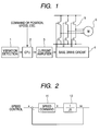
Fig. 1 is a view showing the configuration of a servo
control device according to an embodiment of this
invention.
Fig. 2 is a control block diagram of the servo control
device shown in Fig. 1.
Fig. 3 is a timing chart of a gain increased to cause
vibration and thereafter decreased and a torque.
Fig. 4 is a view showing a movable range of a machine
which is driven by the servo control device shown in Fig.
1.
In Fig. 1, reference numeral 1 denotes a vibration
detecting circuit; 2 a CPU; 3 a current amplifier; 4 a
base drive circuit; 5 a power transistor module; and 6
a motor.
Fig. 2 is a block diagram of speed control. Reference
numeral 11 denotes speed control unit. For example, in
the case of the speed control, in response to a speed
command, the speed control outputs a torque command having
adjustment gains such as a speed loop gain K and an
integration time constant T to drive 1/JS (12)
corresponding to a motor and a load. Thereafter, a speed
feedback ω and the speed command are supplied to a
subtracter, thereby performing the speed control to remove
a speed deviation.
Fig. 3 is a timing chart of a loop gain and torque
waveform.
When the gain is increased from G0 to G1, as seen
from the lower part of Fig. 3, the torque or speed
oscillates. Then, the gain is lowered to G2, thereby
adjusting the torque or speed into a stationary state.
In this case, the detection of vibration may be
performed by a system as disclosed in the prior art
JP-A-Hei2-261083 in which the servo motor is placed in
a stick-step state (repetition of normal rotation and
reverse rotation) to increase the gain of a parameter
and thereafter the amplitude and frequency are analyzed
using an FET by CPU to detect the vibration, or otherwise
a method in which a difference between torque command
values T(i) and T (I - 1) for each of sampling cycles
is acquired and the number of times of the sign within
a predetermined period is estimated through statistical
operation. Further, an integrating gain and torque
filter may be changed with the gain.
Further, at a place where the gain is not increased,
the vibration of a machine is suppressed using the filter.
Next, the operation will be explained.
The microcomputer 2 receives a command of a position
or speed from an external controller. For example, in
the case of the speed command, the microcomputer 2 performs
the speed control like the speed control 11 as shown in
a block diagram of Fig. 2. By the output current command
or an output of current control, the power transistors
5 are switched through the base drive circuit 4 as shown
in Fig. 1 to control the motor 6, thereby driving a machine
such as a ball screw 22 or a table 21 as shown in Fig.
4.
The vibration detecting circuit 1 detects the
vibration when it exceeds a predetermined level thereof.
The adjustment is implemented at a plurality of adjustment
points over a movable range of the machine as shown in
Fig. 4. First, at each measurement point, as shown in
Fig. 3, the adjustment is made in such a fashion that
if the vibration is detected in the process of increasing
the gain from G0 to G1, the gain is decreased so that
gain G2 when the vibration becomes still is set as the
maximum value. Such gain adjustment is implemented at
each of the adjustment points moved over the entire movable
range of the machine.
Further, the gain adjustment is implemented over
the entire movable range. A minimum value of the
adjustment gains at the adjustment points is set as the
entire adjustment gain. If the gain in a speed control
system is set taking the characteristic of the machine
or confirming it again, the gain adjustment is more
practical.
Incidentally, in the speed control 11, in the case
of a simple proportional-plus-integral control (PI
control), the gain is expressed by
K/(1 + TiS)
where
- K:
- speed loop gain
- Ti:
- integration time constant
However, in the control method such as IP control
or PID control other than the proportional-plus-integral
(PI) control, the gain adjustment can be implemented in
the same manner.
As described above, in accordance with the first
embodiment, by implementing the gain adjustment in such
a manner that the speed loop gain is increased to detect
vibration at each of points moved over a movable range
of a machine, the gain where the vibration becomes still
is detected as a maximum value of adjusted gains, and
a minimum value of these adjusted gains is adopted as
the entire adjusted gain, it is possible to realize
stabilized adjustment with a margin for the vibration,
thus suppressing changes according to the places of the
machine.
The above gain adjustment can be also applied to
the adjustment of the machine itself.
Next, referring to a control block diagram of Fig.
5, a timing chart of Fig. 6, a maximum gain extracting
timing chart of Fig. 7 and a flowchart of Fig. 8, an
explanation will be given of the operation according to
the second embodiment in the circuit in Fig. 1.
The microcomputer 2 receives a command of a position
or speed from an external controller. For example, in
the case of the speed command, the microcomputer 2 performs
the speed control. By the output current command or an
output of current control, the power transistors 5 are
driven through the base drive circuit 4 to control the
motor 6.
The vibration detecting circuit 1 detects the
vibration when a vibration component contained in a
during-stopping torque command exceeds a predetermined
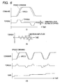
level. Running is done with a low gain as shown in Fig.
6 (i), and as a detection level of vibration, the amplitude
level of torque vibration during stopping in the normal
running is detected as shown in Fig. 6(ii). The detection
level of vibration may be e.g. about five times as large
as the vibration level at the low gain.
For detection of the controlled gain, as shown in
Fig. 6(i), first, the amplitude of the torque is observed
during stopping at a low gain. Next, at a gain increased
as shown in Fig. 6(iii), running is done. During the
stopping thereof, the amplitude of the torque is measured.
If the amplitude is larger than e.g. about five times
as large as that at the low gain, the controlled gain
is adopted as a maximum gain. If the gain is gradually
increased, great oscillation does not occur, but slight
vibration may occur during the stopping. Automated gain
adjustment is carried out so as to suppress the vibration.
The relationship between the speed loop gain and
the amplitude of vibration of the torque when the vibration
occurs during the stopping is shown in Fig. 7. As seen
from Fig. 7, when the speed loop gain exceeds a certain
value, the amplitude of vibration of the torque abruptly
increases. Thus, the gain when the amplitude of torque
has abruptly increased can be determined as the maximum
gain.
An explanation will be given of a series of
operations.
First, at flow 1 in Fig. 8, the running such as
acceleration/deceleration is done to detect the vibration
level of torque during stopping. At flow 2 in Fig. 8,
whether or not the controlled gain is within a limited
value is determined. This limited value may be decided
in terms of the characteristic of the machine or by
measurement. If the controlled gain is at the limited
value, it is determined as the maximum value, thereby
ending the adjustment of gain. If the controlled gain
is within the limited value, the following adjustment
of gain proceeds. At flow 3 in Fig. 8, the running such
as acceleration/deceleration is done. At flow 4 in Fig.
8, whether or not the controlled gain exceeds the level
of torque vibration during stopping is determined. If
exceeds, at flow 5 in Fig. 8, the controlled gain is
decreased. The gain thus decreased is determined as the
maximum gain, thereby ending the adjustment of gain. In
not exceed, the controlled gain is increased. The
operations at flows 2 to 4 in Fig. 8 are repeated. In
this way, the controlled gain is adjusted.
The vibration detecting circuit 1 (Fig. 1) may be
realized by the microcomputer 2. Further, the
integration gain or torque filter may be changed with
the controlled gain.
In accordance with the second embodiment, by
adjusting the controlled gain through the normal running,
occurrence of the vibration or noise during stopping can
be suppressed, thereby stabilizing the controlled gain.
Next, referring to a control block diagram of Fig.
5, a timing chart of Fig. 9, a maximum gain extracting
timing chart of Fig. 10 and a flowchart of Fig. 11, an
explanation will be given of the operation according to
the third embodiment in the circuit in Fig. 1.
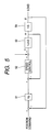
The control block diagram of Fig. 5 illustrates the
position control operation which is carried out by the
CPU 2 in Fig. 1. In Fig. 5, a position feedback supplied
from a load is subtracted from a position command. The
resultant value is multiplied by Kp to perform position
control. A difference between the value thus obtained
and a speed feedback ω is supplied to speed control 52
to output a torque command, thereby driving 1/JS53
corresponding to a motor and a load. Thereafter, a speed
feedback ω and the speed command are supplied to a
subtracter, thereby performing the speed control to remove
a speed deviation. The speed ω thus acquired is
integrated by integration 54, thus ending the position
control operation.
In the operation in this embodiment, the
microcomputer 2 in Fig. 1 receives a command of a position
or speed from an external controller. For example, in
the case of the speed command, the microcomputer 2 performs
the speed control operation. By the output current
command or an output of current control, the power
transistors 5 are driven through the base drive circuit
4 to control the motor 6. The vibration detecting member
1 detects the vibration when a vibration component
contained in a torque command or speed signal of the motor
exceeds a predetermined level. As a detection level of
vibration, the amplitude level of torque vibration during
the normal running or running peculiar to the machine
is detected as shown in Fig. 9. In Fig. 9, the maximum
value of the amplitude of torque vibration during the
normal running is detected.
The detection level of vibration may be e.g. about
three times as large as the vibration level during the
normal running.
For detection of the controlled gain, first,
simulated disturbance is added to a torque command at
a low gain to confirm a response. If there is no response,
the simulated disturbance torque is increased. The
simulated disturbance is increased until there is the
response increased to a certain degree, or otherwise the
level of response is lowered.
Next, the controlled gain is gradually increased
to add the simulated disturbance torque to the torque
command in Fig. 5, thereby confirming the vibration. The
confirmation that the vibration is stopped is obtained
from the amplitude of the speed and torque. If the
vibration is detected, the vibration is stopped by
lowering the controlled gain to the level where the
vibration does not occur or squeezing the torque. Finally,
the controlled gain providing the vibration is computed.
The controlled gain computed is determined as the maximum
gain.
The concrete procedure of gain adjustment is as
follows. First, in step 1 in Fig. 11, with the gain of
the control system such as a position loop or speed loop
being set at a low gain, as seen from Fig. 9, the vibration
level is detected during the normal running or during
the running peculiar to the machine. In Fig. 9, the
maximum value of the amplitude of torque vibration during
the normal running is detected.
In step 2 of Fig. 11, with the gain of the control
systembeing set at the low gain, the simulated disturbance
torque is added in steps to the torque command τref. In
step 3 of Fig. 11, whether or not the response of the
position deviation or speed exceeds a predetermined level
is confirmed. If there is not the response exceeding the
predetermined level, assuming that the simulated
disturbance torque added has not exceeded a mechanical
load, the simulated disturbance torque is increased. The
simulated disturbance torque is increased so that the
response is increased to a predetermined level. The level
of the response of the maximum value is may be e.g. twice
as large as the amplitude during the normal running. If
the simulated disturbance torque is increased to a certain
level, where the response is not increased, the detection
of response is lowered. In this way, the magnitude of
the simulated disturbance torque and the detection of
the response are adjusted.
After the magnitude of the simulated disturbance
torque is increased step by step at timings as shown in
Fig. 10. After the controlled gain has been increased
like steps 4 to 6 of Fig. 11, the simulated disturbance
torque is added to the torque command so that the vibration
is confirmed by the vibration detecting member 1 (Fig.
1). The vibration detecting member 1 compares the
amplitude of the torque or speed with a vibration detection
level and detects the amplitude when it is lager than
the detection level. The vibration detection level is
set at e.g. 1.5 times as large as the response level
previously adjusted.
After the simulated disturbance torque has been
added, in step 6 in Fig. 11, if the vibration exceeding
a certain level is detected, addition of the simulated
disturbance at the timings shown in Fig. 10 is stopped.
In step 7 in Fig. 11, the controlled gain is lowered to
the level where the vibration does not occur (half of
the vibration occurring level, low gain initially set,
etc.). Otherwise, in order to stop the vibration surely,
the torque command is squeezed or the location deviation
is made zero in a moment. In step 8 in Fig. 11, the
controlled gain just before that when the vibration occurs
and the control system are stored in the storage member
such as a microcomputer as the maximum gain. The
controlled gain thus stored is the maximum gain in this
control system. Next, in step 9 of Fig. 11, whether or
not all the control systems have been implemented is
determined. Where the control system to be implemented
still remains, in step 10 of Fig. 11, the control system
is changed to detect the maximum gain from step 4. In
step 9 of Fig. 11, if all the control systems have been
implemented, in step 11 of Fig. 11, the control system
with the controlled gain increased is selected as an
optimum control system.
The vibration detecting circuit 1 may be realized
by the microcomputer 2. Further, an integrating gain and
torque filter may be changed with the gain.
In accordance with the third embodiment, the
vibration is surely caused to occur using the simulated
disturbance torque suited to a machine, thereby acquiring
the maximum gain. In addition, immediately after the
vibration has occurred, it can be suppressed by decreasing
the gain so that it is not necessary to increase the gain
greatly. Thus, the danger due to occurrence of the
vibration can be prevented. Further, the optimum control
method can be automatically selected and adjusted.
Next, referring a sequence example of Fig. 13 and
a timing chart of Fig. 14, an explanation will be given
of the operation of the fourth embodiment in the circuit
of Fig. 12.
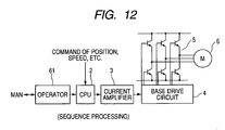
First, the CPU (microcomputer) 2 in Fig. 12
generally receives a command of a position or speed from
an external controller. For example, in the case of the
speed command, the microcomputer 2 performs the speed
control operation. By the output current command or an
output of current control, the power transistors 5 are
driven through the base drive circuit 4.
Now, for the purpose of an adjustment operation,
a man pulls out an operator 61 to carry out the adjustment
operation. In this case, the adjustment operation is
carried out according to e.g. a sequence of Fig. 13. The
sequence is implemented by the microcomputer 2.
In the sequence, first, the movable range as shown
in Fig. 4 is moved divisionally (Step 1). On the way,
the gain is increased (Step 2). The situation such as
the vibration is observed (Step 3). After the gain has
been determined, the movable range is fast moved (Step
4) to determine that the vibration has not occurred. If
the vibration occurs, the vibration is detected and the
gain is lowered (Step 3). Thereafter, at a normal speed,
positioning is confirmed (Step 5). This sequence may be
determined beforehand, or rearranged freely. The
command may be automatically created by the sequence or
externally supplied. In this way, a series of adjustment
operations will be carried out.
As understood from the above description, in
accordance with the fourth embodiment, a servo control
device for driving a servo motor is run by generating
a command by an external operation of an operator and
from a sequence of tuning build in the device, and the
gain is increased/decreased by the information obtained
at this time and hence determined in real time. Thus,
the gain can be instantaneously determined from the
vibration information. Even when the vibration occurs
because of differences in machines, the gain can be
instantaneously lowered and stopped.
This invention has been explained in detail
referring to various embodiments. It is apparent to those
skilled in the art that various changes and modifications
can be made without departing from the sprit and scope
of this invention.
[Industrial Applicability]
As described hitherto, in accordance with this
invention, by implementing the gain adjustment in such
a manner that the speed loop gain is increased to detect
vibration at each of points moved over a movable range
of a machine, the gain where the vibration becomes still
is detected as a maximum value of adjusted gains, and
a minimum value of these adjusted gains is adopted as
the entire adjusted gain, it is possible to realize
stabilized adjustment with a margin for the vibration,
thus suppressing changes according to the place of the
machine.
The above gain adjustment can be also applied to
the adjustment of the machine itself.
Further, by adjusting the controlled gain through
the normal running, occurrence of the vibration or noise
during stopping can be suppressed, thereby stabilizing
the controlled gain.
Further, the vibration is surely caused to occur
using the simulated disturbance torque suited to a machine,
thereby acquiring the maximum gain. In addition,
immediately after the vibration has occurred, it can be
suppressed by decreasing the gain so that it is not
necessary to increase the gain greatly. Thus, the danger
due to occurrence of the vibration can be prevented.
Further, the optimum control method can be automatically
selected and adjusted.
Further, since the sequence is built in by an external
operation, the gain can be detected in real time and also
by the information obtained at this time and hence can
be instantaneously determined from the vibration
information. Even when the vibration occurs because of
differences in machines, the gain can be instantaneously
lowered and stopped.