EP1536411A1 - Method and apparatus for continuous valued vocal tract resonance tracking using piecewise linear approximations - Google Patents
Method and apparatus for continuous valued vocal tract resonance tracking using piecewise linear approximations Download PDFInfo
- Publication number
- EP1536411A1 EP1536411A1 EP04025456A EP04025456A EP1536411A1 EP 1536411 A1 EP1536411 A1 EP 1536411A1 EP 04025456 A EP04025456 A EP 04025456A EP 04025456 A EP04025456 A EP 04025456A EP 1536411 A1 EP1536411 A1 EP 1536411A1
- Authority
- EP
- European Patent Office
- Prior art keywords
- linear
- vocal tract
- tract resonance
- vector
- function
- Prior art date
- Legal status (The legal status is an assumption and is not a legal conclusion. Google has not performed a legal analysis and makes no representation as to the accuracy of the status listed.)
- Granted
Links
- 230000001755 vocal effect Effects 0.000 title claims abstract description 68
- 238000000034 method Methods 0.000 title claims abstract description 26
- 239000013598 vector Substances 0.000 claims abstract description 111
- 238000012886 linear function Methods 0.000 claims abstract description 16
- 230000006870 function Effects 0.000 claims description 26
- 238000010586 diagram Methods 0.000 description 10
- 238000012549 training Methods 0.000 description 9
- 230000003595 spectral effect Effects 0.000 description 8
- 238000013139 quantization Methods 0.000 description 7
- 238000004891 communication Methods 0.000 description 6
- 239000011159 matrix material Substances 0.000 description 6
- 238000012545 processing Methods 0.000 description 6
- 230000003287 optical effect Effects 0.000 description 5
- 238000013507 mapping Methods 0.000 description 4
- 230000002093 peripheral effect Effects 0.000 description 4
- 230000006855 networking Effects 0.000 description 3
- 230000008569 process Effects 0.000 description 3
- 238000005070 sampling Methods 0.000 description 3
- 230000007704 transition Effects 0.000 description 3
- 239000000654 additive Substances 0.000 description 2
- 230000000996 additive effect Effects 0.000 description 2
- 230000001419 dependent effect Effects 0.000 description 2
- 238000005516 engineering process Methods 0.000 description 2
- 230000005055 memory storage Effects 0.000 description 2
- 238000013138 pruning Methods 0.000 description 2
- 239000007787 solid Substances 0.000 description 2
- 238000001228 spectrum Methods 0.000 description 2
- CDFKCKUONRRKJD-UHFFFAOYSA-N 1-(3-chlorophenoxy)-3-[2-[[3-(3-chlorophenoxy)-2-hydroxypropyl]amino]ethylamino]propan-2-ol;methanesulfonic acid Chemical compound CS(O)(=O)=O.CS(O)(=O)=O.C=1C=CC(Cl)=CC=1OCC(O)CNCCNCC(O)COC1=CC=CC(Cl)=C1 CDFKCKUONRRKJD-UHFFFAOYSA-N 0.000 description 1
- 238000004364 calculation method Methods 0.000 description 1
- 230000007246 mechanism Effects 0.000 description 1
- 238000000926 separation method Methods 0.000 description 1
- 238000012546 transfer Methods 0.000 description 1
- 230000007723 transport mechanism Effects 0.000 description 1
Images

Classifications
-
- G—PHYSICS
- G10—MUSICAL INSTRUMENTS; ACOUSTICS
- G10L—SPEECH ANALYSIS TECHNIQUES OR SPEECH SYNTHESIS; SPEECH RECOGNITION; SPEECH OR VOICE PROCESSING TECHNIQUES; SPEECH OR AUDIO CODING OR DECODING
- G10L25/00—Speech or voice analysis techniques not restricted to a single one of groups G10L15/00 - G10L21/00
- G10L25/48—Speech or voice analysis techniques not restricted to a single one of groups G10L15/00 - G10L21/00 specially adapted for particular use
-
- G—PHYSICS
- G10—MUSICAL INSTRUMENTS; ACOUSTICS
- G10L—SPEECH ANALYSIS TECHNIQUES OR SPEECH SYNTHESIS; SPEECH RECOGNITION; SPEECH OR VOICE PROCESSING TECHNIQUES; SPEECH OR AUDIO CODING OR DECODING
- G10L15/00—Speech recognition
- G10L15/02—Feature extraction for speech recognition; Selection of recognition unit
-
- G—PHYSICS
- G10—MUSICAL INSTRUMENTS; ACOUSTICS
- G10L—SPEECH ANALYSIS TECHNIQUES OR SPEECH SYNTHESIS; SPEECH RECOGNITION; SPEECH OR VOICE PROCESSING TECHNIQUES; SPEECH OR AUDIO CODING OR DECODING
- G10L25/00—Speech or voice analysis techniques not restricted to a single one of groups G10L15/00 - G10L21/00
- G10L25/03—Speech or voice analysis techniques not restricted to a single one of groups G10L15/00 - G10L21/00 characterised by the type of extracted parameters
- G10L25/15—Speech or voice analysis techniques not restricted to a single one of groups G10L15/00 - G10L21/00 characterised by the type of extracted parameters the extracted parameters being formant information
Definitions
- the present invention relates to speech recognition systems and in particular to speech recognition systems that exploit vocal tract resonances in speech.
- Such resonant frequencies and bandwidths are often referred to collectively as formants.
- formants can be found as spectral prominences in a frequency representation of the speech signal.
- the formants cannot be found directly as spectral prominences. Because of this, the term "formants” has sometimes been interpreted as only applying to sonorant portions of speech. To avoid confusion, some researchers use the phrase "vocal tract resonance" to refer to formants that occur during both sonorant and non-sonorant speech. In both cases, the resonance is related to only the oral tract portion of the vocal tract.
- LPC linear predictive coding
- the search space is reduced by comparing the spectral content of the frame to a set of spectral templates in which formants have been identified by an expert.
- the closest "n" templates are then selected and used to calculate the formants for the frame.
- these systems reduce the search space to those formants associated with the closest templates.
- One system of the prior art developed by the same inventors as the present invention, used a consistent search space that was the same for each frame of an input signal. Each set of formants in the search space was mapped into a feature vector. Each of the feature vectors was then applied to a model to determine which set of formants was most likely.
- This system works well but is computationally expensive because it typically utilizes Mel-Frequency Cepstral Coefficient frequency vectors, which require the application of a set of frequencies to a complex filter that is based on all of the formants in the set of formants that is being mapped followed by a windowing step and a discrete cosine transform step in order to map the formants into the feature vectors.
- This computation was too time-consuming to be performed at run time and thus all of the sets of formants had to be mapped before run time and the mapped feature vectors had to be stored in a large table. This is less than ideal because it requires a substantial amount of memory to store all of the mapped feature vectors.
- a set of discrete vocal tract resonance vectors are stored in a codebook.
- Each of the discrete vectors is converted into a simulated feature vector that is compared to an input feature vector to determine which discrete vector best represents an input speech signal.
- This system is less than ideal because it does not determine continuous values for the vocal tract resonance vectors but instead selects one of the discrete vocal tract resonance codewords.
- a method and apparatus tracks vocal tract resonance components in a speech signal.
- the components are tracked by defining a state equation that is linear with respect to a past vocal tract resonance vector and that predicts a current vocal tract resonance vector.
- An observation equation is also defined that is linear with respect to a current vocal tract resonance vector and that predicts at least one component of an observation vector.
- the state equation, the observation equation, and a sequence of observation vectors are used to identify a sequence of vocal tract resonance vectors.
- the observation equation is defined based on a linear approximation to a non-linear function.
- the parameters of the linear approximation are selected based on an estimate of a vocal tract resonance vector.
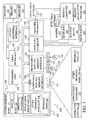
- FIG. 1 illustrates an example of a suitable computing system environment 100 on which the invention may be implemented.
- the computing system environment 100 is only one example of a suitable computing environment and is not intended to suggest any limitation as to the scope of use or functionality of the invention. Neither should the computing environment 100 be interpreted as having any dependency or requirement relating to any one or combination of components illustrated in the exemplary operating environment 100.
- the invention is operational with numerous other general purpose or special purpose computing system environments or configurations.
- Examples of well-known computing systems, environments, and/or configurations that may be suitable for use with the invention include, but are not limited to, personal computers, server computers, hand-held or laptop devices, multiprocessor systems, microprocessor-based systems, set top boxes, programmable consumer electronics, network PCs, minicomputers, mainframe computers, telephony systems, distributed computing environments that include any of the above systems or devices, and the like.
- the invention may be described in the general context of computer-executable instructions, such as program modules, being executed by a computer.
- program modules include routines, programs, objects, components, data structures, etc. that perform particular tasks or implement particular abstract data types.
- the invention is designed to be practiced in distributed computing environments where tasks are performed by remote processing devices that are linked through a communications network.
- program modules are located in both local and remote computer storage media including memory storage devices.
- an exemplary system for implementing the invention includes a general-purpose computing device in the form of a computer 110.
- Components of computer 110 may include, but are not limited to, a processing unit 120, a system memory 130, and a system bus 121 that couples various system components including the system memory to the processing unit 120.
- the system bus 121 may be any of several types of bus structures including a memory bus or memory controller, a peripheral bus, and a local bus using any of a variety of bus architectures.
- such architectures include Industry Standard Architecture (ISA) bus, Micro Channel Architecture (MCA) bus, Enhanced ISA (EISA) bus, Video Electronics Standards Association (VESA) local bus, and Peripheral Component Interconnect (PCI) bus also known as Mezzanine bus.
- ISA Industry Standard Architecture
- MCA Micro Channel Architecture
- EISA Enhanced ISA
- VESA Video Electronics Standards Association
- PCI Peripheral Component Interconnect
- Computer 110 typically includes a variety of computer readable media.
- Computer readable media can be any available media that can be accessed by computer 110 and includes both volatile and nonvolatile media, removable and non-removable media.
- Computer readable media may comprise computer storage media and communication media.
- Computer storage media includes both volatile and nonvolatile, removable and non-removable media implemented in any method or technology for storage of information such as computer readable instructions, data structures, program modules or other data.
- Computer storage media includes, but is not limited to, RAM, ROM, EEPROM, flash memory or other memory technology, CD-ROM, digital versatile disks (DVD) or other optical disk storage, magnetic cassettes, magnetic tape, magnetic disk storage or other magnetic storage devices, or any other medium which can be used to store the desired information and which can be accessed by computer 110.
- Communication media typically embodies computer readable instructions, data structures, program modules or other data in a modulated data signal such as a carrier wave or other transport mechanism and includes any information delivery media.
- modulated data signal means a signal that has one or more of its characteristics set or changed in such a manner as to encode information in the signal.
- communication media includes wired media such as a wired network or direct-wired connection, and wireless media such as acoustic, RF, infrared and other wireless media. Combinations of any of the above should also be included within the scope of computer readable media.
- the system memory 130 includes computer storage media in the form of volatile and/or nonvolatile memory such as read only memory (ROM) 131 and random access memory (RAM) 132.
- ROM read only memory
- RAM random access memory
- BIOS basic input/output system
- RAM 132 typically contains data and/or program modules that are immediately accessible to and/or presently being operated on by processing unit 120.
- FIG. 1 illustrates operating system 134, application programs 135, other program modules 136, and program data 137.
- the computer 110 may also include other removable/non-removable volatile/nonvolatile computer storage media.
- FIG. 1 illustrates a hard disk drive 141 that reads from or writes to non-removable, nonvolatile magnetic media, a magnetic disk drive 151 that reads from or writes to a removable, nonvolatile magnetic disk 152, and an optical disk drive 155 that reads from or writes to a removable, nonvolatile optical disk 156 such as a CD ROM or other optical media.
- removable/non-removable, volatile/nonvolatile computer storage media that can be used in the exemplary operating environment include, but are not limited to, magnetic tape cassettes, flash memory cards, digital versatile disks, digital video tape, solid state RAM, solid state ROM, and the like.
- the hard disk drive 141 is typically connected to the system bus 121 through a non-removable memory interface such as interface 140, and magnetic disk drive 151 and optical disk drive 155 are typically connected to the system bus 121 by a removable memory interface, such as interface 150.
- hard disk drive 141 is illustrated as storing operating system 144, application programs 145, other program modules 146, and program data 147. Note that these components can either be the same as or different from operating system 134, application programs 135, other program modules 136, and program data 137. Operating system 144, application programs 145, other program modules 146, and program data 147 are given different numbers here to illustrate that, at a minimum, they are different copies.
- a user may enter commands and information into the computer 110 through input devices such as a keyboard 162, a microphone 163, and a pointing device 161, such as a mouse, trackball or touch pad.
- Other input devices may include a joystick, game pad, satellite dish, scanner, or the like.
- a monitor 191 or other type of display device is also connected to the system bus 121 via an interface, such as a video interface 190.
- computers may also include other peripheral output devices such as speakers 197 and printer 196, which may be connected through an output peripheral interface 195.
- the computer 110 is operated in a networked environment using logical connections to one or more remote computers, such as a remote computer 180.
- the remote computer 180 may be a personal computer, a hand-held device, a server, a router, a network PC, a peer device or other common network node, and typically includes many or all of the elements described above relative to the computer 110.
- the logical connections depicted in FIG. 1 include a local area network (LAN) 171 and a wide area network (WAN) 173, but may also include other networks.
- LAN local area network
- WAN wide area network
- Such networking environments are commonplace in offices, enterprise-wide computer networks, intranets and the Internet.
- the computer 110 When used in a LAN networking environment, the computer 110 is connected to the LAN 171 through a network interface or adapter 170. When used in a WAN networking environment, the computer 110 typically includes a modem 172 or other means for establishing communications over the WAN 173, such as the Internet.
- the modem 172 which may be internal or external, may be connected to the system bus 121 via the user input interface 160, or other appropriate mechanism.
- program modules depicted relative to the computer 110, or portions thereof may be stored in the remote memory storage device.
- FIG. 1 illustrates remote application programs 185 as residing on remote computer 180. It will be appreciated that the network connections shown are exemplary and other means of establishing a communications link between the computers may be used.
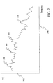
- FIG. 2 is a graph of the frequency spectrum of a section of human speech.
- frequency is shown along horizontal axis 200 and the magnitude of the frequency components is shown along vertical axis 202.
- the graph of FIG. 2 shows that sonorant human speech contains resonances or formants, such as first formant 204, second formant 206, third formant 208, and fourth formant 210.
- Each formant is described by its center frequency, F, and its bandwidth, B.
- the present invention provides methods for identifying the formant frequencies and bandwidths in a speech signal across a continuous range of formant frequencies and bandwidths, both in sonorant and non-sonorant speech.
- the invention is able to track vocal tract resonance frequencies and bandwidths.
- the present invention models the hidden vocal tract resonance frequencies and bandwidths as a sequence of hidden states that each produces an observation.
- x t -1 is a hidden vocal tract resonance vector at a previous time t-1
- ⁇ is a system matrix
- I is the identity matrix
- T is a target vector for the vocal tract resonance frequencies and bandwidths
- w t is noise in the state equation
- o t is an observed vector
- C ( x t ) is a mapping function from the hidden vocal tract resonance vector to an
- ⁇ is a diagonal matrix with each entry having a value between 0.7 and 0.9 that has been empirically determined
- T is a vector, which, in one embodiment, has a value of: (500 1500 2500 3500 200 300 400 400) T
- the noise parameters w t and v t have values determined by random Gaussian samples with a zero mean vector and with diagonal covariance matrices.
- the diagonal elements of these matrices in this embodiment have values between 10 and 30,000 for w t, and values between 0.8 and 78 for v t.
- the observed vector is a Linear Predictive Coding-Cepstra (LPC-cepstra) vector where each component of the vector represents an LPC order.
- LPC-cepstra Linear Predictive Coding-Cepstra
- the nth component of the vector-valued function C ( x t ) for frame t is: where C n ( x t ) is the nth element in an Nth order LPC-Cepstrum feature vector, K is the number of vocal tract resonance (VTR) frequencies, f k ( t ) is the k th VTR frequency for frame t, b k ( t ) is the kth VTR bandwidth for frame t, and f s is the sampling frequency, which in many embodiments is 8 kHz and in other embodiments is 16 kHz.
- the C 0 element is set equal to log G , where G is a gain.
- a Kalman filter provides a recursive technique that can determine a best estimate of the continuous-valued hidden vocal tract resonance vectors in the linear dynamic system represented by Equations 1 and 2.
- Such Kalman filters are well known in the art.
- Equation 3 The Kalman filter requires that the righthand side of Equations 1 and 2 be linear with respect to the hidden vocal tract resonance vector. However, the mapping function of Equation 3 is non-linear with respect to the vocal tract resonance vector. To address this, the present invention uses piecewise linear approximations in place of the exponent and cosine terms in Equation 3. Under one embodiment, the exponent term is represented by five linear regions and the cosine term is represented by ten linear regions.
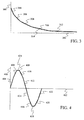
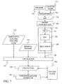
- FIG. 3 shows an example of a piecewise linear approximation to the exponent term in Equation 3.
- the value of the exponent is shown along vertical axis 300 and the value of bandwidth b k for the kth VTR bandwidth is shown along horizontal axis 302.
- five linear segments 304, 306, 308, 310 and 312 are used to approximate exponent graph 314.
- the following table provides ranges of exponent values that each of the linear segments cover.
- FIG. 4 shows an example of a piecewise linear approximation to the cosine term in Equation 3.
- the value of the cosine function is shown along vertical axis 400 and the value of frequency f k for the k th VTR frequency is shown along horizontal axis 402.
- a single cycle of the cosine function is shown, however, those skilled in the art will recognize that the same piecewise linear approximations can be used for each cycle of the cosine function.
- the cosine function 424 is approximated by ten linear segments 404, 406, 408, 410, 412, 414, 416, 418, 420 and 422.
- Equation 3 is rewritten as: where ⁇ kx is the slope and ⁇ kx is the intercept of the linear segment that approximates the exponent term and ⁇ kx is the slope and ⁇ kx is the intercept of the linear segment that approximates the cosine term. Note that all four terms are dependent on x t because the linear segments that are used to approximate the non-linear functions are selected based on the region determined by the value of x t according to Tables 1 and 2.
- Equation 4 The form of the mapping function in Equation 4 is still not linear in x t because of the quadratic term. Under one embodiment of the present invention, the incremental portion of this term is ignored, resulting in a linear equation from x t to C n ( x t ).
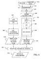
- FIG. 5 provides a general flow diagram of a method of selecting linear approximations and using the approximation in a Kalman Filter to identify a sequence of continuous valued states using Equations 1, 2 and 4 while ignoring the incremental portion of the quadratic term in Equation 4.
- FIGS. 6 and 7 provide block diagrams of components used in the method of FIG. 5.
- a vocal tract resonance (VTR) codebook stored in a table, is constructed by quantizing the possible VTR frequencies and bandwidths to form a set of quantized values and then forming entries for different combinations of the quantized values.
- VTR vocal tract resonance
- the ith entry x[i] in the codebook would be a vector of [F 1i , B 1i , F 2i , B 2i , F 3i , B 3i , F 4i , B 4i ] where F 1i , F 2i , F 3i , and F 4i are the frequencies of the first, second, third and fourth VTRs and B 1i , B 2i , B 3i , and B 4i are the bandwidths for the first, second, third and fourth VTRs.
- the index to the codebook, i is used interchangeably with the value stored at that index, x[i]. When the index is used alone below, it is intended to represent the value stored at that index.
- the formants and bandwidths are quantized according to the entries in Table 3 below, where Min(Hz) is the minimum value for the frequency or bandwidth in Hertz, Max(Hz) is the maximum value in Hertz, and "Num. Quant.” is the number of quantization states. For the frequencies and the bandwidths, the range between the minimum and maximum is divided by the number of quantization states to provide the separation between each of the quantization states. For example, for bandwidth B 1 in Table 3, the range of 260 Hz is evenly divided by the 5 quantization states such that each state is separated from the other states by 65 Hz. (i.e., 40, 105, 170, 235, 300). Min(Hz) Max(Hz) Num. Quant. F 1 200 900 20 F 2 600 2800 20 F 3 1400 3800 20 F 4 1700 5000 20 B 1 40 300 5 B 2 60 300 5 B 3 60 500 5 B 4 100 700 5
- the number of quantization states in Table 3 could yield a total of more than 100 million different sets of VTRs. However, because of the constraint F 1 ⁇ F 2 ⁇ F 3 ⁇ F 4 there are substantially fewer sets of VTRs in the codebook.
- the residual random variable is the difference between a set of observation training feature vectors and a set of simulated feature vectors.
- v t o t - S ( x t [ i ])
- v is the residual
- o is the observed training feature vector at time t
- S ( x t [ i ]) is a simulated feature vector.
- the simulated feature vectors S ( x t [ i ]) 610 are constructed when needed by applying a set of VTRs x t [ i ] in VTR codebook 600 to an LPC-Cepstrum calculator 602, which performs the following calculation: where S n ( x t [ i ]) is the nth element in an nth order LPC-Cepstrum feature vector, K is the number of VTRs, f k is the k th VTR frequency, b k is the kth VTR bandwidth, and f s is the sampling frequency, which in many embodiments is 8 kHz.
- the S 0 element is set equal to log G , where G is a gain.
- a human speaker 612 generates an acoustic signal that is detected by a microphone 616, which also detects additive noise 614.
- Microphone 616 converts the acoustic signals into an analog electrical signal that is provided to an analog-to-digital (A/D) converter 618.
- the analog signal is sampled by A/D converter 618 at the sampling frequency f s and the resulting samples are converted into digital values.
- A/D converter 618 samples the analog signal at 8 kHz with 16 bits per sample, thereby creating 16 kilobytes of speech data per second.
- A/D converter 68 samples the analog signal at 16kHz.
- the digital samples are provided to a frame constructor 620, which groups the samples into frames. Under one embodiment, frame constructor 620 creates a new frame every 10 milliseconds that includes 25 milliseconds worth of data.
- the frames of data are provided to an LPC-Cepstrum feature extractor 622, which converts the signal to the frequency domain using a Fast Fourier Transform (FFT) 624 and then identifies a polynomial that represents the spectral content of a frame of the speech signal using an LPC coefficient system 626.
- the LPC coefficients are converted into LPC cepstrum coefficients using a recursion 628.
- the output of the recursion is a set of training feature vectors 630 representing the training speech signal.
- the simulated feature vectors 610 and the training feature vectors 630 are provided to residual trainer 632 which trains the parameters for the residual v t .
- v t is a single Gaussian with mean h and a precision D , where h is a vector with a separate mean for each component of the feature vector and D is a diagonal precision matrix with a separate value for each component of the feature vector.
- EM Expectation-Maximization
- a posterior probability ⁇ t ( i ) p ( x t [ i ]
- o N / 1) is determined.
- this posterior is determined using a backward-forward recursion defined as: where ⁇ t ( i ) and ⁇ t ( i ) are recursively determined as:
- transition probabilities can be described as Gaussian functions: p ( x t [ i ]
- x t- 1 [ j ]) N ( x t [ i ]; ⁇ x t -1 [ i ] + (I - ⁇ )T, B ) p ( x t [ i ]
- x t +1 [ j ]) N ( x t +1 [ i ]; ⁇ x t [ i ] + (I - ⁇ )T, B )
- the posterior probability ⁇ t ( i ) p ( x t [ i ]
- o N / 1) may be estimated by making the probability only dependent on the current observation vector and not the sequence of vectors such that the posterior probability becomes: ⁇ t ( i ) ⁇ p ( x t [ i ]
- an M-step is performed to determine the mean h and each diagonal element d -1 of the variance D -1 (the inverse of the precision matrix) of the residual using: where N is the number of frames in the training utterance, I is the number of quantization combinations for the VTRs, o t is the observed feature vector at time t and S ( x t [ i ]) is a simulated feature vector for VTRs x t [ i ].
- Residual trainer 632 updates the mean and variance multiple times by iterating the E-step and the M-step, each time using the mean and variance from the previous iteration. After the mean and variance reach stable values, they are stored as residual parameters 634.
- FIG. 7 A block diagram of a system for identifying VTR vectors is shown in FIG. 7.
- a speech signal is generated by a speaker 712.
- the speech signal and additive noise 714 are converted into a stream of feature vectors 730 by a microphone 716, A/D converter 718, frame constructor 720, and feature extractor 722, which consists of an FFT 724, LPC system 726, and a recursion 728.
- microphone 716, A/D converter 718, frame constructor 720 and feature extractor 722 operate in a similar manner to microphone 616, A/D converter 618, frame constructor 620 and feature extractor 622 of FIG. 6.
- the stream of feature vectors 730 is provided to a VTR tracker 732 together with residual parameters 634 and simulated feature vectors 610.
- VTR tracker 732 uses dynamic programming to identify a sequence of most likely VTR vectors 734. In particular, it utilizes a Viterbi decoding algorithm where each node in the trellis diagram has an optimal partial score of: Based on the optimality principle, the optimal partial likelihood at the processing stage of t+1 can be computed using the following Viterbi recursion:
- Equation 18 The observation probability p ( o t +1
- x t +1 [ i ] x [ i ]) of Equation 18 is treated as a Gaussian and is computed from observation Equation 5 and the residual parameters h and D such that: p ( o t +1
- a pruning beam search may be performed instead of a rigorous Viterbi search.
- an extreme form of pruning is used where only one index is identified for each frame.
- initial VTR sequence 734 is provided to a linear parameter estimator 736, which selects the parameters for the linear approximations of Equation 4 above at step 506. Specifically, for each frame, the initial VTR vector for the frame is used to determine the values of the linear parameters ⁇ kx , ⁇ kx , ⁇ kx and ⁇ kx for each vocal tract resonance index k and each LPC order n.
- the values of linear parameters ⁇ kx and ⁇ kx are determined for an LPC order n by applying bandwidth b k of the initial VTR vector to the exponent term e - ⁇ n b k f s and evaluating the exponent.
- the linear segment of FIG. 3 that spans that value of the exponent is then selected, thereby selecting the linear parameters ⁇ kx and ⁇ kx that define the linear segment.
- each of these parameters is a vector that has a value of zero for every vector component except the vector component associated with bandwidth b k .
- the values of linear parameters ⁇ kx and ⁇ kx are determined for an LPC order n by applying frequency f k of the initial VTR vector to the cosine term cos(2 ⁇ n f k / f s ) and evaluating the cosine.
- the linear segment of FIG. 4 that spans that value of the cosine is then selected, thereby selecting the linear parameters ⁇ kx and ⁇ kx that define the linear segment.
- each of these parameters is a vector that has a value of zero for every vector component except the vector component associated with frequency f k .
- Equation 4 the linear parameters for each frame are applied to Equation 4. Ignoring the incremental portion of the quadratic term in Equation 4, equation 4 is used in Equation 2. Equations 1 and 2 are then provided to a Kalman filter 738, which re-estimates the VTR vectors 734 for each frame.
- the process determines if there are more iterations to be performed. If there are more iterations, the process returns to step 506, where the linear parameters are re-estimated from the new VTR vectors. The new linear parameters are then applied to Equation 2 through Equation 4 and Equations 1 and 2 are used in Kalman Filter 738 at step 508 to re-estimate the VTR vectors.
- Steps 506, 508 and 510 are iterated until a determination is made at step 510 that no further iterations are needed. At that point, the process ends at step 512 and the last estimation of VTR vectors 734 is used as the sequence of vocal tract resonance frequencies and bandwidths for the input signal.
- Kalman Filter 738 provides continuous values for the vocal tract resonance vectors.
- the resulting sequence of vocal tract resonance frequencies and bandwidths is not limited to the discrete values found in VTR codebook 600.
Landscapes
- Engineering & Computer Science (AREA)
- Physics & Mathematics (AREA)
- Multimedia (AREA)
- Health & Medical Sciences (AREA)
- Audiology, Speech & Language Pathology (AREA)
- Human Computer Interaction (AREA)
- Computational Linguistics (AREA)
- Acoustics & Sound (AREA)
- Signal Processing (AREA)
- Computer Vision & Pattern Recognition (AREA)
- Compression, Expansion, Code Conversion, And Decoders (AREA)
- Complex Calculations (AREA)
- Image Processing (AREA)
- Measuring Pulse, Heart Rate, Blood Pressure Or Blood Flow (AREA)
- Radar Systems Or Details Thereof (AREA)
Abstract
Description
- The present invention relates to speech recognition systems and in particular to speech recognition systems that exploit vocal tract resonances in speech.
- In human speech, a great deal of information is contained in the first three or four resonant frequencies of the speech signal. In particular, when a speaker is pronouncing a vowel, the frequencies (and to a less extent, bandwidths) of these resonances indicate which vowel is being spoken.
- Such resonant frequencies and bandwidths are often referred to collectively as formants. During sonorant speech, which is typically voiced, formants can be found as spectral prominences in a frequency representation of the speech signal. However, during non-sonorant speech, the formants cannot be found directly as spectral prominences. Because of this, the term "formants" has sometimes been interpreted as only applying to sonorant portions of speech. To avoid confusion, some researchers use the phrase "vocal tract resonance" to refer to formants that occur during both sonorant and non-sonorant speech. In both cases, the resonance is related to only the oral tract portion of the vocal tract.
- To detect formants, systems of the prior art analyzed the spectral content of a frame of the speech signal. Since a formant can be at any frequency, the prior art has attempted to limit the search space before identifying a most likely formant value. Under some systems of the prior art, the search space of possible formants is reduced by identifying peaks in the spectral content of the frame. Typically, this is done by using linear predictive coding (LPC) which attempts to find a polynomial that represents the spectral content of a frame of the speech signal. Each of the roots of this polynomial represents a possible resonant frequency in the signal and thus a possible formant. Thus, using LPC, the search space is reduced to those frequencies that form roots of the LPC polynomial.
- In other formant tracking systems of the prior art, the search space is reduced by comparing the spectral content of the frame to a set of spectral templates in which formants have been identified by an expert. The closest "n" templates are then selected and used to calculate the formants for the frame. Thus, these systems reduce the search space to those formants associated with the closest templates.
- One system of the prior art, developed by the same inventors as the present invention, used a consistent search space that was the same for each frame of an input signal. Each set of formants in the search space was mapped into a feature vector. Each of the feature vectors was then applied to a model to determine which set of formants was most likely.
- This system works well but is computationally expensive because it typically utilizes Mel-Frequency Cepstral Coefficient frequency vectors, which require the application of a set of frequencies to a complex filter that is based on all of the formants in the set of formants that is being mapped followed by a windowing step and a discrete cosine transform step in order to map the formants into the feature vectors. This computation was too time-consuming to be performed at run time and thus all of the sets of formants had to be mapped before run time and the mapped feature vectors had to be stored in a large table. This is less than ideal because it requires a substantial amount of memory to store all of the mapped feature vectors.
- In another system developed by the present inventors, a set of discrete vocal tract resonance vectors are stored in a codebook. Each of the discrete vectors is converted into a simulated feature vector that is compared to an input feature vector to determine which discrete vector best represents an input speech signal. This system is less than ideal because it does not determine continuous values for the vocal tract resonance vectors but instead selects one of the discrete vocal tract resonance codewords.
- A method and apparatus tracks vocal tract resonance components in a speech signal. The components are tracked by defining a state equation that is linear with respect to a past vocal tract resonance vector and that predicts a current vocal tract resonance vector. An observation equation is also defined that is linear with respect to a current vocal tract resonance vector and that predicts at least one component of an observation vector. The state equation, the observation equation, and a sequence of observation vectors are used to identify a sequence of vocal tract resonance vectors. Under one embodiment, the observation equation is defined based on a linear approximation to a non-linear function. The parameters of the linear approximation are selected based on an estimate of a vocal tract resonance vector.
-
- FIG. 1 is a block diagram of a general computing environment in which embodiments of the present invention may be practiced.
- FIG. 2 is a graph of the magnitude spectrum of a speech signal.
- FIG. 3 is a diagram showing a piecewise linear approximation to an exponential function.
- FIG. 4 is a diagram showing a piecewise linear approximation to a sinusoidal function.
- FIG. 5 is a flow diagram of a method under the present invention.
- FIG. 6 is a block diagram of a training system for training a residual model.
- FIG. 7 is a block diagram of a formant tracking system under one embodiment of the present invention.
-
- FIG. 1 illustrates an example of a suitable
computing system environment 100 on which the invention may be implemented. Thecomputing system environment 100 is only one example of a suitable computing environment and is not intended to suggest any limitation as to the scope of use or functionality of the invention. Neither should thecomputing environment 100 be interpreted as having any dependency or requirement relating to any one or combination of components illustrated in theexemplary operating environment 100. - The invention is operational with numerous other general purpose or special purpose computing system environments or configurations. Examples of well-known computing systems, environments, and/or configurations that may be suitable for use with the invention include, but are not limited to, personal computers, server computers, hand-held or laptop devices, multiprocessor systems, microprocessor-based systems, set top boxes, programmable consumer electronics, network PCs, minicomputers, mainframe computers, telephony systems, distributed computing environments that include any of the above systems or devices, and the like.
- The invention may be described in the general context of computer-executable instructions, such as program modules, being executed by a computer. Generally, program modules include routines, programs, objects, components, data structures, etc. that perform particular tasks or implement particular abstract data types. The invention is designed to be practiced in distributed computing environments where tasks are performed by remote processing devices that are linked through a communications network. In a distributed computing environment, program modules are located in both local and remote computer storage media including memory storage devices.
- With reference to FIG. 1, an exemplary system for implementing the invention includes a general-purpose computing device in the form of a
computer 110. Components ofcomputer 110 may include, but are not limited to, aprocessing unit 120, asystem memory 130, and asystem bus 121 that couples various system components including the system memory to theprocessing unit 120. Thesystem bus 121 may be any of several types of bus structures including a memory bus or memory controller, a peripheral bus, and a local bus using any of a variety of bus architectures. By way of example, and not limitation, such architectures include Industry Standard Architecture (ISA) bus, Micro Channel Architecture (MCA) bus, Enhanced ISA (EISA) bus, Video Electronics Standards Association (VESA) local bus, and Peripheral Component Interconnect (PCI) bus also known as Mezzanine bus. -
Computer 110 typically includes a variety of computer readable media. Computer readable media can be any available media that can be accessed bycomputer 110 and includes both volatile and nonvolatile media, removable and non-removable media. By way of example, and not limitation, computer readable media may comprise computer storage media and communication media. Computer storage media includes both volatile and nonvolatile, removable and non-removable media implemented in any method or technology for storage of information such as computer readable instructions, data structures, program modules or other data. Computer storage media includes, but is not limited to, RAM, ROM, EEPROM, flash memory or other memory technology, CD-ROM, digital versatile disks (DVD) or other optical disk storage, magnetic cassettes, magnetic tape, magnetic disk storage or other magnetic storage devices, or any other medium which can be used to store the desired information and which can be accessed bycomputer 110. Communication media typically embodies computer readable instructions, data structures, program modules or other data in a modulated data signal such as a carrier wave or other transport mechanism and includes any information delivery media. The term "modulated data signal" means a signal that has one or more of its characteristics set or changed in such a manner as to encode information in the signal. By way of example, and not limitation, communication media includes wired media such as a wired network or direct-wired connection, and wireless media such as acoustic, RF, infrared and other wireless media. Combinations of any of the above should also be included within the scope of computer readable media. - The
system memory 130 includes computer storage media in the form of volatile and/or nonvolatile memory such as read only memory (ROM) 131 and random access memory (RAM) 132. A basic input/output system 133 (BIOS), containing the basic routines that help to transfer information between elements withincomputer 110, such as during start-up, is typically stored inROM 131.RAM 132 typically contains data and/or program modules that are immediately accessible to and/or presently being operated on by processingunit 120. By way of example, and not limitation, FIG. 1 illustratesoperating system 134,application programs 135,other program modules 136, andprogram data 137. - The
computer 110 may also include other removable/non-removable volatile/nonvolatile computer storage media. By way of example only, FIG. 1 illustrates ahard disk drive 141 that reads from or writes to non-removable, nonvolatile magnetic media, amagnetic disk drive 151 that reads from or writes to a removable, nonvolatilemagnetic disk 152, and anoptical disk drive 155 that reads from or writes to a removable, nonvolatileoptical disk 156 such as a CD ROM or other optical media. Other removable/non-removable, volatile/nonvolatile computer storage media that can be used in the exemplary operating environment include, but are not limited to, magnetic tape cassettes, flash memory cards, digital versatile disks, digital video tape, solid state RAM, solid state ROM, and the like. Thehard disk drive 141 is typically connected to thesystem bus 121 through a non-removable memory interface such asinterface 140, andmagnetic disk drive 151 andoptical disk drive 155 are typically connected to thesystem bus 121 by a removable memory interface, such asinterface 150. - The drives and their associated computer storage media discussed above and illustrated in FIG. 1, provide storage of computer readable instructions, data structures, program modules and other data for the
computer 110. In FIG. 1, for example,hard disk drive 141 is illustrated as storingoperating system 144,application programs 145,other program modules 146, andprogram data 147. Note that these components can either be the same as or different fromoperating system 134,application programs 135,other program modules 136, andprogram data 137.Operating system 144,application programs 145,other program modules 146, andprogram data 147 are given different numbers here to illustrate that, at a minimum, they are different copies. - A user may enter commands and information into the
computer 110 through input devices such as akeyboard 162, amicrophone 163, and apointing device 161, such as a mouse, trackball or touch pad. Other input devices (not shown) may include a joystick, game pad, satellite dish, scanner, or the like. These and other input devices are often connected to theprocessing unit 120 through auser input interface 160 that is coupled to the system bus, but may be connected by other interface and bus structures, such as a parallel port, game port or a universal serial bus (USB). Amonitor 191 or other type of display device is also connected to thesystem bus 121 via an interface, such as avideo interface 190. In addition to the monitor, computers may also include other peripheral output devices such asspeakers 197 andprinter 196, which may be connected through an outputperipheral interface 195. - The
computer 110 is operated in a networked environment using logical connections to one or more remote computers, such as aremote computer 180. Theremote computer 180 may be a personal computer, a hand-held device, a server, a router, a network PC, a peer device or other common network node, and typically includes many or all of the elements described above relative to thecomputer 110. The logical connections depicted in FIG. 1 include a local area network (LAN) 171 and a wide area network (WAN) 173, but may also include other networks. Such networking environments are commonplace in offices, enterprise-wide computer networks, intranets and the Internet. - When used in a LAN networking environment, the
computer 110 is connected to theLAN 171 through a network interface oradapter 170. When used in a WAN networking environment, thecomputer 110 typically includes amodem 172 or other means for establishing communications over theWAN 173, such as the Internet. Themodem 172, which may be internal or external, may be connected to thesystem bus 121 via theuser input interface 160, or other appropriate mechanism. In a networked environment, program modules depicted relative to thecomputer 110, or portions thereof, may be stored in the remote memory storage device. By way of example, and not limitation, FIG. 1 illustratesremote application programs 185 as residing onremote computer 180. It will be appreciated that the network connections shown are exemplary and other means of establishing a communications link between the computers may be used. - FIG. 2 is a graph of the frequency spectrum of a section of human speech. In FIG. 2, frequency is shown along
horizontal axis 200 and the magnitude of the frequency components is shown alongvertical axis 202. The graph of FIG. 2 shows that sonorant human speech contains resonances or formants, such asfirst formant 204,second formant 206,third formant 208, andfourth formant 210. Each formant is described by its center frequency, F, and its bandwidth, B. - The present invention provides methods for identifying the formant frequencies and bandwidths in a speech signal across a continuous range of formant frequencies and bandwidths, both in sonorant and non-sonorant speech. Thus, the invention is able to track vocal tract resonance frequencies and bandwidths.
- To do this, the present invention models the hidden vocal tract resonance frequencies and bandwidths as a sequence of hidden states that each produces an observation. In one particular embodiment, the hidden vocal tract resonance frequencies and bandwidths are modeled using a state equation of:
(500 1500 2500 3500 200 300 400 400)T
Under this embodiment, the noise parameters w t and v t have values determined by random Gaussian samples with a zero mean vector and with diagonal covariance matrices. The diagonal elements of these matrices in this embodiment have values between 10 and 30,000 for wt, and values between 0.8 and 78 for vt. - Under one embodiment, the observed vector is a Linear Predictive Coding-Cepstra (LPC-cepstra) vector where each component of the vector represents an LPC order. As a result, the mapping function C(x t ) can be determined precisely by an analytical nonlinear function. The nth component of the vector-valued function C(x t ) for frame t is:where Cn (x t ) is the nth element in an Nth order LPC-Cepstrum feature vector, K is the number of vocal tract resonance (VTR) frequencies, fk (t) is the kth VTR frequency for frame t, bk (t) is the kth VTR bandwidth for frame t, and fs is the sampling frequency, which in many embodiments is 8 kHz and in other embodiments is 16 kHz. The C 0 element is set equal to logG, where G is a gain.

- To identify a sequence of hidden vocal tract resonance vectors from a sequence of observation vectors, the present invention uses a Kalman filter. A Kalman filter provides a recursive technique that can determine a best estimate of the continuous-valued hidden vocal tract resonance vectors in the linear dynamic system represented by Equations 1 and 2. Such Kalman filters are well known in the art.
- The Kalman filter requires that the righthand side of Equations 1 and 2 be linear with respect to the hidden vocal tract resonance vector. However, the mapping function of
Equation 3 is non-linear with respect to the vocal tract resonance vector. To address this, the present invention uses piecewise linear approximations in place of the exponent and cosine terms inEquation 3. Under one embodiment, the exponent term is represented by five linear regions and the cosine term is represented by ten linear regions. - FIG. 3 shows an example of a piecewise linear approximation to the exponent term in
Equation 3. The value of the exponent is shown alongvertical axis 300 and the value of bandwidth bk for the kth VTR bandwidth is shown alonghorizontal axis 302. In FIG. 3, fivelinear segments approximate exponent graph 314. The following table provides ranges of exponent values that each of the linear segments cover.Linear Segment Range Of Exponent Values 304 0 - 100 Hz 306 100 - 200 Hz 308 200 - 300 Hz 310 300 - 400 Hz 312 400 - 500 Hz - FIG. 4 shows an example of a piecewise linear approximation to the cosine term in
Equation 3. The value of the cosine function is shown alongvertical axis 400 and the value of frequency fk for the kth VTR frequency is shown alonghorizontal axis 402. In FIG. 4, a single cycle of the cosine function is shown, however, those skilled in the art will recognize that the same piecewise linear approximations can be used for each cycle of the cosine function. Under the embodiment of FIG. 4, thecosine function 424 is approximated by tenlinear segments Linear Segment Range of Cosine Values 404 0 - 500 Hz 406 500 - 1000 Hz 408 1000 - 3000 Hz 410 3000 - 3500 Hz 412 3500 - 4000 Hz 414 4000 - 4500 Hz 416 4500 - 5000 Hz 418 5000 - 7000 Hz 420 7000 - 7500 Hz 422 7500 - 8000 Hz - Using these linear approximations,
Equation 3 is rewritten as:where α kx is the slope and β kx is the intercept of the linear segment that approximates the exponent term and γ kx is the slope and δ kx is the intercept of the linear segment that approximates the cosine term. Note that all four terms are dependent on x t because the linear segments that are used to approximate the non-linear functions are selected based on the region determined by the value of x t according to Tables 1 and 2.
- The form of the mapping function in Equation 4 is still not linear in x t because of the quadratic term. Under one embodiment of the present invention, the incremental portion of this term is ignored, resulting in a linear equation from x t to Cn ( x t ).
- In this form, as long as the parameters are fixed based on the regions of the segment exemplified in Tables 1 and 2, a Kalman Filter is applied directly to obtain the sequence of continuous valued states x 1: T from a sequence of observed LPC feature vectors o 1: T .
- FIG. 5 provides a general flow diagram of a method of selecting linear approximations and using the approximation in a Kalman Filter to identify a sequence of continuous valued states using Equations 1, 2 and 4 while ignoring the incremental portion of the quadratic term in Equation 4. FIGS. 6 and 7 provide block diagrams of components used in the method of FIG. 5.
- In
step 500 of FIG. 5, a vocal tract resonance (VTR) codebook, stored in a table, is constructed by quantizing the possible VTR frequencies and bandwidths to form a set of quantized values and then forming entries for different combinations of the quantized values. Thus, the resulting codebook contains entries that are vectors of VTR frequencies and bandwidths. For example, if the codebook contains entries for four VTRs, the ith entry x[i] in the codebook would be a vector of [F1i, B1i, F2i, B2i, F3i, B3i, F4i, B4i] where F1i, F2i, F3i, and F4i are the frequencies of the first, second, third and fourth VTRs and B1i, B2i, B3i, and B4i are the bandwidths for the first, second, third and fourth VTRs. In the discussion below, the index to the codebook, i, is used interchangeably with the value stored at that index, x[i]. When the index is used alone below, it is intended to represent the value stored at that index. - Under one embodiment, the formants and bandwidths are quantized according to the entries in Table 3 below, where Min(Hz) is the minimum value for the frequency or bandwidth in Hertz, Max(Hz) is the maximum value in Hertz, and "Num. Quant." is the number of quantization states. For the frequencies and the bandwidths, the range between the minimum and maximum is divided by the number of quantization states to provide the separation between each of the quantization states. For example, for bandwidth B1 in Table 3, the range of 260 Hz is evenly divided by the 5 quantization states such that each state is separated from the other states by 65 Hz. (i.e., 40, 105, 170, 235, 300).
Min(Hz) Max(Hz) Num. Quant. F 1200 900 20 F 2600 2800 20 F3 1400 3800 20 F4 1700 5000 20 B1 40 300 5 B2 60 300 5 B3 60 500 5 B 4100 700 5 - The number of quantization states in Table 3 could yield a total of more than 100 million different sets of VTRs. However, because of the constraint F1<F2<F3<F4 there are substantially fewer sets of VTRs in the codebook.
- After the codebook has been formed, the entries in the codebook are used to train parameters that describe a residual random variable at
step 502. The residual random variable is the difference between a set of observation training feature vectors and a set of simulated feature vectors. In terms of an equation: - As shown in FIG. 6, the simulated feature vectors S(xt [i]) 610 are constructed when needed by applying a set of VTRs xt [i] in
VTR codebook 600 to an LPC-Cepstrum calculator 602, which performs the following calculation:where Sn (xt [i]) is the nth element in an nth order LPC-Cepstrum feature vector, K is the number of VTRs, fk is the kth VTR frequency, bk is the kth VTR bandwidth, and fs is the sampling frequency, which in many embodiments is 8 kHz. The S 0 element is set equal to logG, where G is a gain.
- To produce the observed training feature vectors o t used to train the residual model, a
human speaker 612 generates an acoustic signal that is detected by amicrophone 616, which also detectsadditive noise 614.Microphone 616 converts the acoustic signals into an analog electrical signal that is provided to an analog-to-digital (A/D)converter 618. The analog signal is sampled by A/D converter 618 at the sampling frequency fs and the resulting samples are converted into digital values. In one embodiment, A/D converter 618 samples the analog signal at 8 kHz with 16 bits per sample, thereby creating 16 kilobytes of speech data per second. In other embodiments, A/D converter 68 samples the analog signal at 16kHz. The digital samples are provided to aframe constructor 620, which groups the samples into frames. Under one embodiment,frame constructor 620 creates a new frame every 10 milliseconds that includes 25 milliseconds worth of data. - The frames of data are provided to an LPC-
Cepstrum feature extractor 622, which converts the signal to the frequency domain using a Fast Fourier Transform (FFT) 624 and then identifies a polynomial that represents the spectral content of a frame of the speech signal using anLPC coefficient system 626. The LPC coefficients are converted into LPC cepstrum coefficients using arecursion 628. The output of the recursion is a set oftraining feature vectors 630 representing the training speech signal. - The
simulated feature vectors 610 and thetraining feature vectors 630 are provided toresidual trainer 632 which trains the parameters for the residual v t . - Under one embodiment, v t is a single Gaussian with mean h and a precision D, where h is a vector with a separate mean for each component of the feature vector and D is a diagonal precision matrix with a separate value for each component of the feature vector.
- These parameters are trained using an Expectation-Maximization (EM) algorithm under one embodiment of the present invention. During the E-step of this algorithm, a posterior probability γ t (i)=p(xt [i]|o N / 1) is determined. Under one embodiment, this posterior is determined using a backward-forward recursion defined as:where ρ t (i) and σ t (i) are recursively determined as:



- Under one aspect of the invention, the transition probabilities p(xt [i]|xt -1[j]) and p(xt [i]|xt +1[j]) are determined using Equation 1 above, which is repeated here for convenience using the codebook index notation:
- Using this dynamic model, the transition probabilities can be described as Gaussian functions:
- Alternatively, the posterior probability γ t (i)=p(xt [i]|o N / 1) may be estimated by making the probability only dependent on the current observation vector and not the sequence of vectors such that the posterior probability becomes:where h and is the mean of the residual and D and is the precision of the residual as determined from a previous iteration of the EM algorithm or as initially set if this is the first iteration.

- After the E-step is performed to identify the posterior probability γ t (i)=p(xt [i]|o N / 1), an M-step is performed to determine the mean h and each diagonal element d -1 of the variance D -1 (the inverse of the precision matrix) of the residual using:
 where N is the number of frames in the training utterance, I is the number of quantization combinations for the VTRs, ot is the observed feature vector at time t and S(xt [i]) is a simulated feature vector for VTRs xt [i].
-
Residual trainer 632 updates the mean and variance multiple times by iterating the E-step and the M-step, each time using the mean and variance from the previous iteration. After the mean and variance reach stable values, they are stored asresidual parameters 634. - Once
residual parameters 634 have been constructed they can be used instep 504 of FIG. 5 to identify VTR vectors in an input speech signal. A block diagram of a system for identifying VTR vectors is shown in FIG. 7. - In FIG. 7, a speech signal is generated by a
speaker 712. The speech signal andadditive noise 714 are converted into a stream offeature vectors 730 by amicrophone 716, A/D converter 718, frame constructor 720, andfeature extractor 722, which consists of anFFT 724,LPC system 726, and arecursion 728. Note thatmicrophone 716, A/D converter 718, frame constructor 720 andfeature extractor 722 operate in a similar manner tomicrophone 616, A/D converter 618,frame constructor 620 andfeature extractor 622 of FIG. 6. - The stream of
feature vectors 730 is provided to aVTR tracker 732 together withresidual parameters 634 andsimulated feature vectors 610.VTR tracker 732 uses dynamic programming to identify a sequence of mostlikely VTR vectors 734. In particular, it utilizes a Viterbi decoding algorithm where each node in the trellis diagram has an optimal partial score of:Based on the optimality principle, the optimal partial likelihood at the processing stage of t+1 can be computed using the following Viterbi recursion: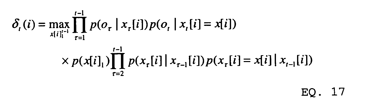

- In Equation 18, the "transition" probability p(xt +1[i]=x[i]|xt [i]=x[i']) is calculated using state Equation 10 above to produce a Gaussian distribution of:
- The observation probability p(ot +1|xt +1[i]=x[i]) of Equation 18 is treated as a Gaussian and is computed from
observation Equation 5 and the residual parameters h and D such that:initial VTR sequence 734. - To reduce the number of computations that must be performed, a pruning beam search may be performed instead of a rigorous Viterbi search. In one embodiment, an extreme form of pruning is used where only one index is identified for each frame.
- After
initial VTR sequence 734 has been identified atstep 504, the initial VTR sequence is provided to alinear parameter estimator 736, which selects the parameters for the linear approximations of Equation 4 above atstep 506. Specifically, for each frame, the initial VTR vector for the frame is used to determine the values of the linear parameters α kx , β kx , γ kx and δ kx for each vocal tract resonance index k and each LPC order n. - Under one embodiment, the values of linear parameters α kx and β kx are determined for an LPC order n by applying bandwidth bk of the initial VTR vector to the exponent term
- Under one embodiment, the values of linear parameters γ kx and δ kx are determined for an LPC order n by applying frequency fk of the initial VTR vector to the cosine term cos(2πn fk / fs ) and evaluating the cosine. The linear segment of FIG. 4 that spans that value of the cosine is then selected, thereby selecting the linear parameters γ kx and δ kx that define the linear segment. Note that each of these parameters is a vector that has a value of zero for every vector component except the vector component associated with frequency fk .
- At
step 508, the linear parameters for each frame are applied to Equation 4. Ignoring the incremental portion of the quadratic term in Equation 4, equation 4 is used in Equation 2. Equations 1 and 2 are then provided to aKalman filter 738, which re-estimates theVTR vectors 734 for each frame. Atstep 510, the process determines if there are more iterations to be performed. If there are more iterations, the process returns to step 506, where the linear parameters are re-estimated from the new VTR vectors. The new linear parameters are then applied to Equation 2 through Equation 4 and Equations 1 and 2 are used inKalman Filter 738 atstep 508 to re-estimate the VTR vectors.Steps step 510 that no further iterations are needed. At that point, the process ends atstep 512 and the last estimation ofVTR vectors 734 is used as the sequence of vocal tract resonance frequencies and bandwidths for the input signal. - Note that the
Kalman Filter 738 provides continuous values for the vocal tract resonance vectors. Thus, the resulting sequence of vocal tract resonance frequencies and bandwidths is not limited to the discrete values found inVTR codebook 600. - Although the present invention has been described with reference to particular embodiments, workers skilled in the art will recognize that changes may be made in form and detail without departing from the spirit and scope of the invention.
Claims (22)
- A method of tracking vocal tract resonance frequency in a speech signal, the method comprising:defining a state equation that is linear with respect to a past vocal tract resonance vector and that predicts a current vocal tract resonance vector;defining an observation equation that is linear with respect to a current vocal tract resonance vector and that predicts at least one component of an observation vector; andusing the state equation, the observation equation, and a sequence of observation vectors to identify a sequence of vocal tract resonance vectors, each vocal tract resonance vector comprising at least one vocal tract resonance frequency.
- The method of claim 1 wherein using the state equation, the observation equation, and the sequence of observation vectors to identify a sequence of vocal tract resonance vectors comprises applying the state equation, the observation equation and the sequence of observation vectors to a Kalman Filter.
- The method of claim 1 wherein identifying a vocal tract resonance vector comprises identifying a vocal tract resonance vector from a continuous set of values.
- The method of claim 1 wherein defining the observation equation comprises defining a linear approximation to a function that is non-linear with respect to the vocal tract resonance vector.
- The method of claim 4 wherein defining the observation equation further comprises defining a linear approximation to the product of two functions that are each non-linear with respect to the vocal tract resonance vector.
- The method of claim 5 wherein one of the functions that is non-linear with respect to the vocal tract resonance vector is an exponential function that is non-linear with respect to the bandwidth components of the vocal tract resonance vector.
- The method of claim 5 wherein one of the functions that is non-linear with respect to the vocal tract resonance vector is a sinusoidal function that is non-linear with respect to the frequency components of the vocal tract resonance vector.
- The method of claim 4 wherein defining a linear approximation comprises selecting a linear approximation from a set of linear approximations that together form a piecewise linear approximation to the non-linear function.
- The method of claim 4 wherein defining a linear approximation comprises evaluating the non-linear function based on an estimate of a vocal tract resonance vector to produce a non-linear function value and using the non-linear function value to select parameters for the linear approximation.
- The method of claim 9 wherein defining a linear approximation further comprises using the non-linear function value to select a linear approximation from a set of linear approximations that together form a piecewise linear approximation to the non-linear function.
- The method of claim 1 further comprising:using the identified vocal tract resonance vectors to redefine the observation equation; andusing the redefined observation equation, the state equation, and the observation vectors to identify a new sequence of vocal tract resonance vectors.
- The method of claim 11 wherein redefining the observation equation comprises using an identified vocal tract resonance vector to select parameters for at least one linear approximation to a function that is non-linear with respect to a vocal tract resonance vector.
- The method of claim 12 wherein using an identified vocal tract resonance vector to select parameters comprises evaluating the non-linear function using the vocal tract resonance vector to produce a non-linear function value and using the non-linear function value to select parameters for at least one linear approximation.
- A computer-readable medium having computer-executable instructions for performing steps comprising:using an estimate of at least one vocal tract resonance component to select a linear approximation to a function that is non-linear with respect to the vocal tract resonance component;using the linear approximation to define an observation equation; andusing the observation equation and at least one observed vector to re-estimate the vocal tract resonance component.
- The computer-readable medium of claim 14 wherein selecting a linear approximation comprises selecting one linear approximation from a set of linear approximations that form a piecewise linear approximation of the non-linear function.
- The computer-readable medium of claim 14 wherein selecting a linear approximation comprises applying the vocal tract resonance component to the non-linear function to form a function value and selecting the linear approximation based on the function value.
- The computer-readable medium of claim 14 wherein re-estimating the value of the vocal tract resonance component further comprises using a state equation that is linear with respect to the vocal tract resonance component.
- The computer-readable medium of claim 17 wherein re-estimating the value of the vocal tract resonance component further comprises applying the state equation, the observation equation and the at least one observed vector to a Kalman Filter.
- The computer-readable medium of claim 14 further comprising selecting a second linear approximation to a second function that is non-linear with respect to the vocal tract resonance component and using the second linear approximation to define the observation equation.
- The computer-readable medium of claim 14 wherein the non-linear function comprises an exponential function.
- The computer-readable medium of claim 14 wherein the non-linear function comprises a sinusoidal function.
- The computer-readable medium of claim 14 wherein the vocal tract resonance component is continuous valued.
Applications Claiming Priority (2)
| Application Number | Priority Date | Filing Date | Title |
|---|---|---|---|
| US723995 | 2003-11-26 | ||
| US10/723,995 US20050114134A1 (en) | 2003-11-26 | 2003-11-26 | Method and apparatus for continuous valued vocal tract resonance tracking using piecewise linear approximations |
Publications (2)
| Publication Number | Publication Date |
|---|---|
| EP1536411A1 true EP1536411A1 (en) | 2005-06-01 |
| EP1536411B1 EP1536411B1 (en) | 2007-06-27 |
Family
ID=34465720
Family Applications (1)
| Application Number | Title | Priority Date | Filing Date |
|---|---|---|---|
| EP04025456A Expired - Lifetime EP1536411B1 (en) | 2003-11-26 | 2004-10-26 | Method for continuous valued vocal tract resonance tracking using piecewise linear approximations |
Country Status (7)
| Country | Link |
|---|---|
| US (1) | US20050114134A1 (en) |
| EP (1) | EP1536411B1 (en) |
| JP (1) | JP2005157350A (en) |
| KR (1) | KR20050050533A (en) |
| CN (1) | CN1624765A (en) |
| AT (1) | ATE365960T1 (en) |
| DE (1) | DE602004007223T2 (en) |
Families Citing this family (8)
| Publication number | Priority date | Publication date | Assignee | Title |
|---|---|---|---|---|
| US20040199383A1 (en) * | 2001-11-16 | 2004-10-07 | Yumiko Kato | Speech encoder, speech decoder, speech endoding method, and speech decoding method |
| US7079342B1 (en) * | 2004-07-26 | 2006-07-18 | Marvell International Ltd. | Method and apparatus for asymmetry correction in magnetic recording channels |
| US7653535B2 (en) * | 2005-12-15 | 2010-01-26 | Microsoft Corporation | Learning statistically characterized resonance targets in a hidden trajectory model |
| CN101281744B (en) * | 2007-04-04 | 2011-07-06 | 纽昂斯通讯公司 | Method and apparatus for analyzing and synthesizing voice |
| US8164845B1 (en) | 2007-08-08 | 2012-04-24 | Marvell International Ltd. | Method and apparatus for asymmetry correction in magnetic recording channels |
| US20100145687A1 (en) * | 2008-12-04 | 2010-06-10 | Microsoft Corporation | Removing noise from speech |
| CN101693371B (en) * | 2009-09-30 | 2011-08-24 | 深圳先进技术研究院 | Robot capable of dancing by following music beats |
| US10466967B2 (en) | 2016-07-29 | 2019-11-05 | Qualcomm Incorporated | System and method for piecewise linear approximation |
Citations (1)
| Publication number | Priority date | Publication date | Assignee | Title |
|---|---|---|---|---|
| US6505152B1 (en) * | 1999-09-03 | 2003-01-07 | Microsoft Corporation | Method and apparatus for using formant models in speech systems |
Family Cites Families (8)
| Publication number | Priority date | Publication date | Assignee | Title |
|---|---|---|---|---|
| US4790016A (en) * | 1985-11-14 | 1988-12-06 | Gte Laboratories Incorporated | Adaptive method and apparatus for coding speech |
| JP2600871B2 (en) * | 1987-12-16 | 1997-04-16 | 松下電器産業株式会社 | HMM creation device, likelihood calculation device and time-series pattern recognition device using the same |
| JP2969862B2 (en) * | 1989-10-04 | 1999-11-02 | 松下電器産業株式会社 | Voice recognition device |
| US5148488A (en) * | 1989-11-17 | 1992-09-15 | Nynex Corporation | Method and filter for enhancing a noisy speech signal |
| JPH03181999A (en) * | 1989-12-12 | 1991-08-07 | Matsushita Electric Ind Co Ltd | HMM device |
| DE69533259T2 (en) * | 1995-05-03 | 2005-08-18 | Sony Corp. | NONLINEAR QUANTIZATION OF AN INFORMATION SIGNAL |
| JPH10111862A (en) * | 1996-08-13 | 1998-04-28 | Fujitsu Ltd | Time series analysis apparatus and method based on recursive neural network |
| US6567777B1 (en) * | 2000-08-02 | 2003-05-20 | Motorola, Inc. | Efficient magnitude spectrum approximation |
-
2003
- 2003-11-26 US US10/723,995 patent/US20050114134A1/en not_active Abandoned
-
2004
- 2004-10-26 AT AT04025456T patent/ATE365960T1/en not_active IP Right Cessation
- 2004-10-26 DE DE602004007223T patent/DE602004007223T2/en not_active Expired - Lifetime
- 2004-10-26 EP EP04025456A patent/EP1536411B1/en not_active Expired - Lifetime
- 2004-11-03 KR KR1020040088819A patent/KR20050050533A/en not_active Withdrawn
- 2004-11-12 JP JP2004329652A patent/JP2005157350A/en active Pending
- 2004-11-26 CN CNA2004100956562A patent/CN1624765A/en active Pending
Patent Citations (1)
| Publication number | Priority date | Publication date | Assignee | Title |
|---|---|---|---|---|
| US6505152B1 (en) * | 1999-09-03 | 2003-01-07 | Microsoft Corporation | Method and apparatus for using formant models in speech systems |
Non-Patent Citations (3)
| Title |
|---|
| DENG L ET AL: "Tracking vocal tract resonances using an analytical nonlinear predictor and a target-guided temporal constraint", PROC. OF EUROSPEECH 2003, September 2003 (2003-09-01), pages 73 - 76, XP002305040 * |
| LI DENG ET AL: "A structured speech model with continuous hidden dynamics and prediction-residual training for tracking vocal tract resonances", 2004 IEEE INTERNATIONAL CONFERENCE ON ACOUSTICS, SPEECH, AND SIGNAL PROCESSING IEEE PISCATAWAY, NJ, USA, vol. 1, 17 May 2004 (2004-05-17), pages 557 - 560, XP002306580, ISBN: 0-7803-8484-9 * |
| RIGOLL G: "Formant tracking with quasilinearization", 1988 INTERNATIONAL CONFERENCE ON ACOUSTICS, SPEECH, AND SIGNAL PROCESSING ICASSP, 11 April 1988 (1988-04-11), pages 306 - 310, XP010072810 * |
Also Published As
| Publication number | Publication date |
|---|---|
| CN1624765A (en) | 2005-06-08 |
| JP2005157350A (en) | 2005-06-16 |
| EP1536411B1 (en) | 2007-06-27 |
| DE602004007223D1 (en) | 2007-08-09 |
| ATE365960T1 (en) | 2007-07-15 |
| KR20050050533A (en) | 2005-05-31 |
| US20050114134A1 (en) | 2005-05-26 |
| DE602004007223T2 (en) | 2007-10-11 |
Similar Documents
| Publication | Publication Date | Title |
|---|---|---|
| US5590242A (en) | Signal bias removal for robust telephone speech recognition | |
| US7139703B2 (en) | Method of iterative noise estimation in a recursive framework | |
| US9640186B2 (en) | Deep scattering spectrum in acoustic modeling for speech recognition | |
| US7925502B2 (en) | Pitch model for noise estimation | |
| EP1693826B1 (en) | Vocal tract resonance tracking using a nonlinear predictor | |
| EP1465153B1 (en) | Method and apparatus for formant tracking using a residual model | |
| US6944590B2 (en) | Method of iterative noise estimation in a recursive framework | |
| US7617104B2 (en) | Method of speech recognition using hidden trajectory Hidden Markov Models | |
| Bacchiani et al. | Joint lexicon, acoustic unit inventory and model design | |
| Deng et al. | Adaptive Kalman filtering and smoothing for tracking vocal tract resonances using a continuous-valued hidden dynamic model | |
| EP1536411B1 (en) | Method for continuous valued vocal tract resonance tracking using piecewise linear approximations | |
| US7409346B2 (en) | Two-stage implementation for phonetic recognition using a bi-directional target-filtering model of speech coarticulation and reduction | |
| KR100897555B1 (en) | Speech feature vector extraction apparatus and method and speech recognition system and method employing same | |
| US7565284B2 (en) | Acoustic models with structured hidden dynamics with integration over many possible hidden trajectories | |
| US7475011B2 (en) | Greedy algorithm for identifying values for vocal tract resonance vectors | |
| D'haes et al. | Discrete cepstrum coefficients as perceptual features |
Legal Events
| Date | Code | Title | Description |
|---|---|---|---|
| PUAI | Public reference made under article 153(3) epc to a published international application that has entered the european phase |
Free format text: ORIGINAL CODE: 0009012 |
|
| AK | Designated contracting states |
Kind code of ref document: A1 Designated state(s): AT BE BG CH CY CZ DE DK EE ES FI FR GB GR HU IE IT LI LU MC NL PL PT RO SE SI SK TR |
|
| AX | Request for extension of the european patent |
Extension state: AL HR LT LV MK |
|
| 17P | Request for examination filed |
Effective date: 20051027 |
|
| AKX | Designation fees paid |
Designated state(s): AT BE BG CH CY CZ DE DK EE ES FI FR GB GR HU IE IT LI LU MC NL PL PT RO SE SI SK TR |
|
| 17Q | First examination report despatched |
Effective date: 20060629 |
|
| GRAP | Despatch of communication of intention to grant a patent |
Free format text: ORIGINAL CODE: EPIDOSNIGR1 |
|
| RTI1 | Title (correction) |
Free format text: METHOD FOR CONTINUOUS VALUED VOCAL TRACT RESONANCE TRACKING USING PIECEWISE LINEAR APPROXIMATIONS |
|
| GRAS | Grant fee paid |
Free format text: ORIGINAL CODE: EPIDOSNIGR3 |
|
| GRAA | (expected) grant |
Free format text: ORIGINAL CODE: 0009210 |
|
| AK | Designated contracting states |
Kind code of ref document: B1 Designated state(s): AT BE BG CH CY CZ DE DK EE ES FI FR GB GR HU IE IT LI LU MC NL PL PT RO SE SI SK TR |
|
| REG | Reference to a national code |
Ref country code: GB Ref legal event code: FG4D |
|
| REG | Reference to a national code |
Ref country code: CH Ref legal event code: EP |
|
| REG | Reference to a national code |
Ref country code: IE Ref legal event code: FG4D |
|
| REF | Corresponds to: |
Ref document number: 602004007223 Country of ref document: DE Date of ref document: 20070809 Kind code of ref document: P |
|
| PGFP | Annual fee paid to national office [announced via postgrant information from national office to epo] |
Ref country code: MC Payment date: 20070926 Year of fee payment: 4 |
|
| PG25 | Lapsed in a contracting state [announced via postgrant information from national office to epo] |
Ref country code: SE Free format text: LAPSE BECAUSE OF FAILURE TO SUBMIT A TRANSLATION OF THE DESCRIPTION OR TO PAY THE FEE WITHIN THE PRESCRIBED TIME-LIMIT Effective date: 20070927 |
|
| PG25 | Lapsed in a contracting state [announced via postgrant information from national office to epo] |
Ref country code: PL Free format text: LAPSE BECAUSE OF FAILURE TO SUBMIT A TRANSLATION OF THE DESCRIPTION OR TO PAY THE FEE WITHIN THE PRESCRIBED TIME-LIMIT Effective date: 20070627 Ref country code: AT Free format text: LAPSE BECAUSE OF FAILURE TO SUBMIT A TRANSLATION OF THE DESCRIPTION OR TO PAY THE FEE WITHIN THE PRESCRIBED TIME-LIMIT Effective date: 20070627 |
|
| NLV1 | Nl: lapsed or annulled due to failure to fulfill the requirements of art. 29p and 29m of the patents act | ||
| ET | Fr: translation filed | ||
| REG | Reference to a national code |
Ref country code: CH Ref legal event code: PL |
|
| PG25 | Lapsed in a contracting state [announced via postgrant information from national office to epo] |
Ref country code: BE Free format text: LAPSE BECAUSE OF FAILURE TO SUBMIT A TRANSLATION OF THE DESCRIPTION OR TO PAY THE FEE WITHIN THE PRESCRIBED TIME-LIMIT Effective date: 20070627 |
|
| PG25 | Lapsed in a contracting state [announced via postgrant information from national office to epo] |
Ref country code: PT Free format text: LAPSE BECAUSE OF FAILURE TO SUBMIT A TRANSLATION OF THE DESCRIPTION OR TO PAY THE FEE WITHIN THE PRESCRIBED TIME-LIMIT Effective date: 20071127 Ref country code: ES Free format text: LAPSE BECAUSE OF FAILURE TO SUBMIT A TRANSLATION OF THE DESCRIPTION OR TO PAY THE FEE WITHIN THE PRESCRIBED TIME-LIMIT Effective date: 20071008 Ref country code: SI Free format text: LAPSE BECAUSE OF FAILURE TO SUBMIT A TRANSLATION OF THE DESCRIPTION OR TO PAY THE FEE WITHIN THE PRESCRIBED TIME-LIMIT Effective date: 20070627 Ref country code: NL Free format text: LAPSE BECAUSE OF FAILURE TO SUBMIT A TRANSLATION OF THE DESCRIPTION OR TO PAY THE FEE WITHIN THE PRESCRIBED TIME-LIMIT Effective date: 20070627 Ref country code: BG Free format text: LAPSE BECAUSE OF FAILURE TO SUBMIT A TRANSLATION OF THE DESCRIPTION OR TO PAY THE FEE WITHIN THE PRESCRIBED TIME-LIMIT Effective date: 20070927 Ref country code: CZ Free format text: LAPSE BECAUSE OF FAILURE TO SUBMIT A TRANSLATION OF THE DESCRIPTION OR TO PAY THE FEE WITHIN THE PRESCRIBED TIME-LIMIT Effective date: 20070627 |
|
| PG25 | Lapsed in a contracting state [announced via postgrant information from national office to epo] |
Ref country code: SK Free format text: LAPSE BECAUSE OF FAILURE TO SUBMIT A TRANSLATION OF THE DESCRIPTION OR TO PAY THE FEE WITHIN THE PRESCRIBED TIME-LIMIT Effective date: 20070627 Ref country code: CH Free format text: LAPSE BECAUSE OF FAILURE TO SUBMIT A TRANSLATION OF THE DESCRIPTION OR TO PAY THE FEE WITHIN THE PRESCRIBED TIME-LIMIT Effective date: 20070627 Ref country code: LI Free format text: LAPSE BECAUSE OF FAILURE TO SUBMIT A TRANSLATION OF THE DESCRIPTION OR TO PAY THE FEE WITHIN THE PRESCRIBED TIME-LIMIT Effective date: 20070627 |
|
| PG25 | Lapsed in a contracting state [announced via postgrant information from national office to epo] |
Ref country code: DK Free format text: LAPSE BECAUSE OF FAILURE TO SUBMIT A TRANSLATION OF THE DESCRIPTION OR TO PAY THE FEE WITHIN THE PRESCRIBED TIME-LIMIT Effective date: 20070627 Ref country code: GR Free format text: LAPSE BECAUSE OF FAILURE TO SUBMIT A TRANSLATION OF THE DESCRIPTION OR TO PAY THE FEE WITHIN THE PRESCRIBED TIME-LIMIT Effective date: 20070928 |
|
| PLBE | No opposition filed within time limit |
Free format text: ORIGINAL CODE: 0009261 |
|
| STAA | Information on the status of an ep patent application or granted ep patent |
Free format text: STATUS: NO OPPOSITION FILED WITHIN TIME LIMIT |
|
| PG25 | Lapsed in a contracting state [announced via postgrant information from national office to epo] |
Ref country code: RO Free format text: LAPSE BECAUSE OF FAILURE TO SUBMIT A TRANSLATION OF THE DESCRIPTION OR TO PAY THE FEE WITHIN THE PRESCRIBED TIME-LIMIT Effective date: 20070627 |
|
| 26N | No opposition filed |
Effective date: 20080328 |
|
| PG25 | Lapsed in a contracting state [announced via postgrant information from national office to epo] |
Ref country code: IE Free format text: LAPSE BECAUSE OF NON-PAYMENT OF DUE FEES Effective date: 20071026 |
|
| PG25 | Lapsed in a contracting state [announced via postgrant information from national office to epo] |
Ref country code: EE Free format text: LAPSE BECAUSE OF FAILURE TO SUBMIT A TRANSLATION OF THE DESCRIPTION OR TO PAY THE FEE WITHIN THE PRESCRIBED TIME-LIMIT Effective date: 20070627 |
|
| PG25 | Lapsed in a contracting state [announced via postgrant information from national office to epo] |
Ref country code: FI Free format text: LAPSE BECAUSE OF FAILURE TO SUBMIT A TRANSLATION OF THE DESCRIPTION OR TO PAY THE FEE WITHIN THE PRESCRIBED TIME-LIMIT Effective date: 20070627 |
|
| PG25 | Lapsed in a contracting state [announced via postgrant information from national office to epo] |
Ref country code: MC Free format text: LAPSE BECAUSE OF NON-PAYMENT OF DUE FEES Effective date: 20081031 |
|
| PG25 | Lapsed in a contracting state [announced via postgrant information from national office to epo] |
Ref country code: CY Free format text: LAPSE BECAUSE OF FAILURE TO SUBMIT A TRANSLATION OF THE DESCRIPTION OR TO PAY THE FEE WITHIN THE PRESCRIBED TIME-LIMIT Effective date: 20070627 |
|
| PG25 | Lapsed in a contracting state [announced via postgrant information from national office to epo] |
Ref country code: LU Free format text: LAPSE BECAUSE OF NON-PAYMENT OF DUE FEES Effective date: 20071026 |
|
| PG25 | Lapsed in a contracting state [announced via postgrant information from national office to epo] |
Ref country code: TR Free format text: LAPSE BECAUSE OF FAILURE TO SUBMIT A TRANSLATION OF THE DESCRIPTION OR TO PAY THE FEE WITHIN THE PRESCRIBED TIME-LIMIT Effective date: 20070627 Ref country code: HU Free format text: LAPSE BECAUSE OF FAILURE TO SUBMIT A TRANSLATION OF THE DESCRIPTION OR TO PAY THE FEE WITHIN THE PRESCRIBED TIME-LIMIT Effective date: 20071228 |
|
| PGFP | Annual fee paid to national office [announced via postgrant information from national office to epo] |
Ref country code: DE Payment date: 20101020 Year of fee payment: 7 |
|
| PGFP | Annual fee paid to national office [announced via postgrant information from national office to epo] |
Ref country code: IT Payment date: 20101022 Year of fee payment: 7 Ref country code: GB Payment date: 20101020 Year of fee payment: 7 |
|
| PGFP | Annual fee paid to national office [announced via postgrant information from national office to epo] |
Ref country code: FR Payment date: 20111103 Year of fee payment: 8 |
|
| GBPC | Gb: european patent ceased through non-payment of renewal fee |
Effective date: 20121026 |
|
| REG | Reference to a national code |
Ref country code: FR Ref legal event code: ST Effective date: 20130628 |
|
| PG25 | Lapsed in a contracting state [announced via postgrant information from national office to epo] |
Ref country code: GB Free format text: LAPSE BECAUSE OF NON-PAYMENT OF DUE FEES Effective date: 20121026 Ref country code: DE Free format text: LAPSE BECAUSE OF NON-PAYMENT OF DUE FEES Effective date: 20130501 |
|
| REG | Reference to a national code |
Ref country code: DE Ref legal event code: R119 Ref document number: 602004007223 Country of ref document: DE Effective date: 20130501 |
|
| PG25 | Lapsed in a contracting state [announced via postgrant information from national office to epo] |
Ref country code: IT Free format text: LAPSE BECAUSE OF NON-PAYMENT OF DUE FEES Effective date: 20121026 Ref country code: FR Free format text: LAPSE BECAUSE OF NON-PAYMENT OF DUE FEES Effective date: 20121031 |
|
| REG | Reference to a national code |
Ref country code: GB Ref legal event code: 732E Free format text: REGISTERED BETWEEN 20150312 AND 20150318 |