EP1536366A2 - Device for the electrical connection of a chip card - Google Patents
Device for the electrical connection of a chip card Download PDFInfo
- Publication number
- EP1536366A2 EP1536366A2 EP04105572A EP04105572A EP1536366A2 EP 1536366 A2 EP1536366 A2 EP 1536366A2 EP 04105572 A EP04105572 A EP 04105572A EP 04105572 A EP04105572 A EP 04105572A EP 1536366 A2 EP1536366 A2 EP 1536366A2
- Authority
- EP
- European Patent Office
- Prior art keywords
- card
- upper plate
- cavity
- ejection
- spring
- Prior art date
- Legal status (The legal status is an assumption and is not a legal conclusion. Google has not performed a legal analysis and makes no representation as to the accuracy of the status listed.)
- Withdrawn
Links
Images



Classifications
-
- G—PHYSICS
- G06—COMPUTING OR CALCULATING; COUNTING
- G06K—GRAPHICAL DATA READING; PRESENTATION OF DATA; RECORD CARRIERS; HANDLING RECORD CARRIERS
- G06K7/00—Methods or arrangements for sensing record carriers, e.g. for reading patterns
- G06K7/0013—Methods or arrangements for sensing record carriers, e.g. for reading patterns by galvanic contacts, e.g. card connectors for ISO-7816 compliant smart cards or memory cards, e.g. SD card readers
- G06K7/0047—Methods or arrangements for sensing record carriers, e.g. for reading patterns by galvanic contacts, e.g. card connectors for ISO-7816 compliant smart cards or memory cards, e.g. SD card readers for reading/sensing record carriers having edge contacts
-
- G—PHYSICS
- G06—COMPUTING OR CALCULATING; COUNTING
- G06K—GRAPHICAL DATA READING; PRESENTATION OF DATA; RECORD CARRIERS; HANDLING RECORD CARRIERS
- G06K13/00—Conveying record carriers from one station to another, e.g. from stack to punching mechanism
- G06K13/02—Conveying record carriers from one station to another, e.g. from stack to punching mechanism the record carrier having longitudinal dimension comparable with transverse dimension, e.g. punched card
- G06K13/08—Feeding or discharging cards
Definitions
- the present invention relates to a device, also called an electrical connector, for connecting a contact-type integrated-circuit card - also called a chip card or smart card - to a read/write device.
- the invention relates more particularly to an electrical connector of the type described and shown in Document US-A-6 382 995.
- the above document describes and shows a device for connecting a card to a contact-type integrated-circuit card, which card has conducting pads on its lower main face and is longitudinally bounded by a front transverse edge and a rear transverse edge, of the type comprising:
- That document proposes several embodiments having the advantage of incorporating the automatic card ejection and card retention means into the connector.
- the entire ejection spring is generally placed inside the cavity, which has in particular the drawback of making the overall dimensions of the device considerably larger than those of the card, especially the length dimension.
- the invention proposes a device that is characterized in that the body of the ejection spring is placed outside of the casing above the cover, and in that the upper plate of the cover includes a slot for the passage of a portion of the main ejection strand, of generally vertical orientation, in which slot said portion can move in a generally longitudinal direction.
- the maximum forward dimension of the device corresponds substantially to the position of the front transverse edge of the card to which the thickness of the main ejection strand is added.
- the ejection spring is a spring wound in a spiral, the body of which has at least one circular horizontal turn adjacent to the upper face of the upper plate.
- the device or connector 10 illustrated in the figures essentially consists of a lower insulating support in the form of a horizontal moulded plastic plate 12, an attached upper cover 14, which is a metal part, for example made of cut, folded and/or stamped sheet metal, and an upper ejection spring 16.
- the device 10 is designed to receive a card C, which is an integrated-circuit card, for example of the MICROSIM type illustrated in the figures.
- the support 12 is a moulded part with the general shape of a rectangular parallelepipedal plate, which is bounded vertically by a lower plane face 18 and an upper plate face 20.
- the lower plate 12 is also bounded transversely by two longitudinal edges 22 and 24 and is bounded longitudinally by a front transverse edge 26 and by a rear transverse edge 28.
- the lower plate 12 made of insulating material defines, with the attached upper cover 14, a housing or cavity 30 which has a shape complementary to that of the card C and is intended to at least partly house the latter, the lower face 32 of which has conducting pads 34 which, when the card C is in the inserted position - or contact position - in the cavity 30 of the device, are in contact with the free contact ends 36 belonging to contact blades 38 carried by the lower plate 12.
- the cavity 30 is generally open longitudinally at the front and at the rear.
- the cavity 30 is bounded transversely by the parallel opposed internal faces 101 and 103 of the longitudinal lateral flanges 100 and 102 of the upper cover 14, which are spaced apart transversely by a distance corresponding approximately to the width of the card C, so as to guide the opposed parallel longitudinal edges 40 and 42 of the latter sliding during its longitudinal insertion, from the rear forwards along the direction I, into the cavity 30.
- the cavity is bounded vertically downwards by the horizontal upper face 20 of the lower plate 12.
- the upper cover 14 essentially consists of a horizontal upper plate 46 which has a generally rectangular shape and is bounded transversely by two opposed parallel longitudinal edges 48 and 50 and is bounded longitudinally by a front transverse edge 52 and by a rear transverse edge 54.
- the overall dimensions of the upper plate 46 are such that, as may be seen in Figure 7, it covers substantially all of the card C, whereas the overall length of the lower plate 12 between its transverse edges 29 and 28 is considerably less, and around one-third of the length of the card.
- the front transverse edge 52 of the plate 46 is extended vertically downwards by a folded-over front transverse sheet 56, the rear internal face 58 of which constitutes a longitudinal mechanical stop face that defines the cavity 30 longitudinally towards the front and against which the card C butts, via its front transverse edge 60, in order to define its inserted and contact position in the device 10, and especially with respect to the lower plate 12 that bears the contact elements that cooperate with the pads 34 on the lower face 32 of the card C.
- the front transverse edge 52 is also extended vertically downwards by a folded-over edge 62, which constitutes a cut corner at approximately 45° relative to the longitudinal direction I of insertion of the card C into the cavity 30, and this 45° inclination corresponds to that of the standardized cut corner 64 formed in the front transverse edge 60 of the MICROSIM card.
- the 45° folded-over edge 62 constitutes a polarization means for the correct sense and orientation of the card C in the device 10.
- the folded-over edge 62 and the transverse sheet 56 do not extend over the entire transverse width of the edge 52 and the free part of the latter includes a cut-out or slot 66 that emerges longitudinally towards the front and is bounded transversely by a straight longitudinal edge 68 and by a convex circularly arcuate longitudinal edge 70, the rear ends of the two edges 68 and 70 being joined together by a transverse rear end edge 72 in the form of a concave semicircle, which defines the slot 66 longitudinally rearwards.
- the retractable means 74 for retention of the card C in the cavity 30 consists here of a retention spur or lip 76 which is placed at the rear free end 78 of a carrier arm 80 that is produced as a single part with the upper plate 46 of the cover 14.
- the carrier arm 80 is a portion of the upper plate 46 and is formed, in the said plate, by means of two straight parallel longitudinal slots 82 and 84 that extend forwards from the rear transverse edge 54 of the upper plate 46.
- the L-shaped retention lip 76 is also produced as one part with the rear free end 78 of the arm 80, being jointed horizontally to the latter.
- the retention lip 76 In its free state and when a card is in the inserted contact position, the retention lip 76 extends below the plane of the internal lower face 86 of the upper plate 46 so that its front transverse edge constitutes a stop facet that extends vertically into the cavity 30 and faces the rear transverse edge 90 of the card C.
- the carrier arm 80 behaves in the manner of an elastically deformable beam, which can flex vertically, from its free rest state, especially upwards, the "hinge" of the carrier arm 80 consisting of a region 92 located near the front base of the carrier arm 80.
- this arm is provided with a gripping or actuating tab 94 which extends longitudinally rearwards beyond the lip 76.
- the gripping or actuating tab 94 thus allows the carrier arm 80, and therefore the retractable retention lip 76, to rise vertically so that it no longer extends vertically inside the cavity 30 facing the rear transverse edge 90 of the card C when the latter is in position in the device 10.
- the rear free end edge 98 of the carrier arm 80 constitutes a cam profile - in the form of a chamfer or inclined corner - which cooperates with the front transverse edge 60 of the card C when the latter is inserted longitudinally, from the rear forwards, so as to make the retention lip 76 automatically move away by elastic deformation of the carrier arm 80.
- the cover 14 includes two folded-over longitudinal flanges 100 and 102 which extend vertically downwards from the longitudinal edges 48 and 50 of the upper plate 46, along the external vertical longitudinal faces 22 and 24 of the lower plate 12.
- the longitudinal lower edges 106 and 108 of the flanges 100 and 102 include horizontal tabs 110 and 112 which extend transversely outwards and are tabs for fastening the cover 14 - and therefore the device 10 - to the upper face of a printed-circuit board (PCB), which is not shown, by soldering or brazing.
- PCB printed-circuit board
- the lateral flanges 100 and 102 of the cover 14 also include, in their rear half, two tabs 114 and 116 for mounting and fastening the lower plate 12 that carries the contact elements.
- each mounting tab 114 has a horizontal slot 118, 120 of longitudinal orientation, each slot of which allows passage of a key 122, 124 for mounting and fastening the lower plate 12, each of the external lateral faces 22, 24 of which plate has a complementary hole 126, 128 produced when moulding the insulating plastic body constituting the lower plate 12.
- the cover 14 is placed, vertically downwards when considering Figure 3, on top of the plate 12 and then the keys 122 and 124 are inserted transversely through the slots 118 and 120 so that they are then housed in the holes 126 and 128, each key being prevented from moving translationally thanks to barbs formed on each of the transverse edges of each key, which "catch" in the corresponding hole 126 and 128.
- the plate 12/cover 14 assembly operation may be carried out before the device 10 is mounted on a printed-circuit board (PCB) of an electronic apparatus, so as to form a single entity.
- PCB printed-circuit board
- the mounting operation may also consist in fastening, in a known manner, by soldering or brazing, firstly the plate 12 to the printed-circuit board, then in placing the cover 14 on top of the plate 12 and fastening the cover 14 by means of the keys 122 and 124.
- Each lateral flange 100, 102 has, at its rear longitudinal end, a branch 130, 132 which is folded over transversely inwards and is inclined downwards relative to the horizontal plane so as to constitute a slideway for guiding the card in order to facilitate its insertion into the cavity 30.
- the cover 14 has, at its right front longitudinal end, a longitudinal tab 134 which is folded transversely inwards and can move vertically under the action of the front transverse edge 60 of the card C so as to constitute the moving contact of a switch for detecting the presence of a card in the inserted position.
- the moving contact 134 comprises a ramp 136 with which the edge 60 of the card cooperates, and its front free end edge 138 is, when a card C is present, capable of coming into contact with a corresponding track on the printed-circuit board (PCB) on which the device 10 is mounted in order to establish an electrical switching wave.
- PCB printed-circuit board
- the tap 134 operates, like the arm 80, in the manner of a longitudinal electrical beam whose pivot axis is located at its rear longitudinal end 140.
- the spring 16 for ejecting the card out of the cavity 30 of the device 10 is a spring made of wire of circular cross section, produced by bending, the said spring being placed on the outside of the device 10, above the upper plate 46 of the cover 14.
- the spiralled spring 16 here has two complete circular turns that lie in the same horizontal plane and are adjacent to the upper face 47 of the upper plate 46.
- the radially innermost turn 142 is extended by a free end portion 144 which has a diametral orientation and is, in the embodiment illustrated in the figures, in the mounted position of the spring 16, oriented longitudinally.
- This end 144 is housed, by interlocking, in a complementary receptacle 146 formed in the upper plate 46, near the front longitudinal end of the latter, by means of a plunged boss which is bounded by two cut parallel transverse slots, a rear 148 and a front 150, the plunged boss being produced by upward drawing so as to form an upper half-loop 152 of semicircular cross section complementary to the circular cross section of the constituent wire of the spring 16.
- the dimensions of the receptacle 146 are such that, in the mounted position, the spring 16 is pressed horizontally onto the upper face 47 of the upper plate 46 of the cover 14.
- the mounting operation is effected by elastic deformation of the strand 144 downwards out of the plane of the turns in order to insert it into the half-loop 152, then the strand is inserted and finally held captive when the turns bear on the face 47.
- the second, radially outermost, turn 154 is extended tangentially and horizontally by a connecting strand or portion 156 that extends generally at 45° towards the front and the free end 158 of which is extended by a right-angled or 90° bend 160 in order to be extended by a vertical main ejection strand 162 that extends vertically downwards inside the cavity 30 and is housed in the slot 66.
- the design of the spring 16 is such that, in the mounted and rest position, that is to say in the absence of the card C, the rear convex cylindrical lateral wall of the main ejection strand 162 is urged, by prestressing, against the end wall 72 of the slot 66, that is to say it is permanently urged elastically towards this rest position.
- the lower free end portion 164 of the strand 162 constitutes the active portion of the ejection spring 16 with which the front transverse edge of the card C cooperates when the latter is inserted into the device 10.
- the insertion of the card in the direction I firstly causes the lip 74, 76 of the arm 80 to retract, until the front transverse edge 60 reaches the dimension of the end wall 72 of the slot 66, and therefore the portion 164.
- the movement of the strand 164 takes place generally along the longitudinal direction, from the rear forwards, and along a circularly arcuate path approximately parallel to the profile of the convex circular longitudinal edge 70 of the cut-out 66.
- the active portion 164 also moves slightly, downwards when referring to Figure 7, along the transverse front end edge 60 of the card C.
- the card is automatically ejected by retracting, vertically upwards, the retention lip 76 and through the action of the active portion 164 of the ejection spring 16, which cooperates with the front transverse edge 60 in order to eject the card C longitudinally rearwards.
- the design according to the invention is particularly advantageous insofar as the device 10 hardly extends longitudinally forwards beyond the front transverse edge 60 of the card, that is to say its dimension in this direction corresponds to its position of the front transverse edge 60 to which the diameter of the wire of the active portion 164 of the ejection spring 16 is added, while still having a very high ejection force.
Landscapes
- Engineering & Computer Science (AREA)
- Physics & Mathematics (AREA)
- General Physics & Mathematics (AREA)
- Theoretical Computer Science (AREA)
- Artificial Intelligence (AREA)
- Computer Vision & Pattern Recognition (AREA)
- Coupling Device And Connection With Printed Circuit (AREA)
- Details Of Connecting Devices For Male And Female Coupling (AREA)
Abstract
The invention proposes a device (10) for connecting a
card, comprising a casing (12, 14) with an upper cover (14)
comprising a horizontal upper plate (46) and a spring (16) for
ejecting the card, which spring has a main ejection strand (162)
whose active end portion (164) cooperates with the front
transverse edge (60) of the card (C), characterized in that the
body (142, 154) of the ejection spring (16) is placed on the
outside of the case on top of the cover (14, 46) and in that the
upper plate (46) of the cover includes a slot (66) for passage of a
portion of the main ejection strand (162).
Description
- The present invention relates to a device, also called an electrical connector, for connecting a contact-type integrated-circuit card - also called a chip card or smart card - to a read/write device.
- The invention relates more particularly to an electrical connector of the type described and shown in Document US-A-6 382 995.
- The above document describes and shows a device for connecting a card to a contact-type integrated-circuit card, which card has conducting pads on its lower main face and is longitudinally bounded by a front transverse edge and a rear transverse edge, of the type comprising:
- a casing which defines a cavity, an open rear end of which allows the card to be at least partly introduced thereinto, longitudinally from the rear forwards, and which includes a lower plate made of insulating material with an upper face facing upwards and an upper cover having a horizontal upper plate;
- electrical contact elements carried by the lower plate and the contact ends of which elements extend inside the cavity, above the said upper face, in order to cooperate with the pads on the card;
- a spring for ejecting the card out of the cavity, which comprises a main ejection strand, the active end portion of which is located inside the cavity in order to cooperate with a facing portion of the front transverse edge of the card so as to push the latter rearwards out of the cavity; and
- means for retaining the card in the cavity against the ejection force applied to the card by the ejection spring.
- That document proposes several embodiments having the advantage of incorporating the automatic card ejection and card retention means into the connector.
- In all the embodiments proposed, the entire ejection spring is generally placed inside the cavity, which has in particular the drawback of making the overall dimensions of the device considerably larger than those of the card, especially the length dimension.
- To remedy these drawbacks, the invention proposes a device that is characterized in that the body of the ejection spring is placed outside of the casing above the cover, and in that the upper plate of the cover includes a slot for the passage of a portion of the main ejection strand, of generally vertical orientation, in which slot said portion can move in a generally longitudinal direction.
- Thus, only a portion of the main ejection strand is housed in the cavity and, in the inserted position of the card, the maximum forward dimension of the device corresponds substantially to the position of the front transverse edge of the card to which the thickness of the main ejection strand is added.
- According to another feature of the invention the ejection spring is a spring wound in a spiral, the body of which has at least one circular horizontal turn adjacent to the upper face of the upper plate.
- Thus, it is possible to obtain a high ejection force with a more compact spring.
- According to other features of the invention:
- the free end portion of the radially innermost turn of the body of the ejection spring is fastened to the upper plate and the free end portion of the radially outermost turn is extended at right angle, vertically downwards, through the said slot in order to form the said main ejection strand;
- the ejection spring is a spring made of wire with a circular cross section;
- the said slot is bounded longitudinally rearwards by an end wall against which, in the absence of the card, the said main ejection strand bears elastically;
- the upper plate is a part made of cut, folded and/or stamped sheet metal;
- the free end portion of the radially innermost turn of the body of the ejection spring is fastened in a receptacle in the upper plate, which receptacle is made as one piece with the upper plate, especially by means of a plunged boss;
- the upper plate includes a retractable device for retention of the card in the inserted position in the cavity, which device is produced as one piece with the upper plate;
- the retractable retention device has a retention lip that is carried by an elastically deformable arm of the upper plate, this arm having a stop that normally lies facing the rear transverse edge of the card, which lip can be moved, by elastic deformation of the arm that carries the lip, towards a retracted position in which the card can be longitudinally ejected, at least partially, by the ejection spring;
- the upper cover includes two opposed vertical longitudinal flanges that extend the upper plate downwards, the lower plate being received between the flanges and the facing internal faces of which flanges define the cavity laterally and constitute longitudinal guiding faces for the card;
- each of the longitudinal flanges includes means for fastening the cover to the lower plate; and
- the means for fastening the cover to the lower plate comprise two opposed transverse keys, each of which extends through a slot of an associated flange, each key being received in a complementary hole formed in the lower plate.
- Other features and advantages of the invention will become apparent on reading the detailed description that follows, for the understanding of which reference will be made to the appended drawings in which:
- Figure 1 is a top and left rear three-quarter perspective view of a device or connector according to the teachings of the present invention, the device being shown without a card;
- Figure 2 is a view similar to that of Figure 1, in which the device is shown with a card in the inserted use position;
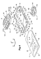
- Figure 3 is an exploded perspective view of the main components of the device of Figure 2;
- Figure 4 is an exploded bottom view of the components illustrated in Figure 3;
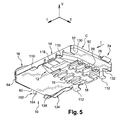
- Figure 5 is a perspective bottom view of the device shown in Figure 2;
- Figure 6 is a perspective bottom view on a larger scale of the device, without a card; and
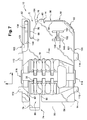
- Figure 7 is a bottom plan view of the device of Figure 6 in which a card is illustrated in dotted lines.
- In the description that follows, identical, analogous or similar elements will be denoted by the same reference numbers.
- To simplify the understanding of the description and of the claims, the terms "vertical", "horizontal", "rear", "front", "lower", "upper", "longitudinal" and "transverse" with respect to the appended drawings and to the L,V,T coordinate system indicated thereon will be used (but implying no limitation).
- The device or
connector 10 illustrated in the figures essentially consists of a lower insulating support in the form of a horizontal mouldedplastic plate 12, an attachedupper cover 14, which is a metal part, for example made of cut, folded and/or stamped sheet metal, and anupper ejection spring 16. - The
device 10 is designed to receive a card C, which is an integrated-circuit card, for example of the MICROSIM type illustrated in the figures. - The
support 12 is a moulded part with the general shape of a rectangular parallelepipedal plate, which is bounded vertically by alower plane face 18 and anupper plate face 20. - The
lower plate 12 is also bounded transversely by twolongitudinal edges transverse edge 26 and by a reartransverse edge 28. - The
lower plate 12 made of insulating material defines, with the attachedupper cover 14, a housing orcavity 30 which has a shape complementary to that of the card C and is intended to at least partly house the latter, thelower face 32 of which has conductingpads 34 which, when the card C is in the inserted position - or contact position - in thecavity 30 of the device, are in contact with thefree contact ends 36 belonging tocontact blades 38 carried by thelower plate 12. - The
cavity 30 is generally open longitudinally at the front and at the rear. Thecavity 30 is bounded transversely by the parallel opposedinternal faces lateral flanges upper cover 14, which are spaced apart transversely by a distance corresponding approximately to the width of the card C, so as to guide the opposed parallellongitudinal edges cavity 30. - The cavity is bounded vertically downwards by the horizontal
upper face 20 of thelower plate 12. - The
upper cover 14 essentially consists of a horizontalupper plate 46 which has a generally rectangular shape and is bounded transversely by two opposed parallellongitudinal edges transverse edge 52 and by a reartransverse edge 54. - The overall dimensions of the
upper plate 46 are such that, as may be seen in Figure 7, it covers substantially all of the card C, whereas the overall length of thelower plate 12 between itstransverse edges 29 and 28 is considerably less, and around one-third of the length of the card. - The front
transverse edge 52 of theplate 46 is extended vertically downwards by a folded-over fronttransverse sheet 56, the rearinternal face 58 of which constitutes a longitudinal mechanical stop face that defines thecavity 30 longitudinally towards the front and against which the card C butts, via its fronttransverse edge 60, in order to define its inserted and contact position in thedevice 10, and especially with respect to thelower plate 12 that bears the contact elements that cooperate with thepads 34 on thelower face 32 of the card C. - The front
transverse edge 52 is also extended vertically downwards by a folded-overedge 62, which constitutes a cut corner at approximately 45° relative to the longitudinal direction I of insertion of the card C into thecavity 30, and this 45° inclination corresponds to that of the standardizedcut corner 64 formed in the fronttransverse edge 60 of the MICROSIM card. Thus, the 45° folded-overedge 62 constitutes a polarization means for the correct sense and orientation of the card C in thedevice 10. - The folded-over
edge 62 and thetransverse sheet 56 do not extend over the entire transverse width of theedge 52 and the free part of the latter includes a cut-out orslot 66 that emerges longitudinally towards the front and is bounded transversely by a straightlongitudinal edge 68 and by a convex circularly arcuatelongitudinal edge 70, the rear ends of the twoedges rear end edge 72 in the form of a concave semicircle, which defines theslot 66 longitudinally rearwards. - The retractable means 74 for retention of the card C in the
cavity 30 consists here of a retention spur orlip 76 which is placed at the rearfree end 78 of acarrier arm 80 that is produced as a single part with theupper plate 46 of thecover 14. - More particularly, the
carrier arm 80 is a portion of theupper plate 46 and is formed, in the said plate, by means of two straight parallellongitudinal slots transverse edge 54 of theupper plate 46. - The L-
shaped retention lip 76 is also produced as one part with the rearfree end 78 of thearm 80, being jointed horizontally to the latter. - In its free state and when a card is in the inserted contact position, the
retention lip 76 extends below the plane of the internallower face 86 of theupper plate 46 so that its front transverse edge constitutes a stop facet that extends vertically into thecavity 30 and faces the reartransverse edge 90 of the card C. - The
carrier arm 80 behaves in the manner of an elastically deformable beam, which can flex vertically, from its free rest state, especially upwards, the "hinge" of thecarrier arm 80 consisting of aregion 92 located near the front base of thecarrier arm 80. - In order to intentionally cause elastic deformation of the
carrier arm 80 from its free rest state, this arm is provided with a gripping or actuatingtab 94 which extends longitudinally rearwards beyond thelip 76. - The gripping or actuating
tab 94 thus allows thecarrier arm 80, and therefore theretractable retention lip 76, to rise vertically so that it no longer extends vertically inside thecavity 30 facing the reartransverse edge 90 of the card C when the latter is in position in thedevice 10. - The rear
free end edge 98 of thecarrier arm 80 constitutes a cam profile - in the form of a chamfer or inclined corner - which cooperates with the fronttransverse edge 60 of the card C when the latter is inserted longitudinally, from the rear forwards, so as to make theretention lip 76 automatically move away by elastic deformation of thecarrier arm 80. - In particular in order for the
metal cover 14 to be mounted on and fastened to the insulating support 12 - in its mounted position, which is illustrated in particular in Figures 2 to 5 and 7 - thecover 14 includes two folded-overlongitudinal flanges longitudinal edges upper plate 46, along the external verticallongitudinal faces lower plate 12. - The longitudinal
lower edges flanges horizontal tabs - The
lateral flanges cover 14 also include, in their rear half, twotabs lower plate 12 that carries the contact elements. - Near its lower longitudinal edge, each
mounting tab 114 has ahorizontal slot key lower plate 12, each of the externallateral faces complementary hole lower plate 12. - Thus, in order for the cap or
cover 14 to be mounted on and fastened to theplate 12, thecover 14 is placed, vertically downwards when considering Figure 3, on top of theplate 12 and then thekeys slots holes corresponding hole - The
plate 12/cover 14 assembly operation may be carried out before thedevice 10 is mounted on a printed-circuit board (PCB) of an electronic apparatus, so as to form a single entity. - The mounting operation may also consist in fastening, in a known manner, by soldering or brazing, firstly the
plate 12 to the printed-circuit board, then in placing thecover 14 on top of theplate 12 and fastening thecover 14 by means of thekeys - Each
lateral flange branch cavity 30. - Finally, the
cover 14 has, at its right front longitudinal end, alongitudinal tab 134 which is folded transversely inwards and can move vertically under the action of the fronttransverse edge 60 of the card C so as to constitute the moving contact of a switch for detecting the presence of a card in the inserted position. - For this purpose, the moving
contact 134 comprises aramp 136 with which theedge 60 of the card cooperates, and its frontfree end edge 138 is, when a card C is present, capable of coming into contact with a corresponding track on the printed-circuit board (PCB) on which thedevice 10 is mounted in order to establish an electrical switching wave. - The
tap 134 operates, like thearm 80, in the manner of a longitudinal electrical beam whose pivot axis is located at its rearlongitudinal end 140. - According to the teachings of the invention, the
spring 16 for ejecting the card out of thecavity 30 of thedevice 10 is a spring made of wire of circular cross section, produced by bending, the said spring being placed on the outside of thedevice 10, above theupper plate 46 of thecover 14. - As may be seen in the figures, the spiralled
spring 16 here has two complete circular turns that lie in the same horizontal plane and are adjacent to theupper face 47 of theupper plate 46. - The radially
innermost turn 142 is extended by afree end portion 144 which has a diametral orientation and is, in the embodiment illustrated in the figures, in the mounted position of thespring 16, oriented longitudinally. - This
end 144 is housed, by interlocking, in acomplementary receptacle 146 formed in theupper plate 46, near the front longitudinal end of the latter, by means of a plunged boss which is bounded by two cut parallel transverse slots, a rear 148 and a front 150, the plunged boss being produced by upward drawing so as to form an upper half-loop 152 of semicircular cross section complementary to the circular cross section of the constituent wire of thespring 16. - The dimensions of the
receptacle 146 are such that, in the mounted position, thespring 16 is pressed horizontally onto theupper face 47 of theupper plate 46 of thecover 14. - The mounting operation is effected by elastic deformation of the
strand 144 downwards out of the plane of the turns in order to insert it into the half-loop 152, then the strand is inserted and finally held captive when the turns bear on theface 47. - The second, radially outermost, turn 154 is extended tangentially and horizontally by a connecting strand or
portion 156 that extends generally at 45° towards the front and thefree end 158 of which is extended by a right-angled or 90°bend 160 in order to be extended by a verticalmain ejection strand 162 that extends vertically downwards inside thecavity 30 and is housed in theslot 66. - The design of the
spring 16 is such that, in the mounted and rest position, that is to say in the absence of the card C, the rear convex cylindrical lateral wall of themain ejection strand 162 is urged, by prestressing, against theend wall 72 of theslot 66, that is to say it is permanently urged elastically towards this rest position. - The lower
free end portion 164 of thestrand 162 constitutes the active portion of theejection spring 16 with which the front transverse edge of the card C cooperates when the latter is inserted into thedevice 10. - Thus, referring to Figure 7, the insertion of the card in the direction I firstly causes the
lip arm 80 to retract, until the fronttransverse edge 60 reaches the dimension of theend wall 72 of theslot 66, and therefore theportion 164. - The user then continues to apply the insertion force, from left to right, against the turn force or ejection force exerted by the
strand 164 of theejection spring 16, which is progressively strained while still pushing longitudinally forwards onto thestrand 164. - The movement of the
strand 164 takes place generally along the longitudinal direction, from the rear forwards, and along a circularly arcuate path approximately parallel to the profile of the convex circularlongitudinal edge 70 of the cut-out 66. - During the insertion, the
active portion 164 also moves slightly, downwards when referring to Figure 7, along the transversefront end edge 60 of the card C. - The insertion is completed when the card C has reached its inserted position shown by the dotted lines in Figure 7, in which it is held in place by the
lip transverse edge 90. - The card is automatically ejected by retracting, vertically upwards, the
retention lip 76 and through the action of theactive portion 164 of theejection spring 16, which cooperates with the fronttransverse edge 60 in order to eject the card C longitudinally rearwards. - As may be seen in particular in Figure 7, the design according to the invention is particularly advantageous insofar as the
device 10 hardly extends longitudinally forwards beyond the fronttransverse edge 60 of the card, that is to say its dimension in this direction corresponds to its position of the fronttransverse edge 60 to which the diameter of the wire of theactive portion 164 of theejection spring 16 is added, while still having a very high ejection force.
Claims (12)
- Device (10) for connecting a card (C) to a contact-type integrated-circuit card (C), which card has conducting pads (34) on its lower main face (32) and is longitudinally bounded by a front transverse edge (60) and a rear transverse edge (90), of the type comprising:characterized in that the body (142, 154) of the ejection spring (16) is placed outside of the casing above the cover (14, 46, 47), and in that the upper plate (46) of the cover includes a slot (66) for the passage of a portion of the main ejection strand (162), of generally vertical orientation, in which slot said portion can move in a generally longitudinal direction.a casing (12, 14) which defines a cavity (30), an open rear end of which allows the card (C) to be at least partly introduced thereinto, longitudinally from the rear forwards, and which includes a lower plate (12) made of insulating material with an upper face (20) facing upwards and an upper cover (14) having a horizontal upper plate (46);electrical contact elements (36) carried by the lower plate (12) and the contact ends of which elements (36) extend inside the cavity (30), above the said upper face, in order to cooperate with the pads (34) on the card (C);a spring (16) for ejecting the card (C) out of the cavity (30), which comprises a main ejection strand (162), the active end portion (164) of which is located inside the cavity (30) in order to cooperate with a facing portion of the front transverse edge (60) of the card (C) so as to push the latter rearwards out of the cavity; andmeans (80, 76) for retaining the card (C) in the cavity against the ejection force applied to the card by the ejection spring (16, 164),
- Device according to the preceding claim, characterized in that the ejection spring (16) is a spring wound in a spiral (142, 154), the body of which has at least one circular horizontal turn adjacent to the upper face (47) of the upper plate (46).
- Device according to the preceding claim, characterized in that the free end portion (144) of the radially innermost turn (142) of the body of the ejection spring (16) is fastened to the upper plate (46) and in that the free end portion (156) of the radially outermost turn (154) is extended at right angle (160), vertically downwards, through the said slot (66) in order to form the said main ejection strand (162, 164).
- Device according to either of Claims 2 and 3, characterized in that the ejection spring (16) is a spring made of wire with a circular cross section.
- Device according to any one of the preceding claims, characterized in that the said slot (66) is bounded longitudinally rearwards by an end wall (72) against which, in the absence of the card, the said main ejection strand (162, 164) bears elastically.
- Device according to any one of the preceding claims, characterized in that the upper plate (46) is a part made of cut, folded and/or stamped sheet metal.
- Device according to the preceding claim taken in combination with Claim 3, characterized in that the free end portion (144) of the radially innermost turn (142) of the body of the ejection spring (16) is fastened in a receptacle (146) in the upper plate (46), which receptacle is made as one piece with the upper plate, especially by means of a plunged boss (148, 150, 152).
- Device according to any one of the preceding claims, characterized in that the upper plate (46) includes a retractable device (74, 76, 80) for retention of the card (C) in the inserted position in the cavity (30), which device is produced as one piece with the upper plate (46).
- Device according to the preceding claim, characterized in that the retractable retention device has a retention lip (76) that is carried by an elastically deformable arm (80) of the upper plate (46), this arm having a stop (78) that normally lies facing the rear transverse edge (90) of the card, which lip (76) can be moved, by elastic deformation of the arm (80) that carries the lip, towards a retracted position in which the card (C) can be longitudinally ejected, at least partially, by the ejection spring (16).
- Device according to any one of the preceding claims, characterized in that the upper cover includes two opposed vertical longitudinal flanges (100, 102) that extend the upper plate (46) downwards, the lower plate (12) being received between the flanges and the facing internal faces (101, 103) of which flanges define the cavity (30) laterally and constitute longitudinal guiding faces for the card (C).
- Device according to the preceding claim, characterized in that each of the longitudinal flanges (100, 102) includes means (114, 116, 118, 120) for fastening the cover (14) to the lower plate (12).
- Device according to the preceding claim, characterized in that the means for fastening the cover (14) to the lower plate (12) comprise two opposed transverse keys (122, 124), each of which extends through a slot (118, 120) of an associated flange (100, 102), each key being received in a complementary hole (126, 128) formed in the lower plate (12, 22, 24).
Applications Claiming Priority (2)
| Application Number | Priority Date | Filing Date | Title |
|---|---|---|---|
| FR0313635A FR2862784B1 (en) | 2003-11-21 | 2003-11-21 | DEVICE FOR THE ELECTRICAL CONNECTION OF A CHIP CARD |
| FR0313635 | 2003-11-21 |
Publications (1)
| Publication Number | Publication Date |
|---|---|
| EP1536366A2 true EP1536366A2 (en) | 2005-06-01 |
Family
ID=34451662
Family Applications (1)
| Application Number | Title | Priority Date | Filing Date |
|---|---|---|---|
| EP04105572A Withdrawn EP1536366A2 (en) | 2003-11-21 | 2004-11-08 | Device for the electrical connection of a chip card |
Country Status (4)
| Country | Link |
|---|---|
| US (1) | US6984140B2 (en) |
| EP (1) | EP1536366A2 (en) |
| JP (1) | JP2005158745A (en) |
| FR (1) | FR2862784B1 (en) |
Families Citing this family (7)
| Publication number | Priority date | Publication date | Assignee | Title |
|---|---|---|---|---|
| KR101349639B1 (en) * | 2007-06-04 | 2014-01-09 | 타이코 일렉트로닉스 저팬 지.케이. | A memory card and a SIM card mounting socket having a sensing switch |
| TWM370233U (en) * | 2009-05-12 | 2009-12-01 | Hon Hai Prec Ind Co Ltd | Electrical connector assembly |
| US8544745B2 (en) | 2011-03-03 | 2013-10-01 | Genesis Technology Usa, Inc. | Heat-dissipating card connector |
| US8651884B1 (en) | 2012-04-10 | 2014-02-18 | Google Inc. | Ejectable memory card tray in a universal serial bus (USB) connector |
| TWM482876U (en) * | 2014-01-17 | 2014-07-21 | Wistron Corp | Electronic card connector and electronic device installed with the same |
| US9395770B1 (en) * | 2015-08-27 | 2016-07-19 | Yuyi Lee | Retractable data and power system having an inner carriage side panel with a latch with a round slot and an angled slot |
| US10855028B1 (en) * | 2019-07-29 | 2020-12-01 | Te Connectivity Corporation | Plug connector |
Family Cites Families (6)
| Publication number | Priority date | Publication date | Assignee | Title |
|---|---|---|---|---|
| US4436269A (en) * | 1980-11-28 | 1984-03-13 | The Procter & Gamble Company | Dispenser suspension means employing planar spring-loaded detent |
| US6382995B1 (en) * | 1999-05-20 | 2002-05-07 | Itt Manufacturing Enterprises, Inc | Smart card connector with retain and eject means |
| US6220882B1 (en) * | 1999-11-15 | 2001-04-24 | Molex Incorporated | IC card connector with release means |
| FR2805401A1 (en) * | 2000-02-18 | 2001-08-24 | Itt Mfg Enterprises Inc | ERGONOMIC ELECTRICAL CONNECTOR FOR INTEGRATED CIRCUIT (S) CARD |
| FR2816765B1 (en) * | 2000-11-14 | 2003-01-17 | Fci Pontarlier | CHIP CARD CONNECTOR WITH LOCKING MECHANISM |
| JP2003115354A (en) * | 2001-10-04 | 2003-04-18 | Yamaichi Electronics Co Ltd | Card connector |
-
2003
- 2003-11-21 FR FR0313635A patent/FR2862784B1/en not_active Expired - Fee Related
-
2004
- 2004-11-08 EP EP04105572A patent/EP1536366A2/en not_active Withdrawn
- 2004-11-10 US US10/985,468 patent/US6984140B2/en not_active Expired - Fee Related
- 2004-11-22 JP JP2004338028A patent/JP2005158745A/en not_active Withdrawn
Also Published As
| Publication number | Publication date |
|---|---|
| US20050142902A1 (en) | 2005-06-30 |
| US6984140B2 (en) | 2006-01-10 |
| FR2862784A1 (en) | 2005-05-27 |
| FR2862784B1 (en) | 2006-01-21 |
| JP2005158745A (en) | 2005-06-16 |
Similar Documents
| Publication | Publication Date | Title |
|---|---|---|
| US6149466A (en) | Compact smart card electrical connector | |
| US6382995B1 (en) | Smart card connector with retain and eject means | |
| US9960536B2 (en) | Card holding member and card connector | |
| US6075706A (en) | PC card for receiving chip card | |
| US7033221B2 (en) | Connector for high capacity smart cards | |
| EP1602058B1 (en) | Connector for a smart card, comprising an integrated drawer/slider for the card | |
| US5823828A (en) | Smart card connector with slidable cover | |
| EP0889493B1 (en) | Electrical switch assembly | |
| JP3784783B2 (en) | Card connector | |
| JP5181398B2 (en) | Card connector with removal function | |
| JPH0916739A (en) | Contact device for chip cards | |
| EP1783657B1 (en) | Memory card socket structure | |
| US20010032882A1 (en) | Card reader and mobile equipment which has it | |
| US20160028172A1 (en) | Card retention member and card connector | |
| US6692277B2 (en) | Electrical card connector with spring switch | |
| JP2004078968A (en) | Contacting device for chip card device | |
| WO2001022345A1 (en) | Sim card holder | |
| EP1406204B1 (en) | Card holder for cellular phone | |
| US6494745B1 (en) | PC card that receives and guides chip card | |
| US6984140B2 (en) | Smart card connector with ejection spring | |
| JP3429002B2 (en) | Electrical connector for connection of an electronic memory card including an integrated switch for detecting the presence of the card | |
| EP1000406B1 (en) | Connector for connecting a smart card comprising means for automatically ejecting the card | |
| US7048589B2 (en) | Short smart card connector | |
| US7278866B1 (en) | Electrical card connector | |
| US4776805A (en) | Card biasing device for card edge connectors |
Legal Events
| Date | Code | Title | Description |
|---|---|---|---|
| PUAI | Public reference made under article 153(3) epc to a published international application that has entered the european phase |
Free format text: ORIGINAL CODE: 0009012 |
|
| AK | Designated contracting states |
Kind code of ref document: A2 Designated state(s): AT BE BG CH CY CZ DE DK EE ES FI FR GB GR HU IE IS IT LI LU MC NL PL PT RO SE SI SK TR |
|
| AX | Request for extension of the european patent |
Extension state: AL HR LT LV MK YU |
|
| 17P | Request for examination filed |
Effective date: 20050901 |
|
| STAA | Information on the status of an ep patent application or granted ep patent |
Free format text: STATUS: THE APPLICATION IS DEEMED TO BE WITHDRAWN |
|
| 18D | Application deemed to be withdrawn |
Effective date: 20061201 |