EP1536263B1 - High-aperture wide angle cinema projection lens - Google Patents
High-aperture wide angle cinema projection lens Download PDFInfo
- Publication number
- EP1536263B1 EP1536263B1 EP04022369A EP04022369A EP1536263B1 EP 1536263 B1 EP1536263 B1 EP 1536263B1 EP 04022369 A EP04022369 A EP 04022369A EP 04022369 A EP04022369 A EP 04022369A EP 1536263 B1 EP1536263 B1 EP 1536263B1
- Authority
- EP
- European Patent Office
- Prior art keywords
- lens
- projection
- projection lens
- focal length
- positive
- Prior art date
- Legal status (The legal status is an assumption and is not a legal conclusion. Google has not performed a legal analysis and makes no representation as to the accuracy of the status listed.)
- Expired - Fee Related
Links
Images


Classifications
-
- G—PHYSICS
- G02—OPTICS
- G02B—OPTICAL ELEMENTS, SYSTEMS OR APPARATUS
- G02B13/00—Optical objectives specially designed for the purposes specified below
- G02B13/02—Telephoto objectives, i.e. systems of the type + - in which the distance from the front vertex to the image plane is less than the equivalent focal length
-
- G—PHYSICS
- G02—OPTICS
- G02B—OPTICAL ELEMENTS, SYSTEMS OR APPARATUS
- G02B9/00—Optical objectives characterised both by the number of the components and their arrangements according to their sign, i.e. + or -
- G02B9/64—Optical objectives characterised both by the number of the components and their arrangements according to their sign, i.e. + or - having more than six components
Definitions
- the invention relates to a high-aperture projection lens with focal lengths shorter than 50 mm.
- the main field of application of the invention is the 35 mm cinema projection.
- Projection objectives for the projection of cinema images must meet a number of technical constraints that affect the selection and arrangement of the optical elements.
- installation conditions relate, for example, to the spatial limitations of the space available for the projection objective given by commercial cinema projectors.
- the diameters of the optical elements used, the housing of the projection lens and the focal distance, ie the distance of the last lens surface from the film plane, must satisfy the installation conditions.
- projection lenses For small cinemas with large screens or for rear projection usually wide-angle projection lenses are required. In many cases, the total focal length of the projection lens is shorter than the specified by the installation conditions kerf. Such projection lenses are referred to as retrofocus projection lenses.
- the entrance pupil D EP is here defined as the opening of the projection lens that a viewer perceives from the direction of the film. As a rule, this is the image of a diaphragm within the projection lens. A large opening D EP thus causes a small f-number k and vice versa.
- the light source used for the projection also has a specific f-number k SP .
- a parabolic or spherical mirror with focal length f SP and edge diameter D SP is used for the illumination, it is possible to calculate a f-number k SP of the mirror from the ratio of these two quantities.
- the f-number of the projection lens is adjusted to the f-number of the mirror to reduce light losses in the projection lens (too small opening) or insufficient illumination (too large opening) to avoid.
- EP 1 134 606 B1 is a projection lens described, which is composed of at least seven on both sides of air adjacent lenses.
- the projection objective has a f-number of 1.9 and is characterized by an arrangement of lenses whose first lens viewed from the image side is designed as a positive lens.
- a bright wide-angle lens with large image-side cut which is composed of at least seven, but usually nine or ten on both sides of adjacent air lenses.
- the wide-angle objective is characterized by an arrangement of lenses whose first lens viewed from the image side is designed as a negative meniscus lens, a second lens as a positive meniscus lens and a third lens as a negative meniscus lens.
- the projection lens is designed as a lightweight retrofocus projection lens. This is achieved by the first two lenses, which have an overall negative focal length. Furthermore, the smallest f-number k min of the projection lens must be 1.8 or less (ie, k min ⁇ 1.8).
- the entrance pupil is defined as the opening of the projection lens, which perceives a fictitious, film-side positioned observer.
- the projected image is optimally illuminated even in its peripheral areas.
- the entrance pupil is arranged closer than at a distance of 100 mm, a bundle of rays emanating from an outer pixel on the same side of the optical axis as the pixel on its side remote from the optical axis is cut by the entrance pupil. Thereby light losses occur.
- the entrance pupil is arranged at a distance of more than 300 mm, the same beam on the side of the optical axis opposite to the pixel is truncated on its side remote from the optical axis by the entrance pupil.
- the projection objective has a diaphragm, in particular a variable diaphragm, between the second positive lens and the third biconvex lens.
- a diaphragm in particular a variable diaphragm, between the second positive lens and the third biconvex lens.
- the diaphragm is arranged at a position at which all beams originating from the binder have a symmetrical cross-section with respect to the optical axis. This ensures that no additional edge effects and shadowing (vignetting) occur through the aperture.
- an aspheric surface is used to correct aberrations, then it makes sense to arrange the aspherical surface on a surface adjacent to the diaphragm. Then, the aspherical surface allows optimal correction of the spherical aberrations at high f-number of the projection lens.
- optical elements typically consist of the lenses customary for the construction of projection objectives or plastics, which are selected with regard to their refractive index and their dispersion properties.
- the proposed projection lens has the advantage that it is also suitable for projectors with high-open illumination mirrors (eg with a f-number of the mirror k sp of 1.7), since the aperture angle u of the projection lens is adapted to the aperture angle ⁇ of the illumination mirrors can. As a result, the light emanating from the illumination mirror is used optimally. At the same time, the projection lens has a relatively long focal length.
- the described construction of the projection lens can be further improved by a number of optional additional features in its optical properties. These optional additional features are described below.
- the aspherical surface does not deviate by more than 10 ⁇ m from a spherical surface.
- the small deviation of the surface from the spherical shape i. E., Only 4-7 microns
- the optical quality inspection of the surface can be greatly simplified, since a test of the surface with expensive holograms can be omitted.
- a further improvement of the projection objective can be achieved by designing the projection objective in such a way that the following condition is fulfilled between the overall length Sumd, the focal distance S'F 'and the total focal length f' of the projection objective: 2 . 8th ⁇ f ' ⁇ Sumd + S'F' ⁇ 4 . 5 ⁇ f '
- the length Sumd designates the distance between the first canvas-side lens surface and the last film-side lens surface.
- the condition (3) is the result of an optimization between uniform illumination of the image and too long a length.
- Sumd + S'F' ⁇ 2 . 8th ⁇ f ' As a result of insufficient illumination and / or excessive vignetting light losses and thus losses in the light intensity of the projection lens would occur. Furthermore, for too small cutting widths, the distance between the projection lens and the film plane would be less than prescribed by the installation conditions. In the case Sumd + S'F' ⁇ 4 . 5 ⁇ f ' however, too thick and expensive lens systems would have to be used so that the transmission of the entire system and thus the light intensity decreases.
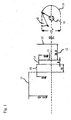
- Fig. 1 Boundary curves of the projection objective housings of two widespread cinema projectors (Ernemann Cine Tec GmbH and Fa. Kinoton GmbH) are shown as examples of typical installation conditions for projection objectives.
- the distance S'F '(in Fig. 1 designated 12) a first lens system with a maximum rim diameter 14 of 40 mm and a total thickness of 8 mm are arranged.
- a second lens system with a maximum rim diameter 16 of 46 mm and a total thickness of 15 mm can be arranged.
- a third lens system can have a maximum edge diameter 17 of 70.65 mm.
- a projection lens is designed so that the lens system meets the installation conditions of both manufacturers.
- the opening angle ⁇ of the cone of light emitted by the light source 18 and reflected by the illumination mirror 19 light illustrates.
- the f-number k SP is the ratio between the focal length f SP (not shown in FIG Fig. 1 ) and the diameter D SP of the mirror.
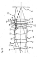
- Fig. 2 shows the basic structure of a projection lens according to a first embodiment. It is about a projection lens with a focal length of 35 mm and a minimum f-number of 1.7.
- the optical axis is designated 34. Between the second positive lens 22 and the third positive lens 24, a shutter 64 is arranged.
- the specified projection lens When the iris is open, the specified projection lens has a f-number of 1.7. So it can also extremely high open illumination mirror with an opening angle up to about 17 ° used as a light source and used efficiently.
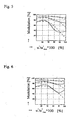
- Fig. 3 shows the resolution of the projection lens according to the first embodiment.
- the field curvature correction must take into account the curvature of the film at the edge in the direction of the projection objective of 0.1 to 0.15 mm caused by the large heat development of the projection lamp.
- the illustrated modulation transfer functions are calculated for such a curved film.
- the resolution was calculated for a color weight corresponding to the mean sensitivity of the human eye.
- Three examples were calculated: the upper two curves belong to the example with a spatial frequency of 20 line pairs per mm (LP / mm), the middle two curves to 40 LP / mm and the lower two curves to 80 LP / mm.
- the solid line shows the resolution of radial line pairs and the dashed line the resolution of tangent line pairs.
- the x-axis indicates the relative deviation from the center of the image to be magnified. On the y-axis, the modulation transfer function is shown at a f-number k of 1.7. The picture was almost infinite.
- the resolution of the projection lens according to the first embodiment corresponds to the resolution of very good projection objectives.
- FIG. 12 shows the relative illuminance of the edges of the enlarged image compared with the center for the projection lens according to the first embodiment.
- FIG. The x-axis corresponds to the x-axis according to Fig. 3 .
- Fig. 8 shows the distortion for the projection lens according to the first embodiment in% of the deviation from the ideal image size.
- Fig. 9 is the transmission in% for the projection lens according to Fig. 2 for the wavelength range between 400 nm and 700 nm.
- the cinema projection lens has tolerable losses in the visible wavelength range.
- the cinema projection lens according to the first embodiment has a cutting width S'F 'of 31.898 mm.
- the overall length Sumd of the entire projection lens is 90.647 mm.
- the sum of length and cutting width is thus 122.545 mm and is thus greater than 2.8 f '(98 mm) and less than 4.5 f' (157.5 mm). The above condition (3) is thus satisfied.
- the entrance pupil is located 119.87 mm to the left of the lens surface 62, so that the condition of the position of the entrance pupil is met.
- the aperture 64 facing surface 130 of the lens 112 is again designed as an aspherical surface.
- the aspheric coefficients of this surface 130 are listed in Tab.
- the projection objective specified in the second exemplary embodiment also has a f-number of 1.7, so that once again extremely high-opening illumination mirrors can be used.
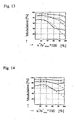
- FIGS. 11 to 14 correspond to the FIGS. 3 to 6 of the first embodiment and show the resolution of the projection lens according to the second embodiment at apertures k of 1.7, 2.0, 2.8 and 4.0.
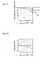
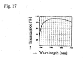
- FIGS. 15 to 17 according to the FIGS. 7 to 9 of the first embodiment and in turn show the relative illuminance, the distortion and the transmission of the cinema projection lens according to the second embodiment.
- the cinema projection lens according to the second embodiment has a focal length S'F '12 of 40.002 mm and a length Sumd of 101.943 mm.
- the total of cut and length is thus 141.945 mm and is thus greater than 2.8f '(133 mm) and less than 4.5f' (213.75 mm).
- the entrance pupil is located 233.521 mm to the left of the last lens surface 150, so that the condition of the position of the entrance pupil is also met by the projection objective according to the second embodiment.
- Tab. 1 numeral Radius / mm Thickness or distance / mm Free diameter / mm Refractive index (n d ) at 588 nm Dispersion ( ⁇ d ) at 588 nm 36 76.068 36.100 20 10.521 1.51680 64.14 38 21.464 26,800 13.354 40 -126.324 24,500 22 13.711 1.72916 54.65 42 -52,802 * 26,600 5,000 64 (Cover) 6,089 44 29.103 29,000 24 16.346 1.64050 60.15 46 -51.643 27,200 4,476 48 -29.981 24,800 26 1,800 1.59270 35,30 50 26.691 24,800 4,000 52 -153.321 24,800 32 1,800 1.80809 22,75 54 63.875 26,400 1,650 56 169.672 27,500 30 4,800
Description
Die Erfindung betrifft ein hoch geöffnetes Projektionsobjektiv mit Brennweiten kürzer als 50 mm. Hauptanwendungsgebiet der Erfindung ist die 35 mm Kinoprojektion.The invention relates to a high-aperture projection lens with focal lengths shorter than 50 mm. The main field of application of the invention is the 35 mm cinema projection.
Projektionsobjektive für die Projektion von Kinobildern müssen eine Reihe technischer Randbedingungen erfüllen, welche die Auswahl und Anordnung der optischen Elemente beeinflussen. Neben einer hohen Lichtstärke, guter Abbildungsqualität und hoher Schärfentiefe sind auch Einbaubedingungen zu erfüllen. Diese Einbaubedingungen beziehen sich beispielsweise auf die durch kommerzielle Kinoprojektoren vorgegebenen räumlichen Begrenzungen des für das Projektionsobjektiv verfügbaren Raums. So müssen die Durchmesser der verwendeten optischen Elemente, das Gehäuse des Projektionsobjektivs und die Schnittweite, also der Abstand der letzten Linsenoberfläche von der Filmebene, den Einbaubedingungen genügen.Projection objectives for the projection of cinema images must meet a number of technical constraints that affect the selection and arrangement of the optical elements. In addition to high luminous intensity, good image quality and high depth of field, installation conditions must also be met. These installation conditions relate, for example, to the spatial limitations of the space available for the projection objective given by commercial cinema projectors. Thus, the diameters of the optical elements used, the housing of the projection lens and the focal distance, ie the distance of the last lens surface from the film plane, must satisfy the installation conditions.
Für kleine Kinosäle mit großen Leinwänden oder für die Rückprojektion sind in der Regel Weitwinkel-Projektionsobjektive erforderlich. In vielen Fällen ist die Gesamtbrennweite des Projektionsobjektivs kürzer als die durch die Einbaubedingungen vorgegebene Schnittweite. Derartige Projektionsobjektive werden als Retrofokus-Projektionsobjektive bezeichnet.For small cinemas with large screens or for rear projection usually wide-angle projection lenses are required. In many cases, the total focal length of the projection lens is shorter than the specified by the installation conditions kerf. Such projection lenses are referred to as retrofocus projection lenses.
Neben optischen Abbildungsfehlern treten in vielen Projektionsobjektiven Probleme mit der gleichmäßigen Ausleuchtung des Bildes und der Lichtstärke der Anordnung auf. Ein Maß für die Lichtstärke des Projektionsobjektivs ist die sog. Blendenzahl k, welche sich aus der Gesamtbrennweite f' des Projektionsobjektivs und dem Durchmesser der Eintrittspupille DEP berechnet entsprechen![]()
![]()
Die Eintrittspupille DEP ist hier als diejenige Öffnung des Projektionsobjektivs definiert, die ein Betrachter aus Richtung des Films wahrnimmt. In der Regel handelt es sich dabei um das Abbild einer Blende innerhalb des Projektionsobjektivs. Eine große Öffnung DEP bewirkt also eine kleine Blendenzahl k und umgekehrt.The entrance pupil D EP is here defined as the opening of the projection lens that a viewer perceives from the direction of the film. As a rule, this is the image of a diaphragm within the projection lens. A large opening D EP thus causes a small f-number k and vice versa.
Gleichzeitig weist aber auch die für die Projektion verwendete Lichtquelle eine bestimmte Blendenzahl kSP auf. Wenn beispielsweise für die Beleuchtung ein parabolischer oder sphärischer Spiegel mit Brennweite fSP und Randdurchmesser DSP eingesetzt wird, so lässt sich aus dem Verhältnis dieser beiden Größen eine Blendenzahl kSP des Spiegels berechnen. Im Idealfall ist die Blendenzahl des Projektionsobjektivs der Blendenzahl des Spiegels angepasst, um Lichtverluste im Projektionsobjektiv (zu kleine Öffnung) oder ungenügende Ausleuchtung (zu große Öffnung) zu vermeiden.At the same time, however, the light source used for the projection also has a specific f-number k SP . If, for example, a parabolic or spherical mirror with focal length f SP and edge diameter D SP is used for the illumination, it is possible to calculate a f-number k SP of the mirror from the ratio of these two quantities. Ideally, the f-number of the projection lens is adjusted to the f-number of the mirror to reduce light losses in the projection lens (too small opening) or insufficient illumination (too large opening) to avoid.
In
In der
Aufgabe der Erfindung ist es, ein Projektionsobjektiv mit hervorragender Abbildungsleistung anzugeben,
- welches die handelüblichen Einbaubedingungen erfüllt,
- welches eine Brennweite zwischen 28,0 und 47,5 mm aufweist, und
- dessen Blendenzahl k an die Blendenzahl hoch geöffneter Beleuchtungsspiegel angepasst ist.
- which complies with the usual commercial installation conditions,
- which has a focal length between 28.0 and 47.5 mm, and
- whose f-number k is adapted to the f-number of high-aperture illumination mirrors.
Diese Aufgabe wird durch die Erfindung mit den Merkmalen des unabhängigen Anspruchs gelöst. Vorteilhafte Weiterbildungen der Erfindungen sind in den Unteransprüchen gekennzeichnet.This object is achieved by the invention with the features of the independent claim. Advantageous developments of the inventions are characterized in the subclaims.
Es wird ein Projektionsobjektiv vorgeschlagen, welches dazu geeignet ist, einen Film auf eine Leinwand zu projizieren und in der angegebenen Reihenfolge von der Leinwand aus betrachtet aus folgenden Elementen besteht:
- eine erste negative Linse,
- eine zweite positive Linse,
- eine dritte bikonvexe Linse,
- eine vierte bikonkave Linse,
- eine fünfte bikonkave Linse,
- eine sechste bikonvexe Linse und
- eine siebte bikonvexe Linse.
- a first negative lens,
- a second positive lens,
- a third biconvex lens,
- a fourth biconcave lens,
- a fifth biconcave lens,
- a sixth biconvex lens and
- a seventh biconvex lens.
Es handelt sich um ein Weitwinkel-Projektionsobjektiv, d. h. die Gesamtbrennweite f' des Projektionsobjektivs soll die Bedingung ![]()
![]()
Um eine optimale Korrektur der sphärischen Aberration, besonders bei der kleinen Blendenzahl von k=1,7 zu erzielen, muss mindestens eine Linse des Projektionsobjektivs eine asphärische Oberfläche aufweisen. Es hat sich dabei als zwingend erwiesen, dass die der dritten bikonvexen Linse zugewandte Oberfläche der zweiten positiven Linse als asphärische Oberfläche ausgestaltet ist.In order to achieve an optimal correction of the spherical aberration, especially at the small f-number of k = 1.7, must at least one lens of the projection lens having an aspherical surface. It has proven to be imperative that the third biconvex lens facing surface of the second positive lens is designed as an aspherical surface.
Weiterhin hat es sich als zwingend erwiesen, die Art und Anordnung der Linsen so zu wählen, dass die Eintrittspupille zwischen 100 mm und 300 mm leinwandseitig von der am weitesten filmseitig angeordneten Linsenoberfläche des Projektionsobjektivs entfernt angeordnet ist. Dabei ist die erste negative Linse des Projektionsobjektivs leinwandseitig und die siebte bikonvexe Linse filmseitig angeordnet. Die Eintrittspupille ist dabei als diejenige Öffnung des Projektionsobjektivs definiert, die ein fiktiver, filmseitig positionierter Beobachter wahrnimmt.Furthermore, it has proven to be imperative to choose the type and arrangement of the lenses so that the entrance pupil between 100 mm and 300 mm is located on the screen side away from the most film side lens surface of the projection lens. In this case, the first negative lens of the projection lens is arranged on the canvas side and the seventh biconvex lens is arranged on the film side. The entrance pupil is defined as the opening of the projection lens, which perceives a fictitious, film-side positioned observer.
Dies hat den Vorteil, dass das projizierte Bild auch in seinen Randbereichen optimal ausgeleuchtet wird. Wird die Eintrittspupille näher als in einem Abstand von 100 mm angeordnet, so wird ein von einem äußerten Bildpunkt ausgehendes Strahlenbündel auf der selben Seite der optischen Achse wie der Bildpunkt auf seiner von der optischen Achse entfernt liegenden Seite durch die Eintrittspupille beschnitten. Es treten dadurch Lichtverluste auf. Wird die Eintrittspupille andererseits in einem Abstand von mehr als 300 mm angeordnet, so wird das selbe Strahlenbündel auf der zum Bildpunkt gegenüberliegenden Seite der optischen Achse auf seiner von der optischen Achse entfernt liegenden Seite durch die Eintrittspupille beschnitten.This has the advantage that the projected image is optimally illuminated even in its peripheral areas. If the entrance pupil is arranged closer than at a distance of 100 mm, a bundle of rays emanating from an outer pixel on the same side of the optical axis as the pixel on its side remote from the optical axis is cut by the entrance pupil. Thereby light losses occur. On the other hand, if the entrance pupil is arranged at a distance of more than 300 mm, the same beam on the side of the optical axis opposite to the pixel is truncated on its side remote from the optical axis by the entrance pupil.
Eine weitere zwingende Ausgestaltung des Projektionsobjektivs betrifft die Einbaubedingungen. Die Durchmesser des Projektionsobjektivs müssen so klein ausgebildet sein, dass das Projektionsobjektiv für alle gängigen Kinoprojektoren eingesetzt werden kann. Das Projektionsobjektiv ist daher vorteilhafter Weise in seinen räumlichen Abmessungen derart ausgebildet, dass es zum Betrieb in einen Raum mit den folgenden Abmessungen eingebaut werden kann:
- der Raum ist rotationssymmetrisch um die optische Achse ausgebildet;
- er beginnt in einer ersten Ebene, die senkrecht zur optischen Achse ausgebildet ist und 30 mm von der Filmebene entfernt angeordnet ist;
- leinwandseitig schließt sich an die erste Ebene ein erstes zylindrisches Volumen mit
einem Durchmesser von 40 mm und einerHöhe von 8 mm an; - an das erste zylindrische Volumen schließt sich leinwandseitig ein zweites zylindrisches Volumen mit
einem Durchmesser von 46 mm und einerHöhe von 15 mm an; und - an das zweite zylindrische Volumen schließt sich leinwandseitig ein drittes zylindrisches Volumen mit
einem Durchmesser von 70,65 mm an.
- the space is rotationally symmetrical about the optical axis;
- it begins in a first plane, which is perpendicular to the optical axis and located 30 mm away from the film plane;
- On the linen side, the first level is followed by a first cylindrical volume with a diameter of 40 mm and a height of 8 mm;
- the first cylindrical volume is followed by a second cylindrical volume, on the side of the wall, with a diameter of 46 mm and a height of 15 mm; and
- the second cylindrical volume is followed by a third cylindrical volume with a diameter of 70.65 mm on the linen side.
Das Projektionsobjektiv weist zwischen der zweiten positiven Linse und der dritten bikonvexen Linse eine Blende, insbesondere eine variable Blende, auf. Dies hat den Vorteil, dass gegebenenfalls durch Abblenden eine größere Schärfentiefe erreicht werden kann. Dies ist insbesondere bei gekrümmten Kinoleinwänden von Vorteil, bei denen bei zu geringer Schärfentiefe am Rand des Bildes Unschärfen auftreten würden. Weiterhin kann auch der Film selbst im Fall extremer Hitzeeinwirkung der Lichtquelle stärker als üblich gekrümmt sein, was ebenfalls eine größere Schärfentiefe erforderlich macht. Außerdem können beim Umschalten zwischen verschiedenen Kinoformaten Helligkeitsunterschiede auftreten, welche sich ebenfalls durch den Einsatz einer variablen Blende ausgleichen lassen.The projection objective has a diaphragm, in particular a variable diaphragm, between the second positive lens and the third biconvex lens. This has the advantage that, if necessary, a greater depth of field can be achieved by dimming. This is particularly advantageous for curved cinema screens in which blurring would occur at too low depth of field at the edge of the image. Furthermore, the film may be curved more than usual even in the case of extreme heat of the light source, which also requires a greater depth of field. In addition, you can When switching between different cinema formats brightness differences occur, which can also be compensated by the use of a variable aperture.
Die Blende wird an einer Stelle angeordnet, an der alle vom Bind ausgehenden Strahlenbündel einen symmetrischen Querschnitt bezüglich der optischen Achse aufweisen. Dadurch wird gewährleistet, dass keine zusätzlichen Randeffekte und Abschattungen (Vignettierung) durch die Blende eintreten.The diaphragm is arranged at a position at which all beams originating from the binder have a symmetrical cross-section with respect to the optical axis. This ensures that no additional edge effects and shadowing (vignetting) occur through the aperture.
Wird, wie oben gefordert, eine asphärische Oberfläche zur Korrektur von Abbildungsfehlern eingesetzt, so ist es sinnvoll, die asphärische Oberfläche auf einer der Blende benachbarten Fläche anzuordnen. Dann ermöglicht die asphärische Oberfläche eine optimale Korrektur der sphärischen Aberrationen bei hoher Blendenzahl des Projektionsobjektivs.If, as required above, an aspheric surface is used to correct aberrations, then it makes sense to arrange the aspherical surface on a surface adjacent to the diaphragm. Then, the aspherical surface allows optimal correction of the spherical aberrations at high f-number of the projection lens.
Die optischen Elemente bestehen typischerweise aus den für den Aufbau von Projektionsobjektiven üblichen Gläsern bzw. Kunststoffen, die hinsichtlich ihres Brechungsindex und ihrer Dispersionseigenschaften ausgewählt werden. Hinzu kommt eine geeignete Beschichtung zur Entspiegelung der optischen Elemente.The optical elements typically consist of the lenses customary for the construction of projection objectives or plastics, which are selected with regard to their refractive index and their dispersion properties. In addition, there is a suitable coating for anti-reflection of the optical elements.
Das vorgeschlagene Projektionsobjektiv hat den Vorteil, dass es auch für Projektoren mit hoch geöffneten Beleuchtungsspiegeln (z. B. mit einer Blendenzahl des Spiegels ksp von 1,7) geeignet ist, da der Aperturwinkel u des Projektionsobjektivs auf den Öffnungswinkel α der Beleuchtungsspiegel angepasst werden kann. Dadurch wird das vom Beleuchtungsspiegel ausgehende Licht optimal genutzt. Gleichzeitig weist das Projektionsobjektiv eine relativ lange Schnittweite auf.The proposed projection lens has the advantage that it is also suitable for projectors with high-open illumination mirrors (eg with a f-number of the mirror k sp of 1.7), since the aperture angle u of the projection lens is adapted to the aperture angle α of the illumination mirrors can. As a result, the light emanating from the illumination mirror is used optimally. At the same time, the projection lens has a relatively long focal length.
Der beschriebene Aufbau des Projektionsobjektivs kann durch eine Reihe von optionalen Zusatzmerkmalen in seinen optischen Eigenschaften weiter verbessert werden. Diese optionalen Zusatzmerkmale werden im Folgenden beschriebenen.The described construction of the projection lens can be further improved by a number of optional additional features in its optical properties. These optional additional features are described below.
Aus produktionstechnischen Gründen ist es sinnvoll, wenn die asphärische Oberfläche um nicht mehr als 10 µm von einer sphärischen Oberfläche abweicht. Die geringe Abweichung der Oberfläche von der sphärischen Gestalt (i. d. R. lediglich 4-7 µm) ermöglicht ein kostengünstiges Fertigungsverfahren. Außerdem lässt sich so die optische Qualitätsprüfung der Oberfläche stark vereinfachen, da eine Prüfung der Oberfläche mit teuren Hologrammen entfallen kann.For reasons of production technology, it makes sense if the aspherical surface does not deviate by more than 10 μm from a spherical surface. The small deviation of the surface from the spherical shape (i. E., Only 4-7 microns) allows a cost-effective manufacturing process. In addition, the optical quality inspection of the surface can be greatly simplified, since a test of the surface with expensive holograms can be omitted.
Eine weitere Verbesserung des Projektionsobjektivs lässt sich dadurch erzielen, dass das Projektionsobjektiv derart ausgebildet ist, dass zwischen der Baulänge Sumd, der Schnittweite S'F' und der Gesamtbrennweite f' des Projektionsobjektivs folgende Bedingung erfüllt ist: ![]()
![]()
Die Baulänge Sumd bezeichnet dabei den Abstand zwischen der ersten leinwandseitigen Linsenoberfläche und der letzten filmseitigen Linsenoberfläche.The length Sumd designates the distance between the first canvas-side lens surface and the last film-side lens surface.
Die Bedingung (3) stellt das Ergebnis einer Optimierung zwischen gleichmäßiger Ausleuchtung des Bildes und zu hoher Baulänge dar. Für den Fall 
![]()
![]()
Eine weitere vorteilhafte Ausgestaltung betrifft eine Serie von Projektionsobjektiven der beschriebenen Art mit unterschiedlichen Brennweiten, die nach dem "Baukastenprinzip" aufgebaut ist. Die Serie von Projektionsobjektiven ist dabei so aufgebaut, dass mindestens 2 Projektionsobjektive unterschiedlicher Brennweite mindestens eine Linse haben, die hinsichtlich
- Material,
- Dicke,
- Krümmungsradien und/oder Form der asphärischen Oberfläche übereinstimmt. Dabei können einzelne Linsen identisch übereinstimmen, oder die Trägerlinse zweier asphärischer Linsen kann identisch sein (wobei die asphärische Oberfläche selbst Unterschiede aufweisen kann), oder es kann auf unterschiedliche Trägerlinsen eine identische asphärische Oberfläche aufgebracht werden. Diese Weiterbildung reduziert die Produktions- und Lagerhaltungskosten erheblich.
- Material,
- Thickness,
- Curvature radii and / or shape of the aspheric surface coincides. In this case, individual lenses may coincide identically, or the carrier lens of two aspheric lenses may be identical (wherein the aspherical surface itself may differ), or an identical aspherical surface may be applied to different carrier lenses. This development reduces the production and storage costs considerably.
Im Folgenden wird die Erfindung anhand von Ausführungsbeispielen näher erläutert, die in den Figuren schematisch dargestellt sind. Die Erfindung ist jedoch nicht auf die Beispiele beschränkt. Gleiche Bezugsziffern in den einzelnen Figuren bezeichnen dabei gleiche oder funktionsgleiche bzw. hinsichtlich ihrer Funktionen einander entsprechende Elemente. Im Einzelnen zeigt:
- Fig. 1
- durch die Projektionsobjektivgehäuse verschiedener Hersteller von Kinoprojektionsobjektiven vorgegebene Einbaubedingungen, sowie die Dimensionen eines Beleuchtungsspiegels;
- Fig. 2
- eine Linsenanordnung eines ersten Ausführungsbeispiels eines hoch geöffneten Kinoprojektionsobjektivs mit 35 mm Brennweite;
- Fig. 3
- die Auflösung des Kinoprojektionsobjektivs gemäß
Fig. 2 bei einerBlendenzahl k von 1,8; - Fig. 4
- die Auflösung des Kinoprojektionsobjektivs gemäß
Fig. 2 bei einerBlendenzahl k von 2,0; - Fig. 5
- die Auflösung des Kinoprojektionsobjektivs gemäß
Fig. 2 bei einerBlendenzahl k von - Fig. 6
- die Auflösung des Kinoprojektionsobjektivs gemäß
Fig. 2 bei einer Blendenzahl k von 4,0; - Fig. 7
- die relative Beleuchtungsstärke des Kinoprojektionsobjektivs gemäß
Fig. 2 bei einerBlendenzahl k von und 2,4; - Fig. 8
- die Verzeichnung des Kinoprojektionsobjektivs gemäß
Fig. 2 ; - Fig. 9
- die Transmission des Kinoprojektionsobjektivs gemäß
Fig. 2 ; - Fig. 10
- eine Linsenanordnung eines zweiten Ausführungsbeispiels eines hoch geöffneten Kinoprojektionsobjektivs mit 47,5 mm Brennweite;
- Fig. 11
- die Auflösung des Kinoprojektionsobjektivs gemäß
Fig. 10 bei einerBlendenzahl k von 1,8; - Fig. 12
- die Auflösung des Kinoprojektionsobjektivs gemäß
Fig. 10 bei einerBlendenzahl k von 2,0; - Fig. 13
- die Auflösung des Kinoprojektionsobjektivs gemäß
Fig. 10 bei einerBlendenzahl k von - Fig. 14
- die Auflösung des Kinoprojektionsobjektivs gemäß
Fig. 10 bei einer Blendenzahl k von 4,0; - Fig. 15
- die relative Beleuchtungsstärke des Kinoprojektionsobjektivs gemäß
Fig. 10 bei einerBlendenzahl k von 1,8; - Fig. 16
- die Verzeichnung des Kinoprojektionsobjektivs gemäß
Fig. 10 ; - Fig. 17
- die Transmission des Kinoprojektionsobjektivs gemäß
Fig. 10 .
- Fig. 1
- installation conditions predetermined by the projection objective housings of different manufacturers of cinema projection objectives, as well as the dimensions of an illumination mirror;
- Fig. 2
- a lens assembly of a first embodiment of a high-aperture 35mm focal length cinema projection lens;
- Fig. 3
- the resolution of the cinema projection lens according to
Fig. 2 at a f-number k of 1.8; - Fig. 4
- the resolution of the cinema projection lens according to
Fig. 2 at a f-number k of 2.0; - Fig. 5
- the resolution of the cinema projection lens according to
Fig. 2 at a f-number k of 2.8; - Fig. 6
- the resolution of the cinema projection lens according to
Fig. 2 at a f-number k of 4.0; - Fig. 7
- the relative illuminance of the cinema projection lens according to
Fig. 2 at a f number k of 1.8, 2.0 and 2.4; - Fig. 8
- the distortion of the cinema projection lens according to
Fig. 2 ; - Fig. 9
- the transmission of the cinema projection lens according to
Fig. 2 ; - Fig. 10
- a lens arrangement of a second embodiment of a high-aperture cinema projection lens with 47.5 mm focal length;
- Fig. 11
- the resolution of the cinema projection lens according to
Fig. 10 at a f-number k of 1.8; - Fig. 12
- the resolution of the cinema projection lens according to
Fig. 10 at a f-number k of 2.0; - Fig. 13
- the resolution of the cinema projection lens according to
Fig. 10 at a f-number k of 2.8; - Fig. 14
- the resolution of the cinema projection lens according to
Fig. 10 at a f-number k of 4.0; - Fig. 15
- the relative illuminance of the cinema projection lens according to
Fig. 10 at a f-number k of 1.8; - Fig. 16
- the distortion of the cinema projection lens according to
Fig. 10 ; - Fig. 17
- the transmission of the cinema projection lens according to
Fig. 10 ,
Die technischen Daten der in den Figuren dargestellten Ausführungsbeispiele sind in den Tabellen 1 bis 4 aufgelistet. Im Einzelnen zeigt:
- Tab. 1
- die technischen Daten des in
Fig. 2 dargestellten ersten Ausführungsbeispiels eines Kinoprojektionsobjektivs mit 35 mm Brennweite; - Tab. 2
- die Asphärenkoeffizienten der der Blende zugewandten Oberfläche der zweiten positiven Linse des Kinoprojektionsobjektivs gemäß
Fig. 2 ; - Tab. 3
- die technischen Daten des in
Fig. 10 dargestellten zweiten Ausführungsbeispiels eines Kinoprojektionsobjektivs mit 47,5 mm Brennweite; - Tab. 4
- die Asphärenkoeffizienten der der Blende zugewandten Oberfläche der zweiten positiven Linse des Kinoprojektionsobjektivs gemäß
Fig. 10 .
- Tab. 1
- the technical data of in
Fig. 2 illustrated first embodiment of a cinema projection lens with 35 mm focal length; - Tab. 2
- the aspheric coefficients of the iris facing surface of the second positive lens of the cinema projection lens according to
Fig. 2 ; - Tab. 3
- the technical data of in
Fig. 10 illustrated second embodiment of a cinema projection lens with 47.5 mm focal length; - Tab. 4
- the aspheric coefficients of the iris facing surface of the second positive lens of the cinema projection lens according to
Fig. 10 ,
In
Weiterhin ist in
In der Darstellung gemäß
- eine erste negative Linse in Form einer
Meniskuslinse 20, - eine zweite positive Linse in Form einer
Meniskuslinse 22, - eine dritte positive Linse in Form einer
Bikonvexlinse 24, - eine vierte negative Linse in Form einer
Bikonkavlinse 26, - eine fünfte negative Linse in Form einer
Bikonkavlinse 28, - eine sechste positive Linse in Form einer
Bikonvexlinse 30, - eine siebte positive Linse in Form einer
Bikonvexlinse 32.
- a first negative lens in the form of a
meniscus lens 20, - a second positive lens in the form of a
meniscus lens 22, - a third positive lens in the form of a
biconvex lens 24, - a fourth negative lens in the form of a
biconcave lens 26, - a fifth negative lens in the form of a
biconcave lens 28, - a sixth positive lens in the form of a
biconvex lens 30, - a seventh positive lens in the form of a
biconvex lens 32.
Die optische Achse ist mit 34 bezeichnet. Zwischen der zweiten positiven Linse 22 und der dritten positiven Linse 24 ist eine Blende 64 angeordnet.The optical axis is designated 34. Between the second
Die genauen Angaben zu den einzelnen Oberflächen der optischen Elemente finden sich in Tab. 1 zusammen mit den jeweils zugehörigen Bezugsziffern. Die Dispersion in Form der Abbé-Zahl νd in Tab. 1 ist definiert als
Die zweite positive Linse 22 weist auf der der Blende 64 zugewandten Oberfläche 42 einer asphärische Oberfläche auf. Die Oberfläche einer asphärischen Linse kann allgemein mit der folgenden Formel beschrieben werden:
- z die Pfeilhöhe (in mm) in bezug auf die achsensenkrechte Ebene angibt, also die Richtung der Abweichung von der Ebene senkrecht zur optischen Achse, d. h. in Richtung der optischen Achse.
- C die sogenannte Scheitelkrümmung angibt. Sie dient zur Beschreibung der Krümmung einer konvexen oder konkaven Linsenoberfläche.
- y den Abstand von der optischen Achse (in mm) angibt. y ist eine Radialkoordinate.
- K die sogenannte Konuskonstante angibt.
- A4, A6, A8, A10 die sogenannte Asphärenkoeffizienten darstellen, die die Koeffizienten einer Polynomentwicklung der Funktion zur Beschreibung der Oberfläche der Asphäre sind.
- z indicates the arrow height (in mm) with respect to the axis perpendicular to the axis, ie the direction of the deviation from the plane perpendicular to the optical axis, ie in the direction of the optical axis.
- C indicates the so-called vertex curvature. It is used to describe the curvature of a convex or concave lens surface.
- y indicates the distance from the optical axis (in mm). y is a radial coordinate.
- K indicates the so-called cone constant.
- A 4 , A 6 , A 8 , A 10 represent the so-called aspheric coefficients, which are the coefficients of a polynomial winding of the function for describing the surface of the asphere.
Die Asphärenkoeffizienten der Oberfläche 42 sind in Tab. 2 aufgelistet.The aspheric coefficients of
Bei geöffneter Blende weist das angegebene Projektionsobjektiv eine Blendenzahl von 1,7 auf. Es können also auch extrem hoch geöffnete Beleuchtungsspiegel mit einem Öffnungswinkel bis ca. 17° als Lichtquelle eingesetzt und effizient genutzt werden.When the iris is open, the specified projection lens has a f-number of 1.7. So it can also extremely high open illumination mirror with an opening angle up to about 17 ° used as a light source and used efficiently.
Im Folgenden werden die Auflösung und die Abbildungseigenschaften des Projektionsobjektivs gemäß dem ersten Ausführungsbeispiel anhand einiger Figuren näher erläutert.In the following, the resolution and the imaging properties of the projection objective according to the first exemplary embodiment will be explained in more detail with reference to a few figures.
Die Auflösung wurde für eine Farbgewichtung berechnet, die der mittleren Empfindlichkeit des menschlichen Auges entspricht. Gerechnet wurden drei Beispiele: die oberen beiden Kurven gehören zu dem Beispiel mit einer Ortsfrequenz von 20 Linienpaaren pro mm (LP / mm), die mittleren beiden Kurven zu 40 LP /mm und die unteren beiden Kurven zu 80 LP / mm. Die durchgezogene Linie zeigt jeweils die Auflösung von radial verlaufenden Linienpaaren und die gestrichelte Linie die Auflösung von tangential verlaufenden Linienpaaren. Die x-Achse gibt die relative Abweichung vom Zentrum des zu vergrößernden Bildes an. Auf der y-Achse ist die Modulationsübertragungsfunktion bei einer Blendenzahl k von 1,7 dargestellt. Die Abbildung erfolgte quasi ins Unendliche. Die Auflösung des Projektionsobjektivs gemäß dem ersten Ausführungsbeispiel entspricht der Auflösung sehr guter Projektionsobjektive.The resolution was calculated for a color weight corresponding to the mean sensitivity of the human eye. Three examples were calculated: the upper two curves belong to the example with a spatial frequency of 20 line pairs per mm (LP / mm), the middle two curves to 40 LP / mm and the lower two curves to 80 LP / mm. The solid line shows the resolution of radial line pairs and the dashed line the resolution of tangent line pairs. The x-axis indicates the relative deviation from the center of the image to be magnified. On the y-axis, the modulation transfer function is shown at a f-number k of 1.7. The picture was almost infinite. The resolution of the projection lens according to the first embodiment corresponds to the resolution of very good projection objectives.
Die
-
Fig. 4 :Blende 2,0, -
Fig. 5 :Blende -
Fig. 6 : Blende 4,0.
-
Fig. 4 : Aperture 2.0, -
Fig. 5 : Aperture 2.8, -
Fig. 6 : Aperture 4.0.
Im übrigen entsprechen die
In
Das Kinoprojektionsobjektiv gemäß dem ersten Ausführungsbeispiel weist eine Schnittweite S'F' von 31,898 mm auf. Die Baulänge Sumd des gesamten Projektionsobjektivs beträgt 90,647 mm. Die Summe aus Baulänge und Schnittweite beträgt also 122,545 mm und ist somit größer als 2,8 f' (98 mm) und kleiner als 4,5 f' (157,5 mm). Die oben angegebene Bedingung (3) ist also erfüllt.The cinema projection lens according to the first embodiment has a cutting width S'F 'of 31.898 mm. The overall length Sumd of the entire projection lens is 90.647 mm. The sum of length and cutting width is thus 122.545 mm and is thus greater than 2.8 f '(98 mm) and less than 4.5 f' (157.5 mm). The above condition (3) is thus satisfied.
Die Eintrittspupille befindet sich 119,87 mm links von der Linsenoberfläche 62, so dass auch die Bedingung an die Lage der Eintrittspupille erfüllt ist.The entrance pupil is located 119.87 mm to the left of the
Wiederum befindet sich die Leinwand links und die Filmebene 10 rechts. Das Projektionsobjektiv besteht aus folgenden Elementen in der Reihenfolge von links nach rechts:
- eine erste negative Linse in
Form einer Bikonkavlinse 110, - eine zweite positive Linse in
Form einer Bikonvexlinse 112, - eine dritte positive Linse in
Form einer Bikonvexlinse 114, - eine vierte negative Linse in Form einer Bikonkavlinse 116,
- eine fünfte negative Linse in
Form einer Bikonkavlinse 118, - eine sechste positive Linse in
Form einer Bikonvexlinse 120, - eine siebte positive Linse in
Form einer Bikonvexlinse 122.
- a first negative lens in the form of a
biconcave lens 110, - a second positive lens in the form of a
biconvex lens 112, - a third positive lens in the form of a
biconvex lens 114, - a fourth negative lens in the form of a biconcave lens 116,
- a fifth negative lens in the form of a
biconcave lens 118, - a sixth positive lens in the form of a
biconvex lens 120, - a seventh positive lens in the form of a
biconvex lens 122.
Zwischen der zweiten positiven Linse 112 und der dritten positiven Linse 114 ist wieder eine Blende 64 angeordnet. Die genauen Angaben zu den einzelnen Oberflächen der optischen Elemente finden sich in Tab. 3 zusammen mit den jeweils zugehörigen Bezugsziffern.Between the second
Die der Blende 64 zugewandte Fläche 130 der Linse 112 ist wiederum als asphärische Oberfläche ausgestaltet. Die Asphärenkoeffizienten dieser Oberfläche 130 sind in Tab. 4 aufgeführt.The
Bei geöffneter Blende weist auch das im zweiten Ausführungsbeispiel angegebene Projektionsobjektiv eine Blendenzahl von 1,7 auf, so dass wiederum extrem hoch geöffnete Beleuchtungsspiegel eingesetzt werden können.When the shutter is open, the projection objective specified in the second exemplary embodiment also has a f-number of 1.7, so that once again extremely high-opening illumination mirrors can be used.
Die
Das Kinoprojektionsobjektiv gemäß dem zweiten Ausführungsbeispiel weist eine Schnittweite S'F' 12 von 40,002 mm und eine Baulänge Sumd von 101,943 mm auf. Die Summe aus Schnittweite und Baulänge beträgt also 141,945 mm und ist somit größer als 2,8f' (133 mm) und kleiner als 4,5f' (213,75 mm). Die oben angegebene Bedingung wird also durch das Projektionsobjektiv gemäß dem zweiten Ausführungsbeispiel erfülltThe cinema projection lens according to the second embodiment has a focal length S'F '12 of 40.002 mm and a length Sumd of 101.943 mm. The total of cut and length is thus 141.945 mm and is thus greater than 2.8f '(133 mm) and less than 4.5f' (213.75 mm). Thus, the above condition is satisfied by the projection lens according to the second embodiment
Die Eintrittspupille befindet sich 233,521 mm links von der letzten Linsenoberfläche 150, so dass auch durch das Projektionsobjektiv gemäß dem zweiten Ausführungsbeispiel die Bedingung an die Lage der Eintrittspupille erfüllt ist.
- 1010
- Filmebenefilm plane
- 1212
- Schnittweite S'F'Cutting width S'F '
- 1313
- erste Ebenefirst floor
- 1414
- maximaler Randdurchmesser eines ersten Linsensystemsmaximum edge diameter of a first lens system
- 1616
- maximaler Randdurchmesser eines zweiten Linsensystemsmaximum edge diameter of a second lens system
- 1717
- maximaler Randdurchmesser eines dritten Linsensystemsmaximum edge diameter of a third lens system
- 1818
- Lichtquellelight source
- 1919
- Beleuchtungsspiegellighting levels
- 2020
- erste negative Linse in Form einer Meniskuslinsefirst negative lens in the form of a meniscus lens
- 2222
- zweite positive Linsesecond positive lens
- 2424
- dritte positive Linse in Form einer Bikonvexlinsethird positive lens in the form of a biconvex lens
- 2626
- vierte negative Linse in Form einer Bikonkavlinsefourth negative lens in the form of a biconcave lens
- 2828
- fünfte negative Linse in Form einer Bikonkavlinsefifth negative lens in the form of a biconcave lens
- 3030
- sechste positive Linse in Form einer Bikonvexlinsesixth positive lens in the form of a biconvex lens
- 3232
- siebte positive Linse in Form einer Bikonvexlinseseventh positive lens in the form of a biconvex lens
- 3434
- optische Achseoptical axis
- 3636
-
erste Oberfläche der Linse 20first surface of the
lens 20 - 3838
-
zweite Oberfläche der Linse 20second surface of the
lens 20 - 4040
-
erste Oberfläche der Linse 22first surface of the
lens 22 - 4242
-
zweite Oberfläche der Linse 22second surface of the
lens 22 - 4444
-
erste Oberfläche der Linse 24first surface of the
lens 24 - 4646
-
zweite Oberfläche der Linse 24second surface of the
lens 24 - 4848
-
erste Oberfläche der Linse 26first surface of the
lens 26 - 5050
-
zweite Oberfläche der Linse 26second surface of the
lens 26 - 5252
-
erste Oberfläche der Linse 28first surface of the
lens 28 - 5454
-
zweite Oberfläche der Linse 28second surface of the
lens 28 - 5656
-
erste Oberfläche der Linse 30first surface of the
lens 30 - 5858
-
zweite Oberfläche der Linse 30second surface of the
lens 30 - 6060
-
erste Oberfläche der Linse 32first surface of the
lens 32 - 6262
-
zweite Oberfläche der Linse 32second surface of the
lens 32 - 6464
- Blendecover
- 7070
- relative Beleuchtungsstärke bei Blendenöffnung 1,8relative illuminance at aperture 1.8
- 7272
- relative Beleuchtungsstärke bei Blendenöffnung 2,0relative illuminance at aperture 2.0
- 7474
- relative Beleuchtungsstärke bei Blendenöffnung 2,8relative illuminance at aperture 2.8
- 110110
- erste negative Linse des zweiten Ausführungsbeispielsfirst negative lens of the second embodiment
- 112112
- zweite positive Linse des zweiten Ausführungsbeispielssecond positive lens of the second embodiment
- 114114
- dritte positive Linse des zweiten Ausführungsbeispielsthird positive lens of the second embodiment
- 116116
- vierte negative Linse des zweiten Ausführungsbeispielsfourth negative lens of the second embodiment
- 118118
- fünfte negative Linse des zweiten Ausführungsbeispielsfifth negative lens of the second embodiment
- 120120
- sechste positive Linse des zweiten Ausführungsbeispielssixth positive lens of the second embodiment
- 122122
- siebte positive Linse des zweiten Ausführungsbeispielsseventh positive lens of the second embodiment
- 124124
-
erste Oberfläche der Linse 110first surface of the
lens 110 - 126126
-
zweite Oberfläche der Linse 110second surface of the
lens 110 - 128128
-
erste Oberfläche der Linse 112first surface of the
lens 112 - 130130
-
zweite Oberfläche der Linse 112second surface of the
lens 112 - 132132
-
erste Oberfläche der Linse 114first surface of the
lens 114 - 134134
-
zweite Oberfläche der Linse 114second surface of the
lens 114 - 136136
- erste Oberfläche der Linse 116first surface of the lens 116
- 138138
- zweite Oberfläche der Linse 116second surface of the lens 116
- 140140
-
erste Oberfläche der Linse 118first surface of the
lens 118 - 142142
-
zweite Oberfläche der Linse 118second surface of the
lens 118 - 144144
-
erste Oberfläche der Linse 120first surface of the
lens 120 - 146146
-
zweite Oberfläche der Linse 120second surface of the
lens 120 - 148148
-
erste Oberfläche der Linse 122first surface of the
lens 122 - 150150
-
zweite Oberfläche der Linse 122second surface of the
lens 122
Claims (4)
- Projection lens which is suitable for projecting a film onto a projection screen and which consists of the following elements when viewed from the projection screen in the specified sequence:- a first negative lens (20; 110);- a second positive lens (22; 112);- in which the first two lenses together have a negative focal length in order to design the projection lens as a retrofocus projection lens,- a third biconvex lens (24; 114);- a diaphragm (64) between the second positive lens (22; 112) and the third biconvex lens (24; 114);- in which the surface (42; 130), facing the third biconvex lens (24; 114), of the second positive lens (22; 112) is configured as an aspheric surface;- a fourth biconcave lens (26; 116);- a fifth biconcave lens (28; 118);- a sixth biconvex lens (30; 120); and- a seventh biconvex lens (32; 122); and- in which the total focal length f' of the lens satisfies the condition
 - in which the smallest stop number k of the projection lens is 1.8 or less;- in which the projection lens has an entrance pupil for a fictitious observer positioned on the film side;- in which the entrance pupil is arranged on the projection screen side at a distance of between 100 mm and 300 mm from the lens surface (62; 150) of the projection lens which is arranged furthest on the film side; and- in which the spatial dimensions of the projection lens are designed in such a way that it can be installed for operating purposes in a space having the following dimensions:the space is designed to be rotationally symmetrical about the optical axis;it starts in a first plane (13), which is designed perpendicular to the optical axis and is arranged at a distance of 30 mm from the film plane (10);on the projection screen side the first plane (13) is adjoined by a first cylindrical volume with a diameter of 40 mm and a height of 8 mm;the first cylindrical volume is adjoined on the projection screen side by a second cylindrical volume with a diameter of 46 mm and a height of 15 mm; andthe second cylindrical volume is adjoined on the projection screen side by a third cylindrical volume with a diameter of 70.65 mm.
 - Projection lens according to the preceding claim, in which the aspheric surface (42; 130) deviates from a spherical surface by not more than 10 µm.
- Projection lens according to one of the preceding claims, characterized
in that it is designed in such a way that the following condition is fulfilled between the overall length Sumd, the back focus S'F' (12) and the total focal length f' of the projection lens:
- Series of projection lenses according to one of the preceding claims with different focal lengths f', characterized
in that at least 2 projection lenses of different focal length have at least one lens which corresponds with regard to- material- thickness, and- radii of curvature and/or shape of the aspheric surface.
Applications Claiming Priority (2)
| Application Number | Priority Date | Filing Date | Title |
|---|---|---|---|
| DE10356338 | 2003-11-28 | ||
| DE10356338A DE10356338B4 (en) | 2003-11-28 | 2003-11-28 | High open wide-angle cinema projection lens |
Related Child Applications (1)
| Application Number | Title | Priority Date | Filing Date |
|---|---|---|---|
| EP10000212.0 Division-Into | 2010-01-12 |
Publications (2)
| Publication Number | Publication Date |
|---|---|
| EP1536263A1 EP1536263A1 (en) | 2005-06-01 |
| EP1536263B1 true EP1536263B1 (en) | 2010-07-14 |
Family
ID=34442403
Family Applications (1)
| Application Number | Title | Priority Date | Filing Date |
|---|---|---|---|
| EP04022369A Expired - Fee Related EP1536263B1 (en) | 2003-11-28 | 2004-09-20 | High-aperture wide angle cinema projection lens |
Country Status (4)
| Country | Link |
|---|---|
| US (1) | US7057830B2 (en) |
| EP (1) | EP1536263B1 (en) |
| DE (2) | DE10356338B4 (en) |
| ES (1) | ES2346650T3 (en) |
Cited By (1)
| Publication number | Priority date | Publication date | Assignee | Title |
|---|---|---|---|---|
| WO2010134951A2 (en) | 2009-05-21 | 2010-11-25 | Eastman Kodak Company | Projection with curved speckle reduction element surface |
Families Citing this family (21)
| Publication number | Priority date | Publication date | Assignee | Title |
|---|---|---|---|---|
| JP2010079252A (en) * | 2008-09-01 | 2010-04-08 | Fujinon Corp | Small projection lens and projection display using the same |
| JP5253126B2 (en) * | 2008-12-12 | 2013-07-31 | 日東光学株式会社 | Lens system and display device |
| US7660048B1 (en) * | 2008-12-18 | 2010-02-09 | ZAO “Impulse” | Wide angle lens with large aperture |
| US8172404B2 (en) | 2009-05-21 | 2012-05-08 | Eastman Kodak Company | Projection with lenslet arrangement on speckle reduction element |
| US8366281B2 (en) | 2009-05-21 | 2013-02-05 | Eastman Kodak Company | Out-of-plane motion of speckle reduction element |
| JP5480064B2 (en) | 2010-08-19 | 2014-04-23 | 富士フイルム株式会社 | Projection lens and projection display device |
| JP5801679B2 (en) * | 2011-10-11 | 2015-10-28 | 日東光学株式会社 | Projection lens system and projector apparatus |
| US10386604B1 (en) | 2014-03-16 | 2019-08-20 | Navitar Industries, Llc | Compact wide field of view digital camera with stray light impact suppression |
| US9494772B1 (en) | 2014-03-16 | 2016-11-15 | Hyperion Development, LLC | Optical assembly for a wide field of view point action camera with low field curvature |
| US9995910B1 (en) | 2014-03-16 | 2018-06-12 | Navitar Industries, Llc | Optical assembly for a compact wide field of view digital camera with high MTF |
| US9726859B1 (en) | 2014-03-16 | 2017-08-08 | Navitar Industries, Llc | Optical assembly for a wide field of view camera with low TV distortion |
| US10545314B1 (en) | 2014-03-16 | 2020-01-28 | Navitar Industries, Llc | Optical assembly for a compact wide field of view digital camera with low lateral chromatic aberration |
| US9091843B1 (en) | 2014-03-16 | 2015-07-28 | Hyperion Development, LLC | Optical assembly for a wide field of view point action camera with low track length to focal length ratio |
| US9316820B1 (en) | 2014-03-16 | 2016-04-19 | Hyperion Development, LLC | Optical assembly for a wide field of view point action camera with low astigmatism |
| US10139595B1 (en) | 2014-03-16 | 2018-11-27 | Navitar Industries, Llc | Optical assembly for a compact wide field of view digital camera with low first lens diameter to image diagonal ratio |
| US9316808B1 (en) | 2014-03-16 | 2016-04-19 | Hyperion Development, LLC | Optical assembly for a wide field of view point action camera with a low sag aspheric lens element |
| JP6278354B2 (en) * | 2014-04-15 | 2018-02-14 | 株式会社オプトロジック | Imaging lens |
| US9915805B2 (en) | 2014-09-03 | 2018-03-13 | Han's Laser Technology Industry Group Co., Ltd. | Photographic objective lens |
| KR102279304B1 (en) * | 2015-10-19 | 2021-07-21 | 삼성전기주식회사 | Optical Imaging System |
| JP6811088B2 (en) * | 2016-12-26 | 2021-01-13 | 天津欧菲光電有限公司Tianjin Ofilm Opto Electronics Co., Ltd | Imaging lens and imaging device |
| RU2649053C1 (en) * | 2016-12-28 | 2018-03-29 | Публичное акционерное общество "Красногорский завод им. С.А. Зверева" | Wide-angle high-power objective |
Family Cites Families (9)
| Publication number | Priority date | Publication date | Assignee | Title |
|---|---|---|---|---|
| DE2436444C2 (en) * | 1974-07-29 | 1982-11-25 | Fa. Carl Zeiss, 7920 Heidenheim | Fast photographic lens with a large angle of view |
| DD245059A1 (en) | 1985-12-23 | 1987-04-22 | Zeiss Jena Veb Carl | SEVEN-LENS LIGHT-SIGNED LENS WITH CORRECTION COMPENSATION |
| DE4212067C2 (en) | 1992-04-10 | 1994-02-03 | Isco Optic Gmbh | Retrofocus type wide-angle lens |
| JP3559623B2 (en) * | 1995-07-14 | 2004-09-02 | 富士写真光機株式会社 | Imaging lens |
| DE50000139D1 (en) | 2000-01-18 | 2002-05-16 | Isco Optic Gmbh | projection lens |
| JP2001337271A (en) * | 2000-03-21 | 2001-12-07 | Fuji Photo Optical Co Ltd | Lens for reading image and image reader |
| DE50007705D1 (en) | 2000-12-18 | 2004-10-14 | Optische Systeme Goettingen Is | projection lens |
| JP2002341242A (en) * | 2001-05-21 | 2002-11-27 | Matsushita Electric Ind Co Ltd | Projection lens and projector using the same |
| DE10328094B4 (en) * | 2003-06-20 | 2006-04-06 | Jos. Schneider Optische Werke Gmbh | High open projection lens |
-
2003
- 2003-11-28 DE DE10356338A patent/DE10356338B4/en not_active Expired - Fee Related
-
2004
- 2004-09-20 ES ES04022369T patent/ES2346650T3/en active Active
- 2004-09-20 EP EP04022369A patent/EP1536263B1/en not_active Expired - Fee Related
- 2004-09-20 DE DE502004011388T patent/DE502004011388D1/en active Active
- 2004-11-24 US US10/995,484 patent/US7057830B2/en not_active Expired - Fee Related
Cited By (1)
| Publication number | Priority date | Publication date | Assignee | Title |
|---|---|---|---|---|
| WO2010134951A2 (en) | 2009-05-21 | 2010-11-25 | Eastman Kodak Company | Projection with curved speckle reduction element surface |
Also Published As
| Publication number | Publication date |
|---|---|
| US7057830B2 (en) | 2006-06-06 |
| DE502004011388D1 (en) | 2010-08-26 |
| DE10356338B4 (en) | 2006-02-23 |
| ES2346650T3 (en) | 2010-10-19 |
| DE10356338A1 (en) | 2005-07-14 |
| EP1536263A1 (en) | 2005-06-01 |
| US20050117225A1 (en) | 2005-06-02 |
Similar Documents
| Publication | Publication Date | Title |
|---|---|---|
| EP1536263B1 (en) | High-aperture wide angle cinema projection lens | |
| EP2535751B1 (en) | Camera lens | |
| DE102010035034B3 (en) | High open wide angle lens | |
| DE102019009255B3 (en) | Optical system and image capture device | |
| DE102016223429A1 (en) | Imaging lens and imaging device | |
| DE102016223427A1 (en) | Imaging lens and imaging device | |
| WO2007093378A2 (en) | Optical system for digital cinema projection | |
| DE2739488C3 (en) | Wide angle photographic lens | |
| DE102016115476B4 (en) | PICTURE LENS AND PICTURE DEVICE | |
| EP2535752A1 (en) | Anamorphic objective | |
| DE4041240C2 (en) | Projection lens | |
| DE10328094B4 (en) | High open projection lens | |
| DE112011102792T5 (en) | Projection display | |
| DE2035424C3 (en) | Afocal attachment system for a fixed focal length lens | |
| DE2842055C2 (en) | Inverted telephoto type wide angle lens | |
| DE60025661T2 (en) | Wide-angle catoptric system | |
| DE102016115474B4 (en) | PICTURE LENS AND PICTURE DEVICE | |
| DE102016115477B4 (en) | PICTURE LENS AND PICTURE DEVICE | |
| DE102015103707A1 (en) | Projection lens and projection type display device | |
| DE10353563B4 (en) | Projection lens for projection of digital image data | |
| DE102018106236B3 (en) | Lens with fixed focal length | |
| DE602004001027T2 (en) | Photo lens | |
| DE102018127743A1 (en) | Optics system and imaging device | |
| DE102016125402B4 (en) | A compact camera lens of the highest image quality for a camera with a full-format sensor, use of such a camera lens and a camera or film camera with such a camera lens | |
| DE4038639C1 (en) | Large aperture achromatic lens - has radii of curvature of two aspherical refractive surfaces related to lens thickness, refractive coefficient and spacing by given equation |
Legal Events
| Date | Code | Title | Description |
|---|---|---|---|
| PUAI | Public reference made under article 153(3) epc to a published international application that has entered the european phase |
Free format text: ORIGINAL CODE: 0009012 |
|
| AK | Designated contracting states |
Kind code of ref document: A1 Designated state(s): AT BE BG CH CY CZ DE DK EE ES FI FR GB GR HU IE IT LI LU MC NL PL PT RO SE SI SK TR |
|
| AX | Request for extension of the european patent |
Extension state: AL HR LT LV MK |
|
| 17P | Request for examination filed |
Effective date: 20050530 |
|
| AKX | Designation fees paid |
Designated state(s): DE ES FR GB IT |
|
| 17Q | First examination report despatched |
Effective date: 20051019 |
|
| GRAP | Despatch of communication of intention to grant a patent |
Free format text: ORIGINAL CODE: EPIDOSNIGR1 |
|
| GRAS | Grant fee paid |
Free format text: ORIGINAL CODE: EPIDOSNIGR3 |
|
| GRAA | (expected) grant |
Free format text: ORIGINAL CODE: 0009210 |
|
| AK | Designated contracting states |
Kind code of ref document: B1 Designated state(s): DE ES FR GB IT |
|
| REG | Reference to a national code |
Ref country code: GB Ref legal event code: FG4D Free format text: NOT ENGLISH |
|
| REF | Corresponds to: |
Ref document number: 502004011388 Country of ref document: DE Date of ref document: 20100826 Kind code of ref document: P |
|
| REG | Reference to a national code |
Ref country code: ES Ref legal event code: FG2A Ref document number: 2346650 Country of ref document: ES Kind code of ref document: T3 |
|
| PLBE | No opposition filed within time limit |
Free format text: ORIGINAL CODE: 0009261 |
|
| STAA | Information on the status of an ep patent application or granted ep patent |
Free format text: STATUS: NO OPPOSITION FILED WITHIN TIME LIMIT |
|
| 26N | No opposition filed |
Effective date: 20110415 |
|
| REG | Reference to a national code |
Ref country code: DE Ref legal event code: R097 Ref document number: 502004011388 Country of ref document: DE Effective date: 20110415 |
|
| PGFP | Annual fee paid to national office [announced via postgrant information from national office to epo] |
Ref country code: GB Payment date: 20120920 Year of fee payment: 9 |
|
| PGFP | Annual fee paid to national office [announced via postgrant information from national office to epo] |
Ref country code: DE Payment date: 20120927 Year of fee payment: 9 Ref country code: ES Payment date: 20120924 Year of fee payment: 9 Ref country code: IT Payment date: 20120925 Year of fee payment: 9 |
|
| PGFP | Annual fee paid to national office [announced via postgrant information from national office to epo] |
Ref country code: FR Payment date: 20121008 Year of fee payment: 9 |
|
| GBPC | Gb: european patent ceased through non-payment of renewal fee |
Effective date: 20130920 |
|
| REG | Reference to a national code |
Ref country code: DE Ref legal event code: R119 Ref document number: 502004011388 Country of ref document: DE Effective date: 20140401 |
|
| REG | Reference to a national code |
Ref country code: FR Ref legal event code: ST Effective date: 20140530 |
|
| PG25 | Lapsed in a contracting state [announced via postgrant information from national office to epo] |
Ref country code: GB Free format text: LAPSE BECAUSE OF NON-PAYMENT OF DUE FEES Effective date: 20130920 |
|
| PG25 | Lapsed in a contracting state [announced via postgrant information from national office to epo] |
Ref country code: IT Free format text: LAPSE BECAUSE OF NON-PAYMENT OF DUE FEES Effective date: 20130920 Ref country code: FR Free format text: LAPSE BECAUSE OF NON-PAYMENT OF DUE FEES Effective date: 20130930 Ref country code: DE Free format text: LAPSE BECAUSE OF NON-PAYMENT OF DUE FEES Effective date: 20140401 |
|
| REG | Reference to a national code |
Ref country code: ES Ref legal event code: FD2A Effective date: 20150428 |
|
| PG25 | Lapsed in a contracting state [announced via postgrant information from national office to epo] |
Ref country code: ES Free format text: LAPSE BECAUSE OF NON-PAYMENT OF DUE FEES Effective date: 20130921 |