EP1535812A1 - Steering wheel lock - Google Patents
Steering wheel lock Download PDFInfo
- Publication number
- EP1535812A1 EP1535812A1 EP03027408A EP03027408A EP1535812A1 EP 1535812 A1 EP1535812 A1 EP 1535812A1 EP 03027408 A EP03027408 A EP 03027408A EP 03027408 A EP03027408 A EP 03027408A EP 1535812 A1 EP1535812 A1 EP 1535812A1
- Authority
- EP
- European Patent Office
- Prior art keywords
- lock
- pin
- hole
- mount
- rod
- Prior art date
- Legal status (The legal status is an assumption and is not a legal conclusion. Google has not performed a legal analysis and makes no representation as to the accuracy of the status listed.)
- Withdrawn
Links
- 230000000903 blocking effect Effects 0.000 claims description 5
- 230000007246 mechanism Effects 0.000 abstract description 7
- 230000000694 effects Effects 0.000 description 2
- 238000003780 insertion Methods 0.000 description 1
- 230000037431 insertion Effects 0.000 description 1
- 230000007774 longterm Effects 0.000 description 1
- 238000012986 modification Methods 0.000 description 1
- 230000004048 modification Effects 0.000 description 1
Images


Classifications
-
- B—PERFORMING OPERATIONS; TRANSPORTING
- B60—VEHICLES IN GENERAL
- B60R—VEHICLES, VEHICLE FITTINGS, OR VEHICLE PARTS, NOT OTHERWISE PROVIDED FOR
- B60R25/00—Fittings or systems for preventing or indicating unauthorised use or theft of vehicles
- B60R25/01—Fittings or systems for preventing or indicating unauthorised use or theft of vehicles operating on vehicle systems or fittings, e.g. on doors, seats or windscreens
- B60R25/02—Fittings or systems for preventing or indicating unauthorised use or theft of vehicles operating on vehicle systems or fittings, e.g. on doors, seats or windscreens operating on the steering mechanism
- B60R25/022—Fittings or systems for preventing or indicating unauthorised use or theft of vehicles operating on vehicle systems or fittings, e.g. on doors, seats or windscreens operating on the steering mechanism operating on the steering wheel, e.g. bars locked to the steering wheel rim
- B60R25/0225—Fittings or systems for preventing or indicating unauthorised use or theft of vehicles operating on vehicle systems or fittings, e.g. on doors, seats or windscreens operating on the steering mechanism operating on the steering wheel, e.g. bars locked to the steering wheel rim using a rod locked on the steering wheel rim
Definitions
- the present invention relates to steering wheel locks, and more particularly to a steering wheel lock comprising a lock mount, a retaining rod, a combination lock, a lock knob, a lock sleeve, a retractable rod and a pin set.
- a pin set can be inserted into pin holes within the combination lock for an extra locking function, especially suitable for providing anti-theft measure for long-term parking.
- a steering wheel lock of the prior art as shown in Fig.1, comprises a main body 1 underneath a hook member 10 is attached.
- the main body 1 is further is provided a lock core on the top face thereof and a handle 12 on a lateral side thereof.
- a through hole 13 is formed on another side of the main body 1 for receiving a retractable rod 14.
- the retractable rod 14 is provided with a hook member 15 at one end and a plurality of engaging grooves 16.
- the steering wheel lock To use the steering wheel lock, it is placed over a steering wheel, and the hook member 10 is then engaged with the inner rim of the steering wheel.
- the retractable rod 14 is pulled out from the main body 1 till the hook member 15 is also engaged with the inner rim of the wheel on the opposite side.
- the blocking arms of the main body 1 extend into the space between the steering wheel and the driver's seat so that the rotational range of the wheel is restricted, achieving an anti-theft effect.
- the conventional steering wheel locks are vulnerable to strong striking force applied at the retractable rod 14 and the main body 1 in the inward direction, which may causes the parts in the lock core to break, therefore losing the locking function. It is a further disadvantage that a key is necessary to unlock the lock. The user has to take extra efforts to keep the key.
- the primary object of the present invention is to provide a steering wheel lock having multiple locking mechanisms.
- the steering wheel lock comprises a lock mount, a retaining rod, a combination lock, a lock knob, a lock sleeve, a retractable rod and a pin set.
- the double locking function provided by the combination lock and the lock knob makes decoding much more difficult. It is an additional locking mechanism that a pin set composed of a long pin and two short pins can be inserted into the pin holes within the combination lock. An extra code set specifying the alignment configuration of the pin holes is then needed to open the lock.
- the lock mount is provided with a receptacle and a window.
- a first pin hole for receiving a retaining pin is further provided at an open first end of the lock mount.
- a first through hole connecting the receptacle is formed at a closed second end of the lock mount.
- a mark is formed on an outer lateral wall of the lock mount at the open first end.
- the retaining rod substantially mounted on the second end of the lock mount, which consists of a first rod member and a first hook member.
- a second through hole is coaxially formed within the rod member.
- the combination lock mounted within the lock mount is composed of a plurality of rotary blocks, each of the rotary blocks being provided with an ingrowing plate having a third through hole whose center is slightly off the center of the corresponding rotary block.
- a set of numeric marks is formed around an outer round wall of each of the rotary blocks.
- the lock knob provided with a fourth through hole is mounted on the first end of the lock mount.
- a numeric mark set is provided on a lateral side of the lock knob about the fourth through hole.
- An annular groove is formed around an outer round wall of the lock knob.
- a second pin hole going into the fourth through hole for receiving a fixing pin is formed on the outer round wall of the lock knob.
- a retractable rod going through the lock mount into the retaining rod consists of a second rod member and a second hook member.
- the second rod member has a wide lateral face and a narrow lateral face and therefore a non-symmetrical cross-section.
- the second rod member being further provided with a plurality of annular grooves.
- the present invention comprises a lock mount 2, a retaining rod 3, a combination lock 4, a lock knob 5, a lock sleeve 6, a retractable rod 7 and a pin set 8.
- the lock mount 2 is substantially cylindrical, having an open first end and a closed second end that contains a through hole 24; the through hole 24 is coaxial with the axis of the lock mount 2.
- the interior portion of the lock mount 2 defines a receptacle 20.
- a window 21 is formed on the lateral round wall of the lock mount 2.
- the lateral wall of the lock mount 2 is further provided with a through hole 22 for receiving a retaining pin 23 and a mark 26, both locating at the first end of the lock mount 2 and roughly 90 degrees apart.
- the lateral wall of the lock mount 2 is further provided with a through hole 25, locating at the second end of the lock mount 2.
- the rod member 30 is a hollow cylinder, the interior portion of which defines a through hole 32.
- the combination lock 4 composed of a first rotary block 41, a second rotary block 42, a third rotary block 43, a fourth rotary block 44 and a fifth rotary block 45, is mounted within the receptacle 20 of the lock mount 2.
- Each of the rotary blocks contains an ingrowing plate, which can be 410, 420, 430, 440 or 450.
- Each of the ingrowing plates is provided with a rectangular eccentric hole, which can be 411, 421, 431, 441 or 451.
- a lateral side of each of the rotary blocks is provided with a pin hole, which can be 412, 422, 432, 442 or 452.
- the first rotary block 41 and the second rotary block 42 are further provided with false pin holes 413 and 423 respectively.
- the third rotary block 43 is provided with a plurality of false pin holes 433, circling around a lateral side thereof.
- a set of numeric marks which can be 414, 424, 434, 444 or 454, is formed on the outer round wall of each of the rotary blocks.
- the lock knob 5 substantially a cylindrical body, is mounted on the first end of the lock mount 2.
- the lock knob 5 has a coaxial through hole 50.
- a numeric mark set 51 is provided on a lateral side of the lock knob 5 around the through hole 50.
- a pin hole 52 is formed on the numeric mark set 51, which goes through the lateral side wall of the lock knob 5.
- the outer round wall of the lock knob 5 is further provided with an annular groove 53 and a through hole 54 going into the through hole 50 for receiving a fixing pin 55.
- the lock sleeve 6 encloses the lock mount 2 and is provided with five windows 60 on the lateral wall thereof.
- the windows 60 are longitudinally located according to the locations of the inner rotary blocks and transversely interlaced.
- the rod member 70 takes a rectangular cross-section and therefore has a wide lateral face 72 and a narrow lateral face 73.
- the rod member 70 is further provided with a plurality of annular grooves 74.
- a pin hole 75 is formed at the end of the retractable rod 7 far from the hook member 71 for receiving a blocking pin 76.
- the pin set 8 is composed of a long pin 80, two short pins 81, 82 and an ejection pin 83.
- the pin set 8 is for going through the pin holes 412, 422, 432, 442 and 452 of the combination lock 4.
- rotary blocks of the combination lock 4 are orderly placed into the receptacle 20 within the lock mount 2.
- the lock knob 5 is then mounted onto the open first end of the lock mount 2 by inserting the retaining pin 23 through the through hole 22 of the lock mount 2 into the annular groove 53 around the lock knob 5.
- the lock knob 5 is thus rotatably held at the first end of the lock mount 2.
- the lock sleeve 6 is put on the lock mount 2 to enclose the shell, and the retractable rod 7 is inserted through the through hole 50 of the lock knob 5, the eccentric holes 411, 421, 431, 441 and 451 of the rotary blocks in the lock mount 2, and the through hole 24 of the lock mount 2; the blocking pin 76 is then inserted into the pin hole 75 of the retractable rod 7 for retaining the retractable rod 7 in the lock mount 2.
- the retaining rod 3 is fixedly connected with the through hole 24 on the lock mount 2, so that the retractable rod 7 extends into the through hole 32 of the retaining rod 3. The steering wheel lock is thereby assembled.
- the lock sleeve 6 is firstly rotated so as to subsequently align the windows 60 with the rotary blocks exposed in the window 21 on the lock mount 2.
- Each of the rotary blocks 41 to 45 is turned to have the respective open code to appear in the respective window 60.
- the eccentric holes 411 to 451 in this rotary block configuration are mutually aligned, as shown in Figs. 8 and 9.
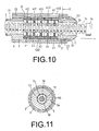
- the lock knob 5 is then rotated to align a predetermined number 51 with the positioning mark 26 on the lock mount 2, by which the fixing pin 55 of the lock knob 5 is ejected from the section of annular grooves 74 to the wide lateral face 72, forming an unlocked state.
- the retractable rod 7 therefore can be pulled from the lock mount 2 to have the hook member 31 of the retaining rod 3 to engage with the inner rim of a steering wheel.
- the hook member 71 of the retractable rod 7 is hooked at the inner rim of the steering wheel on the opposite side.
- the rotary blocks of the combination lock 4 in the lock mount 2 are then randomly turned to other angular positions, and therefore the eccentric holes 411, 421, 431, 441 and 451 are aligned no more.
- the ingrowing plates 410, 420, 430, 440 and 450 are engaged with the annular grooves 74 of the retractable rod 7, and the lock knob 5 is turned to another angular position so that the fixing pin 55 thereof is also engaged with a groove 74 of the retractable rod 7, completing the locking action.
- the double locking mechanisms by the combination lock 4 and the fixing pin 55 of the lock knob 5 presents a difficult task for a thief, because he or she has to decode the combination lock 4 and the lock knob 5 at the same time.
- a user may insert a long pin 80 and two short pins 81 and 82 into the pin holes 412, 422, 442 and 452, as shown in Figs. 3 and 5.
- the combination lock 4 is firstly adjusted to a predetermined set of pin codes, by which the pin holes 412, 422, 432, 442 and 452 are mutually aligned.
- the long pin 80 is inserted through the pin hole 52 of the lock knob 5 into the pin holes 412 and 422, and the rotary block 41 is rotated to drive the long pin 80 so the rotary block 42 is accordingly rotated.
- the rotary block 43 is then rotated so that the pin hole 432 is aligned with the pin holes 442 and 452 no more.
- Two short pins 81 and 82 are respectively inserted into the pin hole 442 of the rotary block 44 and the pin hole 452 of the rotary block 45.
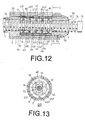
- the rotary blocks 44 and 45 are randomly rotated so that the pin holes therein are aligned no more, as shown in Figs. 12 and 13.
- the locking mechanism of the pin set 8 is thus completed.
- the design of the pin set 8 is to prolong the time a thief needs to decode the steering wheel lock, so that an automobile that has parked for a long time can be safe.
- the pin holes 412, 422, 432, 442 and 452 have to be mutually aligned.
- the aligned pin holes have to be aligned with the pin hole 52 of the lock knob 5 and the through hole 25 of the lock mount 2.
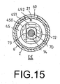
- An ejection pin 83 is then inserted into the through hole 25 of the lock mount 2 to eject the pin set 8 from the pin holes through the pin hole 52 of the lock knob 5, as shown in Figs.14 and 15.
- the aligned angular positions of the pin holes 412, 422, 432, 442, 452, the pin hole 52 of the lock knob 5 and the through hole 25 of the lock mount 2 must be known to withdraw the long pin 80 and two short pins 81 and 82.
- the ejection pin 83 can be inserted into the through hole 25 to push the long pin 80 in the pin holes 412 and 422 toward the rotary block 43.
- the rotary block 43 is distributed with a plurality of stepped false pin holes 433, the long pin 80 engaged with one of the false pin holes 433 moves a little along the hole and get blocked at the other end.
- the rotary blocks of the combination lock 4 are turned to predetermined angular positions, so that the pin holes 412, 422, 432, 442 and 452 are mutually aligned, and, further, the aligned pin holes are aligned with the pin hole 52 of the lock knob 5 and the 25 of the lock mount 2.
- An ejection pin 83 is then inserted into the through hole 25 of the lock mount 2 to eject the pin set 8 from the pin holes through the pin hole 52 of the lock knob 5, as shown in Figs.14 and 15.
- the rotary blocks can be rotated independently, so that they can be adjusted according to a predetermined open code, under which the eccentric holes 411, 421, 431, 441 and 451 are mutually aligned, as shown in Figs. 8 and 9.
- the numeric mark 51 of the lock knob 5 is then aligned with the positioning mark 26 of the lock mount 2 to have the fixing pin 55 of the lock knob 5 departed from an annular groove 74 the retractable rod 7 to the wide lateral face 72 thereof, as shown in Figs.10 and 11.
- the retractable rod 7 therefore can move backward into the lock mount 2 to complete the unlocking action.
- the ingrowing plates 410, 420, 430, 440 and 450 are provided with a rectangular eccentric holes 411, 412, 431, 441 and 451.
- the rod member 70 of the retractable rod 7 is also eccentric, having a wide lateral face 72 and a narrow lateral face 73 opposite to each other.
- the eccentricity of the eccentric holes 411-451 and the rod member 70 is to prevent a situation that a rotary block turns 180 degrees from the predetermined angular position and is still blocked by the ingrowing plates 410, 420, 430, 440 and 450.
- the present invention is advantageous in: (1) multiple locking mechanisms for attaining a better anti-theft effect; (2) no need for a key; (3) an additional pin set for prolonging the operation time of a thief.
Landscapes
- Engineering & Computer Science (AREA)
- Mechanical Engineering (AREA)
- Lock And Its Accessories (AREA)
Abstract
Description
- The present invention relates to steering wheel locks, and more particularly to a steering wheel lock comprising a lock mount, a retaining rod, a combination lock, a lock knob, a lock sleeve, a retractable rod and a pin set. Besides the double locking mechanisms of the combination lock and the lock knob, a pin set can be inserted into pin holes within the combination lock for an extra locking function, especially suitable for providing anti-theft measure for long-term parking.
- A steering wheel lock of the prior art, as shown in Fig.1, comprises a main body 1 underneath a
hook member 10 is attached. The main body 1 is further is provided a lock core on the top face thereof and ahandle 12 on a lateral side thereof. A throughhole 13 is formed on another side of the main body 1 for receiving aretractable rod 14. Theretractable rod 14 is provided with ahook member 15 at one end and a plurality ofengaging grooves 16. - To use the steering wheel lock, it is placed over a steering wheel, and the
hook member 10 is then engaged with the inner rim of the steering wheel. Theretractable rod 14 is pulled out from the main body 1 till thehook member 15 is also engaged with the inner rim of the wheel on the opposite side. The blocking arms of the main body 1 extend into the space between the steering wheel and the driver's seat so that the rotational range of the wheel is restricted, achieving an anti-theft effect. - However, the conventional steering wheel locks are vulnerable to strong striking force applied at the
retractable rod 14 and the main body 1 in the inward direction, which may causes the parts in the lock core to break, therefore losing the locking function. It is a further disadvantage that a key is necessary to unlock the lock. The user has to take extra efforts to keep the key. - Accordingly, the primary object of the present invention is to provide a steering wheel lock having multiple locking mechanisms. The steering wheel lock comprises a lock mount, a retaining rod, a combination lock, a lock knob, a lock sleeve, a retractable rod and a pin set. The double locking function provided by the combination lock and the lock knob makes decoding much more difficult. It is an additional locking mechanism that a pin set composed of a long pin and two short pins can be inserted into the pin holes within the combination lock. An extra code set specifying the alignment configuration of the pin holes is then needed to open the lock.
- More specifically, the lock mount is provided with a receptacle and a window. A first pin hole for receiving a retaining pin is further provided at an open first end of the lock mount. A first through hole connecting the receptacle is formed at a closed second end of the lock mount. A mark is formed on an outer lateral wall of the lock mount at the open first end. The retaining rod substantially mounted on the second end of the lock mount, which consists of a first rod member and a first hook member. A second through hole is coaxially formed within the rod member. The combination lock mounted within the lock mount is composed of a plurality of rotary blocks, each of the rotary blocks being provided with an ingrowing plate having a third through hole whose center is slightly off the center of the corresponding rotary block. A set of numeric marks is formed around an outer round wall of each of the rotary blocks. The lock knob provided with a fourth through hole is mounted on the first end of the lock mount. A numeric mark set is provided on a lateral side of the lock knob about the fourth through hole. An annular groove is formed around an outer round wall of the lock knob. A second pin hole going into the fourth through hole for receiving a fixing pin is formed on the outer round wall of the lock knob. A retractable rod going through the lock mount into the retaining rod consists of a second rod member and a second hook member. The second rod member has a wide lateral face and a narrow lateral face and therefore a non-symmetrical cross-section. The second rod member being further provided with a plurality of annular grooves.
- The various objects and advantages of the present invention will be more readily understood from the following detailed description when read in conjunction with the appended drawings.
-
- Fig. 1 is an exploded perspective view of a conventional steering wheel lock.
- Fig. 2 is an exploded perspective view of the present invention.
- Fig. 3 is a perspective view of the present invention.
- Fig. 4 is a cross-sectional view of the retractable rod of the present invention locked in the lock mount.
- Fig. 5 is a cross-sectional view showing the interior of the lock mount.
- Fig.6 is a cross-section view of the lock mount along the A-A cut line according to Fig.5.
- Fig.7 is a cross-section view of the lock mount along the B-B cut line according to Fig.5.
- Fig.8 is a cross-sectional view of the present invention wherein the rotary blocks are aligned whereas the lock knob is not.
- Fig.9 is a cross-section view of the lock mount along the C-C cut line according to Fig.8.
- Fig.10 is a cross-sectional view of the present invention wherein both the rotary blocks and the lock knob are aligned.
- Fig.11 is a cross-section view of the lock mount along the D-D cut line according to Fig.10.
- Fig.12 is a cross-section view showing a long pin and two short pins being inserted into the pin holes in the rotary blocks.
- Fig.13 is a cross-section view of the lock mount along the E-E cut line according to Fig.12.
- Fig.14 illustrates the pin holes on the rotary blocks being aligned and the ejection pin is inserted to eject the long pin and short pins.
- Fig.15 is a cross-section view of the lock mount along the F-F cut line according to Fig.14.
-
- Referring to Figs. 2, 3, 4 and 5, the present invention comprises a
lock mount 2, aretaining rod 3, acombination lock 4, alock knob 5, alock sleeve 6, aretractable rod 7 and apin set 8. - The
lock mount 2 is substantially cylindrical, having an open first end and a closed second end that contains a throughhole 24; thethrough hole 24 is coaxial with the axis of thelock mount 2. The interior portion of thelock mount 2 defines areceptacle 20. Awindow 21 is formed on the lateral round wall of thelock mount 2. The lateral wall of thelock mount 2 is further provided with athrough hole 22 for receiving aretaining pin 23 and amark 26, both locating at the first end of thelock mount 2 and roughly 90 degrees apart. The lateral wall of thelock mount 2 is further provided with athrough hole 25, locating at the second end of thelock mount 2. - The
retaining rod 3, composed of arod member 30 and ahook member 31, is substantially mounted on the second end of thelock mount 2. Therod member 30 is a hollow cylinder, the interior portion of which defines a throughhole 32. - The
combination lock 4, composed of afirst rotary block 41, a secondrotary block 42, a thirdrotary block 43, a fourthrotary block 44 and a fifthrotary block 45, is mounted within thereceptacle 20 of thelock mount 2. Each of the rotary blocks contains an ingrowing plate, which can be 410, 420, 430, 440 or 450. Each of the ingrowing plates is provided with a rectangular eccentric hole, which can be 411, 421, 431, 441 or 451. A lateral side of each of the rotary blocks is provided with a pin hole, which can be 412, 422, 432, 442 or 452. On the same lateral sides where the pin holes are located, the firstrotary block 41 and the secondrotary block 42 are further provided with false pin holes 413 and 423 respectively. The thirdrotary block 43 is provided with a plurality of false pin holes 433, circling around a lateral side thereof. A set of numeric marks, which can be 414, 424, 434, 444 or 454, is formed on the outer round wall of each of the rotary blocks. - The
lock knob 5, substantially a cylindrical body, is mounted on the first end of thelock mount 2. Thelock knob 5 has a coaxial throughhole 50. On a lateral side of thelock knob 5 around the throughhole 50, a numeric mark set 51 is provided. Apin hole 52 is formed on the numeric mark set 51, which goes through the lateral side wall of thelock knob 5. The outer round wall of thelock knob 5 is further provided with anannular groove 53 and a throughhole 54 going into the throughhole 50 for receiving a fixingpin 55. - The
lock sleeve 6 encloses thelock mount 2 and is provided with fivewindows 60 on the lateral wall thereof. Thewindows 60 are longitudinally located according to the locations of the inner rotary blocks and transversely interlaced. - The
retractable rod 7, composed of arod member 70 and ahook member 71, is capable of being inserted through thelock mount 2 into the retainingrod 3. Therod member 70 takes a rectangular cross-section and therefore has a widelateral face 72 and a narrowlateral face 73. Therod member 70 is further provided with a plurality ofannular grooves 74. Apin hole 75 is formed at the end of theretractable rod 7 far from thehook member 71 for receiving a blockingpin 76. - The pin set 8 is composed of a
long pin 80, twoshort pins ejection pin 83. The pin set 8 is for going through the pin holes 412, 422, 432, 442 and 452 of thecombination lock 4. - Refer to Figs. 2, 3, and 4 for the assembly of a steering wheel lock according to the present invention. Firstly, the rotary blocks of the
combination lock 4 are orderly placed into thereceptacle 20 within thelock mount 2. Thelock knob 5 is then mounted onto the open first end of thelock mount 2 by inserting the retainingpin 23 through the throughhole 22 of thelock mount 2 into theannular groove 53 around thelock knob 5. Thelock knob 5 is thus rotatably held at the first end of thelock mount 2. Thelock sleeve 6 is put on thelock mount 2 to enclose the shell, and theretractable rod 7 is inserted through the throughhole 50 of thelock knob 5, theeccentric holes lock mount 2, and the throughhole 24 of thelock mount 2; the blockingpin 76 is then inserted into thepin hole 75 of theretractable rod 7 for retaining theretractable rod 7 in thelock mount 2. The retainingrod 3 is fixedly connected with the throughhole 24 on thelock mount 2, so that theretractable rod 7 extends into the throughhole 32 of the retainingrod 3. The steering wheel lock is thereby assembled. - Refer to Figs. 5, 6 and 7 for using the steering wheel lock. The
lock sleeve 6 is firstly rotated so as to subsequently align thewindows 60 with the rotary blocks exposed in thewindow 21 on thelock mount 2. Each of the rotary blocks 41 to 45 is turned to have the respective open code to appear in therespective window 60. Theeccentric holes 411 to 451 in this rotary block configuration are mutually aligned, as shown in Figs. 8 and 9. Thelock knob 5 is then rotated to align apredetermined number 51 with thepositioning mark 26 on thelock mount 2, by which the fixingpin 55 of thelock knob 5 is ejected from the section ofannular grooves 74 to the widelateral face 72, forming an unlocked state. Theretractable rod 7 therefore can be pulled from thelock mount 2 to have thehook member 31 of the retainingrod 3 to engage with the inner rim of a steering wheel. Thehook member 71 of theretractable rod 7 is hooked at the inner rim of the steering wheel on the opposite side. The rotary blocks of thecombination lock 4 in thelock mount 2 are then randomly turned to other angular positions, and therefore theeccentric holes ingrowing plates annular grooves 74 of theretractable rod 7, and thelock knob 5 is turned to another angular position so that the fixingpin 55 thereof is also engaged with agroove 74 of theretractable rod 7, completing the locking action. The double locking mechanisms by thecombination lock 4 and the fixingpin 55 of thelock knob 5 presents a difficult task for a thief, because he or she has to decode thecombination lock 4 and thelock knob 5 at the same time. - For an even better anti-theft function, a user may insert a
long pin 80 and twoshort pins combination lock 4 is firstly adjusted to a predetermined set of pin codes, by which the pin holes 412, 422, 432, 442 and 452 are mutually aligned. Thelong pin 80 is inserted through thepin hole 52 of thelock knob 5 into the pin holes 412 and 422, and therotary block 41 is rotated to drive thelong pin 80 so therotary block 42 is accordingly rotated. Therotary block 43 is then rotated so that thepin hole 432 is aligned with the pin holes 442 and 452 no more. Twoshort pins pin hole 442 of therotary block 44 and thepin hole 452 of therotary block 45. The rotary blocks 44 and 45 are randomly rotated so that the pin holes therein are aligned no more, as shown in Figs. 12 and 13. The locking mechanism of the pin set 8 is thus completed. The design of the pin set 8 is to prolong the time a thief needs to decode the steering wheel lock, so that an automobile that has parked for a long time can be safe. To open the steering wheel lock having thelong pin 80 and twoshort pins 81and 82 inside, the pin holes 412, 422, 432, 442 and 452 have to be mutually aligned. And, further, the aligned pin holes have to be aligned with thepin hole 52 of thelock knob 5 and the throughhole 25 of thelock mount 2. Anejection pin 83 is then inserted into the throughhole 25 of thelock mount 2 to eject the pin set 8 from the pin holes through thepin hole 52 of thelock knob 5, as shown in Figs.14 and 15. The aligned angular positions of the pin holes 412, 422, 432, 442, 452, thepin hole 52 of thelock knob 5 and the throughhole 25 of thelock mount 2 must be known to withdraw thelong pin 80 and twoshort pins hole 25 and the pin holes 412 and 422, theejection pin 83 can be inserted into the throughhole 25 to push thelong pin 80 in the pin holes 412 and 422 toward therotary block 43. However, since therotary block 43 is distributed with a plurality of stepped false pin holes 433, thelong pin 80 engaged with one of the false pin holes 433 moves a little along the hole and get blocked at the other end. Without knowing thelong pin 80 being trapped in afalse pin hole 433, the thief continues to rotate therotary block 43, and the insertion of thelong pin 80 into therotary block 43 drives the rotary blocks 41 and 42 together, prohibiting separate rotation of the rotary blocks and therefore not being able to align thoseeccentric holes - To unlock the steering wheel lock, the rotary blocks of the
combination lock 4 are turned to predetermined angular positions, so that the pin holes 412, 422, 432, 442 and 452 are mutually aligned, and, further, the aligned pin holes are aligned with thepin hole 52 of thelock knob 5 and the 25 of thelock mount 2. Anejection pin 83 is then inserted into the throughhole 25 of thelock mount 2 to eject the pin set 8 from the pin holes through thepin hole 52 of thelock knob 5, as shown in Figs.14 and 15. After that, the rotary blocks can be rotated independently, so that they can be adjusted according to a predetermined open code, under which theeccentric holes numeric mark 51 of thelock knob 5 is then aligned with thepositioning mark 26 of thelock mount 2 to have the fixingpin 55 of thelock knob 5 departed from anannular groove 74 theretractable rod 7 to the widelateral face 72 thereof, as shown in Figs.10 and 11. Theretractable rod 7 therefore can move backward into thelock mount 2 to complete the unlocking action. Theingrowing plates eccentric holes rod member 70 of theretractable rod 7 is also eccentric, having a widelateral face 72 and a narrowlateral face 73 opposite to each other. The eccentricity of the eccentric holes 411-451 and therod member 70 is to prevent a situation that a rotary block turns 180 degrees from the predetermined angular position and is still blocked by theingrowing plates - According to the preferred embodiments, the present invention is advantageous in: (1) multiple locking mechanisms for attaining a better anti-theft effect; (2) no need for a key; (3) an additional pin set for prolonging the operation time of a thief.
- The present invention is thus described, and it will be obvious that the same may be varied in many ways. Such variations are not to be regarded as a departure from the spirit and scope of the present invention, and all such modifications as would be obvious to one skilled in the art are intended to be included within the scope of the following claims.
Claims (4)
- A steering wheel lock comprising:a lock mount provided with a receptacle and a window, a first pin hole for receiving a retaining pin being further provided at an open first end of the lock mount, a first through hole connecting the receptacle being formed at a closed second end of the lock mount, a mark being formed on an outer lateral wall of the lock mount at the open first end;a retaining rod substantially mounted on the second end of the lock mount, the retaining rod consisting of a first rod member and a first hook member, a second through hole being formed within the rod member;a combination lock mounted within the lock mount being composed of a plurality of rotary blocks, each of the rotary blocks being provided with an ingrowing plate having a third through hole whose center is slightly off the center of the corresponding rotary block, a set of numeric marks being formed around an outer round wall of each of the rotary blocks;a lock knob provided with a fourth through hole being mounted on the first end of the lock mount, a numeric mark set being provided on a lateral side of the lock knob about the fourth through hole, an annular groove being formed around an outer round wall of the lock knob, a second pin hole going into the fourth through hole for receiving a fixing pin being formed on the outer round wall of the lock knob; and,a retractable rod going through the lock mount into the retaining rod consisting of a second rod member and a second hook member, the second rod member having a wide lateral face and a narrow lateral face and therefore a non-symmetrical cross-section, the second rod member being further provided with a plurality of annular grooves.
- The steering wheel lock according to claim 1, wherein a side wall of the lock mount is provided with an rejection pin hole; a side wall of the lock knob is provided with a first through pin hole; a second through pin hole is provided to each of the rotary blocks of the combination lock; a false pin hole is provided to each of the first rotary block and the second rotary block; a plurality of stepped false pin holes are formed around a side wall of third rotary block; a pin set comprising a long pin, two short pins and rejection pin is capable of being inserted though the through pin holes within the rotary blocks.
- The steering wheel lock according to claim 1, wherein the lock mount is enclosed by a lock sleeve, on which a plurality of windows for viewing numeric marks of the rotary blocks are arranged in an interlaced pattern.
- The steering wheel lock according to claim 1, wherein an end of the second rod member of the retractable rod is provided with a pin hole for receiving a blocking pin; the blocking pin is for preventing the retractable rod from the lock mount.
Priority Applications (1)
| Application Number | Priority Date | Filing Date | Title |
|---|---|---|---|
| EP03027408A EP1535812A1 (en) | 2003-11-27 | 2003-11-27 | Steering wheel lock |
Applications Claiming Priority (1)
| Application Number | Priority Date | Filing Date | Title |
|---|---|---|---|
| EP03027408A EP1535812A1 (en) | 2003-11-27 | 2003-11-27 | Steering wheel lock |
Publications (1)
| Publication Number | Publication Date |
|---|---|
| EP1535812A1 true EP1535812A1 (en) | 2005-06-01 |
Family
ID=34442902
Family Applications (1)
| Application Number | Title | Priority Date | Filing Date |
|---|---|---|---|
| EP03027408A Withdrawn EP1535812A1 (en) | 2003-11-27 | 2003-11-27 | Steering wheel lock |
Country Status (1)
| Country | Link |
|---|---|
| EP (1) | EP1535812A1 (en) |
Cited By (1)
| Publication number | Priority date | Publication date | Assignee | Title |
|---|---|---|---|---|
| CN102995970A (en) * | 2012-12-31 | 2013-03-27 | 刘从杰 | Novel mechanical coded lock and key thereof |
Citations (5)
| Publication number | Priority date | Publication date | Assignee | Title |
|---|---|---|---|---|
| DE2710444A1 (en) * | 1977-03-10 | 1978-09-14 | Gustav Joo | Anti-theft device for car - has hooked clamp with combination lock extending between steering wheel and pedal |
| ES2134684A1 (en) * | 1995-11-08 | 1999-10-01 | Quero Vicente Navarro | High-security anti-theft device, without a key, for vehicles |
| US5970758A (en) * | 1998-11-13 | 1999-10-26 | Chan Hau Enterprise Co., Ltd. | Automobile steering lock |
| US20010032485A1 (en) * | 1988-12-20 | 2001-10-25 | Winner International Royalty Llc | Steering wheel lock |
| WO2003006281A1 (en) * | 2001-07-13 | 2003-01-23 | Jakov Vukovic | The universal blocking system used for the prevention of car break-ins |
-
2003
- 2003-11-27 EP EP03027408A patent/EP1535812A1/en not_active Withdrawn
Patent Citations (5)
| Publication number | Priority date | Publication date | Assignee | Title |
|---|---|---|---|---|
| DE2710444A1 (en) * | 1977-03-10 | 1978-09-14 | Gustav Joo | Anti-theft device for car - has hooked clamp with combination lock extending between steering wheel and pedal |
| US20010032485A1 (en) * | 1988-12-20 | 2001-10-25 | Winner International Royalty Llc | Steering wheel lock |
| ES2134684A1 (en) * | 1995-11-08 | 1999-10-01 | Quero Vicente Navarro | High-security anti-theft device, without a key, for vehicles |
| US5970758A (en) * | 1998-11-13 | 1999-10-26 | Chan Hau Enterprise Co., Ltd. | Automobile steering lock |
| WO2003006281A1 (en) * | 2001-07-13 | 2003-01-23 | Jakov Vukovic | The universal blocking system used for the prevention of car break-ins |
Cited By (1)
| Publication number | Priority date | Publication date | Assignee | Title |
|---|---|---|---|---|
| CN102995970A (en) * | 2012-12-31 | 2013-03-27 | 刘从杰 | Novel mechanical coded lock and key thereof |
Similar Documents
| Publication | Publication Date | Title |
|---|---|---|
| US6755063B2 (en) | Side bar type cylinder lock with variable key code | |
| US6862905B2 (en) | Pin locking device and method of locking | |
| US7174756B2 (en) | Padlock | |
| EP1003949B1 (en) | Electromechanical cylinder lock with rotary release | |
| US6389857B1 (en) | Push-button steering wheel lock | |
| US5720191A (en) | Padlock | |
| US4083211A (en) | Axial split-pin tumbler-type lock mechanism for a handle lock | |
| IE86904B1 (en) | Lock cylinder | |
| US6634197B2 (en) | Lock device with removable core | |
| US6453706B1 (en) | Padlock with a U-shaped lock casing | |
| US5400624A (en) | U-shaped padlock structure | |
| US6263711B1 (en) | Cable lock | |
| US6817215B1 (en) | Steering wheel lock | |
| JP4353848B2 (en) | Cylinder lock | |
| US6698264B1 (en) | Core assembly for a lock | |
| CA2254353C (en) | Lock with improved torsional strength | |
| EP1535812A1 (en) | Steering wheel lock | |
| US20060000248A1 (en) | Cylinder lock | |
| US6176110B1 (en) | Vehicle steering wheel locking device | |
| US5709115A (en) | Sidebar ignition lock | |
| JPH08120982A (en) | Cylinder lock | |
| JP3074077U (en) | Double pin tumbler type locking device | |
| JP2002256736A (en) | Cylinder lock device | |
| JP2556632Y2 (en) | Locking device | |
| JPH0448296Y2 (en) |
Legal Events
| Date | Code | Title | Description |
|---|---|---|---|
| PUAI | Public reference made under article 153(3) epc to a published international application that has entered the european phase |
Free format text: ORIGINAL CODE: 0009012 |
|
| 17P | Request for examination filed |
Effective date: 20040714 |
|
| AK | Designated contracting states |
Kind code of ref document: A1 Designated state(s): AT BE BG CH CY CZ DE DK EE ES FI FR GB GR HU IE IT LI LU MC NL PT RO SE SI SK TR |
|
| AX | Request for extension of the european patent |
Extension state: AL LT LV MK |
|
| GRAP | Despatch of communication of intention to grant a patent |
Free format text: ORIGINAL CODE: EPIDOSNIGR1 |
|
| AKX | Designation fees paid |
Designated state(s): AT BE BG CH CY CZ DE DK EE ES FI FR GB GR HU IE IT LI LU MC NL PT RO SE SI SK TR |
|
| STAA | Information on the status of an ep patent application or granted ep patent |
Free format text: STATUS: THE APPLICATION IS DEEMED TO BE WITHDRAWN |
|
| 18D | Application deemed to be withdrawn |
Effective date: 20051110 |