EP1535764A1 - Tubeless tire - Google Patents
Tubeless tire Download PDFInfo
- Publication number
- EP1535764A1 EP1535764A1 EP03712897A EP03712897A EP1535764A1 EP 1535764 A1 EP1535764 A1 EP 1535764A1 EP 03712897 A EP03712897 A EP 03712897A EP 03712897 A EP03712897 A EP 03712897A EP 1535764 A1 EP1535764 A1 EP 1535764A1
- Authority
- EP
- European Patent Office
- Prior art keywords
- layer
- sealant
- tire
- agent
- tubeless tire
- Prior art date
- Legal status (The legal status is an assumption and is not a legal conclusion. Google has not performed a legal analysis and makes no representation as to the accuracy of the status listed.)
- Withdrawn
Links
Images


Classifications
-
- B—PERFORMING OPERATIONS; TRANSPORTING
- B60—VEHICLES IN GENERAL
- B60C—VEHICLE TYRES; TYRE INFLATION; TYRE CHANGING; CONNECTING VALVES TO INFLATABLE ELASTIC BODIES IN GENERAL; DEVICES OR ARRANGEMENTS RELATED TO TYRES
- B60C19/00—Tyre parts or constructions not otherwise provided for
- B60C19/12—Puncture preventing arrangements
- B60C19/122—Puncture preventing arrangements disposed inside of the inner liner
-
- B—PERFORMING OPERATIONS; TRANSPORTING
- B29—WORKING OF PLASTICS; WORKING OF SUBSTANCES IN A PLASTIC STATE IN GENERAL
- B29C—SHAPING OR JOINING OF PLASTICS; SHAPING OF MATERIAL IN A PLASTIC STATE, NOT OTHERWISE PROVIDED FOR; AFTER-TREATMENT OF THE SHAPED PRODUCTS, e.g. REPAIRING
- B29C73/00—Repairing of articles made from plastics or substances in a plastic state, e.g. of articles shaped or produced by using techniques covered by this subclass or subclass B29D
- B29C73/16—Auto-repairing or self-sealing arrangements or agents
- B29C73/18—Auto-repairing or self-sealing arrangements or agents the article material itself being self-sealing, e.g. by compression
- B29C73/20—Auto-repairing or self-sealing arrangements or agents the article material itself being self-sealing, e.g. by compression the article material only consisting in part of a deformable sealing material
-
- B—PERFORMING OPERATIONS; TRANSPORTING
- B29—WORKING OF PLASTICS; WORKING OF SUBSTANCES IN A PLASTIC STATE IN GENERAL
- B29D—PRODUCING PARTICULAR ARTICLES FROM PLASTICS OR FROM SUBSTANCES IN A PLASTIC STATE
- B29D30/00—Producing pneumatic or solid tyres or parts thereof
- B29D30/06—Pneumatic tyres or parts thereof (e.g. produced by casting, moulding, compression moulding, injection moulding, centrifugal casting)
- B29D30/0681—Parts of pneumatic tyres; accessories, auxiliary operations
- B29D30/0685—Incorporating auto-repairing or self-sealing arrangements or agents on or into tyres
- B29D2030/0686—Incorporating sealants on or into tyres not otherwise provided for; auxiliary operations therefore, e.g. preparation of the tyre
- B29D2030/0689—Incorporating sealants on or into tyres not otherwise provided for; auxiliary operations therefore, e.g. preparation of the tyre by incorporating the sealant into a plurality of chambers, e.g. bags, cells, tubes or closed cavities
-
- B—PERFORMING OPERATIONS; TRANSPORTING
- B29—WORKING OF PLASTICS; WORKING OF SUBSTANCES IN A PLASTIC STATE IN GENERAL
- B29D—PRODUCING PARTICULAR ARTICLES FROM PLASTICS OR FROM SUBSTANCES IN A PLASTIC STATE
- B29D30/00—Producing pneumatic or solid tyres or parts thereof
- B29D30/06—Pneumatic tyres or parts thereof (e.g. produced by casting, moulding, compression moulding, injection moulding, centrifugal casting)
- B29D30/0681—Parts of pneumatic tyres; accessories, auxiliary operations
- B29D30/0685—Incorporating auto-repairing or self-sealing arrangements or agents on or into tyres
- B29D2030/0686—Incorporating sealants on or into tyres not otherwise provided for; auxiliary operations therefore, e.g. preparation of the tyre
- B29D2030/0695—Incorporating sealants on or into tyres not otherwise provided for; auxiliary operations therefore, e.g. preparation of the tyre the sealant being in the form of one wide strip, e.g. a patch
-
- B—PERFORMING OPERATIONS; TRANSPORTING
- B29—WORKING OF PLASTICS; WORKING OF SUBSTANCES IN A PLASTIC STATE IN GENERAL
- B29L—INDEXING SCHEME ASSOCIATED WITH SUBCLASS B29C, RELATING TO PARTICULAR ARTICLES
- B29L2030/00—Pneumatic or solid tyres or parts thereof
-
- Y—GENERAL TAGGING OF NEW TECHNOLOGICAL DEVELOPMENTS; GENERAL TAGGING OF CROSS-SECTIONAL TECHNOLOGIES SPANNING OVER SEVERAL SECTIONS OF THE IPC; TECHNICAL SUBJECTS COVERED BY FORMER USPC CROSS-REFERENCE ART COLLECTIONS [XRACs] AND DIGESTS
- Y10—TECHNICAL SUBJECTS COVERED BY FORMER USPC
- Y10T—TECHNICAL SUBJECTS COVERED BY FORMER US CLASSIFICATION
- Y10T152/00—Resilient tires and wheels
- Y10T152/10—Tires, resilient
- Y10T152/10495—Pneumatic tire or inner tube
- Y10T152/10666—Automatic sealing of punctures [e.g., self-healing, etc.]
- Y10T152/10675—Using flowable coating or composition
- Y10T152/10684—On inner surface of tubeless tire
- Y10T152/10693—Sealant in plural layers or plural pockets
Definitions
- This invention relates to a tubeless tire preventing air leakage from a tire by a sealant agent provided in an inside, even if the tire receives external damage by treading a nail, etc., during traveling.
- a tubeless tire (referred to as a "sealant tire” henceforth), inside of which is applied with sealant agent consisting of adhesive rubber etc. is known. Even if this sealant tire receives external damage by treading a nail, etc., outflow of air can be controlled completely by a self-sealing property of the sealant agent of burying a hole by flowing into the external damage part. And this sealant agent is formed in a certain amount of (4mm or more) thickness for obtaining sufficient self-sealing property, and the viscosity is set to somewhat low.
- the viscosity of the sealant agent is made low in order to obtain a self-sealing property, there is a possibility of the deviation of the sealant agent, due to its flowability when subjected to vibration accompanying rotation of the tire during traveling.
- the deviation of the sealant agent is the causative factor of generating vibration during traveling due to unbalance of a tire.
- the viscosity of the sealant agent is made high, sufficient self-sealing property cannot be obtained and it becomes a factor of an air leakage.
- the sealant agent when the viscosity of the sealant agent is made high, when the foreign substance that is irregular on the surfaces, such as a wood screw, is stuck on a tire, the sealant agent does not adhere to the surface of the foreign substance enough. On the other hand, if the viscosity of the sealant agent is made low, the foreign substance shakes by vibration accompanying the rotation of the tire, involving the possibility that the sealant agent exfoliated from the foreign substance by this shaking, and further the hole formed with the foreign substance is expanded.
- the object of this invention is to provide a tubeless tire satisfying a sufficient self-sealing property even when the amount of applications of a sealant agent is lessened for mainly reducing the weight of a tire.
- another object of this invention is to provide a tubeless tire that can prevent vibration of vehicles due to the deviation of the sealant agent by controlling a flow of the sealant agent with low viscosity during traveling.
- a cover layer formed of a seat that adheres firmly to the inside of the sealant layer and having permeability is provided in a tubeless tire which is provided inside of a keeping air-tightness layer that keeps the inside of a tire airtightly.
- a “keeping air-tightness layer” means a layer that keeps the inside of a tire airtightly, and generally means an inner liner layer provided in an innermost part of a tire.
- this belt layer or the like is also included.
- materials, rubber, resin and these compounds, and the materials combined by reinforcing materials are further listed as these layers.
- the sealant agent that moves so that it may be drawn in the hole opened by the nail etc, adheres firmly to inner side of the keeping air-tightness layer and the surface of the cover layer, to thereby receive adhesive resistance that works in the reverse direction with respect to the move direction. Also, in order to obtain self-sealing property of the sealant agent, even when the viscosity is made low, flow of the sealant agent is suppressed by the above-described adhesive resistance.
- the cover layer and the sealant layer rubber composite are laminated in order on a forming machine first.
- the inner liner layer serving as a keeping air-tightness layer, for example is laminated, and henceforth formation is performed according to a forming method of the usual tubeless tire.
- the reinforcing agent that can adjust the viscosity to the sealant agent freely is mixed in the tubeless tire of this invention.
- the viscosity of the sealant agent (flowability) is adjusted by adjusting the amount of the reinforcing agent to be mixed in the sealant agent.
- this invention provides a tubeless tire in which pluralities of compound layers consisting of the sealant layer formed of the sealant agent and the cover layers that adhere to the inside of the sealant layers are provided inside of the keeping air-tightness layer that keeps inside of the tire airtightly, wherein the cover layer in the compound layers of at least innermost layer has permeability.
- the tubeless tire of such composition for example, even when the cover layer of the first sheet receives external damage by foreign substances, such as a nail, the damaged part of the cover layer is buried by the sealant layer provided in the inner side.
- sealant agent is preferably divided at least in either direction of the width direction or the circumferential direction of a tire.
- Fig.1 is a major structure of a tubeless tire of this invention by enlarged sectional view
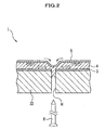
- Fig.2 is a major structure showing a sealant layer and the action of a cover layer at the time of escaping from a nail from a tire.
- tubeless tire 1 has outer layer part 2 and inner liner layer (keeping air-tightness layer) 3 consisting of rubber or the like which is adhered to the whole inner surface of the outer layer part 2. Furthermore, this tubeless tire 1 includes sealant layer 4 that adheres firmly to the inside of the inner liner layer 3, and the cover layer 5 that adheres firmly to the inside of this sealant layer 4.
- the outer layer part 2 has bead part 21 that anchors a tubeless tire to Wheel W, tread part 22 that touches the ground, and sidewall part 23 which is a region between the bead part 21 and the tread parts 22. Also, inside the bead part 21, the tread part 22, and the sidewall part 23, carcass 24 consisting of fiber material for maintaining the form of tubeless tire 1 is formed. And between the tread part 22 and the carcass 24, two or more belt layers 25 for providing the rigidity of the tread part 22 are provided.
- the inner liner layer 3 has the function to keep the inside of the tubeless tire 1 airtightly, and prevents the air charged into the inside of the tubeless tire 1 from leaking outside. And this inner liner layer 3 adheres to the whole inner surface of the outer layer part 2.
- the sealant layer 4 is formed in substantially the same width with the width of the tread part 22.
- the sealant agent which forms this sealant layer 4 is formed by heating the sheet-like rubber composite mainly containing butyl rubber, and peroxide, etc.
- the reinforcing agent capable of adjusting the viscosity of the sealant agent freely is mixed in the sealant layer rubber composite serving as the sealant agent.
- Short fiber for reinforcing obtained by cutting a fiber material such as nylon and polyester generally used for a tire in length of 1 mm to 10 mm can be used.
- this reinforcing material is not limited to the short fiber, but a carbon fiber, or a fiberglass, etc. may be adopted.
- the sheet in the profile of cloth such as nylon or polyester etc, woven as having an extension property, or in the profile of mesh may be stacked one upon another.
- the cover layer 5 is formed with the sheet consisting of rubber having the permeability of natural rubber etc.
- permeability means the excellence in permeability capable of penetrating inside of a tire by the gas generated when chemical reaction is induced by the sealant layer rubber composite.
- the cover layer 5 is formed with the width of somewhat larger than the width of the sealant layer 4, and set to the thickness within the range of about 0.5mm to 5mm.
- this cover layer 5 can be suitably changed in consideration of a property of cover layer material, the physical properties of the sealant agent and thickness. However, in order to reduce the weight of a tire, it is preferable to form in thinner thickness.
- the cover layer 5 is made of rubber. However, as long as the permeability of this invention is exerted, any material can be used.
- the sealant layer rubber material made of butadiene rubber as the main composite element, a non-woven fabric, resin, or these compounds, etc. may be used as cover materials.
- the cover layer 5 and the sealant layer rubber composite used as the sealant layer 4 are laminated on the forming machine, not shown, orderly. Subsequently, inner liner layer 3 is laminated and henceforth formation is performed according to a forming method of the usual tubeless tire.
- inner liner layer 3 is laminated and henceforth formation is performed according to a forming method of the usual tubeless tire.
- the butyl rubber contained in the sealant layer rubber composite is depolymerized by peroxide and heat, and thus the sealant layer rubber composite changes into an adhesive sealant agent.
- the gas generated by the chemical reaction of the sealant layer rubber composite is discharged inside the tire through the cover layer 5 that has permeability.
- the sealant layer 4 and the cover layer 5 firmly adheres.
- the sealant agent may be applied onto the inner liner layer 3, and the cover layer 5 may be laminated thereon.
- the tire according to the present invention can be manufactured by adding a required process to the product line, which is used for manufacturing the conventional tire, therefore it is preferable to manufacture by the manufacture method of this embodiment.
- the tubeless tire 1' according to the second embodiment includes the sealant layer 4 firmly adhering to the inner side (inside) of the cover layer 5 of the tubeless tire 1 according to the first embodiment, and the cover layer 5 adhering to the inner side of the sealant layer 4.
- the tubeless tire 1' has dual structure of the first sealing layers (compound layers) S1 consisting of the sealant layer 4 adhering firmly to the inner liner layer 3 and the cover layer 5, and the second sealing layers (compound layers) S2 consisting of the sealant layer 4 adhering to the first sealing layer S1 and the cover layer 5.
- tubeless tire 1" is arranged in such a way that the sealant layer 4 of the first embodiment and the cover layer 5 are divided. That is, the first sealing layers S1 consisting of the sealant layer 4 and the cover layer 5 are formed with the first to fifth division sealing layers S11 to S15 arranged orderly toward another side from one side of the width direction of the tubeless tire 1".
- the first division sealing layers S11 consist of the first sealant layer 41 and the first cover layer 51, and adhere firmly to the portion ranging from the sidewall part 23 in the inner liner layer 3 to the tread part 22.
- the second sealing layers S12 consist of the second sealant layer 42 and the second cover layer 52. Partition wall part 52a that divides the sealant layer 41 of the above first and the second sealant layer 42 in the width direction of the tubeless tire 1" is formed in one edge of this second cover layer 52.
- the third to fifth division sealing layers S13 to S15 are formed substantially in the same way as the second division sealing layers S12.
- the second and third sealant layers 42 and 43 are divided by partition wall part 53a of the third cover layer 53.
- the third and fourth sealant layers 43 and 44 are divided by partition wall part 54a of the fourth cover layer 54.
- the fourth and fifth sealant layers 44 and 45 are divided by the partition wall part 55a of the fifth cover layer 55.
Landscapes
- Engineering & Computer Science (AREA)
- Mechanical Engineering (AREA)
- Tires In General (AREA)
Abstract
Description
Claims (4)
- A tubeless tire comprising: a sealant layer formed of a sealant agent adheres firmly to inside of a keeping air-tightness layer that keeps the inside of said tubeless tire airtightly; and a cover layer formed of a sheet adhering firmly to the inside of said sealant layer and having permeability.
- A tubeless tire as described in claim 1, wherein said sealant agent contains a reinforcing agent that adjusts its viscosity.
- A tubeless tire, comprising pluralities of compound layers consisting of a sealant layer formed of a sealant agent and a cover layer that adheres firmly to the inside of the sealant layer inside the keeping air-tightness layer that keeps the inside of the tire airtightly, wherein the cover layer in the compound layers of at least innermost layer has permeability.
- A tubeless tire as described in claim 1, wherein the sealant agent is divided at least in either direction of the width direction or the circumferential direction of a tire.
Applications Claiming Priority (3)
| Application Number | Priority Date | Filing Date | Title |
|---|---|---|---|
| JP2002082375A JP3996796B2 (en) | 2002-03-25 | 2002-03-25 | Tubeless tire |
| JP2002082375 | 2002-03-25 | ||
| PCT/JP2003/003586 WO2003080370A1 (en) | 2002-03-25 | 2003-03-25 | Tubeless tire |
Publications (2)
| Publication Number | Publication Date |
|---|---|
| EP1535764A1 true EP1535764A1 (en) | 2005-06-01 |
| EP1535764A4 EP1535764A4 (en) | 2010-04-14 |
Family
ID=28449142
Family Applications (1)
| Application Number | Title | Priority Date | Filing Date |
|---|---|---|---|
| EP03712897A Withdrawn EP1535764A4 (en) | 2002-03-25 | 2003-03-25 | Tubeless tire |
Country Status (4)
| Country | Link |
|---|---|
| US (1) | US20040149366A1 (en) |
| EP (1) | EP1535764A4 (en) |
| JP (1) | JP3996796B2 (en) |
| WO (1) | WO2003080370A1 (en) |
Families Citing this family (25)
| Publication number | Priority date | Publication date | Assignee | Title |
|---|---|---|---|---|
| FR2874616B1 (en) * | 2004-08-31 | 2007-06-01 | Ruiz Maria Amelia Ramon | HOMOGENEOUS CHEMICAL RANGE OF HIGH VISCOSITY ANTI-CUP FLUID AND ITS VARIANTS, FORMING AN ADDITIONAL REINFORCING LAYER ON THE TREAD BAND AND ON THE FLANKS OF TIRES |
| JP4559265B2 (en) * | 2005-03-11 | 2010-10-06 | 横浜ゴム株式会社 | Pneumatic tire and manufacturing method thereof |
| US20080156408A1 (en) * | 2005-03-11 | 2008-07-03 | The Yokohama Rubber Co., Ltd. | Pneumatic Tire and Method of Manufacturing the Same |
| JP4491564B2 (en) * | 2005-10-24 | 2010-06-30 | 横浜ゴム株式会社 | Pneumatic tire |
| US20080142140A1 (en) * | 2006-12-15 | 2008-06-19 | Patrick David Marks | Method and apparatus for building a puncture sealant tire |
| CN101778715A (en) * | 2007-07-24 | 2010-07-14 | 横滨橡胶株式会社 | Process for producing self-sealing pneumatic tire and apparatus therefor |
| US8617333B2 (en) | 2007-09-20 | 2013-12-31 | The Goodyear Tire & Rubber Company | Pneumatic tire having built-in sealant layer and preparation thereof |
| US20090078353A1 (en) * | 2007-09-21 | 2009-03-26 | Ramendra Nath Majumdar | Pneumatic Tire Having Built-In Sealant Layer And Preparation Thereof |
| US8316903B2 (en) * | 2007-10-01 | 2012-11-27 | The Goodyear Tire & Rubber Company | Pneumatic tire having built-in sealant layer and preparation thereof |
| JP2009269446A (en) * | 2008-05-07 | 2009-11-19 | Yokohama Rubber Co Ltd:The | Pneumatic tire and method of manufacturing the same |
| JP4569666B2 (en) * | 2008-05-13 | 2010-10-27 | 横浜ゴム株式会社 | Pneumatic tire |
| US20100154959A1 (en) | 2008-12-23 | 2010-06-24 | Ramendra Nath Majumdar | Method and apparatus for building a tire having a puncture sealant |
| IT1396617B1 (en) * | 2009-11-25 | 2012-12-14 | Pirelli | METHOD FOR SELF-CHECKING THE SELF-SEALING CAPACITY OF A SELF-SEALING PNEUMATIC AND TIRE FOR VEHICLE WHEELS |
| US8387672B2 (en) * | 2010-03-18 | 2013-03-05 | The Goodyear Tire & Rubber Company | Pneumatic tire with built-in sealant layer composite |
| US8646501B2 (en) | 2010-11-11 | 2014-02-11 | The Goodyear Tire & Rubber Company | Puncture sealant laminate |
| KR101497839B1 (en) * | 2013-11-12 | 2015-03-02 | 한국타이어 주식회사 | Pneumatic tire with multiple layer sealant structure |
| US9421824B2 (en) * | 2014-04-29 | 2016-08-23 | The Goodyear Tire & Rubber Company | Pneumatic tire with sealant layer |
| US11738606B2 (en) * | 2014-12-16 | 2023-08-29 | Triangle Tyre Co. Ltd. | Multilayer intrinsic sealants based on ionic butyl |
| US10399391B2 (en) * | 2014-12-16 | 2019-09-03 | Triangle Tyre Co., Ltd. | Pneumatic tire having multiple built-in sealant layers and preparation thereof |
| EP3541609B1 (en) * | 2016-11-17 | 2022-06-15 | Bridgestone Americas Tire Operations, LLC | Pneumatic tire having a sealant layer and air barrier layer |
| JP2019018800A (en) * | 2017-07-20 | 2019-02-07 | 住友ゴム工業株式会社 | Pneumatic tire and method for manufacturing the same |
| IT201800006010A1 (en) * | 2018-06-04 | 2019-12-04 | SEALANT LAYER OF A TIRE | |
| DE102019207493A1 (en) * | 2019-05-22 | 2020-11-26 | Continental Reifen Deutschland Gmbh | Pneumatic vehicle tires with a sealant layer |
| CN110920326A (en) * | 2019-12-29 | 2020-03-27 | 江苏通用科技股份有限公司 | A puncture-proof tire structure |
| JP7670950B2 (en) * | 2020-09-25 | 2025-05-01 | 横浜ゴム株式会社 | Pneumatic tires |
Family Cites Families (21)
| Publication number | Priority date | Publication date | Assignee | Title |
|---|---|---|---|---|
| US2877819A (en) * | 1953-03-03 | 1959-03-17 | Seiberling Rubber Co | Puncture sealing pneumatic tire |
| US3048509A (en) * | 1959-12-22 | 1962-08-07 | Gen Tire & Rubber Co | Puncture sealing means for pneumatic tires |
| JPS5025683B1 (en) * | 1970-07-28 | 1975-08-26 | ||
| CA987211A (en) * | 1973-05-03 | 1976-04-13 | Roy J. Emerson | Puncture sealing means for pneumatic tires |
| US4171237A (en) * | 1975-09-22 | 1979-10-16 | The Firestone Tire & Rubber Company | Sealant laminates |
| JPS5936675B2 (en) * | 1975-10-16 | 1984-09-05 | 株式会社ブリヂストン | Tire puncture self-closing layer |
| JPS5273401A (en) * | 1975-12-11 | 1977-06-20 | Sumitomo Rubber Ind | Pneumatic tire with adhesive puncture sealing layer |
| JPS52148602U (en) * | 1976-05-07 | 1977-11-11 | ||
| GB1559939A (en) * | 1976-08-20 | 1980-01-30 | Firestone Tire & Rubber Co | Sealant laminates |
| JPS5480905A (en) * | 1977-12-12 | 1979-06-28 | Yokohama Rubber Co Ltd:The | Composition of sealant used for preventing puncture of type |
| FR2425335A1 (en) * | 1978-05-10 | 1979-12-07 | Michelin & Cie | PNEUMATIC CONTAINING A GASKET OF PERFORATION CLOSURE |
| FR2431380A1 (en) * | 1978-07-17 | 1980-02-15 | Michelin & Cie | PNEUMATIC TIRE WITH SHUTTER COVER |
| US4228839A (en) | 1978-08-03 | 1980-10-21 | The Firestone Tire & Rubber Company | Self-sealing pneumatic tire |
| US4426468A (en) * | 1978-10-10 | 1984-01-17 | Rockcor, Inc. | Sealant composition |
| US4895610A (en) | 1983-08-15 | 1990-01-23 | The Goodyear Tire & Rubber Company | Self-sealing pneumatic tire and method of manufacturing the same |
| US4664168A (en) * | 1985-01-22 | 1987-05-12 | The Uniroyal Goodrich Tire Company | Self-sealing tire with edge strips for tire sealant |
| US5576373A (en) * | 1993-04-05 | 1996-11-19 | Exxon Chemical Patents Inc. | Composite tire innerliners and inner tubes |
| JP4255156B2 (en) * | 1999-02-26 | 2009-04-15 | 住友ゴム工業株式会社 | Pneumatic tire and method for manufacturing pneumatic tire |
| US6112790A (en) * | 1999-03-17 | 2000-09-05 | Taiwan Kings Glory Co., Ltd. | Puncture-durable tire structure |
| JP2002059722A (en) * | 2000-08-11 | 2002-02-26 | Bridgestone Corp | Safety pneumatic tire and safety tube for pneumatic tire |
| JP2003080909A (en) * | 2001-09-14 | 2003-03-19 | Yokohama Rubber Co Ltd:The | Pneumatic tire and method of manufacturing the same |
-
2002
- 2002-03-25 JP JP2002082375A patent/JP3996796B2/en not_active Expired - Fee Related
-
2003
- 2003-03-25 EP EP03712897A patent/EP1535764A4/en not_active Withdrawn
- 2003-03-25 US US10/450,057 patent/US20040149366A1/en not_active Abandoned
- 2003-03-25 WO PCT/JP2003/003586 patent/WO2003080370A1/en not_active Ceased
Also Published As
| Publication number | Publication date |
|---|---|
| JP3996796B2 (en) | 2007-10-24 |
| JP2003276409A (en) | 2003-09-30 |
| EP1535764A4 (en) | 2010-04-14 |
| US20040149366A1 (en) | 2004-08-05 |
| WO2003080370A1 (en) | 2003-10-02 |
Similar Documents
| Publication | Publication Date | Title |
|---|---|---|
| EP1535764A1 (en) | Tubeless tire | |
| US7717146B2 (en) | Pneumatic tire and noise damper assembly | |
| CN100355593C (en) | Pneumatic tire with noise damper | |
| US20170015146A1 (en) | Pneumatic vehicle tire | |
| CA2368005C (en) | A puncture resistant pneumatic tire | |
| EP3490818B1 (en) | Pneumatic tyre | |
| US11794530B2 (en) | Tire with intrinsic sealant containing intrinsic cellular innermost layer | |
| JP4297241B2 (en) | Pneumatic tire | |
| JPH08323875A (en) | Method for manufacturing tire with seal liquid layer | |
| EP1484199A1 (en) | Self seal tire and its producing method | |
| WO2022171162A1 (en) | Tire with intrinsic sealant containing intrinsic cellular innermost layer | |
| US20020036042A1 (en) | Pneumatic tire | |
| JPH11216781A (en) | Pneumatic tire and method for manufacturing pneumatic tire | |
| JP4615764B2 (en) | Pneumatic tire | |
| JP2000177307A (en) | Tubeless tire | |
| WO2022171161A1 (en) | Tires with intrinsic cellular noise damper | |
| JP4456189B2 (en) | Pneumatic tire and method for manufacturing pneumatic tire | |
| JPH03124430A (en) | Tire |
Legal Events
| Date | Code | Title | Description |
|---|---|---|---|
| PUAI | Public reference made under article 153(3) epc to a published international application that has entered the european phase |
Free format text: ORIGINAL CODE: 0009012 |
|
| 17P | Request for examination filed |
Effective date: 20030526 |
|
| AK | Designated contracting states |
Kind code of ref document: A1 Designated state(s): AT BE BG CH CY CZ DE DK EE ES FI FR GB GR HU IE IT LI LU MC NL PT RO SE SI SK TR |
|
| RBV | Designated contracting states (corrected) |
Designated state(s): DE FR GB |
|
| A4 | Supplementary search report drawn up and despatched |
Effective date: 20100316 |
|
| RIC1 | Information provided on ipc code assigned before grant |
Ipc: B60C 19/12 20060101AFI20050414BHEP Ipc: B29C 73/22 20060101ALI20100310BHEP Ipc: B29L 30/00 20060101ALI20100310BHEP |
|
| 17Q | First examination report despatched |
Effective date: 20100630 |
|
| STAA | Information on the status of an ep patent application or granted ep patent |
Free format text: STATUS: THE APPLICATION HAS BEEN WITHDRAWN |
|
| 18W | Application withdrawn |
Effective date: 20120309 |