EP1535681A1 - Tool for chip-removing machining - Google Patents
Tool for chip-removing machining Download PDFInfo
- Publication number
- EP1535681A1 EP1535681A1 EP04445119A EP04445119A EP1535681A1 EP 1535681 A1 EP1535681 A1 EP 1535681A1 EP 04445119 A EP04445119 A EP 04445119A EP 04445119 A EP04445119 A EP 04445119A EP 1535681 A1 EP1535681 A1 EP 1535681A1
- Authority
- EP
- European Patent Office
- Prior art keywords
- insert
- cutting insert
- protrusions
- seat
- holder
- Prior art date
- Legal status (The legal status is an assumption and is not a legal conclusion. Google has not performed a legal analysis and makes no representation as to the accuracy of the status listed.)
- Granted
Links
- 238000003754 machining Methods 0.000 title claims abstract description 18
- 230000006978 adaptation Effects 0.000 description 1
- 230000008878 coupling Effects 0.000 description 1
- 238000010168 coupling process Methods 0.000 description 1
- 238000005859 coupling reaction Methods 0.000 description 1
- 230000001419 dependent effect Effects 0.000 description 1
- 238000006073 displacement reaction Methods 0.000 description 1
- 230000002349 favourable effect Effects 0.000 description 1
- 238000012986 modification Methods 0.000 description 1
- 230000004048 modification Effects 0.000 description 1
Images




Classifications
-
- B—PERFORMING OPERATIONS; TRANSPORTING
- B23—MACHINE TOOLS; METAL-WORKING NOT OTHERWISE PROVIDED FOR
- B23B—TURNING; BORING
- B23B27/00—Tools for turning or boring machines; Tools of a similar kind in general; Accessories therefor
- B23B27/14—Cutting tools of which the bits or tips or cutting inserts are of special material
- B23B27/16—Cutting tools of which the bits or tips or cutting inserts are of special material with exchangeable cutting bits or cutting inserts, e.g. able to be clamped
-
- B—PERFORMING OPERATIONS; TRANSPORTING
- B23—MACHINE TOOLS; METAL-WORKING NOT OTHERWISE PROVIDED FOR
- B23B—TURNING; BORING
- B23B27/00—Tools for turning or boring machines; Tools of a similar kind in general; Accessories therefor
- B23B27/14—Cutting tools of which the bits or tips or cutting inserts are of special material
- B23B27/141—Specially shaped plate-like cutting inserts, i.e. length greater or equal to width, width greater than or equal to thickness
- B23B27/145—Specially shaped plate-like cutting inserts, i.e. length greater or equal to width, width greater than or equal to thickness characterised by having a special shape
-
- B—PERFORMING OPERATIONS; TRANSPORTING
- B23—MACHINE TOOLS; METAL-WORKING NOT OTHERWISE PROVIDED FOR
- B23B—TURNING; BORING
- B23B27/00—Tools for turning or boring machines; Tools of a similar kind in general; Accessories therefor
- B23B27/14—Cutting tools of which the bits or tips or cutting inserts are of special material
- B23B27/16—Cutting tools of which the bits or tips or cutting inserts are of special material with exchangeable cutting bits or cutting inserts, e.g. able to be clamped
- B23B27/1603—Cutting tools of which the bits or tips or cutting inserts are of special material with exchangeable cutting bits or cutting inserts, e.g. able to be clamped with specially shaped plate-like exchangeable cutting inserts, e.g. chip-breaking groove
- B23B27/1611—Cutting tools of which the bits or tips or cutting inserts are of special material with exchangeable cutting bits or cutting inserts, e.g. able to be clamped with specially shaped plate-like exchangeable cutting inserts, e.g. chip-breaking groove characterised by having a special shape
-
- B—PERFORMING OPERATIONS; TRANSPORTING
- B23—MACHINE TOOLS; METAL-WORKING NOT OTHERWISE PROVIDED FOR
- B23B—TURNING; BORING
- B23B29/00—Holders for non-rotary cutting tools; Boring bars or boring heads; Accessories for tool holders
-
- B—PERFORMING OPERATIONS; TRANSPORTING
- B23—MACHINE TOOLS; METAL-WORKING NOT OTHERWISE PROVIDED FOR
- B23B—TURNING; BORING
- B23B2200/00—Details of cutting inserts
- B23B2200/16—Supporting or bottom surfaces
- B23B2200/165—Supporting or bottom surfaces with one or more grooves
-
- B—PERFORMING OPERATIONS; TRANSPORTING
- B23—MACHINE TOOLS; METAL-WORKING NOT OTHERWISE PROVIDED FOR
- B23B—TURNING; BORING
- B23B2205/00—Fixation of cutting inserts in holders
- B23B2205/12—Seats for cutting inserts
-
- Y—GENERAL TAGGING OF NEW TECHNOLOGICAL DEVELOPMENTS; GENERAL TAGGING OF CROSS-SECTIONAL TECHNOLOGIES SPANNING OVER SEVERAL SECTIONS OF THE IPC; TECHNICAL SUBJECTS COVERED BY FORMER USPC CROSS-REFERENCE ART COLLECTIONS [XRACs] AND DIGESTS
- Y10—TECHNICAL SUBJECTS COVERED BY FORMER USPC
- Y10T—TECHNICAL SUBJECTS COVERED BY FORMER US CLASSIFICATION
- Y10T407/00—Cutters, for shaping
- Y10T407/22—Cutters, for shaping including holder having seat for inserted tool
- Y10T407/227—Cutters, for shaping including holder having seat for inserted tool with separate means to fasten tool seat to holder
-
- Y—GENERAL TAGGING OF NEW TECHNOLOGICAL DEVELOPMENTS; GENERAL TAGGING OF CROSS-SECTIONAL TECHNOLOGIES SPANNING OVER SEVERAL SECTIONS OF THE IPC; TECHNICAL SUBJECTS COVERED BY FORMER USPC CROSS-REFERENCE ART COLLECTIONS [XRACs] AND DIGESTS
- Y10—TECHNICAL SUBJECTS COVERED BY FORMER USPC
- Y10T—TECHNICAL SUBJECTS COVERED BY FORMER US CLASSIFICATION
- Y10T407/00—Cutters, for shaping
- Y10T407/22—Cutters, for shaping including holder having seat for inserted tool
- Y10T407/2272—Cutters, for shaping including holder having seat for inserted tool with separate means to fasten tool to holder
-
- Y—GENERAL TAGGING OF NEW TECHNOLOGICAL DEVELOPMENTS; GENERAL TAGGING OF CROSS-SECTIONAL TECHNOLOGIES SPANNING OVER SEVERAL SECTIONS OF THE IPC; TECHNICAL SUBJECTS COVERED BY FORMER USPC CROSS-REFERENCE ART COLLECTIONS [XRACs] AND DIGESTS
- Y10—TECHNICAL SUBJECTS COVERED BY FORMER USPC
- Y10T—TECHNICAL SUBJECTS COVERED BY FORMER US CLASSIFICATION
- Y10T407/00—Cutters, for shaping
- Y10T407/22—Cutters, for shaping including holder having seat for inserted tool
- Y10T407/2272—Cutters, for shaping including holder having seat for inserted tool with separate means to fasten tool to holder
- Y10T407/2274—Apertured tool
-
- Y—GENERAL TAGGING OF NEW TECHNOLOGICAL DEVELOPMENTS; GENERAL TAGGING OF CROSS-SECTIONAL TECHNOLOGIES SPANNING OVER SEVERAL SECTIONS OF THE IPC; TECHNICAL SUBJECTS COVERED BY FORMER USPC CROSS-REFERENCE ART COLLECTIONS [XRACs] AND DIGESTS
- Y10—TECHNICAL SUBJECTS COVERED BY FORMER USPC
- Y10T—TECHNICAL SUBJECTS COVERED BY FORMER US CLASSIFICATION
- Y10T407/00—Cutters, for shaping
- Y10T407/22—Cutters, for shaping including holder having seat for inserted tool
- Y10T407/2272—Cutters, for shaping including holder having seat for inserted tool with separate means to fasten tool to holder
- Y10T407/2282—Cutters, for shaping including holder having seat for inserted tool with separate means to fasten tool to holder including tool holding clamp and clamp actuator
-
- Y—GENERAL TAGGING OF NEW TECHNOLOGICAL DEVELOPMENTS; GENERAL TAGGING OF CROSS-SECTIONAL TECHNOLOGIES SPANNING OVER SEVERAL SECTIONS OF THE IPC; TECHNICAL SUBJECTS COVERED BY FORMER USPC CROSS-REFERENCE ART COLLECTIONS [XRACs] AND DIGESTS
- Y10—TECHNICAL SUBJECTS COVERED BY FORMER USPC
- Y10T—TECHNICAL SUBJECTS COVERED BY FORMER US CLASSIFICATION
- Y10T407/00—Cutters, for shaping
- Y10T407/23—Cutters, for shaping including tool having plural alternatively usable cutting edges
Definitions
- the present invention relates to a tool for chip-removing machining, the tool comprising an insert holder, a cutting insert for chip-removing machining, the cutting insert being indexable and turnable, as well as means for fixing the cutting insert in an insert seat of the insert holder.
- a tool for chip-removing machining according to the above-mentioned preamble is previously known from SE-A-0201573-3.
- the cutting insert is provided with a protruding male part, which is intended to co-operate with flexible portions of a female part in the insert seat.
- the cutting insert has a male part on the bottom side thereof, the cutting insert is not turnable.
- a tool coupling is previously known from WO 01/87523 A1, whereby a tool for chip-removing machining according to the preamble defined above is previously known through an embodiment described in this document.
- a cutting insert for chip-removing machining included in the tool is previously known and an insert holder included in the tool is previously known.
- the cutting insert for chip-removing machining has on the bottom side thereof a male part and the insert holder has a female part corresponding to the male part.
- the male part comprises a number of teeth having both axial and radial extensions.
- the female part comprises a number of recesses, which are designed to receive the teeth of the male part.
- both the male part and the female part may be conical.
- a primary object of the present invention is to provide a tool of the kind defined above, as well as the cutting insert included in the tool and the insert holder included in the tool, whereby the fixation of the cutting insert in the insert holder should be extraordinarily stable at the same time as the cutting insert is turnable.
- the cutting insert can withstand forces which are changeable and acting from different directions and that the fixation is not materially affected by shifting temperatures that may occur during true working conditions.
- Another object of the present invention is to use such materials in the insert holder and the cutting insert that the properties of the materials are optimally utilized.
- the tool comprises an insert holder 1, a cutting insert 3 for chip-removing machining and means for fixation, in the form of a locking screw 5, in order to fix the cutting insert 3 in an insert seat 7 of the insert holder 1.
- the locking screw 5 has a conical head 6.
- a common centre axis for the locking screw 5, the cutting insert 3 and the insert seat 7 is designated C-C in Fig 1.
- the cutting insert 3 for chip-removing machining has two base surfaces 4, only one of which is visible in Fig 2.
- the base surfaces 4 are parallel with each other.
- the cutting insert 3 also has a through-going first centre hole 2 for receipt of the locking screw 5.
- the cutting insert 3 is provided with four recesses 9 in the base surface 4 thereof as can be seen in Fig 2.
- Each one of the recesses 9 generally has the shape of a piece of a cake.
- the four recesses 9 are identical.
- first protrusions 10 are formed, which also are four in number.
- the first protrusions 10 are identical.
- Each one of the recesses 9 is defined by a first, curved circumferential surface 11, which constitutes the part of the recesses 9 that is situated farthest away from the centre of the cutting insert 3.
- Each one of the recesses 9 is further defined by a bottom surface 12, which is generally parallel with the base surface 4 of the cutting insert 3.
- Each one of the recesses 9 is further defined by two side surfaces 13, which generally have a radial extension toward the centre axis C-C of the cutting insert 3.
- Each one of the first protrusions 10 defines a generally rectangular surface 15, which constitutes a part surface of one base surface 4 of the cutting insert 3. Furthermore, each one of the first protrusions 10 defines a front surface 16 facing the centre of the cutting insert 3, which front surface generally slopes away from the centre of the cutting insert 3 in the direction toward one adjacent base surface 4 of the cutting insert 3.
- the side surfaces 13 included in the recesses 9 are common to the recesses 9 and the first protrusions 10, i.e., the side surfaces 13 constitute bordering surfaces also to the first protrusions 10. If the two side surfaces 13 that belong to one and the same first protrusion 10 are regarded, these two side surfaces 13 converge slightly toward each other in the direction toward the adjacent base surface 4 of the cutting insert 3.
- the cutting insert 3 is indexable, i.e., it may be brought to assume four different positions when one and the same base surface 4 abuts against the insert seat 7.
- the cutting insert 3 is of a negative basic shape and it has a second base surface, which is hidden in Fig 2. Said second base surface has an identical design as the shown base surface 4 regarding the recesses 9 and the first protrusions 10. This means that the cutting insert 3, in addition to being indexable, furthermore is turnable, i.e., both the base surfaces 4 may be brought to abutment against the insert seat 7 of the insert holder 1.
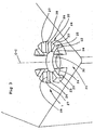
- the insert seat 7 shown in detail in Fig 3 comprises a number of second protrusions 20, which generally project from an abutment surface 21 of the insert holder 1.
- the second protrusions 20 generally have the shape of "pieces of a cake" and taper in the direction inwards towards the centre axis C-C of the insert seat 7.
- Each one of the second protrusions 20 is provided with a slot 22, which has an axial extension along a greater part of the height of the second protrusion 20 and a radial extension along the entire radial extension of the second protrusion 20.
- the slot 22 divides the second protrusion 20 into two equally great parts. The function of the slot 22 will be described below.
- Each one of the second protrusions 20 is defined by a second, curved circumferential surface 23, which constitutes the part of the second protrusions 20 that is situated farthest away from the centre axis C-C of the insert seat 7.
- the second, curved circumferential surface 23 is intersected by the appurtenant slot 22.
- Each one of the second protrusions 20 is also defined by two upper surfaces 24, which generally are of a triangular shape and are parallel with the abutment surface 21 of the insert seat 7.
- Each one of the second protrusions 20 is also defined by two internal side surfaces 25, which generally are planar and located in the slot 22.
- Each one of the second protrusions 20 is also defined by two external first and second part side surfaces 26 and 27, said part side surfaces 26 and 27 being spaced apart by a dividing line 28, which extends parallel with the abutment surface 21 of the insert seat 7.
- the first part side surfaces 26 have an extension perpendicular to the abutment surface 21 while the second part side surfaces 27 slightly converge towards each other in the direction toward the upper surfaces 24 of the second protrusions 20.
- the insert seat 7 is also provided with an internally threaded second hole 30, which is intended to receive the externally threaded portion of the locking screw 5.
- the second protrusions 20 of the insert seat 7 are brought to be received in the recesses 9 of the cutting insert 3.
- the second part surfaces 27 of the second protrusions 20 will come to abutment against the side surfaces 13 of the cutting insert 3. Therefore, it is suitable that the second part surfaces 27 and the side surfaces 13 have a corresponding inclination in relation to a common reference plane. This means that the second part surfaces 27 and the side surfaces 13 should be parallel with each other when the cutting insert 3 is mounted on the insert holder 1.
- a base surface 4 of the cutting insert 3 abuts against the abutment surface 21 of the insert seat 7.
- an abutment also takes place between the second part surfaces 27 of the second protrusions 20 and the side surfaces 13 of the cutting insert 3.
- the second protrusions 20 will apply counterdirected forces to the two side surfaces 13 of a first protrusion 10 of the cutting insert 3, which generate compressive stresses in the first protrusions 10 of the cutting insert 3. This is exceptionally important when the cutting insert 3, and thereby also the first protrusions 10, are made from cemented carbide or similar hard materials that generally cannot carry tensile stresses.
- each second protrusion 20 ensures that the second protrusion 20 is imparted certain flexibility, i.e., that the part protrusions included in a second protrusion can be mutually displaced somewhat in relation to each other in connection with the cutting insert 3 being mounted on the insert holder 1.
- the mutual displacement of the part protrusions against each other thereby generally takes place in a direction that is parallel with the abutment surface 21 of the insert seat 7.
- This flexibility of the second protrusions 20 ensures that a substantially satisfactory abutment is obtained between the side surfaces 13 and the second part side surfaces 27. Thereby, an extraordinarily stable clamping of the cutting insert 3 on the insert holder 1 is obtained.
- the insert seat 107 comprises four second protrusions 120, which are identical and arranged symmetrically around an internally threaded second centre hole 130 of the insert seat 107.
- Each one of the second protrusions 120 is defined by a second, curved circumferential surface 123, which constitutes the part of the second protrusions 120 that is situated farthest away from the centre axis C-C of the insert seat 107.
- Each one of the second protrusions 120 is also defined by an upper surface 124, which is of a generally triangular shape and parallel with the abutment surface 121 of the insert seat 107.
- Each one of the second protrusions 120 is also defined by two external side surfaces 127, which generally have a radial extension. The side surfaces 127 slightly converge towards each other in the direction toward the upper surface 124 of the second protrusions 120.
- each one of the second protrusions 120 is provided with notches (undercuts) 122 in the area of connection between the second protrusions 120 and the abutment surface 121 and more precisely in the area of the connection of the side surfaces 127 to the abutment surface 121 of the insert seat 107, i.e., each second protrusion 120 has two notches 122.
- the arrangement of the notches 122 impart the second protrusions 120 certain flexibility, whereby a marginal downward deflection of the protrusions 120 is enabled adjacent to the side surfaces 127.
- the deflection generally takes place in a direction that is perpendicular to the abutment surface 121 of the insert seat 107.
- the flexibility is favourable as for the co-operation of the side surfaces 127 with the associated surfaces of the cutting insert (not shown) that shall be clamped in the insert seat 107.
- the cutting insert not shown has, correspondingly to the cutting insert 3 above, recesses and first protrusions, which are formed for an optimum co-operation with the second protrusions 120.
- FIG 5 a second alternative embodiment of an insert seat 207 of an insert holder 201 included in a tool according to the present invention is shown.
- the insert seat 207 comprises four second protrusions 220, which are identical and arranged symmetrically around an internally threaded centre hole 230 of the insert seat 207.
- Each one of the second protrusions 220 is defined by a second, curved circumferential surface 223, which constitutes the part of the second protrusions 220 that is situated farthest away from the centre axis C-C of the insert seat 207.
- Each one of the second protrusions 220 is also defined by an upper surface 224, which is of a generally triangular shape and parallel with the abutment surface 221 of the insert seat 207.
- Each one of the second protrusions 220 is also defined by two external first and second part side surfaces 226 and 227, said part side surfaces 226 and 227 being spaced apart by a dividing line 228 that extends parallel with the abutment surface 221 of the insert seat 207.
- the first part side surfaces 226 have an extension perpendicular to the abutment surface 221 while the second part side surfaces 227 slightly converge towards each other in the direction toward the upper surface 224 of the second protrusions 220.
- the parts of the second protrusions 220 located closest to the centre axis C-C of the insert seat 207 extend a distance into the centre hole 230.
- each one of the second protrusions 220 does not have any subjacent support, which ensures that the second protrusions 220 get certain flexibility.
- a marginal downward deflection of the parts of the second protrusions 220 located closest to the centre axis C-C is allowed, the deflection generally taking place in a direction perpendicular to the abutment surface 221 of the insert seat 207.
- the significance of the same flexibility especially applies to the co-operation of the second part side surfaces 227 with the recesses and the first protrusions of a cutting insert (not shown) that is intended to be received in the insert seat 207.
- the tool comprises an insert holder 301, a cutting insert 303 for chip-removing machining and fixing means, in the form of a locking screw 305, for fixing the cutting insert 303 in an insert seat 307 of the insert holder 301.
- the locking screw 305 has a conical head 306.
- a common centre axis for the locking screw 305, the cutting insert 303 and the insert seat 307 is designated C-C in Fig 1.
- the principal difference in comparison to the tool according to Fig 1 is that the cutting insert 303 is of a triangular basic shape and that the insert seat 301 is formed for adaptation to the same triangular basic shape.
- the recesses 309 of the cutting insert 303 are three in number and are defined by a plurality of side surfaces. Generally, the recesses 309 have a somewhat widening shape in the direction toward an adjacent base surface 304 of the cutting insert 303. Between the recesses 309, first protrusions 310 are formed.
- the insert seat according to Fig 6 comprises three second protrusions 320, which have a design that principally resembles the second protrusions 120 in Fig 4, especially concerning the fact that the second protrusions 320 have notches 322 that correspond to the notches 122 of the second protrusions 120.
- the second protrusions 320 are defined by a plurality of side surfaces and the second protrusions 320 generally have a somewhat tapering shape in the direction from an abutment surface 321 of the insert seat 307.
- the notches 322 impart certain flexibility to the second protrusions 320, said flexibility aiding co-operation with the recesses 309 of the cutting insert 303.
- the cutting insert 3; 303 is provided with a number of recesses 9; 309.
- said recesses may have a variety of different designs, the denomination female parts has been used in some of the appended claims.
- the insert seat 7; 107; 207; 307 is provided with a number of second protrusions 20; 120; 220; 320.
- said second protrusions may have a variety of different designs, the denomination male parts has been used in some of the appended claims.
- the cutting insert 3; 303 is fixed by means of a locking screw 5; 305 that extends through a centre hole 2; 302 of the cutting insert 3; 303.
- the cutting insert is fixed at the holder in an alternative way, wherein with an exemplifying and not limiting purpose, a top clamp may be mentioned.
- the tool comprises cutting inserts that generally are intended for external turning, the cutting edges of the cutting insert 3; 303 generally having an extension parallel to the abutment surface 21; 321 of the insert seat 7; 307.
- the insert holder carries a cutting insert for internal turning, whereby in such a case the cutting edge generally has an extension transverse to the abutment surface of the insert seat.
- the recesses 9; 309 of the cutting insert 3; 303 are mutually identical as well as that the second protrusions 20; 120; 220; 320 of the insert holder 1; 101; 201; 301 are mutually identical.
- the recesses and the second protrusions need not be identical within the scope of the present invention. If, for instance, a so-called copying insert (copyturning insert) is concerned that only is indexable in two positions, only the diametrically arranged protrusions need to be identical.
- all second protrusions 20; 120; 220; 320 are provided with identical means that impart the second protrusions 20; 120; 220; 320 certain flexibility.
- all second protrusions included in an insert seat are provided with identical means to bring about flexibility of the second protrusions.
- one second protrusion may, for instance, be provided with a radial slot while another second protrusion is provided with notches adjacent to the abutment surface.
- the two other second protrusions may lack means that bring about flexibility.
- the bottom surface 12 is generally parallel with the base surface 4 of the cutting insert, and the upper surfaces 24; 124; 224 are generally parallel with the abutment surface 21; 121; 221; 321 of the insert seat 7; 107; 207; 307.
- said surfaces slope inwardly in a direction towards the centre axis C-C.
Landscapes
- Engineering & Computer Science (AREA)
- Mechanical Engineering (AREA)
- Cutting Tools, Boring Holders, And Turrets (AREA)
Abstract
Description
- The present invention relates to a tool for chip-removing machining, the tool comprising an insert holder, a cutting insert for chip-removing machining, the cutting insert being indexable and turnable, as well as means for fixing the cutting insert in an insert seat of the insert holder.
- A tool for chip-removing machining according to the above-mentioned preamble is previously known from SE-A-0201573-3. In this connection, on the bottom side thereof the cutting insert is provided with a protruding male part, which is intended to co-operate with flexible portions of a female part in the insert seat. By the fact that the cutting insert has a male part on the bottom side thereof, the cutting insert is not turnable.
- A tool coupling is previously known from WO 01/87523 A1, whereby a tool for chip-removing machining according to the preamble defined above is previously known through an embodiment described in this document. Thereby, also a cutting insert for chip-removing machining included in the tool is previously known and an insert holder included in the tool is previously known. The cutting insert for chip-removing machining has on the bottom side thereof a male part and the insert holder has a female part corresponding to the male part. The male part comprises a number of teeth having both axial and radial extensions. The female part comprises a number of recesses, which are designed to receive the teeth of the male part. In general, both the male part and the female part may be conical.
- A primary object of the present invention is to provide a tool of the kind defined above, as well as the cutting insert included in the tool and the insert holder included in the tool, whereby the fixation of the cutting insert in the insert holder should be extraordinarily stable at the same time as the cutting insert is turnable. In this connection, it is particularly important that the cutting insert can withstand forces which are changeable and acting from different directions and that the fixation is not materially affected by shifting temperatures that may occur during true working conditions.
- Another object of the present invention is to use such materials in the insert holder and the cutting insert that the properties of the materials are optimally utilized.
- At least the primary object of the present invention is realised by means of a tool of the kind defined above, which has obtained the features defined in the
independent claim 1. Other independent claims define the features of the cutting insert for chip-removing machining and the insert holder. Preferred embodiments of the tool, the cutting insert and the insert holder are defined in the dependent claims. - Below, a number of embodiments of the invention will be described, reference being made to the appended drawings, where:
- Fig 1
- shows an exploded view in perspective of a tool according to the present invention;
- Fig 2
- shows a perspective view obliquely from above of a cutting insert included in the tool according to the present invention;
- Fig 3
- shows in detail, in a perspective view obliquely from above, an insert seat of an insert holder included in the tool;
- Fig 4
- shows in detail, in a perspective view obliquely from above, an alternative insert seat of an insert holder included in the tool;
- Fig 5
- shows in detail, in a perspective view obliquely from above, an additional alternative insert seat of an insert holder included in the tool; and
- Fig 6
- shows an exploded view in perspective of an alternative embodiment of a tool according to the present invention.
- In Fig 1, an exploded view of a tool according to the present invention is shown. Thus, the tool comprises an
insert holder 1, a cutting insert 3 for chip-removing machining and means for fixation, in the form of alocking screw 5, in order to fix thecutting insert 3 in aninsert seat 7 of theinsert holder 1. Thelocking screw 5 has aconical head 6. A common centre axis for thelocking screw 5, thecutting insert 3 and theinsert seat 7 is designated C-C in Fig 1. - As may be most clearly seen in Fig 2, the cutting insert 3 for chip-removing machining has two base surfaces 4, only one of which is visible in Fig 2. The base surfaces 4 are parallel with each other. The
cutting insert 3 also has a through-goingfirst centre hole 2 for receipt of thelocking screw 5. Thecutting insert 3 is provided with fourrecesses 9 in the base surface 4 thereof as can be seen in Fig 2. Each one of therecesses 9 generally has the shape of a piece of a cake. The fourrecesses 9 are identical. Between therecesses 9,first protrusions 10 are formed, which also are four in number. Thefirst protrusions 10 are identical. - Each one of the
recesses 9 is defined by a first, curvedcircumferential surface 11, which constitutes the part of therecesses 9 that is situated farthest away from the centre of thecutting insert 3. Each one of therecesses 9 is further defined by abottom surface 12, which is generally parallel with the base surface 4 of thecutting insert 3. Each one of therecesses 9 is further defined by twoside surfaces 13, which generally have a radial extension toward the centre axis C-C of thecutting insert 3. - Each one of the
first protrusions 10 defines a generallyrectangular surface 15, which constitutes a part surface of one base surface 4 of thecutting insert 3. Furthermore, each one of thefirst protrusions 10 defines afront surface 16 facing the centre of thecutting insert 3, which front surface generally slopes away from the centre of thecutting insert 3 in the direction toward one adjacent base surface 4 of thecutting insert 3. Theside surfaces 13 included in therecesses 9 are common to therecesses 9 and thefirst protrusions 10, i.e., theside surfaces 13 constitute bordering surfaces also to thefirst protrusions 10. If the twoside surfaces 13 that belong to one and the samefirst protrusion 10 are regarded, these twoside surfaces 13 converge slightly toward each other in the direction toward the adjacent base surface 4 of thecutting insert 3. By the fact that both therecesses 9 and thefirst protrusions 10 are identical, thecutting insert 3 is indexable, i.e., it may be brought to assume four different positions when one and the same base surface 4 abuts against theinsert seat 7. - The
cutting insert 3 is of a negative basic shape and it has a second base surface, which is hidden in Fig 2. Said second base surface has an identical design as the shown base surface 4 regarding therecesses 9 and thefirst protrusions 10. This means that thecutting insert 3, in addition to being indexable, furthermore is turnable, i.e., both the base surfaces 4 may be brought to abutment against theinsert seat 7 of theinsert holder 1. - The
insert seat 7 shown in detail in Fig 3 comprises a number ofsecond protrusions 20, which generally project from anabutment surface 21 of theinsert holder 1. Thesecond protrusions 20 generally have the shape of "pieces of a cake" and taper in the direction inwards towards the centre axis C-C of theinsert seat 7. Each one of thesecond protrusions 20 is provided with aslot 22, which has an axial extension along a greater part of the height of thesecond protrusion 20 and a radial extension along the entire radial extension of thesecond protrusion 20. Theslot 22 divides thesecond protrusion 20 into two equally great parts. The function of theslot 22 will be described below. - Each one of the
second protrusions 20 is defined by a second, curvedcircumferential surface 23, which constitutes the part of thesecond protrusions 20 that is situated farthest away from the centre axis C-C of theinsert seat 7. The second, curvedcircumferential surface 23 is intersected by theappurtenant slot 22. Each one of thesecond protrusions 20 is also defined by twoupper surfaces 24, which generally are of a triangular shape and are parallel with theabutment surface 21 of theinsert seat 7. Each one of thesecond protrusions 20 is also defined by two internal side surfaces 25, which generally are planar and located in theslot 22. Each one of thesecond protrusions 20 is also defined by two external first and second part side surfaces 26 and 27, said part side surfaces 26 and 27 being spaced apart by adividing line 28, which extends parallel with theabutment surface 21 of theinsert seat 7. The first part side surfaces 26 have an extension perpendicular to theabutment surface 21 while the second part side surfaces 27 slightly converge towards each other in the direction toward theupper surfaces 24 of thesecond protrusions 20. - The
insert seat 7 is also provided with an internally threadedsecond hole 30, which is intended to receive the externally threaded portion of the lockingscrew 5. - Upon mounting of the cutting
insert 3 on theinsert holder 1, thesecond protrusions 20 of theinsert seat 7 are brought to be received in therecesses 9 of the cuttinginsert 3. In this connection, the second part surfaces 27 of thesecond protrusions 20 will come to abutment against the side surfaces 13 of the cuttinginsert 3. Therefore, it is suitable that the second part surfaces 27 and the side surfaces 13 have a corresponding inclination in relation to a common reference plane. This means that the second part surfaces 27 and the side surfaces 13 should be parallel with each other when the cuttinginsert 3 is mounted on theinsert holder 1. When the cuttinginsert 3 is correctly mounted on theinsert holder 1, a base surface 4 of the cuttinginsert 3 abuts against theabutment surface 21 of theinsert seat 7. This correct mounting position is attained by virtue of thescrew 5 being introduced into thecentre hole 2 of the cuttinginsert 3, the external threaded portion of thescrew 5 being brought in engagement with the internally threadedsecond hole 30 of theinsert seat 7. In this connection, theconical head 6 of thescrew 5 will co-operate with thefront surfaces 16 of thefirst protrusions 10, whereby a base surface 4 of the cuttinginsert 3 is brought to a satisfactory abutment against theabutment surface 21 of theinsert seat 7. - As has been mentioned above, an abutment also takes place between the second part surfaces 27 of the
second protrusions 20 and the side surfaces 13 of the cuttinginsert 3. In this connection, thesecond protrusions 20 will apply counterdirected forces to the twoside surfaces 13 of afirst protrusion 10 of the cuttinginsert 3, which generate compressive stresses in thefirst protrusions 10 of the cuttinginsert 3. This is exceptionally important when the cuttinginsert 3, and thereby also thefirst protrusions 10, are made from cemented carbide or similar hard materials that generally cannot carry tensile stresses. - Studying Fig 3, it is realized that the
slot 22 arranged in eachsecond protrusion 20 ensures that thesecond protrusion 20 is imparted certain flexibility, i.e., that the part protrusions included in a second protrusion can be mutually displaced somewhat in relation to each other in connection with the cuttinginsert 3 being mounted on theinsert holder 1. The mutual displacement of the part protrusions against each other thereby generally takes place in a direction that is parallel with theabutment surface 21 of theinsert seat 7. This flexibility of thesecond protrusions 20 ensures that a substantially satisfactory abutment is obtained between the side surfaces 13 and the second part side surfaces 27. Thereby, an extraordinarily stable clamping of the cuttinginsert 3 on theinsert holder 1 is obtained. - In the first alternative embodiment shown in Fig 4 of an
insert seat 107 of aninsert holder 101 that is included in a tool according to the present invention, theinsert seat 107 comprises foursecond protrusions 120, which are identical and arranged symmetrically around an internally threadedsecond centre hole 130 of theinsert seat 107. Each one of thesecond protrusions 120 is defined by a second, curvedcircumferential surface 123, which constitutes the part of thesecond protrusions 120 that is situated farthest away from the centre axis C-C of theinsert seat 107. Each one of thesecond protrusions 120 is also defined by anupper surface 124, which is of a generally triangular shape and parallel with theabutment surface 121 of theinsert seat 107. Each one of thesecond protrusions 120 is also defined by two external side surfaces 127, which generally have a radial extension. The side surfaces 127 slightly converge towards each other in the direction toward theupper surface 124 of thesecond protrusions 120. - As may be most clearly seen from the two
second protrusions 120 in Fig 4 positioned closest to the observer, each one of thesecond protrusions 120 is provided with notches (undercuts) 122 in the area of connection between thesecond protrusions 120 and theabutment surface 121 and more precisely in the area of the connection of the side surfaces 127 to theabutment surface 121 of theinsert seat 107, i.e., eachsecond protrusion 120 has twonotches 122. The arrangement of thenotches 122 impart thesecond protrusions 120 certain flexibility, whereby a marginal downward deflection of theprotrusions 120 is enabled adjacent to the side surfaces 127. The deflection generally takes place in a direction that is perpendicular to theabutment surface 121 of theinsert seat 107. The flexibility is favourable as for the co-operation of the side surfaces 127 with the associated surfaces of the cutting insert (not shown) that shall be clamped in theinsert seat 107. The cutting insert not shown has, correspondingly to the cuttinginsert 3 above, recesses and first protrusions, which are formed for an optimum co-operation with thesecond protrusions 120. - In Fig 5, a second alternative embodiment of an
insert seat 207 of aninsert holder 201 included in a tool according to the present invention is shown. Theinsert seat 207 comprises foursecond protrusions 220, which are identical and arranged symmetrically around an internally threadedcentre hole 230 of theinsert seat 207. Each one of thesecond protrusions 220 is defined by a second, curvedcircumferential surface 223, which constitutes the part of thesecond protrusions 220 that is situated farthest away from the centre axis C-C of theinsert seat 207. Each one of thesecond protrusions 220 is also defined by anupper surface 224, which is of a generally triangular shape and parallel with theabutment surface 221 of theinsert seat 207. Each one of thesecond protrusions 220 is also defined by two external first and second part side surfaces 226 and 227, said part side surfaces 226 and 227 being spaced apart by adividing line 228 that extends parallel with theabutment surface 221 of theinsert seat 207. The first part side surfaces 226 have an extension perpendicular to theabutment surface 221 while the second part side surfaces 227 slightly converge towards each other in the direction toward theupper surface 224 of thesecond protrusions 220. As is seen in Fig 5, the parts of thesecond protrusions 220 located closest to the centre axis C-C of theinsert seat 207 extend a distance into thecentre hole 230. This means that a part of each one of thesecond protrusions 220 does not have any subjacent support, which ensures that thesecond protrusions 220 get certain flexibility. In this connection, a marginal downward deflection of the parts of thesecond protrusions 220 located closest to the centre axis C-C is allowed, the deflection generally taking place in a direction perpendicular to theabutment surface 221 of theinsert seat 207. The significance of the same flexibility especially applies to the co-operation of the second part side surfaces 227 with the recesses and the first protrusions of a cutting insert (not shown) that is intended to be received in theinsert seat 207. - In Fig 6, an exploded view is shown of an alternative tool according to the present invention. Thus, the tool comprises an
insert holder 301, a cuttinginsert 303 for chip-removing machining and fixing means, in the form of a lockingscrew 305, for fixing the cuttinginsert 303 in an insert seat 307 of theinsert holder 301. The lockingscrew 305 has a conical head 306. A common centre axis for the lockingscrew 305, the cuttinginsert 303 and the insert seat 307 is designated C-C in Fig 1. The principal difference in comparison to the tool according to Fig 1 is that the cuttinginsert 303 is of a triangular basic shape and that theinsert seat 301 is formed for adaptation to the same triangular basic shape. - The
recesses 309 of the cuttinginsert 303 are three in number and are defined by a plurality of side surfaces. Generally, therecesses 309 have a somewhat widening shape in the direction toward anadjacent base surface 304 of the cuttinginsert 303. Between therecesses 309,first protrusions 310 are formed. - The insert seat according to Fig 6 comprises three
second protrusions 320, which have a design that principally resembles thesecond protrusions 120 in Fig 4, especially concerning the fact that thesecond protrusions 320 havenotches 322 that correspond to thenotches 122 of thesecond protrusions 120. Thesecond protrusions 320 are defined by a plurality of side surfaces and thesecond protrusions 320 generally have a somewhat tapering shape in the direction from anabutment surface 321 of the insert seat 307. In a corresponding way as for thesecond protrusions 120, thenotches 322 impart certain flexibility to thesecond protrusions 320, said flexibility aiding co-operation with therecesses 309 of the cuttinginsert 303. - In the above-described embodiments, it has been indicated that the cutting
insert 3; 303 is provided with a number ofrecesses 9; 309. In order to emphasize that said recesses may have a variety of different designs, the denomination female parts has been used in some of the appended claims. - In the above-described embodiments, it has been indicated that the
insert seat 7; 107; 207; 307 is provided with a number ofsecond protrusions 20; 120; 220; 320. In order to emphasize that said second protrusions may have a variety of different designs, the denomination male parts has been used in some of the appended claims. - In the above-described embodiments, a number of examples have been given of constructive designs in order to impart the
second protrusions 20; 120; 220; 320 certain flexibility. However, within the scope of the present invention, it is feasible to conceive additional constructive designs that ensure that the surfaces of theprotrusions 20; 120; 220; 320 that should co-operate with therecesses 9; 309 of the cutting inserts 3; 303 are somewhat resilient. - In the above-described embodiments, the cutting
insert 3; 303 is fixed by means of a lockingscrew 5; 305 that extends through acentre hole 2; 302 of the cuttinginsert 3; 303. However, within the scope of the present invention, it is also feasible to conceive that the cutting insert is fixed at the holder in an alternative way, wherein with an exemplifying and not limiting purpose, a top clamp may be mentioned. - In the above-described embodiments, the tool comprises cutting inserts that generally are intended for external turning, the cutting edges of the cutting
insert 3; 303 generally having an extension parallel to theabutment surface 21; 321 of theinsert seat 7; 307. However, within the scope of the present invention, it is also feasible to conceive that the insert holder carries a cutting insert for internal turning, whereby in such a case the cutting edge generally has an extension transverse to the abutment surface of the insert seat. - In the above-described embodiments, the
recesses 9; 309 of the cuttinginsert 3; 303 are mutually identical as well as that thesecond protrusions 20; 120; 220; 320 of theinsert holder 1; 101; 201; 301 are mutually identical. However, the recesses and the second protrusions need not be identical within the scope of the present invention. If, for instance, a so-called copying insert (copyturning insert) is concerned that only is indexable in two positions, only the diametrically arranged protrusions need to be identical. - In the above-described embodiments, all
second protrusions 20; 120; 220; 320 are provided with identical means that impart thesecond protrusions 20; 120; 220; 320 certain flexibility. However, within the scope of the present invention it is not necessary that all second protrusions included in an insert seat are provided with identical means to bring about flexibility of the second protrusions. It is also possible to combine different types of means to bring about flexibility of the second protrusions included in an insert seat. Thus, one second protrusion may, for instance, be provided with a radial slot while another second protrusion is provided with notches adjacent to the abutment surface. The two other second protrusions may lack means that bring about flexibility. - In the above-described embodiments, the
bottom surface 12 is generally parallel with the base surface 4 of the cutting insert, and theupper surfaces 24; 124; 224 are generally parallel with theabutment surface 21; 121; 221; 321 of theinsert seat 7; 107; 207; 307. However, within the scope of the present invention, it is also feasible to conceive that said surfaces slope inwardly in a direction towards the centre axis C-C.
Claims (10)
- Tool for chip-removing machining, the tool comprising an insert holder (1; 101; 201; 301), a cutting insert (3; 303) for chip-removing machining, the cutting insert (3; 303) being indexable and turnable, as well as means (5; 305) for fixing the cutting insert (3; 303) in an insert seat (7; 107; 207; 307) of the insert holder (1; 101; 201; 301),
characterized in that the cutting insert (3; 303) has a number of female parts (9; 309) in both base surfaces (4; 304) thereof, that the insert seat (7; 107; 207; 307) has a number of male parts (20; 120; 220; 320), which are integrated with the insert holder (1; 101; 201; 301) and intended to co-operate with the female parts (9; 309), and that the male parts (20; 120; 220; 320) have certain flexibility in relation to the insert holder (1; 101; 201; 301). - Tool according to claim 1, characterized in that the number of female parts (9; 309) on one side of the cutting insert (3; 303) is equal to the number of male parts (20; 120; 220; 320) of the insert seat (7; 107; 207; 307).
- Tool according to claim 1 or 2, characterized in that the means (5; 305) for fixing the cutting insert (3; 303) in an insert seat (7; 107; 207; 307) of the insert holder (1; 101; 201; 301) consists of a locking screw (5; 305), that the cutting insert (3; 303) has a first centre hole (2; 303), and that the insert seat (7; 107; 207; 307) has a second centre hole (30; 130; 230; 330).
- Tool according to any one of the preceding claims,
characterized in that in at least one of the male parts (20) of the insert seat (7) is received in a radially extending slot (22). - Tool according to any one of claims 1-3,
characterized in that at least one of the male parts (120; 320) is provided with notches (122; 322) in the area of connection between the male part (120; 320) and the insert holder (101; 301). - Tool according to any one of claims 1-3,
characterized in that at least one of the male parts (220) extends with a portion into the second centre hole (230) of the insert seat (207). - Cutting insert (3; 303) for chip-removing machining, the cutting insert (3; 303) being indexable and turnable,
characterized in that it has a number of female parts (9; 309) in both base surfaces (4; 304) thereof. - Cutting insert according to claim 7,
characterized in that the female parts consist of recesses (9; 309), which between themselves define first protrusions (10; 310). - Cutting insert according to claim 7 or 8,
characterized in that the female parts/the recesses (9; 309) generally are of a shape widening towards the adjacent base surface (4; 304). - Insert holder (1; 101; 201; 301) comprising an insert seat (7; 107; 207; 307) for receipt of a cutting insert (3; 303) for chip-removing machining, characterized in that the insert seat (7; 107; 207; 307) has a number of male parts (20; 120; 220; 320), which have certain flexibility in relation to an abutment surface (21; 121; 221; 321) of the insert seat (7; 107; 207; 307).
Applications Claiming Priority (2)
| Application Number | Priority Date | Filing Date | Title |
|---|---|---|---|
| SE0303121A SE526586C2 (en) | 2003-11-25 | 2003-11-25 | Chip separating machining tool including a male / female connection between cutting member and holder part |
| SE0303121 | 2003-11-25 |
Publications (2)
| Publication Number | Publication Date |
|---|---|
| EP1535681A1 true EP1535681A1 (en) | 2005-06-01 |
| EP1535681B1 EP1535681B1 (en) | 2015-03-04 |
Family
ID=29729141
Family Applications (1)
| Application Number | Title | Priority Date | Filing Date |
|---|---|---|---|
| EP04445119.3A Expired - Lifetime EP1535681B1 (en) | 2003-11-25 | 2004-11-18 | Tool for chip-removing machining |
Country Status (6)
| Country | Link |
|---|---|
| US (2) | US7300232B2 (en) |
| EP (1) | EP1535681B1 (en) |
| JP (1) | JP4377316B2 (en) |
| KR (1) | KR100824245B1 (en) |
| CN (1) | CN1623709B (en) |
| SE (1) | SE526586C2 (en) |
Cited By (8)
| Publication number | Priority date | Publication date | Assignee | Title |
|---|---|---|---|---|
| WO2007058577A1 (en) | 2005-11-21 | 2007-05-24 | Sandvik Intellectual Property Ab | A tool and a cutting body for chip removing machining with a resilient male/female coupling between the cutting body and basic body |
| WO2010017859A1 (en) * | 2008-08-14 | 2010-02-18 | Kennametal Inc. | Cutting insert |
| USD658218S1 (en) | 2011-03-28 | 2012-04-24 | Kennametal Inc. | Round cutting insert with reverse anti-rotation feature |
| US8573903B2 (en) | 2009-11-03 | 2013-11-05 | Kennametal Inc. | Round cutting insert with anti-rotation feature |
| US8657539B2 (en) | 2011-03-28 | 2014-02-25 | Kennametal Inc. | Round cutting insert with reverse anti-rotation feature |
| USD709110S1 (en) | 2012-04-24 | 2014-07-15 | Kennametal Inc. | Cutting insert |
| US8858130B2 (en) | 2012-04-24 | 2014-10-14 | Kennametal Inc. | Indexable circular cutting insert |
| EP2883640A1 (en) * | 2013-12-13 | 2015-06-17 | Sandvik Intellectual Property AB | Cutting tool with replaceable abutment members and toolholder and cutting insert therefor |
Families Citing this family (44)
| Publication number | Priority date | Publication date | Assignee | Title |
|---|---|---|---|---|
| US8573901B2 (en) * | 2003-09-02 | 2013-11-05 | Kennametal Inc. | Assembly for rotating a cutting insert during a turning operation and inserts used therein |
| JP5076438B2 (en) * | 2006-01-30 | 2012-11-21 | 三菱マテリアル株式会社 | Insert-type cutting tool and method of fixing insert in insert-type cutting tool |
| SE529312C2 (en) * | 2006-02-15 | 2007-07-03 | Seco Tools Ab | Cutting and cutting tools where the insert mounting holes have two contact points against a clamping device |
| WO2007100907A2 (en) | 2006-02-28 | 2007-09-07 | Kennametal Inc. | Tool holder assembly |
| USD558802S1 (en) * | 2006-02-28 | 2008-01-01 | Kennametal Inc. | Tool holder |
| SE530579C2 (en) * | 2006-11-28 | 2008-07-08 | Sandvik Intellectual Property | Tools and basic body for multi-channel chip separation machining |
| KR101522045B1 (en) * | 2007-06-06 | 2015-05-20 | 노 스크류 엘티디. | A cutting tool holder and a cutting insert therefor |
| DE102008027009B4 (en) * | 2008-06-06 | 2010-08-12 | Kennametal Inc. | Cutting insert for a cutting tool, as well as tool seat and cutting tool |
| SE0950092A1 (en) * | 2009-02-20 | 2010-06-08 | Seco Tools Ab | Cutting tools and cutters with fluid flow structures |
| WO2010097797A1 (en) * | 2009-02-27 | 2010-09-02 | No Screw Ltd. | Cutting tool, cutting tool holder and cutting insert therefor |
| KR101606935B1 (en) * | 2009-07-09 | 2016-03-28 | 대구텍 유한회사 | Assembly of double-sided indexable cutting insert and reinforced part |
| DE102009051073A1 (en) * | 2009-10-28 | 2011-05-12 | Kennametal Inc. | Multiple indexable insert for a drilling tool |
| CA135267S (en) | 2009-11-03 | 2010-11-23 | Kennametal Inc | Cutting insert |
| CN102781613A (en) * | 2010-03-10 | 2012-11-14 | 株式会社钨钛合金 | Clamp assistant member and cutting tool including clamp assistant member |
| IL211113A (en) * | 2011-02-08 | 2015-09-24 | Iscar Ltd | Cutting tool and cutting insert therefor |
| JP2014147977A (en) * | 2011-05-23 | 2014-08-21 | Tungaloy Corp | Cutting insert, and cutting tool using cutting insert |
| KR101699595B1 (en) * | 2011-08-02 | 2017-01-24 | 이스카 엘티디. | Cutting tool and clamping mechanism for holding a cutting insert thereto |
| JP5835337B2 (en) * | 2011-09-12 | 2015-12-24 | 株式会社タンガロイ | Cutting inserts and cutting tools |
| RU2570682C1 (en) * | 2011-10-07 | 2015-12-10 | Тунгалой Корпорейшн | Cutting tool with changeable cutting edge |
| EP2581157B1 (en) | 2011-10-11 | 2020-04-01 | VARGUS Ltd. | Cutting tool for grooving and parting operations |
| DE102012004804C5 (en) | 2012-03-09 | 2019-03-14 | Kennametal Inc. | Puncture cutting plate and lancing cutting tool |
| US20130330136A1 (en) * | 2012-06-06 | 2013-12-12 | Iscar, Ltd. | Cutting Insert and Tool Having an Anti-Slip Arrangement |
| US8926233B2 (en) | 2013-01-16 | 2015-01-06 | Kennametal Inc. | Toolholder and cutting insert therefor |
| US9120154B2 (en) * | 2013-02-14 | 2015-09-01 | Iscar, Ltd. | Single-sided square-shaped indexable cutting insert and cutting tool |
| USD696319S1 (en) * | 2013-05-21 | 2013-12-24 | Daryl K. Tempel | All in one turning tool |
| US9403214B2 (en) * | 2013-08-27 | 2016-08-02 | Iscar, Ltd. | Hard metal cutting tool holder blade and cutting tool having such holder blade |
| WO2015033338A2 (en) | 2013-09-03 | 2015-03-12 | No Screw Ltd. | Mounting mechanism for a cutting insert, a cutting insert therefor and a cutting tool using said insert |
| US9481038B2 (en) * | 2013-12-11 | 2016-11-01 | Iscar, Ltd. | Cutting insert having a dovetail anti-slip arrangement |
| US9579727B2 (en) | 2014-05-28 | 2017-02-28 | Kennametal Inc. | Cutting assembly with cutting insert having enhanced coolant delivery |
| US20160016233A1 (en) * | 2014-07-17 | 2016-01-21 | Kennametal India Limited | Notched cutting inserts and applications thereof |
| US20170341150A1 (en) * | 2014-10-29 | 2017-11-30 | Illinois Tool Works Inc. | Interchangeable cutting inserts and methods associated with the same |
| US20160121406A1 (en) | 2014-10-29 | 2016-05-05 | Illinois Tool Works Inc. | Interchangeable cutting inserts and methods associated with the same |
| US10406608B2 (en) * | 2015-01-19 | 2019-09-10 | Kennametal Inc. | Cutting insert and pocket with uninterrupted and continuous seating surface perimeter |
| JP2018504288A (en) | 2015-02-04 | 2018-02-15 | ノー スクリュー リミテッド | Cutting tool with cutting tool holder and cutting insert therefor |
| EP3288701A1 (en) | 2015-04-30 | 2018-03-07 | No Screw Ltd. | Dynamic clamping mechanism |
| US9802255B2 (en) * | 2015-06-18 | 2017-10-31 | Iscar, Ltd. | Rhombus-shaped reversible cutting insert and support seat therefor |
| EP3153260B1 (en) * | 2015-10-09 | 2018-05-23 | Sandvik Intellectual Property AB | Turning insert and method |
| JP6708183B2 (en) * | 2017-08-10 | 2020-06-10 | 株式会社タンガロイ | Cutting insert and cutting tool |
| US10406611B1 (en) * | 2018-03-28 | 2019-09-10 | Iscar, Ltd. | Cutting tool and cutting insert having complementary engagement features for eccentric mounting |
| US11786982B2 (en) * | 2021-04-26 | 2023-10-17 | Kennametal Inc. | Cutting tool comprising toolholder and round cutting insert and method for repositioning the round cutting insert in a pocket of the toolholder |
| US12544841B2 (en) * | 2021-04-26 | 2026-02-10 | Kennametal Inc. | Cutting tool comprising toolholder and round cutting insert and method for repositioning the round cutting insert in a pocket of the toolholder |
| US11717895B2 (en) * | 2021-05-21 | 2023-08-08 | Taegutec Ltd. | Cutting insert and cutting tool assembly including same |
| US20250144717A1 (en) * | 2023-11-02 | 2025-05-08 | Iscar, Ltd. | Cutting tool and indexable cutting insert having a mounting cut-out therefor |
| EP4670884A1 (en) * | 2024-06-28 | 2025-12-31 | AB Sandvik Coromant | CUTTING TOOL |
Citations (7)
| Publication number | Priority date | Publication date | Assignee | Title |
|---|---|---|---|---|
| DE3714055A1 (en) * | 1986-05-23 | 1987-11-26 | Muellheim Ag Utilis | TURNING STEEL WITH A REPLACEABLE INSERT PLATE |
| US5810518A (en) * | 1995-09-25 | 1998-09-22 | Sandvik Ab | Fastening arrangement for cutting inserts and a cutting insert intended for such an arrangement |
| US5888029A (en) * | 1995-02-28 | 1999-03-30 | Iscar Ltd. | Cutting insert having patterned hard bottom surface for forming an indented seat on a tool holder |
| US5924826A (en) * | 1994-04-27 | 1999-07-20 | Sandvik Ab | Cutting insert mounted on holder by rib-and-groove coupling |
| DE19847227A1 (en) * | 1998-10-14 | 2000-04-20 | Walter Ag | Cutting tool with insert seat for indexable insert, in which positive elements of indexing insert and seat have prestressed shape when insert is pressed to seat by fixing device |
| US6146061A (en) * | 1997-03-05 | 2000-11-14 | Sandvik Aktiebolag | Cutting insert and tool holder therefor |
| US6343898B1 (en) * | 1996-12-23 | 2002-02-05 | Sandvik Aktiebolag | Cutting insert and holder for metal cutting machining |
Family Cites Families (9)
| Publication number | Priority date | Publication date | Assignee | Title |
|---|---|---|---|---|
| US3629919A (en) * | 1969-09-17 | 1971-12-28 | David J Trevarrow Jr | Tool and tool holder assembly |
| US3781956A (en) * | 1972-02-23 | 1974-01-01 | Kennametal Inc | Cutting insert |
| CA1194684A (en) * | 1981-01-30 | 1985-10-08 | Kennametal Inc. | Cutting insert |
| DE3823907A1 (en) * | 1988-07-14 | 1990-01-18 | Feldmuehle Ag | CLAMP HOLDER FOR CUTTING INSERTS |
| SE504205C2 (en) * | 1994-04-27 | 1996-12-09 | Sandvik Ab | Cut with grooves |
| SE516501C2 (en) | 2000-05-18 | 2002-01-22 | Sandvik Ab | Utilities Connection |
| EP1325785B1 (en) * | 2000-07-14 | 2011-11-09 | Sumitomo Electric Industries, Ltd. | Throw-away cutting tool |
| SE521183C2 (en) * | 2001-03-15 | 2003-10-07 | Sandvik Ab | Cutting holder with means for adjusting the cutting position holder |
| SE526539C2 (en) * | 2002-05-28 | 2005-10-04 | Sandvik Intellectual Property | Chip separation machining tool where the cutting position has flexible portions. |
-
2003
- 2003-11-25 SE SE0303121A patent/SE526586C2/en unknown
-
2004
- 2004-11-18 EP EP04445119.3A patent/EP1535681B1/en not_active Expired - Lifetime
- 2004-11-23 US US10/994,647 patent/US7300232B2/en not_active Expired - Fee Related
- 2004-11-24 KR KR1020040096841A patent/KR100824245B1/en not_active Expired - Fee Related
- 2004-11-25 JP JP2004340515A patent/JP4377316B2/en not_active Expired - Fee Related
- 2004-11-25 CN CN2004100962474A patent/CN1623709B/en not_active Expired - Fee Related
-
2007
- 2007-09-21 US US11/902,419 patent/US7578639B2/en not_active Expired - Fee Related
Patent Citations (7)
| Publication number | Priority date | Publication date | Assignee | Title |
|---|---|---|---|---|
| DE3714055A1 (en) * | 1986-05-23 | 1987-11-26 | Muellheim Ag Utilis | TURNING STEEL WITH A REPLACEABLE INSERT PLATE |
| US5924826A (en) * | 1994-04-27 | 1999-07-20 | Sandvik Ab | Cutting insert mounted on holder by rib-and-groove coupling |
| US5888029A (en) * | 1995-02-28 | 1999-03-30 | Iscar Ltd. | Cutting insert having patterned hard bottom surface for forming an indented seat on a tool holder |
| US5810518A (en) * | 1995-09-25 | 1998-09-22 | Sandvik Ab | Fastening arrangement for cutting inserts and a cutting insert intended for such an arrangement |
| US6343898B1 (en) * | 1996-12-23 | 2002-02-05 | Sandvik Aktiebolag | Cutting insert and holder for metal cutting machining |
| US6146061A (en) * | 1997-03-05 | 2000-11-14 | Sandvik Aktiebolag | Cutting insert and tool holder therefor |
| DE19847227A1 (en) * | 1998-10-14 | 2000-04-20 | Walter Ag | Cutting tool with insert seat for indexable insert, in which positive elements of indexing insert and seat have prestressed shape when insert is pressed to seat by fixing device |
Cited By (12)
| Publication number | Priority date | Publication date | Assignee | Title |
|---|---|---|---|---|
| WO2007058577A1 (en) | 2005-11-21 | 2007-05-24 | Sandvik Intellectual Property Ab | A tool and a cutting body for chip removing machining with a resilient male/female coupling between the cutting body and basic body |
| US7488142B2 (en) | 2005-11-21 | 2009-02-10 | Sandvik Intellectual Property Ab | Tool for chip removing machining as well as a cutting body for such tools |
| WO2010017859A1 (en) * | 2008-08-14 | 2010-02-18 | Kennametal Inc. | Cutting insert |
| US8613576B2 (en) | 2008-08-14 | 2013-12-24 | Kennametal Inc. | Indexable cutting insert |
| US8573903B2 (en) | 2009-11-03 | 2013-11-05 | Kennametal Inc. | Round cutting insert with anti-rotation feature |
| USD658218S1 (en) | 2011-03-28 | 2012-04-24 | Kennametal Inc. | Round cutting insert with reverse anti-rotation feature |
| US8657539B2 (en) | 2011-03-28 | 2014-02-25 | Kennametal Inc. | Round cutting insert with reverse anti-rotation feature |
| USD709110S1 (en) | 2012-04-24 | 2014-07-15 | Kennametal Inc. | Cutting insert |
| US8858130B2 (en) | 2012-04-24 | 2014-10-14 | Kennametal Inc. | Indexable circular cutting insert |
| US9505065B2 (en) | 2012-04-24 | 2016-11-29 | Kennametal Inc. | Indexable circular cutting insert |
| EP2883640A1 (en) * | 2013-12-13 | 2015-06-17 | Sandvik Intellectual Property AB | Cutting tool with replaceable abutment members and toolholder and cutting insert therefor |
| US10173275B2 (en) | 2013-12-13 | 2019-01-08 | Sandvik Intellectual Property | Cutting tool with replaceable abutment members and toolholder and cutting insert therefor |
Also Published As
| Publication number | Publication date |
|---|---|
| US7300232B2 (en) | 2007-11-27 |
| CN1623709B (en) | 2011-08-03 |
| US20080056831A1 (en) | 2008-03-06 |
| EP1535681B1 (en) | 2015-03-04 |
| JP4377316B2 (en) | 2009-12-02 |
| US20050152754A1 (en) | 2005-07-14 |
| SE526586C2 (en) | 2005-10-11 |
| SE0303121L (en) | 2005-05-26 |
| KR100824245B1 (en) | 2008-04-24 |
| KR20050050567A (en) | 2005-05-31 |
| SE0303121D0 (en) | 2003-11-25 |
| CN1623709A (en) | 2005-06-08 |
| US7578639B2 (en) | 2009-08-25 |
| JP2005153140A (en) | 2005-06-16 |
Similar Documents
| Publication | Publication Date | Title |
|---|---|---|
| EP1535681B1 (en) | Tool for chip-removing machining | |
| EP1366840B1 (en) | Tool for chip-removing machining | |
| US6343898B1 (en) | Cutting insert and holder for metal cutting machining | |
| US7819610B2 (en) | Tool for chip removing machining, as well as a cutting insert and a basic body therefor | |
| US7326007B2 (en) | Cutting tool and cutting insert therefor | |
| US7198437B2 (en) | Indexable cutting insert with chip breaker | |
| US5951214A (en) | Indexable insert and associated tool | |
| US5924826A (en) | Cutting insert mounted on holder by rib-and-groove coupling | |
| AU702747B2 (en) | Tool holder for inserts, including a ribbed clamping surface | |
| EP1954430B1 (en) | A tool and a cutting body for chip removing machining with a resilient male/female coupling between the cutting body and basic body | |
| CN100420530C (en) | Replaceable-tip insert and cutting tool using same | |
| EP2519370B1 (en) | Cutting tool and double-ended cutting insert therefor | |
| CN100488680C (en) | Cutting insert block holder | |
| US20080304924A1 (en) | Indexable end-milling insert | |
| EP1986806A1 (en) | Insert with a mounting hole and toolholder including a cutting insert | |
| CN103347630A (en) | Cutting tool and cutting insert therefor | |
| EP1569769B1 (en) | Cutting insert with an astral recess for recieving the clamp | |
| US20030059264A1 (en) | Tool for chip removing machining | |
| JP7303204B2 (en) | Cutting tool and cutting insert with complementary engagement features for eccentric mounting | |
| RU2785865C2 (en) | Cutting tool and cutting insert having matching interaction elements for eccentric installation | |
| CN120225297A (en) | Turning inserts |
Legal Events
| Date | Code | Title | Description |
|---|---|---|---|
| PUAI | Public reference made under article 153(3) epc to a published international application that has entered the european phase |
Free format text: ORIGINAL CODE: 0009012 |
|
| AK | Designated contracting states |
Kind code of ref document: A1 Designated state(s): AT BE BG CH CY CZ DE DK EE ES FI FR GB GR HU IE IS IT LI LU MC NL PL PT RO SE SI SK TR |
|
| AX | Request for extension of the european patent |
Extension state: AL HR LT LV MK YU |
|
| RAP1 | Party data changed (applicant data changed or rights of an application transferred) |
Owner name: SANDVIK INTELLECTUAL PROPERTY HB |
|
| RAP1 | Party data changed (applicant data changed or rights of an application transferred) |
Owner name: SANDVIK INTELLECTUAL PROPERTY AB |
|
| 17P | Request for examination filed |
Effective date: 20051114 |
|
| AKX | Designation fees paid |
Designated state(s): AT BE BG CH CY CZ DE DK EE ES FI FR GB GR HU IE IS IT LI LU MC NL PL PT RO SE SI SK TR |
|
| 17Q | First examination report despatched |
Effective date: 20110413 |
|
| GRAP | Despatch of communication of intention to grant a patent |
Free format text: ORIGINAL CODE: EPIDOSNIGR1 |
|
| INTG | Intention to grant announced |
Effective date: 20141030 |
|
| GRAS | Grant fee paid |
Free format text: ORIGINAL CODE: EPIDOSNIGR3 |
|
| GRAA | (expected) grant |
Free format text: ORIGINAL CODE: 0009210 |
|
| AK | Designated contracting states |
Kind code of ref document: B1 Designated state(s): AT BE BG CH CY CZ DE DK EE ES FI FR GB GR HU IE IS IT LI LU MC NL PL PT RO SE SI SK TR |
|
| REG | Reference to a national code |
Ref country code: GB Ref legal event code: FG4D |
|
| REG | Reference to a national code |
Ref country code: CH Ref legal event code: EP |
|
| REG | Reference to a national code |
Ref country code: IE Ref legal event code: FG4D |
|
| REG | Reference to a national code |
Ref country code: AT Ref legal event code: REF Ref document number: 713395 Country of ref document: AT Kind code of ref document: T Effective date: 20150415 |
|
| REG | Reference to a national code |
Ref country code: DE Ref legal event code: R096 Ref document number: 602004046728 Country of ref document: DE Effective date: 20150416 |
|
| REG | Reference to a national code |
Ref country code: AT Ref legal event code: MK05 Ref document number: 713395 Country of ref document: AT Kind code of ref document: T Effective date: 20150304 Ref country code: NL Ref legal event code: VDEP Effective date: 20150304 |
|
| PG25 | Lapsed in a contracting state [announced via postgrant information from national office to epo] |
Ref country code: ES Free format text: LAPSE BECAUSE OF FAILURE TO SUBMIT A TRANSLATION OF THE DESCRIPTION OR TO PAY THE FEE WITHIN THE PRESCRIBED TIME-LIMIT Effective date: 20150304 Ref country code: SE Free format text: LAPSE BECAUSE OF FAILURE TO SUBMIT A TRANSLATION OF THE DESCRIPTION OR TO PAY THE FEE WITHIN THE PRESCRIBED TIME-LIMIT Effective date: 20150304 Ref country code: FI Free format text: LAPSE BECAUSE OF FAILURE TO SUBMIT A TRANSLATION OF THE DESCRIPTION OR TO PAY THE FEE WITHIN THE PRESCRIBED TIME-LIMIT Effective date: 20150304 |
|
| PG25 | Lapsed in a contracting state [announced via postgrant information from national office to epo] |
Ref country code: GR Free format text: LAPSE BECAUSE OF FAILURE TO SUBMIT A TRANSLATION OF THE DESCRIPTION OR TO PAY THE FEE WITHIN THE PRESCRIBED TIME-LIMIT Effective date: 20150605 Ref country code: AT Free format text: LAPSE BECAUSE OF FAILURE TO SUBMIT A TRANSLATION OF THE DESCRIPTION OR TO PAY THE FEE WITHIN THE PRESCRIBED TIME-LIMIT Effective date: 20150304 |
|
| PG25 | Lapsed in a contracting state [announced via postgrant information from national office to epo] |
Ref country code: NL Free format text: LAPSE BECAUSE OF FAILURE TO SUBMIT A TRANSLATION OF THE DESCRIPTION OR TO PAY THE FEE WITHIN THE PRESCRIBED TIME-LIMIT Effective date: 20150304 |
|
| REG | Reference to a national code |
Ref country code: FR Ref legal event code: PLFP Year of fee payment: 12 |
|
| PG25 | Lapsed in a contracting state [announced via postgrant information from national office to epo] |
Ref country code: CZ Free format text: LAPSE BECAUSE OF FAILURE TO SUBMIT A TRANSLATION OF THE DESCRIPTION OR TO PAY THE FEE WITHIN THE PRESCRIBED TIME-LIMIT Effective date: 20150304 Ref country code: PT Free format text: LAPSE BECAUSE OF FAILURE TO SUBMIT A TRANSLATION OF THE DESCRIPTION OR TO PAY THE FEE WITHIN THE PRESCRIBED TIME-LIMIT Effective date: 20150706 Ref country code: SK Free format text: LAPSE BECAUSE OF FAILURE TO SUBMIT A TRANSLATION OF THE DESCRIPTION OR TO PAY THE FEE WITHIN THE PRESCRIBED TIME-LIMIT Effective date: 20150304 Ref country code: RO Free format text: LAPSE BECAUSE OF FAILURE TO SUBMIT A TRANSLATION OF THE DESCRIPTION OR TO PAY THE FEE WITHIN THE PRESCRIBED TIME-LIMIT Effective date: 20150304 Ref country code: EE Free format text: LAPSE BECAUSE OF FAILURE TO SUBMIT A TRANSLATION OF THE DESCRIPTION OR TO PAY THE FEE WITHIN THE PRESCRIBED TIME-LIMIT Effective date: 20150304 |
|
| PG25 | Lapsed in a contracting state [announced via postgrant information from national office to epo] |
Ref country code: IS Free format text: LAPSE BECAUSE OF FAILURE TO SUBMIT A TRANSLATION OF THE DESCRIPTION OR TO PAY THE FEE WITHIN THE PRESCRIBED TIME-LIMIT Effective date: 20150704 Ref country code: PL Free format text: LAPSE BECAUSE OF FAILURE TO SUBMIT A TRANSLATION OF THE DESCRIPTION OR TO PAY THE FEE WITHIN THE PRESCRIBED TIME-LIMIT Effective date: 20150304 |
|
| REG | Reference to a national code |
Ref country code: DE Ref legal event code: R097 Ref document number: 602004046728 Country of ref document: DE |
|
| PLBE | No opposition filed within time limit |
Free format text: ORIGINAL CODE: 0009261 |
|
| STAA | Information on the status of an ep patent application or granted ep patent |
Free format text: STATUS: NO OPPOSITION FILED WITHIN TIME LIMIT |
|
| PG25 | Lapsed in a contracting state [announced via postgrant information from national office to epo] |
Ref country code: DK Free format text: LAPSE BECAUSE OF FAILURE TO SUBMIT A TRANSLATION OF THE DESCRIPTION OR TO PAY THE FEE WITHIN THE PRESCRIBED TIME-LIMIT Effective date: 20150304 |
|
| 26N | No opposition filed |
Effective date: 20151207 |
|
| PG25 | Lapsed in a contracting state [announced via postgrant information from national office to epo] |
Ref country code: SI Free format text: LAPSE BECAUSE OF FAILURE TO SUBMIT A TRANSLATION OF THE DESCRIPTION OR TO PAY THE FEE WITHIN THE PRESCRIBED TIME-LIMIT Effective date: 20150304 |
|
| PG25 | Lapsed in a contracting state [announced via postgrant information from national office to epo] |
Ref country code: MC Free format text: LAPSE BECAUSE OF FAILURE TO SUBMIT A TRANSLATION OF THE DESCRIPTION OR TO PAY THE FEE WITHIN THE PRESCRIBED TIME-LIMIT Effective date: 20150304 Ref country code: LU Free format text: LAPSE BECAUSE OF FAILURE TO SUBMIT A TRANSLATION OF THE DESCRIPTION OR TO PAY THE FEE WITHIN THE PRESCRIBED TIME-LIMIT Effective date: 20151118 |
|
| REG | Reference to a national code |
Ref country code: CH Ref legal event code: PL |
|
| PG25 | Lapsed in a contracting state [announced via postgrant information from national office to epo] |
Ref country code: CH Free format text: LAPSE BECAUSE OF NON-PAYMENT OF DUE FEES Effective date: 20151130 Ref country code: LI Free format text: LAPSE BECAUSE OF NON-PAYMENT OF DUE FEES Effective date: 20151130 |
|
| REG | Reference to a national code |
Ref country code: IE Ref legal event code: MM4A |
|
| PG25 | Lapsed in a contracting state [announced via postgrant information from national office to epo] |
Ref country code: BE Free format text: LAPSE BECAUSE OF FAILURE TO SUBMIT A TRANSLATION OF THE DESCRIPTION OR TO PAY THE FEE WITHIN THE PRESCRIBED TIME-LIMIT Effective date: 20150304 |
|
| REG | Reference to a national code |
Ref country code: FR Ref legal event code: PLFP Year of fee payment: 13 |
|
| PG25 | Lapsed in a contracting state [announced via postgrant information from national office to epo] |
Ref country code: IE Free format text: LAPSE BECAUSE OF NON-PAYMENT OF DUE FEES Effective date: 20151118 |
|
| PGFP | Annual fee paid to national office [announced via postgrant information from national office to epo] |
Ref country code: FR Payment date: 20161014 Year of fee payment: 13 Ref country code: DE Payment date: 20161116 Year of fee payment: 13 Ref country code: GB Payment date: 20161116 Year of fee payment: 13 |
|
| PGFP | Annual fee paid to national office [announced via postgrant information from national office to epo] |
Ref country code: IT Payment date: 20161122 Year of fee payment: 13 |
|
| PG25 | Lapsed in a contracting state [announced via postgrant information from national office to epo] |
Ref country code: HU Free format text: LAPSE BECAUSE OF FAILURE TO SUBMIT A TRANSLATION OF THE DESCRIPTION OR TO PAY THE FEE WITHIN THE PRESCRIBED TIME-LIMIT; INVALID AB INITIO Effective date: 20041118 Ref country code: BG Free format text: LAPSE BECAUSE OF FAILURE TO SUBMIT A TRANSLATION OF THE DESCRIPTION OR TO PAY THE FEE WITHIN THE PRESCRIBED TIME-LIMIT Effective date: 20150304 |
|
| PG25 | Lapsed in a contracting state [announced via postgrant information from national office to epo] |
Ref country code: CY Free format text: LAPSE BECAUSE OF FAILURE TO SUBMIT A TRANSLATION OF THE DESCRIPTION OR TO PAY THE FEE WITHIN THE PRESCRIBED TIME-LIMIT Effective date: 20150304 |
|
| PG25 | Lapsed in a contracting state [announced via postgrant information from national office to epo] |
Ref country code: TR Free format text: LAPSE BECAUSE OF FAILURE TO SUBMIT A TRANSLATION OF THE DESCRIPTION OR TO PAY THE FEE WITHIN THE PRESCRIBED TIME-LIMIT Effective date: 20150304 |
|
| REG | Reference to a national code |
Ref country code: DE Ref legal event code: R119 Ref document number: 602004046728 Country of ref document: DE |
|
| GBPC | Gb: european patent ceased through non-payment of renewal fee |
Effective date: 20171118 |
|
| REG | Reference to a national code |
Ref country code: FR Ref legal event code: ST Effective date: 20180731 |
|
| PG25 | Lapsed in a contracting state [announced via postgrant information from national office to epo] |
Ref country code: IT Free format text: LAPSE BECAUSE OF NON-PAYMENT OF DUE FEES Effective date: 20171118 Ref country code: FR Free format text: LAPSE BECAUSE OF NON-PAYMENT OF DUE FEES Effective date: 20171130 Ref country code: DE Free format text: LAPSE BECAUSE OF NON-PAYMENT OF DUE FEES Effective date: 20180602 |
|
| PG25 | Lapsed in a contracting state [announced via postgrant information from national office to epo] |
Ref country code: GB Free format text: LAPSE BECAUSE OF NON-PAYMENT OF DUE FEES Effective date: 20171118 |