EP1535667A1 - Analyzer, assay cartridge and analyzing method - Google Patents
Analyzer, assay cartridge and analyzing method Download PDFInfo
- Publication number
- EP1535667A1 EP1535667A1 EP04027874A EP04027874A EP1535667A1 EP 1535667 A1 EP1535667 A1 EP 1535667A1 EP 04027874 A EP04027874 A EP 04027874A EP 04027874 A EP04027874 A EP 04027874A EP 1535667 A1 EP1535667 A1 EP 1535667A1
- Authority
- EP
- European Patent Office
- Prior art keywords
- mixture
- measuring chamber
- detector
- analyzer
- assay cartridge
- Prior art date
- Legal status (The legal status is an assumption and is not a legal conclusion. Google has not performed a legal analysis and makes no representation as to the accuracy of the status listed.)
- Withdrawn
Links
- 238000007836 assay cartridge Methods 0.000 title claims abstract description 62
- 238000000034 method Methods 0.000 title claims abstract description 9
- 239000000203 mixture Substances 0.000 claims abstract description 149
- 239000012530 fluid Substances 0.000 claims abstract description 45
- 238000010790 dilution Methods 0.000 claims abstract description 19
- 239000012895 dilution Substances 0.000 claims abstract description 19
- 239000003153 chemical reaction reagent Substances 0.000 claims description 36
- 238000007599 discharging Methods 0.000 claims description 3
- 238000001514 detection method Methods 0.000 claims description 2
- 238000000926 separation method Methods 0.000 claims description 2
- 238000005192 partition Methods 0.000 claims 1
- 239000008188 pellet Substances 0.000 description 18
- 238000003556 assay Methods 0.000 description 11
- 210000000265 leukocyte Anatomy 0.000 description 9
- 102000001554 Hemoglobins Human genes 0.000 description 7
- 108010054147 Hemoglobins Proteins 0.000 description 7
- 210000004369 blood Anatomy 0.000 description 7
- 239000008280 blood Substances 0.000 description 7
- 108091008695 photoreceptors Proteins 0.000 description 6
- 238000002347 injection Methods 0.000 description 5
- 239000007924 injection Substances 0.000 description 5
- 239000002245 particle Substances 0.000 description 5
- 238000004458 analytical method Methods 0.000 description 3
- 238000007865 diluting Methods 0.000 description 3
- 239000003219 hemolytic agent Substances 0.000 description 3
- 230000003287 optical effect Effects 0.000 description 3
- 230000005540 biological transmission Effects 0.000 description 2
- 210000004027 cell Anatomy 0.000 description 2
- 238000010586 diagram Methods 0.000 description 2
- 230000005484 gravity Effects 0.000 description 2
- 230000031700 light absorption Effects 0.000 description 2
- 239000007788 liquid Substances 0.000 description 2
- 239000004973 liquid crystal related substance Substances 0.000 description 2
- 239000000843 powder Substances 0.000 description 2
- 239000011347 resin Substances 0.000 description 2
- 229920005989 resin Polymers 0.000 description 2
- 210000002700 urine Anatomy 0.000 description 2
- 239000004925 Acrylic resin Substances 0.000 description 1
- 229920000178 Acrylic resin Polymers 0.000 description 1
- 206010018910 Haemolysis Diseases 0.000 description 1
- 239000002216 antistatic agent Substances 0.000 description 1
- 238000013459 approach Methods 0.000 description 1
- 230000000903 blocking effect Effects 0.000 description 1
- 238000010276 construction Methods 0.000 description 1
- 230000008878 coupling Effects 0.000 description 1
- 238000010168 coupling process Methods 0.000 description 1
- 238000005859 coupling reaction Methods 0.000 description 1
- 230000003247 decreasing effect Effects 0.000 description 1
- 230000001419 dependent effect Effects 0.000 description 1
- -1 for example Polymers 0.000 description 1
- 230000008588 hemolysis Effects 0.000 description 1
- 238000001746 injection moulding Methods 0.000 description 1
- 238000005259 measurement Methods 0.000 description 1
- 239000000049 pigment Substances 0.000 description 1
- 229920005668 polycarbonate resin Polymers 0.000 description 1
- 239000004431 polycarbonate resin Substances 0.000 description 1
- 229910001220 stainless steel Inorganic materials 0.000 description 1
- 239000010935 stainless steel Substances 0.000 description 1
- 239000000725 suspension Substances 0.000 description 1
- 238000003466 welding Methods 0.000 description 1
Images





Classifications
-
- B—PERFORMING OPERATIONS; TRANSPORTING
- B01—PHYSICAL OR CHEMICAL PROCESSES OR APPARATUS IN GENERAL
- B01L—CHEMICAL OR PHYSICAL LABORATORY APPARATUS FOR GENERAL USE
- B01L3/00—Containers or dishes for laboratory use, e.g. laboratory glassware; Droppers
- B01L3/50—Containers for the purpose of retaining a material to be analysed, e.g. test tubes
- B01L3/502—Containers for the purpose of retaining a material to be analysed, e.g. test tubes with fluid transport, e.g. in multi-compartment structures
- B01L3/5027—Containers for the purpose of retaining a material to be analysed, e.g. test tubes with fluid transport, e.g. in multi-compartment structures by integrated microfluidic structures, i.e. dimensions of channels and chambers are such that surface tension forces are important, e.g. lab-on-a-chip
- B01L3/502738—Containers for the purpose of retaining a material to be analysed, e.g. test tubes with fluid transport, e.g. in multi-compartment structures by integrated microfluidic structures, i.e. dimensions of channels and chambers are such that surface tension forces are important, e.g. lab-on-a-chip characterised by integrated valves
-
- B—PERFORMING OPERATIONS; TRANSPORTING
- B01—PHYSICAL OR CHEMICAL PROCESSES OR APPARATUS IN GENERAL
- B01L—CHEMICAL OR PHYSICAL LABORATORY APPARATUS FOR GENERAL USE
- B01L3/00—Containers or dishes for laboratory use, e.g. laboratory glassware; Droppers
- B01L3/50—Containers for the purpose of retaining a material to be analysed, e.g. test tubes
- B01L3/502—Containers for the purpose of retaining a material to be analysed, e.g. test tubes with fluid transport, e.g. in multi-compartment structures
- B01L3/5027—Containers for the purpose of retaining a material to be analysed, e.g. test tubes with fluid transport, e.g. in multi-compartment structures by integrated microfluidic structures, i.e. dimensions of channels and chambers are such that surface tension forces are important, e.g. lab-on-a-chip
- B01L3/502715—Containers for the purpose of retaining a material to be analysed, e.g. test tubes with fluid transport, e.g. in multi-compartment structures by integrated microfluidic structures, i.e. dimensions of channels and chambers are such that surface tension forces are important, e.g. lab-on-a-chip characterised by interfacing components, e.g. fluidic, electrical, optical or mechanical interfaces
-
- G—PHYSICS
- G01—MEASURING; TESTING
- G01N—INVESTIGATING OR ANALYSING MATERIALS BY DETERMINING THEIR CHEMICAL OR PHYSICAL PROPERTIES
- G01N15/00—Investigating characteristics of particles; Investigating permeability, pore-volume or surface-area of porous materials
- G01N15/10—Investigating individual particles
- G01N15/1031—Investigating individual particles by measuring electrical or magnetic effects
- G01N15/12—Investigating individual particles by measuring electrical or magnetic effects by observing changes in resistance or impedance across apertures when traversed by individual particles, e.g. by using the Coulter principle
-
- G—PHYSICS
- G01—MEASURING; TESTING
- G01N—INVESTIGATING OR ANALYSING MATERIALS BY DETERMINING THEIR CHEMICAL OR PHYSICAL PROPERTIES
- G01N21/00—Investigating or analysing materials by the use of optical means, i.e. using sub-millimetre waves, infrared, visible or ultraviolet light
- G01N21/01—Arrangements or apparatus for facilitating the optical investigation
- G01N21/03—Cuvette constructions
- G01N21/05—Flow-through cuvettes
-
- B—PERFORMING OPERATIONS; TRANSPORTING
- B01—PHYSICAL OR CHEMICAL PROCESSES OR APPARATUS IN GENERAL
- B01L—CHEMICAL OR PHYSICAL LABORATORY APPARATUS FOR GENERAL USE
- B01L2200/00—Solutions for specific problems relating to chemical or physical laboratory apparatus
- B01L2200/06—Fluid handling related problems
- B01L2200/0605—Metering of fluids
-
- B—PERFORMING OPERATIONS; TRANSPORTING
- B01—PHYSICAL OR CHEMICAL PROCESSES OR APPARATUS IN GENERAL
- B01L—CHEMICAL OR PHYSICAL LABORATORY APPARATUS FOR GENERAL USE
- B01L2200/00—Solutions for specific problems relating to chemical or physical laboratory apparatus
- B01L2200/14—Process control and prevention of errors
- B01L2200/143—Quality control, feedback systems
- B01L2200/146—Employing pressure sensors
-
- B—PERFORMING OPERATIONS; TRANSPORTING
- B01—PHYSICAL OR CHEMICAL PROCESSES OR APPARATUS IN GENERAL
- B01L—CHEMICAL OR PHYSICAL LABORATORY APPARATUS FOR GENERAL USE
- B01L2300/00—Additional constructional details
- B01L2300/06—Auxiliary integrated devices, integrated components
- B01L2300/0627—Sensor or part of a sensor is integrated
- B01L2300/0654—Lenses; Optical fibres
-
- B—PERFORMING OPERATIONS; TRANSPORTING
- B01—PHYSICAL OR CHEMICAL PROCESSES OR APPARATUS IN GENERAL
- B01L—CHEMICAL OR PHYSICAL LABORATORY APPARATUS FOR GENERAL USE
- B01L2300/00—Additional constructional details
- B01L2300/08—Geometry, shape and general structure
- B01L2300/0809—Geometry, shape and general structure rectangular shaped
- B01L2300/0816—Cards, e.g. flat sample carriers usually with flow in two horizontal directions
-
- B—PERFORMING OPERATIONS; TRANSPORTING
- B01—PHYSICAL OR CHEMICAL PROCESSES OR APPARATUS IN GENERAL
- B01L—CHEMICAL OR PHYSICAL LABORATORY APPARATUS FOR GENERAL USE
- B01L2300/00—Additional constructional details
- B01L2300/08—Geometry, shape and general structure
- B01L2300/0861—Configuration of multiple channels and/or chambers in a single devices
-
- B—PERFORMING OPERATIONS; TRANSPORTING
- B01—PHYSICAL OR CHEMICAL PROCESSES OR APPARATUS IN GENERAL
- B01L—CHEMICAL OR PHYSICAL LABORATORY APPARATUS FOR GENERAL USE
- B01L2300/00—Additional constructional details
- B01L2300/08—Geometry, shape and general structure
- B01L2300/0861—Configuration of multiple channels and/or chambers in a single devices
- B01L2300/0867—Multiple inlets and one sample wells, e.g. mixing, dilution
-
- B—PERFORMING OPERATIONS; TRANSPORTING
- B01—PHYSICAL OR CHEMICAL PROCESSES OR APPARATUS IN GENERAL
- B01L—CHEMICAL OR PHYSICAL LABORATORY APPARATUS FOR GENERAL USE
- B01L2400/00—Moving or stopping fluids
- B01L2400/04—Moving fluids with specific forces or mechanical means
- B01L2400/0475—Moving fluids with specific forces or mechanical means specific mechanical means and fluid pressure
- B01L2400/0487—Moving fluids with specific forces or mechanical means specific mechanical means and fluid pressure fluid pressure, pneumatics
- B01L2400/049—Moving fluids with specific forces or mechanical means specific mechanical means and fluid pressure fluid pressure, pneumatics vacuum
-
- B—PERFORMING OPERATIONS; TRANSPORTING
- B01—PHYSICAL OR CHEMICAL PROCESSES OR APPARATUS IN GENERAL
- B01L—CHEMICAL OR PHYSICAL LABORATORY APPARATUS FOR GENERAL USE
- B01L2400/00—Moving or stopping fluids
- B01L2400/06—Valves, specific forms thereof
- B01L2400/0622—Valves, specific forms thereof distribution valves, valves having multiple inlets and/or outlets, e.g. metering valves, multi-way valves
-
- B—PERFORMING OPERATIONS; TRANSPORTING
- B01—PHYSICAL OR CHEMICAL PROCESSES OR APPARATUS IN GENERAL
- B01L—CHEMICAL OR PHYSICAL LABORATORY APPARATUS FOR GENERAL USE
- B01L2400/00—Moving or stopping fluids
- B01L2400/06—Valves, specific forms thereof
- B01L2400/0633—Valves, specific forms thereof with moving parts
- B01L2400/0644—Valves, specific forms thereof with moving parts rotary valves
-
- B—PERFORMING OPERATIONS; TRANSPORTING
- B01—PHYSICAL OR CHEMICAL PROCESSES OR APPARATUS IN GENERAL
- B01L—CHEMICAL OR PHYSICAL LABORATORY APPARATUS FOR GENERAL USE
- B01L3/00—Containers or dishes for laboratory use, e.g. laboratory glassware; Droppers
- B01L3/50—Containers for the purpose of retaining a material to be analysed, e.g. test tubes
- B01L3/502—Containers for the purpose of retaining a material to be analysed, e.g. test tubes with fluid transport, e.g. in multi-compartment structures
- B01L3/5027—Containers for the purpose of retaining a material to be analysed, e.g. test tubes with fluid transport, e.g. in multi-compartment structures by integrated microfluidic structures, i.e. dimensions of channels and chambers are such that surface tension forces are important, e.g. lab-on-a-chip
- B01L3/50273—Containers for the purpose of retaining a material to be analysed, e.g. test tubes with fluid transport, e.g. in multi-compartment structures by integrated microfluidic structures, i.e. dimensions of channels and chambers are such that surface tension forces are important, e.g. lab-on-a-chip characterised by the means or forces applied to move the fluids
-
- B—PERFORMING OPERATIONS; TRANSPORTING
- B01—PHYSICAL OR CHEMICAL PROCESSES OR APPARATUS IN GENERAL
- B01L—CHEMICAL OR PHYSICAL LABORATORY APPARATUS FOR GENERAL USE
- B01L3/00—Containers or dishes for laboratory use, e.g. laboratory glassware; Droppers
- B01L3/52—Containers specially adapted for storing or dispensing a reagent
-
- G—PHYSICS
- G01—MEASURING; TESTING
- G01N—INVESTIGATING OR ANALYSING MATERIALS BY DETERMINING THEIR CHEMICAL OR PHYSICAL PROPERTIES
- G01N15/00—Investigating characteristics of particles; Investigating permeability, pore-volume or surface-area of porous materials
- G01N15/10—Investigating individual particles
- G01N15/14—Optical investigation techniques, e.g. flow cytometry
- G01N15/1456—Optical investigation techniques, e.g. flow cytometry without spatial resolution of the texture or inner structure of the particle, e.g. processing of pulse signals
-
- G—PHYSICS
- G01—MEASURING; TESTING
- G01N—INVESTIGATING OR ANALYSING MATERIALS BY DETERMINING THEIR CHEMICAL OR PHYSICAL PROPERTIES
- G01N15/00—Investigating characteristics of particles; Investigating permeability, pore-volume or surface-area of porous materials
- G01N15/10—Investigating individual particles
- G01N2015/1024—Counting particles by non-optical means
-
- G—PHYSICS
- G01—MEASURING; TESTING
- G01N—INVESTIGATING OR ANALYSING MATERIALS BY DETERMINING THEIR CHEMICAL OR PHYSICAL PROPERTIES
- G01N15/00—Investigating characteristics of particles; Investigating permeability, pore-volume or surface-area of porous materials
- G01N15/10—Investigating individual particles
- G01N2015/1029—Particle size
-
- G—PHYSICS
- G01—MEASURING; TESTING
- G01N—INVESTIGATING OR ANALYSING MATERIALS BY DETERMINING THEIR CHEMICAL OR PHYSICAL PROPERTIES
- G01N21/00—Investigating or analysing materials by the use of optical means, i.e. using sub-millimetre waves, infrared, visible or ultraviolet light
- G01N21/01—Arrangements or apparatus for facilitating the optical investigation
- G01N21/03—Cuvette constructions
- G01N21/05—Flow-through cuvettes
- G01N2021/058—Flat flow cell
Definitions
- the present invention relates to an analyzer for analyzing fluid samples by loading the removable assay cartridge provided with a detector, an assay cartridge loadable into the analyzer, and analyzing method for analyzing fluid samples using the assay cartridge.
- Analyzers for analyzing fluid samples often use an assay device provided with a maintenance-free detector which is installed in a replaceable cartridge.
- United States Laid-Open Patent Publication No. 2002-172617 discloses an assay unit provided with a rotating valve for preparing analysate by measuring a fixed quantity of sample and mixing the sample and a reagent, and an electrical resistance measuring part for detecting a signal from a prepared analysate.
- This assay unit is removably installed in the assay device.
- a predetermined quantity of analysate is passed through a small hole in the electrical resistance measuring part by means of the suction operation perforemd for a specific time by a syringe pump provided in the assay device. Then, the number of white blood cells contained in the analysate that has passed through the small hole is counted. That is, in the assay unit, the quantity of analysate is measured by the suction time of the syringe pump.
- the flow path is filled with air rather than fluid from the syringe pump to the electrical resistance measuring part.
- This air is greatly expanded compared to the fluid when the suction force is applied. Accordingly, a problem arises inasmuch as the quantity of analysate actually transferred and which passes through the small hole is not stable since an amount of expanded air is included even when the syringe pump operates a predetermined length of time. Therefore, in conventional assay units the quantity of analysate used for signal detection is unstable, and errors may occur in the analysis result.
- An object of one embodiment of the present invention is to improve an accuracy of a result of analysis.
- the first aspect of the present invention relates to an analyzer comprising an assay cartridge comprising a mixture measuring chamber for receiving a mixture of a sample and a dilution fluid, and a detector for detecting a signal from the mixture supplied from the mixture measuring chamber, the mixture measuring chamber having a predetermined capacity, and an amount of the mixture supplied to the detector being substantially equal to the capacity of the mixture measuring chamber; and an analyzing unit comprising a controller for analyzing the signal detected by the detector; wherein the assay cartridge is detachably mountable to the analyzing unit.
- the second aspect of the present invention relates to a cartridge comprising a mixture measuring chamber for receiving a mixture of a sample and a dilution fluid, the mixture measuring chamber having a predetermined capacity; and a detector for detecting a signal from the mixture supplied from the mixture measuring chamber, an amount of the mixture supplied to the detector being substantially equal to the capacity of the mixture measuring chamber.
- the third aspect of the present invention relates to analyzing method embodying comprising a step of mounting an assay cartridge, which comprises a mixture measuring chamber having a predetermined capacity and a detector for detecting a signal from a mixture of a sample and a reagent, in an analyzer which comprises a controller for analyzing the signal detected by the detector; a step of introducing the mixture to the mixture measuring chamber; a step of supplying the mixture from the mixture measuring chamber to the detector; a step of detecting a signal from the mixture by the detector; and a step of analyzing the signals by the controller, wherein an amount of the mixture supplied to the detector is substantially equal to the capacity of the mixture measuring chamber.
- the fourth aspect of the present invention relates to an analyzer comprising an assay unit, which comprises an assay cartridge, which comprises a mixture receptacle having an opening on the inner wall near the base and capable of accommodating a mixture of sample and reagent; a projection provided on the base of the mixture receptacle and extending upward from the base; and a detector for detecting a signal from the mixture supplied through the opening; and an analyzing unit, which comprises a controller for analyzing the signal detected by the detector; wherein the assay cartridge is detachably mountable to the analyzing unit.
- an assay unit which comprises an assay cartridge, which comprises a mixture receptacle having an opening on the inner wall near the base and capable of accommodating a mixture of sample and reagent; a projection provided on the base of the mixture receptacle and extending upward from the base; and a detector for detecting a signal from the mixture supplied through the opening; and an analyzing unit, which comprises a controller for analyzing the signal detected by the detector; wherein the
- the fifth aspect of the present invention relates to a cartridge comprising a mixture receptacle capable of accommodating a mixture of a sample and reagent, and comprising an opening on the inner wall near the base; a projection provided on the base of the mixture receptacle and extending upward from the base; and a detector for detecting a signal from the mixture supplied through the opening.
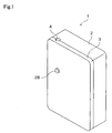
- an assay cartridge 1 is provided with a first component 2 and a second component 3.
- the first and second components are formed of transparent resin, for example, acrylic resin and polycarbonate resin mixed with antistatic agent, and the components are mutually adhered one to another with an air-tight seal via high-frequency welding.
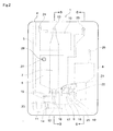
- the assay cartridge 1 is internally provided with a long and slender sample receptacle 5 having a capacity of 200 ⁇ L and extending downward in a vertical direction and further having an opening 4 at the top, reagent compartment 6, mixture measuring chamber 7, mixture compartment (hemoglobin detector) 8, detector 9, overflow receptacle 10, excess sample collector 11, and rotating valve 12.
- the bottom end of the sample receptacle 5 is connected to the rotating valve 12 through a flow path 15.
- One of the ends of the U-shaped excess sample collector 11 is connected to the rotating valve 12 through a flow path 14, and the other end is connected to the pump connector 23.
- the base of the reagent compartment 6 is connected to the rotating valve 12 through a flow path 16, and the base of the mixture compartment 8 is connected to the rotating valve 12 through a flow path 17. Furthermore, the base of the mixture measuring chamber 7 is connected to the mixture compartment 8 by parallel flow paths 18 and 19. A pellet (gate element) 20 is inserted between the flow paths 18 and 19, and electrodes 21 and 22 are respectively exposed in the flow paths 18 and 19. The detector 9 is formed by the flow paths 18 and 19, electrodes 21 and 22, and the pellet 20.
- the top end of the mixture measuring chamber 7 is connected to the top of the overflow receptacle 10 through a flow path 13. The top of each of the overflow receptacle 10, reagent compartment 6, and mixture compartment 8 respectively connected to the pump connectors 24, 25, and 26 on the back side (Fig. 3).
- a reagent injection port 27 which passes through the top of the reagent compartment 6 is provided in the front surface of the assay cartridge 1 (Fig. 2), and a cap 28 is installed in the injection port 27. Furthermore, the electrodes 21 and 22, which are respectively exposed in the flow paths 18 and 19, are pole electrodes formed of stainless steel and protrude from the back side of the assay cartridge 1, as shown in Figs. 3 through 5.
- the sample within the sample receptacle 5 is measured by the rotating valve 12.
- the measured sample is mixed with a reagent supplied from the reagent compartment 6 to prepare the analysate.
- the prepared analysate is measured in the mixture measuring chamber 7.
- the measured analysate is subjected to the detector 9 and the number and size of the included white blood cells are measured.
- the rotating valve 12 is provided with a cylinder 29, conical projection 30 extending upward from the cylinder 29, and a disk-shaped base 31 supporting the bottom end of the cylinder 29.
- Narrow channel-like first and second concavities 32 and 33 are formed in the axial direction of the cylinder 29 on the outer wall of the cylinder 29, and a channel 49 is formed in a direcxtion intersecting the axis on the bottom surface of the base.
- a drive source for rotating the rotating valve is connected to the channel 49 in a manner described later.
- Fig. 9 illustrates the measuring operation and the operation of the rotating valve 12. As shown in the drawing, the rotating valve 12 is inserted into a valve receiving hole formed on the bottom of the assay cartridge 1.
- Fig. 9(a) shows the condition when the two flow paths L1 and L2, which are formed within the assay cartridge 1, are blocked by the rotating valve 12.
- the rotating valve 12 When the rotating valve 12 is rotated to the position shown in Fig. 9(b), the flow paths L1 and L2 are connected through the first concavity 32 or second concavity 33, such that fluid is able to flow from the flow path L1 to the flow path L2.
- the rotating valve 12 When the rotating valve 12 is rotated to the position shown in Fig. 9(c), the fluid flowing from the flow path L1 to the flow path L2 is cut off by the first concavity 32 or second concavity 33, that is, fluid is measured in a quantity matching the capacity of the first concavity 32 or second concavity 33.
- the first concavity 32 or second concavity 33 holding the fluid flow cut off in Fig. 9(c) is connected to separate flow paths L3 and L4, such that the measured fluid is mixed with the fluid flowing from the flow path L3 to the flow path L4.
- the capacities of the first concavity 32 and second concavity 33 of the rotating valve 12 in the present embodiment is 2 ⁇ L in both cases.
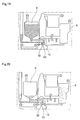
- Fig. 10 is a cross section view on the B-B arrow of Fig. 2
- Fig. 11 is a cross section view of the essential part on the C-C arrow of Fig. 10.
- the mixture measuring chamber 7 is shaped as a long and narrow hollow cylinder in a vertical direction and is tapered toward the top end and has a predetermined capacity; the top end is connected to the flow path 13, and the conical projection 30 of the rotating valve 12 extends from the bottom surface so as to seal the bottom surface of the mixture measuring chamber 7.
- the mixture measuring chamber 7 has an opening on the inner wall near the base, and a flow path 18 is connected to this opening; the center axis of the mixture measuring chamber 7 and the flow path 18 mutually intersect at right angles. Furthermore, this opening is provided below the apex of the conical projection 30, such that the cross sectional area of the flow path 18 increases in conjunction with the separation from the opening.
- a hole through the flow path 13 is for discharging excess fluid from the mixture measuring chamber 7, and a hole through the flow path 18 is for introducing fluid into the mixture measuring chamber 7.
- the fluid in the present embodiment, the fluid (analysate) is a mixture of blood and reagent
- the analysate is supplied to the mixture measuring chamber 7 through the flow path 18, the fluid level rises and the supply of the fluid is stopped when some of the fluid overflows into the overflow receptacle 10 through the flow path 13.
- the analysate fills the mixture measuring chamber 7 and predetermined quantity of the analysate is measured.
- the predetermined quantity of the analysate has quantity matching the capacity of the mixture measuring chamber 7.
- the rotating valve 12 is provided at the bottom of the mixture measuring chamber 7, and at this time the center of the opening of the flow path 18 of the mixture measuring chamber 7 is lower than the apex of the conical projection 30 of the rotating valve 12, as shown in Fig. 11, the mixture measuring chamber 7 discharges the measured fluid without any remaining residue.
- the detector 9 is provided with flow paths 18 and 19 connected in parallel to the same axis through the pellet (gate element) 20.
- the pellet 20 is formed by injection molding using a resin, and is formed as a disk with an annular projection on its exterior circumference and a small hole (through hole) 100 ⁇ m in diameter at its center.
- the pellet 20 is inserted into the flow path 19, and is fixed in place by an annular pellet fixing element 50.
- the small hole of the pellet 20 has the same axis as the flow paths 18 and 19.
- the detector 9 measures the change in electrical resistance of the analysate passing through the small hole of the pellet 20 by means of the electrodes 21 and 22.
- the assay cartridge 1 is installed so as to have a predetermined angle ⁇ relative to the gravity direction of the center axis of the small hole of the pellet 20 and flow paths 18 and 19, air bubbles contained in the analysate accumulate at the top (empty space formed by the pellet 20 and flow path 18) of the flow path 18 forward of the pellet 20, and do not adhere to the small hole of the pellet 20. Accordingly, the values measured by the electrodes 21 and 22 are not influenced by noise caused by the air bubbles.
- the reagent compartment 6 is provided with a first compartment 6a, and disposed below the first compartment 6a is a second compartment 6b which has a smaller transverse cross section area than the first compartment 6a; the first compartment 6a communicates with the second compartment 6b, and the first compartment 6a has a decreasing transverse cross section as it approaches the second compartment 6b. Furthermore, a reagent supply port to the flow path 16 is provided at a distance S above the bottom end of the second compartment 6b, and the axis of the reagent supply port faces a horizontal direction, that is a direction intersecting the sequence direction of the first compartment 6a and second compartment 6b.
- the reagent is a mixture of diluting fluid and hemolytic agent in a 2:1 ratio
- the reagent is a mixture of diluting fluid and hemolytic agent in a 2:1 ratio
- the cap 28 is placed on the reagent injection port 27, and a tape seal is adhered to the pump connector 25 to prevent leakage of the dilution fluid.
- the air in the reagent compartment 6 is replaced by the dilution fluid, but the air in the flow path 16 remains and is not replaced by the dilution fluid since the reagent compartment 6 has the structure described above. Accordingly, an air gap is created between the outer wall of the rotating valve 12 and the dilution fluid within the reagent compartment 6, such that the dilution fluid does not leak to the outside through the outer wall of the rotating valve 12 even when the dilution fluid is stored for a long period in the reagent compartment 6.
- Fig. 12 is a cross section view on the D-D arrow of Fig. 2.
- the mixture compartment 8 is interposed between a photoemitter 34 and a photoreceptor 35 of the analyzing unit 36, such that the transmitted light (transmitted light intensity) of the fluid accommodated in the mixture compartment 8 can be measured.
- Fig. 13 is a perspective view of the exterior of the analyzing unit 36, which is provided with a liquid crystal display 37, keyboard 38, and door 39 on its front panel.
- the door 39 is opened and the assay cartridge 1 is loaded into the analyzing unit 36, then the door 39 is closed; this operation connects the electrodes 21 and 22 of the assay cartridge 1 to the analyzing unit 36, and connects the pump connectors 23, 24, 25, and 26, and arranges the photoemitter 34 and photoreceptor 35 as shown in Fig. 12.
- the center axes of the pellet 20 and flow paths 18 and 19 of the assay cartridge 1 are horizontal (at right angles to the gravity direction).
- Fig. 14 is a block diagram of the analyzer produced by loading the assay cartridge 1 into the analyzing unit 36.
- the assay cartridge 1 is shown expanded in a planar view to facilitate understanding of the structure.
- a direct current constant-current power supply 40 provided in the analyzing unit 36 is connected to the electrodes 21 and 22 of the assay cartridge 1, and a syringe pump 41 is connected to the pump connectors 23 through 26 of the assay cartridge 1 through a valve unit 42.
- the output shaft of a stepping motor 48 is coupled to the channel 49 of the rotating valve 12 through a coupling not shown in the drawing.
- the valve unit 42 is provided with two-way electromagnetic valves SV1 through SV6, and a pressure sensor 43 for detecting the pressure of the syringe pump 41 is connected to the outlet of the syringe pump 41.
- Valves SV3, SV4, and SV5 are respectively provided with air release openings 44.
- a controller 45 is provided with a microcomputer which includes a CPU, ROM, RAM and the like, and stores programs for calculating analysis results and driving the valves and motor.
- the controller 45 receives the output from the keyboard 38 and the pressure sensor 43, and drives the syringe pump 41, the stepping motor 48, valves SV1 through SV6, and photoemitter 34.
- the controller 45 counts the white blood cells based on the signals obtained from the electrodes 21 and 22, calculates the particle size and creates a particle size distribution, and further calculates the amount of hemoglobin based on the signals obtained from the photoreceptor 35. These results are displayed on the liquid crystal display 37.
- step S1 of Fig. 15 when initialization settings are specified to the analyzing unit 36 through the keyboard 38, the syringe pump 41, stepping motor 48 and valves SV1 through SV6 are set to the initial states.
- valves SV1 through SV6 are all turned OFF, that is, set to the condition shown in Fig. 14.
- a user injects 10 to 150 ⁇ L of whole blood as a sample (specimen) into the sample receptacle 5 of the assay cartridge 1 accommodated beforehand in the reagent compartment 6.
- a capillary blood collection tube filled with suctioned whole blood may be inserted into the sample receptacle 5.
- a user removes the tape seal adhered to the pump connector 25 on the back side of the assay cartridge 1, opens the door 39 on the front panel of the analyzing unit 36, loads the assay cartridge 1 therein, and closes the door 39 (step S2).
- the rotating valve 12 is rotated through a predetermined angle, 2 ⁇ L of sample is cut off and measured by the first concavity 32, as shown in Fig. 19.
- the rotating valve 12 simultaneously connects the sample compartment 6 and mixture compartment 8 through the second concavity 33 (step S7).
- valves SV1 and SV2 are turned ON, and the valves SV3 through SV6 are turned OFF (step S8), and when the syringe pump 41 has suctioned for a predetermined time T2 (steps S9 through S11), dilution fluid migrates from the reagent compartment 6 through the second concavity 33 to the mixture compartment 8, as shown in Fig. 20.
- the photoemitter is lighted, and a hemoglobin concentration blank value is measured by the photoreceptor 35 (step S12).
- the rotating valve 12 connects the reagent compartment 6 and the mixture compartment 8 through the first concavity 32 (step S13).
- valves SV1, SV3, and SV4 are turned ON, and valves SV2, SV5 and SV6 are turned OFF (step S14), and when the syringe pump 41 has suctioned for a predetermined time T3 (step S15 through S17), the sample accommodated in the first concavity 32 migrates to the mixture compartment 8 and the reagent compartment 6, as shown in Fig. 22.
- valves SV1 and SV2 are turned ON, and valves SV3 through SV6 are turned OFF, and when the syringe pump 41 suctions for a predetermined time T4 (steps S19 through S21), the sample and dilution fluid again migrate to the mixture compartment 8, as shown in Fig. 23, and the sample is thoroughly diluted by the dilution fluid. That is, the analysate prepared by diluting the sample with the dilution fluid is stored in the mixture compartment 8. Then, the photoemitter 34 is again lighted and the hemoglobin concentration is again measured by the photoreceptor 35 (step S22).
- the rotating valve 12 When the rotating valve 12 is rotated through a predetermined angle, the rotating valve 12 completely blocks the flow path between the sample receptacle 5 and the excess sample collector 11, and the flow path between the reagent compartment 6 and the mixture compartment 8 (step S23).
- valves SV3 and SV6 are turned ON, and valves SV1, SV2, SV4, and SV5 are turned OFF (step S24), the syringe pump 41 suctions for a predetermined time T5 (steps S25 through S27), and the analysate in the mixture compartment 8 migrates to the mixture measuring chamber 7 through the pellet 20, as shown in Fig. 25, and after the mixture measuring chamber 7 is filled, some analysate overflows to the overflow collector 10. In this way analysate is measured in a quantity matching the capacity of the mixture measuring chamber 7.
- valves SV1, SV2, SV5, and SV6 are turned ON, and valves SV3 and SV4 are turned OFF, and when the syringe pump 41 applies suction, the analysate in the mixture measuring chamber 7 starts to migrate to the mixture compartment 8 through the pellet 20, as shown in Fig. 26 (steps S28 and S29).
- the rotating valve 12 When the rotating valve 12 is rotated through a predetermined angle, the rotating valve 12 connects the sample receptacle 5 and the excess sample collector 11 through the second concavity 33 while blocking the flow path between the reagent compartment 6 and the mixture compartment 8, as shown in Fig. 27 (step S32).
- valves SV1 through SV6 are turned OFF (initial setting), and when the syringe pump 41 is suctioned for a predetermined time T6, all the sample stored in the sample receptacle 5 migrates to the excess sample collector 11 (steps S33 through S36).
- step S37 The user then removes the assay cartridge 1 from the analyzing unit 36 and discards the cartridge in this state.
- the controller 45 When white blood cells pass through the small hole, there is a change in the electrical resistance between the electrodes 21 and 22 since the liquid component is eliminated by the volume of the white blood cells, and this change can be detected as a pulse voltage generated between the electrodes 21 and 22. Accordingly, the controller 45 counts the number of white blood cells from the number of pulses. Since the height of the pulse is proportional to the volume of the particle, the controller 45 detects the height of the pulse, calculates the spherical equivalent of the white blood cell, and creates a particle size distribution.
- the controller 45 determines the transmission light intensity (blank value) of the dilution fluid obtained by the photoreceptor 35, and the light absorption of the analysate from the transmission light intensity of the analysate using well known methods, and calculates the amount of hemoglobin in the sample from the determined light absorption.
- the present embodiment has been described in terms of an analyzer including an analyzing unit 36 and an assay cartridge 1 removably loaded in the analyzing unit 36, the present invention is not limited to this arrangement inasmuch as a hemocytometer provided with a non-user-detachable detector may include a conical projection 30 and mixture measuring chamber 7.
- the present invention is also applicable to urine analyzers for analyzing tangible components in urine.
- the present invention is applicable to industrial analyzers for analyzing organic powders such as powdered food, and inorganic powers such as toner and pigment.
- the present invention is not limited to this arrangement inasmuch as blood diluted with dilution fluid, blood subjected to hemolysis with hemolytic agent, and suspension fluid formed by powder particles suspended in a suitable fluid also may be used.
- the conical projection 30 is integratedly formed with the rotating valve 12 in the present embodiment, the present invention is not limited to this arrangement inasmuch as the conical projection may also be integratedly formed with the mixture measuring chamber 7.
- a flow cell and optical elements for detecting an optical signal from the analysate flowing in the flow cell may also be used as the detector.
- the optical signal detected by such a detector may be a scattered light signal, fluorescent light signal or the like.
Landscapes
- Chemical & Material Sciences (AREA)
- Health & Medical Sciences (AREA)
- Analytical Chemistry (AREA)
- General Health & Medical Sciences (AREA)
- Dispersion Chemistry (AREA)
- Clinical Laboratory Science (AREA)
- Hematology (AREA)
- Chemical Kinetics & Catalysis (AREA)
- Physics & Mathematics (AREA)
- Life Sciences & Earth Sciences (AREA)
- Biochemistry (AREA)
- General Physics & Mathematics (AREA)
- Immunology (AREA)
- Pathology (AREA)
- Automatic Analysis And Handling Materials Therefor (AREA)
Abstract
Description
- The present invention relates to an analyzer for analyzing fluid samples by loading the removable assay cartridge provided with a detector, an assay cartridge loadable into the analyzer, and analyzing method for analyzing fluid samples using the assay cartridge.
- Analyzers for analyzing fluid samples often use an assay device provided with a maintenance-free detector which is installed in a replaceable cartridge.
- For example, United States Laid-Open Patent Publication No. 2002-172617 discloses an assay unit provided with a rotating valve for preparing analysate by measuring a fixed quantity of sample and mixing the sample and a reagent, and an electrical resistance measuring part for detecting a signal from a prepared analysate. This assay unit is removably installed in the assay device.
- In the assay unit disclosed in United States Laid-Open Patent Publication No. 2002-172617, a predetermined quantity of analysate is passed through a small hole in the electrical resistance measuring part by means of the suction operation perforemd for a specific time by a syringe pump provided in the assay device. Then, the number of white blood cells contained in the analysate that has passed through the small hole is counted. That is, in the assay unit, the quantity of analysate is measured by the suction time of the syringe pump.
- Before the suction operation of the syringe pump in this assay unit, however, the flow path is filled with air rather than fluid from the syringe pump to the electrical resistance measuring part. This air is greatly expanded compared to the fluid when the suction force is applied. Accordingly, a problem arises inasmuch as the quantity of analysate actually transferred and which passes through the small hole is not stable since an amount of expanded air is included even when the syringe pump operates a predetermined length of time. Therefore, in conventional assay units the quantity of analysate used for signal detection is unstable, and errors may occur in the analysis result.
- The scope of the present invention is defined solely by the appended claims, and is not affected to any degree by the statements within this summary.
- An object of one embodiment of the present invention is to improve an accuracy of a result of analysis.
- The first aspect of the present invention relates to an analyzer comprising an assay cartridge comprising a mixture measuring chamber for receiving a mixture of a sample and a dilution fluid, and a detector for detecting a signal from the mixture supplied from the mixture measuring chamber, the mixture measuring chamber having a predetermined capacity, and an amount of the mixture supplied to the detector being substantially equal to the capacity of the mixture measuring chamber; and an analyzing unit comprising a controller for analyzing the signal detected by the detector; wherein the assay cartridge is detachably mountable to the analyzing unit.
- The second aspect of the present invention relates to a cartridge comprising a mixture measuring chamber for receiving a mixture of a sample and a dilution fluid, the mixture measuring chamber having a predetermined capacity; and a detector for detecting a signal from the mixture supplied from the mixture measuring chamber, an amount of the mixture supplied to the detector being substantially equal to the capacity of the mixture measuring chamber.
- The third aspect of the present invention relates to analyzing method embodying comprising a step of mounting an assay cartridge, which comprises a mixture measuring chamber having a predetermined capacity and a detector for detecting a signal from a mixture of a sample and a reagent, in an analyzer which comprises a controller for analyzing the signal detected by the detector; a step of introducing the mixture to the mixture measuring chamber; a step of supplying the mixture from the mixture measuring chamber to the detector; a step of detecting a signal from the mixture by the detector; and a step of analyzing the signals by the controller, wherein an amount of the mixture supplied to the detector is substantially equal to the capacity of the mixture measuring chamber.
- The fourth aspect of the present invention relates to an analyzer comprising an assay unit, which comprises an assay cartridge, which comprises a mixture receptacle having an opening on the inner wall near the base and capable of accommodating a mixture of sample and reagent; a projection provided on the base of the mixture receptacle and extending upward from the base; and a detector for detecting a signal from the mixture supplied through the opening; and an analyzing unit, which comprises a controller for analyzing the signal detected by the detector; wherein the assay cartridge is detachably mountable to the analyzing unit.
- The fifth aspect of the present invention relates to a cartridge comprising a mixture receptacle capable of accommodating a mixture of a sample and reagent, and comprising an opening on the inner wall near the base; a projection provided on the base of the mixture receptacle and extending upward from the base; and a detector for detecting a signal from the mixture supplied through the opening.
-
- Fig. 1 is a perspective view of an embodiment of the assay cartridge of the present invention;
- Fig. 2 is a front view of an embodiment of the assay cartridge of the present invention;
- Fig. 3 is a back view of an embodiment of the assay cartridge of the present invention;
- Fig. 4 is a top view of an embodiment of the assay cartridge of the present invention;
- Fig. 5 is a bottom view of an embodiment of the assay cartridge of the present invention;
- Fig. 6 is a front view of an embodiment of the rotating valve of the present invention;
- Fig. 7 is a top view of an embodiment of the rotating valve of the present invention;
- Fig. 8 is a cross section view on the A-A arrow;
- Fig. 9 illustrates the operation of an embodiment of the rotating valve of the present invention;
- Fig. 10 is a cross section view on the B-B arrow of Fig. 2;
- Fig. 11 is a cross section view on the C-C arrow of Fig. 10;
- Fig. 12 is a cross section view on the D-D arrow of Fig. 2;
- Fig. 13 is a perspective view of an embodiment of the analyzing unit of the present invention;
- Fig. 14 is a block diagram showing the structure of an embodiment of the analyzer of the present invention in which an assay cartridge is loaded in the analyzing unit;
- Figs. 15 and 16 are flow charts showing the operation of an embodiment of the analyzer of the present invention; and
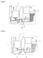
- Figs. 17 through 27 illustrate the conditions of an embodiment of the assay cartridge of the present invention.
-
- The preferred embodiments of the present invention are described hereinafter.
- As shown in Fig. 1, an
assay cartridge 1 is provided with afirst component 2 and asecond component 3. The first and second components are formed of transparent resin, for example, acrylic resin and polycarbonate resin mixed with antistatic agent, and the components are mutually adhered one to another with an air-tight seal via high-frequency welding. - As shown in Figs. 2 and 3, the
assay cartridge 1 is internally provided with a long andslender sample receptacle 5 having a capacity of 200 µL and extending downward in a vertical direction and further having anopening 4 at the top,reagent compartment 6,mixture measuring chamber 7, mixture compartment (hemoglobin detector) 8,detector 9,overflow receptacle 10,excess sample collector 11, and rotatingvalve 12. The bottom end of thesample receptacle 5 is connected to the rotatingvalve 12 through aflow path 15. One of the ends of the U-shapedexcess sample collector 11 is connected to the rotatingvalve 12 through aflow path 14, and the other end is connected to thepump connector 23. - The base of the
reagent compartment 6 is connected to the rotatingvalve 12 through aflow path 16, and the base of themixture compartment 8 is connected to the rotatingvalve 12 through aflow path 17. Furthermore, the base of themixture measuring chamber 7 is connected to themixture compartment 8 byparallel flow paths flow paths electrodes flow paths detector 9 is formed by theflow paths electrodes pellet 20. The top end of themixture measuring chamber 7 is connected to the top of theoverflow receptacle 10 through aflow path 13. The top of each of theoverflow receptacle 10,reagent compartment 6, andmixture compartment 8 respectively connected to thepump connectors - A
reagent injection port 27 which passes through the top of thereagent compartment 6 is provided in the front surface of the assay cartridge 1 (Fig. 2), and acap 28 is installed in theinjection port 27. Furthermore, theelectrodes flow paths assay cartridge 1, as shown in Figs. 3 through 5. - When the
assay cartridge 1 of the aforesaid construction is loaded in an analyzing unit described later, the sample within thesample receptacle 5 is measured by the rotatingvalve 12. The measured sample is mixed with a reagent supplied from thereagent compartment 6 to prepare the analysate. - After the hemoglobin concentration of the prepared analysate is measured in the
mixture compartment 8, the prepared analysate is measured in themixture measuring chamber 7. The measured analysate is subjected to thedetector 9 and the number and size of the included white blood cells are measured. - As shown in Figs. 6 through 8, the rotating
valve 12 is provided with acylinder 29,conical projection 30 extending upward from thecylinder 29, and a disk-shaped base 31 supporting the bottom end of thecylinder 29. Narrow channel-like first andsecond concavities cylinder 29 on the outer wall of thecylinder 29, and achannel 49 is formed in a direcxtion intersecting the axis on the bottom surface of the base. A drive source for rotating the rotating valve is connected to thechannel 49 in a manner described later. - Fig. 9 illustrates the measuring operation and the operation of the rotating
valve 12. As shown in the drawing, the rotatingvalve 12 is inserted into a valve receiving hole formed on the bottom of theassay cartridge 1. - Fig. 9(a) shows the condition when the two flow paths L1 and L2, which are formed within the
assay cartridge 1, are blocked by the rotatingvalve 12. - When the
rotating valve 12 is rotated to the position shown in Fig. 9(b), the flow paths L1 and L2 are connected through thefirst concavity 32 orsecond concavity 33, such that fluid is able to flow from the flow path L1 to the flow path L2. When therotating valve 12 is rotated to the position shown in Fig. 9(c), the fluid flowing from the flow path L1 to the flow path L2 is cut off by thefirst concavity 32 orsecond concavity 33, that is, fluid is measured in a quantity matching the capacity of thefirst concavity 32 orsecond concavity 33. - When the
rotating valve 12 is rotated to the position shown in Fig. 9(d), thefirst concavity 32 orsecond concavity 33 holding the fluid flow cut off in Fig. 9(c) is connected to separate flow paths L3 and L4, such that the measured fluid is mixed with the fluid flowing from the flow path L3 to the flow path L4. In this way the rotatingvalve 12 opens and closes the flow paths, and measures the fluid flow. The capacities of thefirst concavity 32 andsecond concavity 33 of therotating valve 12 in the present embodiment, is 2 µL in both cases. - Fig. 10 is a cross section view on the B-B arrow of Fig. 2, and Fig. 11 is a cross section view of the essential part on the C-C arrow of Fig. 10. As shown in these drawings, the
mixture measuring chamber 7 is shaped as a long and narrow hollow cylinder in a vertical direction and is tapered toward the top end and has a predetermined capacity; the top end is connected to theflow path 13, and theconical projection 30 of therotating valve 12 extends from the bottom surface so as to seal the bottom surface of themixture measuring chamber 7. - The
mixture measuring chamber 7 has an opening on the inner wall near the base, and aflow path 18 is connected to this opening; the center axis of themixture measuring chamber 7 and theflow path 18 mutually intersect at right angles. Furthermore, this opening is provided below the apex of theconical projection 30, such that the cross sectional area of theflow path 18 increases in conjunction with the separation from the opening. - A hole through the
flow path 13 is for discharging excess fluid from themixture measuring chamber 7, and a hole through theflow path 18 is for introducing fluid into themixture measuring chamber 7. - When fluid (in the present embodiment, the fluid (analysate) is a mixture of blood and reagent) is measured in the
mixture measuring chamber 7, the analysate is supplied to themixture measuring chamber 7 through theflow path 18, the fluid level rises and the supply of the fluid is stopped when some of the fluid overflows into theoverflow receptacle 10 through theflow path 13. In this way the analysate fills themixture measuring chamber 7 and predetermined quantity of the analysate is measured. The predetermined quantity of the analysate has quantity matching the capacity of themixture measuring chamber 7. - Then, the measured analysate is discharged to the
flow path 18. The rotatingvalve 12 is provided at the bottom of themixture measuring chamber 7, and at this time the center of the opening of theflow path 18 of themixture measuring chamber 7 is lower than the apex of theconical projection 30 of therotating valve 12, as shown in Fig. 11, themixture measuring chamber 7 discharges the measured fluid without any remaining residue. - As shown in Fig. 11, the
detector 9 is provided withflow paths pellet 20 is formed by injection molding using a resin, and is formed as a disk with an annular projection on its exterior circumference and a small hole (through hole) 100 µm in diameter at its center. Thepellet 20 is inserted into theflow path 19, and is fixed in place by an annularpellet fixing element 50. The small hole of thepellet 20 has the same axis as theflow paths - As shall be described later, when the analysate flows from the
mixture measuring chamber 7 to themixture compartment 8, thedetector 9 measures the change in electrical resistance of the analysate passing through the small hole of thepellet 20 by means of theelectrodes assay cartridge 1 is installed so as to have a predetermined angle relative to the gravity direction of the center axis of the small hole of thepellet 20 andflow paths pellet 20 and flow path 18) of theflow path 18 forward of thepellet 20, and do not adhere to the small hole of thepellet 20. Accordingly, the values measured by theelectrodes - As shown in Fig. 10, the
reagent compartment 6 is provided with afirst compartment 6a, and disposed below thefirst compartment 6a is asecond compartment 6b which has a smaller transverse cross section area than thefirst compartment 6a; thefirst compartment 6a communicates with thesecond compartment 6b, and thefirst compartment 6a has a decreasing transverse cross section as it approaches thesecond compartment 6b. Furthermore, a reagent supply port to theflow path 16 is provided at a distance S above the bottom end of thesecond compartment 6b, and the axis of the reagent supply port faces a horizontal direction, that is a direction intersecting the sequence direction of thefirst compartment 6a andsecond compartment 6b. Before using theassay cartridge 1, 1000 µL of diluting fluid (in the present embodiment, the reagent is a mixture of diluting fluid and hemolytic agent in a 2:1 ratio) is injected as a reagent through the reagent supply port into thereagent compartment 6. - Directly after the injection, the
cap 28 is placed on thereagent injection port 27, and a tape seal is adhered to thepump connector 25 to prevent leakage of the dilution fluid. When the dilution fluid is injected into thereagent compartment 6, the air in thereagent compartment 6 is replaced by the dilution fluid, but the air in theflow path 16 remains and is not replaced by the dilution fluid since thereagent compartment 6 has the structure described above. Accordingly, an air gap is created between the outer wall of therotating valve 12 and the dilution fluid within thereagent compartment 6, such that the dilution fluid does not leak to the outside through the outer wall of therotating valve 12 even when the dilution fluid is stored for a long period in thereagent compartment 6. - Fig. 12 is a cross section view on the D-D arrow of Fig. 2.
- When the
assay cartridge 1 is loaded into the analyzingunit 36 as described later, themixture compartment 8 is interposed between aphotoemitter 34 and aphotoreceptor 35 of the analyzingunit 36, such that the transmitted light (transmitted light intensity) of the fluid accommodated in themixture compartment 8 can be measured. - Fig. 13 is a perspective view of the exterior of the analyzing
unit 36, which is provided with aliquid crystal display 37,keyboard 38, anddoor 39 on its front panel. To use theassay cartridge 1, thedoor 39 is opened and theassay cartridge 1 is loaded into the analyzingunit 36, then thedoor 39 is closed; this operation connects theelectrodes assay cartridge 1 to the analyzingunit 36, and connects thepump connectors photoemitter 34 andphotoreceptor 35 as shown in Fig. 12. In this case, the center axes of thepellet 20 andflow paths assay cartridge 1 are horizontal (at right angles to the gravity direction). - Fig. 14 is a block diagram of the analyzer produced by loading the
assay cartridge 1 into the analyzingunit 36. In the drawing, theassay cartridge 1 is shown expanded in a planar view to facilitate understanding of the structure. - As shown in the drawing, a direct current constant-
current power supply 40 provided in the analyzingunit 36 is connected to theelectrodes assay cartridge 1, and asyringe pump 41 is connected to thepump connectors 23 through 26 of theassay cartridge 1 through avalve unit 42. The output shaft of a steppingmotor 48 is coupled to thechannel 49 of therotating valve 12 through a coupling not shown in the drawing. - The
valve unit 42 is provided with two-way electromagnetic valves SV1 through SV6, and apressure sensor 43 for detecting the pressure of thesyringe pump 41 is connected to the outlet of thesyringe pump 41. Valves SV3, SV4, and SV5 are respectively provided withair release openings 44. Acontroller 45 is provided with a microcomputer which includes a CPU, ROM, RAM and the like, and stores programs for calculating analysis results and driving the valves and motor. - The
controller 45 receives the output from thekeyboard 38 and thepressure sensor 43, and drives thesyringe pump 41, the steppingmotor 48, valves SV1 through SV6, andphotoemitter 34. - The
controller 45 counts the white blood cells based on the signals obtained from theelectrodes photoreceptor 35. These results are displayed on theliquid crystal display 37. - The operation of the analyzer shown in Fig. 14 is described below using the flow charts of Figs. 15 and 16 and the condition illustrations of Figs. 17 through 27.
- First, in step S1 of Fig. 15, when initialization settings are specified to the analyzing
unit 36 through thekeyboard 38, thesyringe pump 41, steppingmotor 48 and valves SV1 through SV6 are set to the initial states. - At this time the valves SV1 through SV6 are all turned OFF, that is, set to the condition shown in Fig. 14.
- Then, using an injection device or pipette, a user injects 10 to 150 µL of whole blood as a sample (specimen) into the
sample receptacle 5 of theassay cartridge 1 accommodated beforehand in thereagent compartment 6. Alternatively, a capillary blood collection tube filled with suctioned whole blood may be inserted into thesample receptacle 5. - Next, a user removes the tape seal adhered to the
pump connector 25 on the back side of theassay cartridge 1, opens thedoor 39 on the front panel of the analyzingunit 36, loads theassay cartridge 1 therein, and closes the door 39 (step S2). - At this time the rotating
valve 12 of theassay cartridge 1 is connected to thesample receptacle 5 and theexcess sample collector 11 through thefirst concavity 32, as shown in Fig. 17. - Then, the user specifies the [start] operation from the keyboard 38 (step S3).
- In this way, when the
syringe pump 41 has suctioned for a time T1 (steps S4 through S6), the sample migrates from thesample receptacle 5 through thefirst concavity 32 to theexcess sample collector 11, as shown in Fig. 18. - Then, the rotating
valve 12 is rotated through a predetermined angle, 2 µL of sample is cut off and measured by thefirst concavity 32, as shown in Fig. 19. - The rotating
valve 12 simultaneously connects thesample compartment 6 andmixture compartment 8 through the second concavity 33 (step S7). - Then, the valves SV1 and SV2 are turned ON, and the valves SV3 through SV6 are turned OFF (step S8), and when the
syringe pump 41 has suctioned for a predetermined time T2 (steps S9 through S11), dilution fluid migrates from thereagent compartment 6 through thesecond concavity 33 to themixture compartment 8, as shown in Fig. 20. Here, the photoemitter is lighted, and a hemoglobin concentration blank value is measured by the photoreceptor 35 (step S12). - Subsequently, when the rotating
value 12 is rotated through a predetermined angle, the rotatingvalve 12 connects thereagent compartment 6 and themixture compartment 8 through the first concavity 32 (step S13). - Then, the valves SV1, SV3, and SV4 are turned ON, and valves SV2, SV5 and SV6 are turned OFF (step S14), and when the
syringe pump 41 has suctioned for a predetermined time T3 (step S15 through S17), the sample accommodated in thefirst concavity 32 migrates to themixture compartment 8 and thereagent compartment 6, as shown in Fig. 22. - Thereafter, the valves SV1 and SV2 are turned ON, and valves SV3 through SV6 are turned OFF, and when the
syringe pump 41 suctions for a predetermined time T4 (steps S19 through S21), the sample and dilution fluid again migrate to themixture compartment 8, as shown in Fig. 23, and the sample is thoroughly diluted by the dilution fluid. That is, the analysate prepared by diluting the sample with the dilution fluid is stored in themixture compartment 8. Then, thephotoemitter 34 is again lighted and the hemoglobin concentration is again measured by the photoreceptor 35 (step S22). - When the
rotating valve 12 is rotated through a predetermined angle, the rotatingvalve 12 completely blocks the flow path between thesample receptacle 5 and theexcess sample collector 11, and the flow path between thereagent compartment 6 and the mixture compartment 8 (step S23). - Then, the valves SV3 and SV6 are turned ON, and valves SV1, SV2, SV4, and SV5 are turned OFF (step S24), the
syringe pump 41 suctions for a predetermined time T5 (steps S25 through S27), and the analysate in themixture compartment 8 migrates to themixture measuring chamber 7 through thepellet 20, as shown in Fig. 25, and after themixture measuring chamber 7 is filled, some analysate overflows to theoverflow collector 10. In this way analysate is measured in a quantity matching the capacity of themixture measuring chamber 7. - Thereafter, the valves SV1, SV2, SV5, and SV6 are turned ON, and valves SV3 and SV4 are turned OFF, and when the
syringe pump 41 applies suction, the analysate in themixture measuring chamber 7 starts to migrate to themixture compartment 8 through thepellet 20, as shown in Fig. 26 (steps S28 and S29). - At this time the change in the electrical resistance of the analysate passing through the
pellet 20 is detected by theelectrodes syringe pump 41, and when all the analysate measured by themixture measuring chamber 7 has passed through thepellet 20, the suction pressure of thesyringe pump 41 quickly changes. This change in pressure is detected by thepressure sensor 43, and the suction of thesyringe pump 41 is stopped (steps S30 and S31). That is, in this way the number and size of all the white blood cells are measured in the analysate quantity matching the capacity of themixture measuring chamber 7. - When the
rotating valve 12 is rotated through a predetermined angle, the rotatingvalve 12 connects thesample receptacle 5 and theexcess sample collector 11 through thesecond concavity 33 while blocking the flow path between thereagent compartment 6 and themixture compartment 8, as shown in Fig. 27 (step S32). - All the valves SV1 through SV6 are turned OFF (initial setting), and when the
syringe pump 41 is suctioned for a predetermined time T6, all the sample stored in thesample receptacle 5 migrates to the excess sample collector 11 (steps S33 through S36). - The user then removes the
assay cartridge 1 from the analyzingunit 36 and discards the cartridge in this state (step S37). - As shown in Fig. 14, when a constant current is supplied from the direct current constant
current power supply 40 through theelectrodes pellet 20 which is provided with a small hole, the resistance between theelectrodes - When white blood cells pass through the small hole, there is a change in the electrical resistance between the
electrodes electrodes controller 45 counts the number of white blood cells from the number of pulses. Since the height of the pulse is proportional to the volume of the particle, thecontroller 45 detects the height of the pulse, calculates the spherical equivalent of the white blood cell, and creates a particle size distribution. Thecontroller 45 determines the transmission light intensity (blank value) of the dilution fluid obtained by thephotoreceptor 35, and the light absorption of the analysate from the transmission light intensity of the analysate using well known methods, and calculates the amount of hemoglobin in the sample from the determined light absorption. - Although the present embodiment has been described in terms of an analyzer including an analyzing
unit 36 and anassay cartridge 1 removably loaded in the analyzingunit 36, the present invention is not limited to this arrangement inasmuch as a hemocytometer provided with a non-user-detachable detector may include aconical projection 30 andmixture measuring chamber 7. The present invention is also applicable to urine analyzers for analyzing tangible components in urine. Furthermore, the present invention is applicable to industrial analyzers for analyzing organic powders such as powdered food, and inorganic powers such as toner and pigment. - Although blood and a fluid mixture of reagent including dilution fluid and hemolytic agent are used as the analysate in the present embodiment, the present invention is not limited to this arrangement inasmuch as blood diluted with dilution fluid, blood subjected to hemolysis with hemolytic agent, and suspension fluid formed by powder particles suspended in a suitable fluid also may be used.
- Although the
conical projection 30 is integratedly formed with the rotatingvalve 12 in the present embodiment, the present invention is not limited to this arrangement inasmuch as the conical projection may also be integratedly formed with themixture measuring chamber 7. - A flow cell and optical elements for detecting an optical signal from the analysate flowing in the flow cell may also be used as the detector. The optical signal detected by such a detector may be a scattered light signal, fluorescent light signal or the like.
Claims (27)
- An analyzer comprising:wherein the assay cartridge is detachably mountable to the analyzing unit.an assay cartridge comprising a mixture measuring chamber for receiving a mixture of a sample and a dilution fluid, and a detector for detecting a signal from the mixture supplied from the mixture measuring chamber, the mixture measuring chamber having a predetermined capacity, and an amount of the mixture supplied to the detector being substantially equal to the capacity of the mixture measuring chamber; andan analyzing unit comprising a controller for analyzing the signal detected by the detector;
- The analyzer of Claim 1, wherein the mixture measuring chamber comprises an inlet for introducing mixture into the interior, and a discharge port for discharging excess mixture; and
wherein the assay cartridge further comprises a compartment for accommodating excess mixture discharged from the discharge port. - The analyzer of Claim 2, wherein the mixture migrates to the detector through the inlet from the inside of the mixture measuring chamber.
- The analyzer of Claim 1, wherein the detector comprises a hole for the passage of the mixture, and electrodes arranged with the hole interposed therebetween.
- The analyzer of Claim 1, wherein the analyzing unit further comprises a pump for migrating the mixture from the mixture measuring chamber to the detector.
- The analyzer of Claim 1, wherein the detector detects a signal from all of the mixture supplied from the mixture measuring chamber.
- The analyzer of Claim 1, wherein the mixture measuring chamber comprises a projection disposed on the interior base and extending upward from the base.
- An assay cartridge detachably mountable to an analyzer, the assay cartridge comprising:a mixture measuring chamber for receiving a mixture of a sample and a dilution fluid, the mixture measuring chamber having a predetermined capacity; anda detector for detecting a signal from the mixture supplied from the mixture measuring chamber, an amount of the mixture supplied to the detector being substantially equal to the capacity of the mixture measuring chamber.
- The assay cartridge of Claim 8, wherein the mixture measuring chamber comprises an inlet for introducing the mixture into the interior, and a discharge outlet for discharging excess mixture; and wherein the assay cartridge further comprises a compartment for accommodating excess mixture discharged from the discharge outlet.
- The assay cartridge of Claim 9, wherein the mixture migrates from the interior of the mixture measuring chamber to the detector through the inlet.
- The assay cartridge of Claim 8, wherein the detector comprises a hole for the passage of the mixture, and electrodes arranged with the hole interposed therebetween.
- The assay cartridge of Claim 8, wherein the detector detects a signal from all of the mixture supplied from the mixture measuring chamber.
- The assay cartridge of Claim 8, wherein the mixture measuring chamber comprises a projection disposed on the interior base and extending upward from the base.
- An analyzing method comprising:wherein an amount of the mixture supplied to the detector is substantially equal to the capacity of the mixture measuring chamber.a step of mounting an assay cartridge, which comprises a mixture measuring chamber having a predetermined capacity and a detector for detecting a signal from a mixture of a sample and a reagent, in an analyzer which comprises a controller for analyzing the signal detected by the detector;a step of introducing the mixture to the mixture measuring chamber;a step of supplying the mixture from the mixture measuring chamber to the detector;a step of detecting a signal from the mixture by the detector; anda step of analyzing the signals by the controller,
- The analyzing method of Claim 14, further comprising a step of removing the assay cartridge from the analyzer.
- The analyzing method of Claim 14, wherein the step of receiving the mixture comprises a step of overflowing mixture from the mixture measuring chamber.
- The analyzing method of Claim 14, wherein the step of signal detection comprises:a step of passing mixture through a hole;a step of applying an electric current to the mixture passing through the hole; anda step of acquiring the potential difference of the mixture passing through the hole.
- An analyzer comprising:wherein the assay cartridge is detachably mountable to the analyzing unit.an assay cartridge, which comprises a mixture receptacle having an opening on the inner wall near the base and capable of accommodating a mixture of sample and reagent; a projection provided on the base of the mixture receptacle and extending upward from the base; and a detector for detecting a signal from the mixture supplied through the opening; andan analyzing unit, which comprises a controller for analyzing the signal detected by the detector;
- The analyzer of Claim 18, wherein the projection is approximately conical.
- The analyzer of Claim 18, wherein the opening is arranged so as to position the center of opening below the apex of the projection.
- The analyzer of Claim 18, wherein the detector comprises a connecting flow path communicating with the opening and intersecting the center axis of the projection at substantially right angles.
- The analyzer of Claim 21, wherein the connecting flow path has a cross section area that increases in conjunction with the separation from the opening.
- The analyzer of Claim 21, wherein the mixture receptacle and the connecting flow path are integratedly formed.
- The analyzer of Claim 18, wherein the detector comprises a partition having a hole for the passage of the mixture, and electrodes arranged with the hole interposed therebetween.
- The analyzer of Claim 18, wherein the mixture receptacle has a long and narrow shape in the vertical direction and a circular transverse cross section.
- The analyzer of Claim 18, wherein the assay cartridge further comprises a measuring valve for measuring a sample; and the projection is integratedly formed with the measuring valve.
- An assay cartridge detachably mountable to an analyzer, the assay cartridge comprising:a mixture receptacle capable of accommodating a mixture of a sample and reagent, and comprising an opening on the inner wall near the base;a projection provided on the base of the mixture receptacle and extending upward from the base; anda detector for detecting a signal from the mixture supplied through the opening.
Applications Claiming Priority (4)
| Application Number | Priority Date | Filing Date | Title |
|---|---|---|---|
| JP2003400059 | 2003-11-28 | ||
| JP2003400087 | 2003-11-28 | ||
| JP2003400087A JP2005164276A (en) | 2003-11-28 | 2003-11-28 | Analyzer and measuring unit |
| JP2003400059A JP2005164274A (en) | 2003-11-28 | 2003-11-28 | Analyzer and measuring unit |
Publications (1)
| Publication Number | Publication Date |
|---|---|
| EP1535667A1 true EP1535667A1 (en) | 2005-06-01 |
Family
ID=34467834
Family Applications (1)
| Application Number | Title | Priority Date | Filing Date |
|---|---|---|---|
| EP04027874A Withdrawn EP1535667A1 (en) | 2003-11-28 | 2004-11-24 | Analyzer, assay cartridge and analyzing method |
Country Status (3)
| Country | Link |
|---|---|
| US (1) | US20050118061A1 (en) |
| EP (1) | EP1535667A1 (en) |
| CN (1) | CN1621845A (en) |
Cited By (12)
| Publication number | Priority date | Publication date | Assignee | Title |
|---|---|---|---|---|
| WO2009155935A1 (en) * | 2008-06-27 | 2009-12-30 | Toxispot A/S | Cartridge and system for liquid handling automation |
| EP2842628A1 (en) | 2013-08-09 | 2015-03-04 | Sharp Kabushiki Kaisha | Integrated microfluidic device for serial fluidic operations, and method of performing serial fluidic operations |
| WO2018007819A1 (en) * | 2016-07-06 | 2018-01-11 | Oxford Nanopore Technologies Limited | Microfluidic device |
| EP3457112A3 (en) * | 2017-09-15 | 2019-03-27 | Horiba, Ltd. | Particle analyzing apparatus |
| US10549274B2 (en) | 2014-10-17 | 2020-02-04 | Oxford Nanopore Technologies Ltd. | Electrical device with detachable components |
| US10814298B2 (en) | 2012-10-26 | 2020-10-27 | Oxford Nanopore Technologies Ltd. | Formation of array of membranes and apparatus therefor |
| US11561216B2 (en) | 2012-02-13 | 2023-01-24 | Oxford Nanopore Technologies Plc | Apparatus for supporting an array of layers of amphiphilic molecules and method of forming an array of layers of amphiphilic molecules |
| US11789006B2 (en) | 2019-03-12 | 2023-10-17 | Oxford Nanopore Technologies Plc | Nanopore sensing device, components and method of operation |
| US12121894B2 (en) | 2017-11-29 | 2024-10-22 | Oxford Nanopore Technologies Plc | Microfluidic device |
| US12140563B2 (en) | 2007-12-19 | 2024-11-12 | Oxford Nanopore Technologies Plc | Formation of layers of amphiphilic molecules |
| US12411125B2 (en) | 2020-07-17 | 2025-09-09 | Oxford Nanopore Technologies Plc | Nanopore sensing device |
| US12552661B2 (en) | 2018-05-24 | 2026-02-17 | Oxford Nanopore Technologies Plc | Nanopore array with electrode connectors protected from electrostatic discharge |
Families Citing this family (20)
| Publication number | Priority date | Publication date | Assignee | Title |
|---|---|---|---|---|
| JP4359452B2 (en) * | 2003-06-26 | 2009-11-04 | シスメックス株式会社 | Sample analyzer |
| SE526330C2 (en) * | 2003-11-26 | 2005-08-23 | Boule Medical Ab | Method and apparatus for determining a small volume of a liquid sample |
| SE528638C2 (en) * | 2005-04-08 | 2007-01-09 | Boule Medical Ab | Device for filling a unit for determining a sample volume |
| WO2007029720A1 (en) * | 2005-09-06 | 2007-03-15 | Arkray, Inc. | Flowmeter for fine channel, and analyzer and cartridge for analyzer that use the flowmeter |
| EP2152417B1 (en) | 2007-05-04 | 2018-07-11 | Opko Diagnostics, LLC | Device and method for analyses in microfluidic systems |
| EP2244093A1 (en) * | 2007-12-27 | 2010-10-27 | Horiba, Ltd. | Nozzle device and liquid sample analyzer |
| JP5118591B2 (en) * | 2008-09-17 | 2013-01-16 | アークレイ株式会社 | Analysis equipment |
| WO2010087999A1 (en) | 2009-02-02 | 2010-08-05 | Claros Diagnostics, Inc. | Structures for controlling light interaction with microfluidic devices |
| WO2011062738A1 (en) | 2009-11-23 | 2011-05-26 | Mikhail Briman | Controlled electrochemical activation of carbon-based electrodes |
| CA3016967C (en) | 2010-04-16 | 2021-08-31 | Opko Diagnostics, Llc | Systems and devices for analysis of samples |
| US9638663B2 (en) | 2011-07-25 | 2017-05-02 | Proxim Diagnostics Corporation | Cartridge for diagnostic testing |
| CN108108590A (en) | 2012-03-05 | 2018-06-01 | 阿克蒂克合伙公司 | Analysis system and method |
| DE102012205171B3 (en) | 2012-03-29 | 2013-09-12 | Fraunhofer-Gesellschaft zur Förderung der angewandten Forschung e.V. | Integrated disposable chip cartridge system for mobile multi-parameter analysis of chemical and / or biological substances |
| CN103543280B (en) * | 2012-12-06 | 2015-10-14 | 理邦(美国)诊断有限公司 | A kind of external medical diagnosis device and system |
| MX392384B (en) | 2014-03-28 | 2025-03-24 | Opko Diagnostics Llc | COMPOSITIONS AND METHODS RELATED TO THE DIAGNOSIS OF PROSTATE CANCER. |
| US12326453B2 (en) | 2014-03-28 | 2025-06-10 | Opko Diagnostics, Llc | Compositions and methods for active surveillance of prostate cancer |
| EP3253800B1 (en) | 2015-03-27 | 2021-03-03 | Opko Diagnostics, LLC | Prostate antigen standards and uses thereof |
| CN105699448B (en) | 2016-01-14 | 2018-02-06 | 京东方科技集团股份有限公司 | A kind of urine detection method and urine detector |
| CN114585987A (en) * | 2020-09-29 | 2022-06-03 | 京东方科技集团股份有限公司 | Temperature control device and temperature control system |
| WO2023049456A1 (en) * | 2021-09-24 | 2023-03-30 | Arete Biosciences, Llc | Timed system for rapid assay |
Citations (9)
| Publication number | Priority date | Publication date | Assignee | Title |
|---|---|---|---|---|
| WO1993017328A1 (en) * | 1992-02-20 | 1993-09-02 | Drew Scientific Limited | Liquid chromatography apparatus |
| US5728351A (en) * | 1993-01-21 | 1998-03-17 | Cdc Technologies, Inc. | Apparatus for making a plurality of reagent mixtures and analyzing particle distributions of the reagent mixtures |
| WO1999001742A1 (en) * | 1997-07-01 | 1999-01-14 | Boule Medical Ab | Disposable sampling device for particle counting apparatus |
| WO2002022266A2 (en) * | 2000-09-15 | 2002-03-21 | Quantech Ltd. | Fluid cartridge and method |
| DE10057895A1 (en) * | 2000-11-22 | 2002-05-29 | Inst Chemo Biosensorik | Apparatus for preparing liquid samples used in optical, electrochemical, thermal, gravimetric, fluorescence detection contains a sample chamber as sample reservoir connected to a measuring cell |
| EP1258720A2 (en) * | 2001-05-15 | 2002-11-20 | Sysmex Corporation | Measuring unit and rotary valve for use therein |
| WO2003044488A1 (en) * | 2001-11-21 | 2003-05-30 | Boule Medical Ab | Disposable apparatus for use in blood testing |
| WO2003104770A2 (en) * | 2002-06-01 | 2003-12-18 | Chempaq A/S | A disposable cartridge for characterizing particles suspended in a liquid |
| WO2004045770A1 (en) * | 2002-11-20 | 2004-06-03 | Boule Medical Ab | Blood testing apparatus |
Family Cites Families (1)
| Publication number | Priority date | Publication date | Assignee | Title |
|---|---|---|---|---|
| US6130098A (en) * | 1995-09-15 | 2000-10-10 | The Regents Of The University Of Michigan | Moving microdroplets |
-
2004
- 2004-11-24 US US10/997,417 patent/US20050118061A1/en not_active Abandoned
- 2004-11-24 EP EP04027874A patent/EP1535667A1/en not_active Withdrawn
- 2004-11-25 CN CNA2004100963890A patent/CN1621845A/en active Pending
Patent Citations (9)
| Publication number | Priority date | Publication date | Assignee | Title |
|---|---|---|---|---|
| WO1993017328A1 (en) * | 1992-02-20 | 1993-09-02 | Drew Scientific Limited | Liquid chromatography apparatus |
| US5728351A (en) * | 1993-01-21 | 1998-03-17 | Cdc Technologies, Inc. | Apparatus for making a plurality of reagent mixtures and analyzing particle distributions of the reagent mixtures |
| WO1999001742A1 (en) * | 1997-07-01 | 1999-01-14 | Boule Medical Ab | Disposable sampling device for particle counting apparatus |
| WO2002022266A2 (en) * | 2000-09-15 | 2002-03-21 | Quantech Ltd. | Fluid cartridge and method |
| DE10057895A1 (en) * | 2000-11-22 | 2002-05-29 | Inst Chemo Biosensorik | Apparatus for preparing liquid samples used in optical, electrochemical, thermal, gravimetric, fluorescence detection contains a sample chamber as sample reservoir connected to a measuring cell |
| EP1258720A2 (en) * | 2001-05-15 | 2002-11-20 | Sysmex Corporation | Measuring unit and rotary valve for use therein |
| WO2003044488A1 (en) * | 2001-11-21 | 2003-05-30 | Boule Medical Ab | Disposable apparatus for use in blood testing |
| WO2003104770A2 (en) * | 2002-06-01 | 2003-12-18 | Chempaq A/S | A disposable cartridge for characterizing particles suspended in a liquid |
| WO2004045770A1 (en) * | 2002-11-20 | 2004-06-03 | Boule Medical Ab | Blood testing apparatus |
Cited By (23)
| Publication number | Priority date | Publication date | Assignee | Title |
|---|---|---|---|---|
| US12140563B2 (en) | 2007-12-19 | 2024-11-12 | Oxford Nanopore Technologies Plc | Formation of layers of amphiphilic molecules |
| WO2009155935A1 (en) * | 2008-06-27 | 2009-12-30 | Toxispot A/S | Cartridge and system for liquid handling automation |
| US11561216B2 (en) | 2012-02-13 | 2023-01-24 | Oxford Nanopore Technologies Plc | Apparatus for supporting an array of layers of amphiphilic molecules and method of forming an array of layers of amphiphilic molecules |
| US12540937B2 (en) | 2012-02-13 | 2026-02-03 | Oxford Nanopore Technologies Plc | Apparatus for supporting an array of layers of amphiphilic molecules and method of forming an array of layers of amphiphilic molecules |
| US11913936B2 (en) | 2012-02-13 | 2024-02-27 | Oxford Nanopore Technologies Plc | Apparatus for supporting an array of layers of amphiphilic molecules and method of forming an array of layers of amphiphilic molecules |
| US12458945B2 (en) | 2012-10-26 | 2025-11-04 | Oxford Nanopore Technologies Plc | Formation of array of membranes and apparatus therefor |
| US10814298B2 (en) | 2012-10-26 | 2020-10-27 | Oxford Nanopore Technologies Ltd. | Formation of array of membranes and apparatus therefor |
| US12350637B2 (en) | 2012-10-26 | 2025-07-08 | Oxford Nanopore Technologies Plc | Formation of array of membranes and apparatus therefor |
| US9808802B2 (en) | 2013-08-09 | 2017-11-07 | Sharp Life Science (Eu) Limited | Microfluidic device for serial fluidic operations |
| US9440233B2 (en) | 2013-08-09 | 2016-09-13 | Shark Kabushiki Kaisha | Microfluidic device for serial fluidic operations |
| EP2842628A1 (en) | 2013-08-09 | 2015-03-04 | Sharp Kabushiki Kaisha | Integrated microfluidic device for serial fluidic operations, and method of performing serial fluidic operations |
| US10549274B2 (en) | 2014-10-17 | 2020-02-04 | Oxford Nanopore Technologies Ltd. | Electrical device with detachable components |
| EP3481551A1 (en) * | 2016-07-06 | 2019-05-15 | Oxford Nanopore Technologies Limited | Microfluidic device |
| US11596940B2 (en) | 2016-07-06 | 2023-03-07 | Oxford Nanopore Technologies Plc | Microfluidic device |
| EP4563226A1 (en) * | 2016-07-06 | 2025-06-04 | Oxford Nanopore Technologies PLC | Microfluidic device |
| WO2018007819A1 (en) * | 2016-07-06 | 2018-01-11 | Oxford Nanopore Technologies Limited | Microfluidic device |
| US10613016B2 (en) | 2017-09-15 | 2020-04-07 | Horiba, Ltd. | Particle analyzing apparatus using a measured pressure of an inner space of a syringe device and a stored standard pressure to correct a particle analysis value |
| EP3457112A3 (en) * | 2017-09-15 | 2019-03-27 | Horiba, Ltd. | Particle analyzing apparatus |
| US12121894B2 (en) | 2017-11-29 | 2024-10-22 | Oxford Nanopore Technologies Plc | Microfluidic device |
| US12552661B2 (en) | 2018-05-24 | 2026-02-17 | Oxford Nanopore Technologies Plc | Nanopore array with electrode connectors protected from electrostatic discharge |
| US12392766B2 (en) | 2019-03-12 | 2025-08-19 | Oxford Nanopore Technologies Plc | Nanopore sensing device, components and method of operation |
| US11789006B2 (en) | 2019-03-12 | 2023-10-17 | Oxford Nanopore Technologies Plc | Nanopore sensing device, components and method of operation |
| US12411125B2 (en) | 2020-07-17 | 2025-09-09 | Oxford Nanopore Technologies Plc | Nanopore sensing device |
Also Published As
| Publication number | Publication date |
|---|---|
| US20050118061A1 (en) | 2005-06-02 |
| CN1621845A (en) | 2005-06-01 |
Similar Documents
| Publication | Publication Date | Title |
|---|---|---|
| US20050118061A1 (en) | Analyzer, assay cartridge and analyzing method | |
| US8573033B2 (en) | Method for characterizing particles in liquid using a dual sample cartridge | |
| US6383452B1 (en) | Chemical analyzer and chemical analyzing system | |
| EP1516170B1 (en) | Lysing reagent, cartridge and automatic electronic cell counter for simultaneous enumeration of different types of white blood cells | |
| US20090193913A1 (en) | Analytical device | |
| JPH01257268A (en) | Apparatus and method for diluting and mixing liquid sample | |
| WO2009099512A2 (en) | Centrifugal fluid analyzer rotor | |
| CN103217401A (en) | Disposable cartridge for fluid analysis | |
| KR20100083029A (en) | Disc type microfluidic device detecting electrolyte contained in sample by electrochemical method | |
| US6016193A (en) | Cuvette holder for coagulation assay test | |
| BR112018008629B1 (en) | apparatus for testing a biofluid, apparatus for containing and dispensing biofluid samples and a system for dispensing and testing biofluid | |
| US8028566B2 (en) | Dual sample cartridge and method for characterizing particles in liquid | |
| CN101842072A (en) | Solution bag for apparatus for chemically analyzing blood | |
| EP1258720A2 (en) | Measuring unit and rotary valve for use therein | |
| JP2005164276A (en) | Analyzer and measuring unit | |
| US12158477B2 (en) | Cartridge capable of centrifugal separation and automatic analysis | |
| JP2005291840A (en) | Analyzer | |
| US20100159498A1 (en) | Blood analyzer with a blood cell sedimentation control mechanism and method of use | |
| JP2005164274A (en) | Analyzer and measuring unit | |
| JP2005164263A (en) | Analyzer and measuring unit | |
| JP2005291835A (en) | Analyzer and measuring unit | |
| EP2103946A2 (en) | Automatic analyzer | |
| JP2005291846A (en) | Analyzer and measuring unit | |
| JP2005164275A (en) | Analyzer and measuring unit | |
| CN215525839U (en) | Kit and sample detection device |
Legal Events
| Date | Code | Title | Description |
|---|---|---|---|
| PUAI | Public reference made under article 153(3) epc to a published international application that has entered the european phase |
Free format text: ORIGINAL CODE: 0009012 |
|
| AK | Designated contracting states |
Kind code of ref document: A1 Designated state(s): AT BE BG CH CY CZ DE DK EE ES FI FR GB GR HU IE IS IT LI LU MC NL PL PT RO SE SI SK TR |
|
| AX | Request for extension of the european patent |
Extension state: AL HR LT LV MK YU |
|
| 17P | Request for examination filed |
Effective date: 20050927 |
|
| AKX | Designation fees paid |
Designated state(s): DE DK FR GB |
|
| 17Q | First examination report despatched |
Effective date: 20081208 |
|
| STAA | Information on the status of an ep patent application or granted ep patent |
Free format text: STATUS: THE APPLICATION IS DEEMED TO BE WITHDRAWN |
|
| 18D | Application deemed to be withdrawn |
Effective date: 20090421 |