EP1535411B1 - Method and apparatus for sharing pump energy from a single pump arrangement to optical fibers located in different fiber pairs - Google Patents
Method and apparatus for sharing pump energy from a single pump arrangement to optical fibers located in different fiber pairs Download PDFInfo
- Publication number
- EP1535411B1 EP1535411B1 EP03749086.9A EP03749086A EP1535411B1 EP 1535411 B1 EP1535411 B1 EP 1535411B1 EP 03749086 A EP03749086 A EP 03749086A EP 1535411 B1 EP1535411 B1 EP 1535411B1
- Authority
- EP
- European Patent Office
- Prior art keywords
- optical
- fiber
- pump
- amplifiers
- pump energy
- Prior art date
- Legal status (The legal status is an assumption and is not a legal conclusion. Google has not performed a legal analysis and makes no representation as to the accuracy of the status listed.)
- Expired - Lifetime
Links
- 239000013307 optical fiber Substances 0.000 title claims description 59
- 239000000835 fiber Substances 0.000 title description 90
- 238000000034 method Methods 0.000 title description 4
- 230000003287 optical effect Effects 0.000 claims description 79
- 230000008878 coupling Effects 0.000 claims description 25
- 238000010168 coupling process Methods 0.000 claims description 25
- 238000005859 coupling reaction Methods 0.000 claims description 25
- 229910052761 rare earth metal Inorganic materials 0.000 claims description 23
- 150000002910 rare earth metals Chemical class 0.000 claims description 21
- 230000003321 amplification Effects 0.000 claims description 10
- 238000003199 nucleic acid amplification method Methods 0.000 claims description 10
- 230000005540 biological transmission Effects 0.000 description 10
- 238000011144 upstream manufacturing Methods 0.000 description 4
- 230000006854 communication Effects 0.000 description 3
- 238000004891 communication Methods 0.000 description 3
- VYPSYNLAJGMNEJ-UHFFFAOYSA-N Silicium dioxide Chemical compound O=[Si]=O VYPSYNLAJGMNEJ-UHFFFAOYSA-N 0.000 description 2
- 150000002500 ions Chemical class 0.000 description 2
- 238000005086 pumping Methods 0.000 description 2
- -1 rare-earth ions Chemical class 0.000 description 2
- 229910052691 Erbium Inorganic materials 0.000 description 1
- 229910052779 Neodymium Inorganic materials 0.000 description 1
- 229910052777 Praseodymium Inorganic materials 0.000 description 1
- 229910052769 Ytterbium Inorganic materials 0.000 description 1
- 230000007175 bidirectional communication Effects 0.000 description 1
- 230000015556 catabolic process Effects 0.000 description 1
- 230000006835 compression Effects 0.000 description 1
- 238000007906 compression Methods 0.000 description 1
- 238000006731 degradation reaction Methods 0.000 description 1
- UYAHIZSMUZPPFV-UHFFFAOYSA-N erbium Chemical compound [Er] UYAHIZSMUZPPFV-UHFFFAOYSA-N 0.000 description 1
- 229940052961 longrange Drugs 0.000 description 1
- QEFYFXOXNSNQGX-UHFFFAOYSA-N neodymium atom Chemical compound [Nd] QEFYFXOXNSNQGX-UHFFFAOYSA-N 0.000 description 1
- PUDIUYLPXJFUGB-UHFFFAOYSA-N praseodymium atom Chemical compound [Pr] PUDIUYLPXJFUGB-UHFFFAOYSA-N 0.000 description 1
- 238000004064 recycling Methods 0.000 description 1
- 239000000377 silicon dioxide Substances 0.000 description 1
- 230000003595 spectral effect Effects 0.000 description 1
- 238000001228 spectrum Methods 0.000 description 1
- NAWDYIZEMPQZHO-UHFFFAOYSA-N ytterbium Chemical compound [Yb] NAWDYIZEMPQZHO-UHFFFAOYSA-N 0.000 description 1
Images
Classifications
-
- H—ELECTRICITY
- H04—ELECTRIC COMMUNICATION TECHNIQUE
- H04B—TRANSMISSION
- H04B10/00—Transmission systems employing electromagnetic waves other than radio-waves, e.g. infrared, visible or ultraviolet light, or employing corpuscular radiation, e.g. quantum communication
- H04B10/29—Repeaters
- H04B10/291—Repeaters in which processing or amplification is carried out without conversion of the main signal from optical form
- H04B10/298—Two-way repeaters, i.e. repeaters amplifying separate upward and downward lines
-
- H—ELECTRICITY
- H01—ELECTRIC ELEMENTS
- H01S—DEVICES USING THE PROCESS OF LIGHT AMPLIFICATION BY STIMULATED EMISSION OF RADIATION [LASER] TO AMPLIFY OR GENERATE LIGHT; DEVICES USING STIMULATED EMISSION OF ELECTROMAGNETIC RADIATION IN WAVE RANGES OTHER THAN OPTICAL
- H01S3/00—Lasers, i.e. devices using stimulated emission of electromagnetic radiation in the infrared, visible or ultraviolet wave range
- H01S3/05—Construction or shape of optical resonators; Accommodation of active medium therein; Shape of active medium
- H01S3/06—Construction or shape of active medium
- H01S3/063—Waveguide lasers, i.e. whereby the dimensions of the waveguide are of the order of the light wavelength
- H01S3/067—Fibre lasers
- H01S3/06754—Fibre amplifiers
-
- H—ELECTRICITY
- H01—ELECTRIC ELEMENTS
- H01S—DEVICES USING THE PROCESS OF LIGHT AMPLIFICATION BY STIMULATED EMISSION OF RADIATION [LASER] TO AMPLIFY OR GENERATE LIGHT; DEVICES USING STIMULATED EMISSION OF ELECTROMAGNETIC RADIATION IN WAVE RANGES OTHER THAN OPTICAL
- H01S3/00—Lasers, i.e. devices using stimulated emission of electromagnetic radiation in the infrared, visible or ultraviolet wave range
- H01S3/09—Processes or apparatus for excitation, e.g. pumping
- H01S3/091—Processes or apparatus for excitation, e.g. pumping using optical pumping
- H01S3/094—Processes or apparatus for excitation, e.g. pumping using optical pumping by coherent light
- H01S3/094003—Processes or apparatus for excitation, e.g. pumping using optical pumping by coherent light the pumped medium being a fibre
-
- H—ELECTRICITY
- H01—ELECTRIC ELEMENTS
- H01S—DEVICES USING THE PROCESS OF LIGHT AMPLIFICATION BY STIMULATED EMISSION OF RADIATION [LASER] TO AMPLIFY OR GENERATE LIGHT; DEVICES USING STIMULATED EMISSION OF ELECTROMAGNETIC RADIATION IN WAVE RANGES OTHER THAN OPTICAL
- H01S3/00—Lasers, i.e. devices using stimulated emission of electromagnetic radiation in the infrared, visible or ultraviolet wave range
- H01S3/09—Processes or apparatus for excitation, e.g. pumping
- H01S3/091—Processes or apparatus for excitation, e.g. pumping using optical pumping
- H01S3/094—Processes or apparatus for excitation, e.g. pumping using optical pumping by coherent light
- H01S3/094061—Shared pump, i.e. pump light of a single pump source is used to pump plural gain media in parallel
-
- H—ELECTRICITY
- H01—ELECTRIC ELEMENTS
- H01S—DEVICES USING THE PROCESS OF LIGHT AMPLIFICATION BY STIMULATED EMISSION OF RADIATION [LASER] TO AMPLIFY OR GENERATE LIGHT; DEVICES USING STIMULATED EMISSION OF ELECTROMAGNETIC RADIATION IN WAVE RANGES OTHER THAN OPTICAL
- H01S3/00—Lasers, i.e. devices using stimulated emission of electromagnetic radiation in the infrared, visible or ultraviolet wave range
- H01S3/09—Processes or apparatus for excitation, e.g. pumping
- H01S3/091—Processes or apparatus for excitation, e.g. pumping using optical pumping
- H01S3/094—Processes or apparatus for excitation, e.g. pumping using optical pumping by coherent light
- H01S3/09408—Pump redundancy
-
- H—ELECTRICITY
- H01—ELECTRIC ELEMENTS
- H01S—DEVICES USING THE PROCESS OF LIGHT AMPLIFICATION BY STIMULATED EMISSION OF RADIATION [LASER] TO AMPLIFY OR GENERATE LIGHT; DEVICES USING STIMULATED EMISSION OF ELECTROMAGNETIC RADIATION IN WAVE RANGES OTHER THAN OPTICAL
- H01S3/00—Lasers, i.e. devices using stimulated emission of electromagnetic radiation in the infrared, visible or ultraviolet wave range
- H01S3/23—Arrangements of two or more lasers not provided for in groups H01S3/02 - H01S3/22, e.g. tandem arrangements of separate active media
- H01S3/2383—Parallel arrangements
Definitions
- Optical amplifiers have become an essential component in transmission systems and networks to compensate for system losses, particularly in wavelength division multiplexed (WDM) and dense wavelength division multiplexed (DWDM) communication systems.
- WDM wavelength division multiplexed
- DWDM dense wavelength division multiplexed
- two or more optical data carrying channels, each defined by a different carrier wavelength are combined onto a common path for transmission to a remote receiver.
- the carrier wavelengths are sufficiently separated so that they do not overlap in the frequency domain.
- an optical amplifier would amplify the set of wavelength channels simultaneously, usually after traversing distances less than about 120 km.
- rare-earth doped optical amplifiers which use rare-earth ions as the active element.
- the ions are doped in the fiber core and pumped optically to provide gain.
- the silica fiber core serves as the host medium for the ions. While many different rare-earth ions such as neodymium, praseodymium, ytterbium etc. can be used to provide gain in different portions of the spectrum, erbium-doped fiber amplifiers (EDFAs) have proven to be particularly attractive because they are operable in the spectral region where optical loss in the fiber is minimal.
- EDFAs erbium-doped fiber amplifiers
- the erbium-doped fiber amplifier is particularly useful because of its ability to amplify multiple wavelength channels without crosstalk penalty, even when operating deep in gain compression.
- EDFAs are also attractive because they are fiber devices and thus can be easily connected to telecommunications fiber with low loss.
- Redundancy can be conveniently employed when two or more optical amplifiers are employed in a single location, which is often the case in a typical long- range optical transmission system that includes a pair of unidirectional optical fibers that support optical signals traveling in opposite directions.
- each fiber includes an optical amplifier, which are co-located in a common housing known as a repeater.
- redundancy can be achieved by sharing pump energy form all the available pumps among all the amplifiers.
- the output from at least two pump sources are coupled via a 3 dB optical coupler to provide pump energy to each of two optical fiber amplifiers simultaneously. If one of the pump sources fails, the other pump source provides power to each of the optical amplifiers.
- EP 0,779,687 A2 provides a method and optical fiber amplifier arrangement including first and second independent optical fiber amplifiers each including a rare-earth doped optical fiber etc., to thereby achieve greater amplification efficiency. Similar arrangements are shown in JP 6 314 833 A .
- an optical repeater in accordance with the present invention, includes at least four optical amplifiers each supplying optical amplification to an optical signal traveling in a different unidirectional optical fiber that collectively form at least two bi-directional pairs of optical fibers.
- the repeater also includes a first plurality of pump sources for providing pump energy to a first optical fiber located in a first of the optical fiber pairs and a second optical fiber located in a second of the optical fiber pairs.
- the first optical fiber and the second optical fiber support optical signals traveling in a common direction.
- a first combiner arrangement combines the pump energy from the first plurality of pump sources and distributes it to the optical amplifiers supplying amplification to optical signals traveling in the first and the second optical fibers.
- a second plurality of pump sources provides pump energy to a third optical fiber located in the first optical fiber pair and a fourth optical fiber located in the second optical fiber pair.
- the third optical fiber and the fourth optical fiber support optical signals traveling in a common direction that is opposite to that of the first and second optical fibers.
- a second combiner arrangement combines the pump energy from the second plurality of pump sources and distributes it to the optical amplifiers supplying amplification to optical signals traveling in the third and the fourth optical fibers.
- a first passive coupling arrangement is provided for conveying excess pump energy that traverses the optical amplifiers in the first and the second optical fibers to the third and the fourth optical fibers at a location upstream from the optical amplifiers supplying amplification to optical signals traversing the third and the fourth optical fibers.
- a second passive coupling arrangement is provided for conveying excess pump energy that traverses the optical amplifiers in the third and the fourth optical fibers to the first and the second optical fibers at a location upstream from the optical amplifiers supplying amplification to optical signals traversing the first and the second optical fibers
- the optical amplifiers are rare-earth doped optical amplifiers.
- the rare-earth doped optical amplifiers are erbium-doped optical amplifiers.
- the first combiner arrangement includes a first combiner and a first plurality of couplers coupling pump energy from the combiner to the first and the second optical fibers.
- the second combiner arrangement includes a second combiner and a second plurality of couplers coupling pump energy from the second combiner to the third and the fourth optical fibers.
- the first and second combiners are 2x2 combiners.
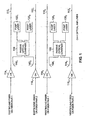
- FIG. 1 shows four unidirectional optical fiber paths that each include a rare- earth doped fiber respectively, for imparting gain to the optical signals traveling along the fiber paths.
- Fig. 1 discloses an example usefull for understanding the invention which is disclosed in Fig. 2 .
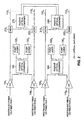
- FIG. 2 shows an embodiment of the invention.
- the present inventors have recognized that a pump sharing technique can be employed that provides redundancy to two or more pairs of optical fibers in a more reliable manner than can be achieved by the aforementioned arrangement shown in U. S. Pat. No. 5,173, 957 .
- a direction application of the conventional arrangement to two fiber pairs would require at total of four pump sources, with one pair of pump sources providing power to one fiber pair and another pair of pump sources providing power to the other fiber pair.
- a failure of two pumps supplying power to a fiber pair would result in the loss of that particular fiber pair.
- the present invention provides an arrangement in which the failure of any two pumps will not lead to the complete loss of a fiber pair. That is, at worst, the failure of two pumps will lead to the loss of only one fiber in each of the two fiber pairs, preserving the ability to carry traffic in the other fiber in each fiber pair.
- the present invention will be described in connection with a four-fiber transmission path that receives pump energy from four pump sources.
- the present invention is not limited to such an arrangement. More generally, the present example is applicable to a transmission path that employs N pairs of optical fibers with 2N optical amplifiers respectively located in each of the 2N fibers and 2N pump sources, where N is an integer greater than two.
- FIG. 1 shows four unidirectional optical fiber paths 110 1 , 110 2 , 112 1 , and 112 2 that each include a rare-earth doped fiber 114 1 , 114 2 , 116 2 , and 116 2 , respectively, for imparting gain to the optical signals traveling along the fiber paths.
- the fiber paths 110 1 , 110 2 , 112 1 , and 112 2 are arranged in two pairs, each of which support bi-directional communication.
- a first fiber pair 110 comprises unidirectional fibers 110 1 and 110 2 that support optical signals traveling in opposite directions.
- a second fiber pair 112 comprises unidirectional fibers 112 1 and 112 2 that also support optical signals traveling in opposite directions with respect to one another.
- a first pump arrangement that supplies pump energy to one fiber in each of the fiber pairs 110 and 112.
- two pump sources 120 1 and 120 2 supply pump energy to the rare-earth doped fiber 114 2 located in fiber 110 1 of the first fiber pair 110 and to rare-earth doped fiber 116 1 located in fiber 112 1 of the second fiber pair 112.
- a 2x2 combiner/splitter 150 combines the pump energy generated by the pump sources 120 1 and 120 2 and splits the combined power among the rare-earth doped fibers 114 1 and 116 1 .
- Coupling elements 140 1 and 140 2 receive the pump energy from the output ports of the 2x2 combiner/splitter 150 and respectively direct the pump energy onto the fiber paths 110 1 and 112 1 where the pump energy is combined with the signals.
- the coupling elements 140 1 and 140 2 which may be fused fiber couplers or wavelength division multiplexers, for example, are generally configured to have a high coupling ratio at the pump energy wavelength and a low coupling ratio at the signal wavelength.
- a second pump arrangement that also supplies pump energy to one fiber in each of the fiber pairs 110 and 112.
- two pump sources 130 1 and 130 2 supply pump energy to the rare-earth doped fiber 114 2 located in fiber 110 2 of the first fiber pair 110 and to rare-earth doped fiber 116 2 located in fiber 112 2 of the second fiber pair 112.
- a 2x2 combiner/splitter 160 combines the pump energy generated by the pump sources 130 1 and 130 2 and splits the combined power among the rare-earth doped fibers 114 2 and 116 2 .
- Coupling elements 144 1 and 144 2 receive the pump energy from the output ports of the 2x2 combiner/splitter 160 and respectively direct the pump energy onto the fiber paths 110 2 and 112 2 where the pump energy is combined with the signals.
- the coupling elements 144 1 and 144 2 may comprise any appropriate coupling arrangement known to those of ordinary skill in the art, including fused fiber couplers or wavelength division multiplexers, for example.
- a failure of both pump source 120 1 (or pump source 120 2 ) in the first pump arrangement and pump source 130 1 (or pump source 130 2 ) in the second pump arrangement would only reduce by half the total power supplied to the fibers 110 1 , 110 2 , 112 1 , and 112 2 , thus allowing traffic to continue along all four fibers 110 1 , 110 2 , 112 1 , and 112 2 .
- the passive coupling arrangement depicted in FIG. 2 transfers excess pump power traveling in the eastbound direction along fibers 110 1 and 112 1 so that it travels in the westbound direction along fibers 110 2 and 112 2 .
- Those of ordinary skill in the art will recognize that a similar arrangement may be employed to transfer excess pump power traveling in the westbound direction along fibers 110 2 and 112 2 to the eastbound direction along fibers 110 1 and 112 1 , so that it can be provided to erbium doped fibers 114 1 and 116 1 .
- two additional 2x2 combiner/splitters are employed along with four coupling elements, two of which are located upstream from rare-earth doped fibers 114 1 and 116 1 along fibers 110 1 and 112 2 , respectively, and two of which are located downstream from rare-earth doped fibers 114 2 and 116 2 along fibers 110 2 and 112 2 , respectively.
Landscapes
- Physics & Mathematics (AREA)
- Electromagnetism (AREA)
- Engineering & Computer Science (AREA)
- Computer Networks & Wireless Communication (AREA)
- Signal Processing (AREA)
- Lasers (AREA)
- Optical Communication System (AREA)
Description
- This application claims the benefit of priority to
U. S. Provisional Patent Application 60/404,719, filed August 20, 2002 - The present invention relates generally to optical amplifiers such as employed in optical transmission systems, and more particularly to an optical amplifier arrangement in which a failed pump source can be readily determined.
- Optical amplifiers have become an essential component in transmission systems and networks to compensate for system losses, particularly in wavelength division multiplexed (WDM) and dense wavelength division multiplexed (DWDM) communication systems. In a WDM transmission system, two or more optical data carrying channels, each defined by a different carrier wavelength, are combined onto a common path for transmission to a remote receiver. The carrier wavelengths are sufficiently separated so that they do not overlap in the frequency domain. Typically, in a long-haul optical fiber system, an optical amplifier would amplify the set of wavelength channels simultaneously, usually after traversing distances less than about 120 km.
- One class of optical amplifiers is rare-earth doped optical amplifiers, which use rare-earth ions as the active element. The ions are doped in the fiber core and pumped optically to provide gain. The silica fiber core serves as the host medium for the ions. While many different rare-earth ions such as neodymium, praseodymium, ytterbium etc. can be used to provide gain in different portions of the spectrum, erbium-doped fiber amplifiers (EDFAs) have proven to be particularly attractive because they are operable in the spectral region where optical loss in the fiber is minimal. Also, the erbium-doped fiber amplifier is particularly useful because of its ability to amplify multiple wavelength channels without crosstalk penalty, even when operating deep in gain compression. EDFAs are also attractive because they are fiber devices and thus can be easily connected to telecommunications fiber with low loss.
- An important consideration in the design of a WDM transmission system is reliability, particularly when the system is not readily accessible for repair, such as in undersea applications. Since the laser pump is the only active component in the amplification system, it is the most likely to degrade or fail. Such failure would render the optical amplifier, and possibly the optical communication system, inoperative. In order to overcome such an event, several techniques have been developed to design optical communication systems capable of limiting the impact of laser pump failure or degradation. For example, redundancy is sometimes used to obviate optical amplifier failures.
- Redundancy can be conveniently employed when two or more optical amplifiers are employed in a single location, which is often the case in a typical long- range optical transmission system that includes a pair of unidirectional optical fibers that support optical signals traveling in opposite directions. In such systems each fiber includes an optical amplifier, which are co-located in a common housing known as a repeater. When multiple amplifiers are co-located redundancy can be achieved by sharing pump energy form all the available pumps among all the amplifiers. For example, in
U. S. Pat. No. 5,173, 957 , the output from at least two pump sources are coupled via a 3 dB optical coupler to provide pump energy to each of two optical fiber amplifiers simultaneously. If one of the pump sources fails, the other pump source provides power to each of the optical amplifiers. Thus, failure of one laser pump causes a 50% reduction in the pumping power of each of the two optical amplifiers. Without such pump sharing, a pump failure could lead to catastrophic failure in one amplifier and no failures in the other. As long as some pump energy reaches each amplifier, there will be enough gain to convey the signals to the next optical amplifier. On the other hand, if any given amplifier were to lose all its pump energy, it becomes a lossy medium and attenuates the signals, usually leading to excessive signal-to-noise ratio at the end of the systems. In another example,EP 0,779,687 A2 provides a method and optical fiber amplifier arrangement including first and second independent optical fiber amplifiers each including a rare-earth doped optical fiber etc., to thereby achieve greater amplification efficiency. Similar arrangements are shown inJP 6 314 833 A - While the aforementioned pump redundancy arrangement may be satisfactory for some applications, it would be desirable to provide a pump redundancy arrangement with an even greater degree of reliability, particularly in an optical transmission system that employs multiple pairs of optical fibers.
- In accordance with the present invention, an optical repeater is provided. The repeater includes at least four optical amplifiers each supplying optical amplification to an optical signal traveling in a different unidirectional optical fiber that collectively form at least two bi-directional pairs of optical fibers. The repeater also includes a first plurality of pump sources for providing pump energy to a first optical fiber located in a first of the optical fiber pairs and a second optical fiber located in a second of the optical fiber pairs. The first optical fiber and the second optical fiber support optical signals traveling in a common direction. A first combiner arrangement combines the pump energy from the first plurality of pump sources and distributes it to the optical amplifiers supplying amplification to optical signals traveling in the first and the second optical fibers. A second plurality of pump sources provides pump energy to a third optical fiber located in the first optical fiber pair and a fourth optical fiber located in the second optical fiber pair. The third optical fiber and the fourth optical fiber support optical signals traveling in a common direction that is opposite to that of the first and second optical fibers. A second combiner arrangement combines the pump energy from the second plurality of pump sources and distributes it to the optical amplifiers supplying amplification to optical signals traveling in the third and the fourth optical fibers. A first passive coupling arrangement is provided for conveying excess pump energy that traverses the optical amplifiers in the first and the second optical fibers to the third and the fourth optical fibers at a location upstream from the optical amplifiers supplying amplification to optical signals traversing the third and the fourth optical fibers. A second passive coupling arrangement is provided for conveying excess pump energy that traverses the optical amplifiers in the third and the fourth optical fibers to the first and the second optical fibers at a location upstream from the optical amplifiers supplying amplification to optical signals traversing the first and the second optical fibers
- In accordance with another aspect of the invention, the optical amplifiers are rare-earth doped optical amplifiers.
- In accordance with another aspect of the invention, the rare-earth doped optical amplifiers are erbium-doped optical amplifiers.
- In accordance with another aspect of the invention, the first combiner arrangement includes a first combiner and a first plurality of couplers coupling pump energy from the combiner to the first and the second optical fibers.
- In accordance with another aspect of the invention, the second combiner arrangement includes a second combiner and a second plurality of couplers coupling pump energy from the second combiner to the third and the fourth optical fibers.
- In accordance with another aspect of the invention, the first and second combiners are 2x2 combiners.
-
FIG. 1 shows four unidirectional optical fiber paths that each include a rare- earth doped fiber respectively, for imparting gain to the optical signals traveling along the fiber paths.Fig. 1 discloses an example usefull for understanding the invention which is disclosed inFig. 2 . -
FIG. 2 shows an embodiment of the invention. - The present inventors have recognized that a pump sharing technique can be employed that provides redundancy to two or more pairs of optical fibers in a more reliable manner than can be achieved by the aforementioned arrangement shown in
U. S. Pat. No. 5,173, 957 . For example, a direction application of the conventional arrangement to two fiber pairs would require at total of four pump sources, with one pair of pump sources providing power to one fiber pair and another pair of pump sources providing power to the other fiber pair. In such an arrangement a failure of two pumps supplying power to a fiber pair would result in the loss of that particular fiber pair. On the other hand, as described below, the present invention provides an arrangement in which the failure of any two pumps will not lead to the complete loss of a fiber pair. That is, at worst, the failure of two pumps will lead to the loss of only one fiber in each of the two fiber pairs, preserving the ability to carry traffic in the other fiber in each fiber pair. - For purposes of illustration the present invention will be described in connection with a four-fiber transmission path that receives pump energy from four pump sources. However, the present invention is not limited to such an arrangement. More generally, the present example is applicable to a transmission path that employs N pairs of optical fibers with 2N optical amplifiers respectively located in each of the 2N fibers and 2N pump sources, where N is an integer greater than two.
-
FIG. 1 shows four unidirectionaloptical fiber paths fiber fiber paths first fiber pair 110 comprisesunidirectional fibers - In accordance with the example of
fig. 1 , a first pump arrangement is provided that supplies pump energy to one fiber in each of the fiber pairs 110 and 112. In particular, two pump sources 1201 and 1202 supply pump energy to the rare-earth dopedfiber 1142 located infiber 1101 of thefirst fiber pair 110 and to rare-earth doped fiber 1161 located in fiber 1121 of the second fiber pair 112. A 2x2 combiner/splitter 150 combines the pump energy generated by the pump sources 1201 and 1202 and splits the combined power among the rare-earth dopedfibers 1141 and 1161. Couplingelements splitter 150 and respectively direct the pump energy onto thefiber paths 1101 and 1121 where the pump energy is combined with the signals. Thecoupling elements - Similar to the first pump arrangement, a second pump arrangement is provided that also supplies pump energy to one fiber in each of the fiber pairs 110 and 112. In particular, two
pump sources fiber 1142 located infiber 1102 of thefirst fiber pair 110 and to rare-earth doped fiber 1162 located in fiber 1122 of the second fiber pair 112. A 2x2 combiner/splitter 160 combines the pump energy generated by thepump sources fibers 1142 and 1162. Coupling elements 1441 and 1442 receive the pump energy from the output ports of the 2x2 combiner/splitter 160 and respectively direct the pump energy onto thefiber paths 1102 and 1122 where the pump energy is combined with the signals. Like couplingelements - Because in the example of
fig. 1 each pump arrangement provides power to fibers located in a different fiber pair, the failure of any two pumps will still allow traffic to be carried in one direction along each of the two fiber pairs. For example, referring toFIG. 1 , a failure of both pumps sources 1201 and 1202 will lead to the loss of traffic inoptical fibers 1101 and 1121 of thefirst fiber pair 110 and the second fiber pair 112, respectively. Traffic inoptical fiber 1102 of thefirst fiber pair 110 and optical fiber 1122 of the second fiber pair will be unaffected. On the other hand, however, if two pumps were to fail, with each pump located in a different one of the pump arrangements, traffic on none of the fibers would be lost. For example, a failure of both pump source 1201 (or pump source 1202) in the first pump arrangement and pump source 1301 (or pump source 1302) in the second pump arrangement would only reduce by half the total power supplied to thefibers fibers -
FIG. 2 shows an embodiment of the invention that provides for a higher degree of redundancy that the pumping arrangement shown inFIG. 1 . InFIGS. 1 and2 , like elements are indicated by like reference numerals. In this embodiment of the invention excess or unused co-propagating pump power that traverses rare-earth dopedfibers 1141 and 1161 and continues downstream (e. g. , in the eastbound direction) alongfibers 1101 and 1121 is transferred tofibers 1102 and 1122, where the excess power travels downstream (e. g. in the westbound direction) to co-pump rare-earth dopedfibers 1142 and 1162. This transfer or recycling of pump power is achieved by a passive coupling arrangement that includescoupling elements splitters - As shown,
coupling elements 2101 and 2201 are respectively located infiber 1101 of thefirst fiber pair 110 and fiber 1121 of the second fiber pair 112. Couplingelements 2101 and 2201 are located downstream from rare-earth dopedfibers 1141 and 1161, respectively. In addition,coupling elements 2102 and 2202 are respectively located infiber 1102 of the first fiber pair and fiber 1122 of the second fiber pair 112. Couplingelements 2102 and 2202 are located upstream from rare-earth dopedfibers 1142 and 1162, respectively. - In operation, 2x2 combiner/
splitter 270 receives excess pump energy fromcouplers 2101 and 2201 and outputs a portion of the combined pump power to each input of 2x2 combiner/splitter 280. Combine/splitter 280, in turn, combines and splits the power received on its inputs and directs each portion of the split power tocoupling elements 2102 and 2202. In this way the excess pump power is conveyed tofibers 1102 and 1122 so that it can travel downstream to rare-earth dopedfibers 1142 and 1162. - The passive coupling arrangement depicted in
FIG. 2 transfers excess pump power traveling in the eastbound direction alongfibers 1101 and 1121 so that it travels in the westbound direction alongfibers 1102 and 1122. Those of ordinary skill in the art will recognize that a similar arrangement may be employed to transfer excess pump power traveling in the westbound direction alongfibers 1102 and 1122 to the eastbound direction alongfibers 1101 and 1121, so that it can be provided to erbium dopedfibers 1141 and 1161. In this case two additional 2x2 combiner/splitters are employed along with four coupling elements, two of which are located upstream from rare-earth dopedfibers 1141 and 1161 alongfibers 1101 and 1122, respectively, and two of which are located downstream from rare-earth dopedfibers 1142 and 1162 alongfibers 1102 and 1122, respectively. - By using the aforementioned arrangement in which excess pump power is transferred from the eastbound to the westbound direction, as well as from the westbound to the eastbound direction, if any three of the
pump sources
Claims (6)
- An optical repeater, comprising:at least four optical amplifiers (1141, 1142, 1161, 1162) each supplying optical amplification to an optical signal traveling in a different unidirectional optical fiber that together form at least two bi-directional pairs of optical fibers (1101, 1102, 1121, 1122);a first plurality of pump sources (1201, 1202) for providing pump energy to a first optical fiber (1101) located in a first of the optical fiber pairs (1101, 1102) and a second optical fiber (1121) located in a second of the optical fiber pairs (1121, 1122), said first optical fiber (1101) and said second optical fiber (1121) supporting optical signals traveling in a common direction;a first combiner arrangement (150) combining the pump energy from the first plurality of pump sources (1201, 1202) and distributing it to the optical amplifiers (1141, 1161) supplying amplification to optical signals traveling in the first and the second optical fibers (1101, 1121);a second plurality of pump sources (1301, 1302) for providing pump energy to a third optical fiber (1102) located in said first optical fiber pair (1101, 1102) and a fourth optical fiber (1122) located in said second optical fiber pair (1121, 1122), said third optical fiber (1102) and said fourth optical fiber (1122) supporting optical signals traveling in a common direction that is opposite to that of said first and second optical fibers (1101, 1121);a second combiner arrangement (160) combining the pump energy from the second plurality of pump sources (1301, 1302) and distributing it to the optical amplifiers (1142, 1162) supplying amplification to optical signals traveling in the third and the fourth optical fibers (1102, 1122);Characterized in that said optical repeater further comprises:a first passive coupling arrangement (270) configured to direct unused pump energy from the optical amplifiers (1141, 1161) in said first and said second optical fibres (1101, 1121) to the optical amplifiers (1142, 1162) in said third and said fourth optical fibres (1102, 1122), the unused pump energy counter-propagating with respect to the said pump energy supplied to said optical amplifiers (1142, 1162) in said third and said fourth optical fibres (1102, 1122); anda second passive coupling arrangement (280) configured to direct unused pump energy from the optical amplifiers (1142, 1162) in said third and said fourth optical fibres (1102, 1122) to the optical amplifiers (1141, 1161) in said first and said second optical fibres (1101, 1121), the unused pump energy counter-propagating with respect to the said pump energy supplied to said optical amplifiers (1141, 1161) in said first and said second optical fibres (1101, 1121).
- The optical repeater of claim 1 wherein said optical amplifiers (1141, 1142, 1161, 1162) are rare- earth doped optical amplifiers.
- The optical repeater of claim 2 wherein said rare-earth doped optical amplifiers are erbium-doped optical amplifiers.
- The optical repeater of claim 1 wherein said first combiner arrangement includes a first combiner (150) and a first plurality of couplers (1401, 1402) coupling pump energy from said combiner (150) to the first and the second optical fibers (1101, 1121).
- The optical repeater of claim 4 wherein said second combiner arrangement includes a second combiner (160) and a second plurality of couplers (1441, 1442) coupling pump energy from said second combiner (160) to the third and the fourth optical fibers (1102, 1122),
- The optical repeater of claim 5 wherein said first and second combiners (150, 160) are 2x2 combiners.
Applications Claiming Priority (3)
| Application Number | Priority Date | Filing Date | Title |
|---|---|---|---|
| US40471902P | 2002-08-20 | 2002-08-20 | |
| US404719P | 2002-08-20 | ||
| PCT/US2003/026106 WO2004019458A2 (en) | 2002-08-20 | 2003-08-20 | Sharing pump energy among different fiber pairs |
Publications (3)
| Publication Number | Publication Date |
|---|---|
| EP1535411A2 EP1535411A2 (en) | 2005-06-01 |
| EP1535411A4 EP1535411A4 (en) | 2006-02-01 |
| EP1535411B1 true EP1535411B1 (en) | 2013-10-16 |
Family
ID=31946750
Family Applications (1)
| Application Number | Title | Priority Date | Filing Date |
|---|---|---|---|
| EP03749086.9A Expired - Lifetime EP1535411B1 (en) | 2002-08-20 | 2003-08-20 | Method and apparatus for sharing pump energy from a single pump arrangement to optical fibers located in different fiber pairs |
Country Status (8)
| Country | Link |
|---|---|
| US (1) | US6930825B2 (en) |
| EP (1) | EP1535411B1 (en) |
| JP (1) | JP4798997B2 (en) |
| CN (1) | CN100512057C (en) |
| AU (1) | AU2003268137A1 (en) |
| CA (1) | CA2496310A1 (en) |
| NO (1) | NO20051449L (en) |
| WO (1) | WO2004019458A2 (en) |
Families Citing this family (12)
| Publication number | Priority date | Publication date | Assignee | Title |
|---|---|---|---|---|
| JP4122884B2 (en) * | 2002-07-30 | 2008-07-23 | 日本電気株式会社 | Optical repeater |
| US20060140633A1 (en) * | 2004-12-28 | 2006-06-29 | Sanmina-Sci Corporation | Systems and methods for optical pump redundancy |
| US20060251423A1 (en) * | 2005-05-09 | 2006-11-09 | Evangelides Stephen G Jr | Method and apparatus for identifying pump failures using an optical line interface |
| CN105529604A (en) * | 2016-02-26 | 2016-04-27 | 昂纳信息技术(深圳)有限公司 | Pump-sharing optical fiber amplifier |
| US10812880B2 (en) | 2016-03-22 | 2020-10-20 | Lyteloop Technologies, Llc | Data in motion storage system and method |
| CN109390839B (en) * | 2017-08-11 | 2021-08-27 | 珠海保税区光联通讯技术有限公司 | Optical module and erbium-doped fiber amplifier |
| AU2019312672A1 (en) | 2018-08-02 | 2021-03-18 | Nkb Properties Management, Llc | Apparatus and method for storing wave signals in a cavity |
| BR112020018431B1 (en) | 2018-08-10 | 2021-08-10 | Lyteloop Technologies, Llc | SYSTEM AND METHOD FOR EXTENDING TRAJECTORY LENGTH OF A WAVE SIGNAL USING ANGLE MULTIPLEXATION |
| WO2020041931A1 (en) * | 2018-08-27 | 2020-03-05 | 华为海洋网络有限公司 | Submarine network device |
| JP7127694B2 (en) * | 2018-10-18 | 2022-08-30 | 日本電気株式会社 | Optical repeater and optical signal relay method |
| CN109327261B (en) * | 2018-10-18 | 2021-05-11 | 武汉光迅电子技术有限公司 | Optical path structure of an optical repeater |
| MX2021002558A (en) | 2018-11-05 | 2021-04-29 | Lyteloop Tech Llc | Systems and methods for building, operating and controlling multiple amplifiers, regenerators and transceivers using shared common components. |
Citations (3)
| Publication number | Priority date | Publication date | Assignee | Title |
|---|---|---|---|---|
| US5241414A (en) * | 1992-08-21 | 1993-08-31 | At&T Bell Laboratories | Fault tolerant optical amplifier arrangement |
| JPH06314833A (en) * | 1993-04-28 | 1994-11-08 | Nec Corp | Two-way excitation light amplifier |
| US20020057477A1 (en) * | 2000-10-25 | 2002-05-16 | Corrado Rocca | Underwater optical transmission system and switchable underwater repeater |
Family Cites Families (7)
| Publication number | Priority date | Publication date | Assignee | Title |
|---|---|---|---|---|
| DK220690A (en) * | 1990-09-14 | 1992-03-15 | Nordiske Kabel Traad | OPTICAL FIBER AMPLIFIER WITH CONNECTION OF PUMP ENERGY FROM MULTIPLE PUMP SOURCES |
| US5173957A (en) | 1991-09-12 | 1992-12-22 | At&T Bell Laboratories | Pump redundancy for optical amplifiers |
| JP2928149B2 (en) | 1995-12-14 | 1999-08-03 | 日本電気株式会社 | Optical fiber amplifier |
| US5801858A (en) | 1996-06-25 | 1998-09-01 | Northern Telecom Limited | Optical transmission systems using optical amplifiers and wavelength division multiplexing |
| US5815613A (en) * | 1996-12-31 | 1998-09-29 | Lucent Technologies Inc. | Optical switched distributor |
| US6236777B1 (en) * | 1997-05-13 | 2001-05-22 | Pirelli Cavi E Sistemi S.P.A. | Reliability of an optical communication system and of an optical amplifying system, and a method suitable to this aim |
| JP4626918B2 (en) * | 2001-03-02 | 2011-02-09 | 富士通株式会社 | Raman optical repeater |
-
2003
- 2003-08-20 EP EP03749086.9A patent/EP1535411B1/en not_active Expired - Lifetime
- 2003-08-20 AU AU2003268137A patent/AU2003268137A1/en not_active Abandoned
- 2003-08-20 US US10/646,351 patent/US6930825B2/en not_active Expired - Lifetime
- 2003-08-20 WO PCT/US2003/026106 patent/WO2004019458A2/en not_active Ceased
- 2003-08-20 CN CNB038222329A patent/CN100512057C/en not_active Expired - Lifetime
- 2003-08-20 CA CA002496310A patent/CA2496310A1/en not_active Abandoned
- 2003-08-20 JP JP2004531148A patent/JP4798997B2/en not_active Expired - Fee Related
-
2005
- 2005-03-18 NO NO20051449A patent/NO20051449L/en not_active Application Discontinuation
Patent Citations (3)
| Publication number | Priority date | Publication date | Assignee | Title |
|---|---|---|---|---|
| US5241414A (en) * | 1992-08-21 | 1993-08-31 | At&T Bell Laboratories | Fault tolerant optical amplifier arrangement |
| JPH06314833A (en) * | 1993-04-28 | 1994-11-08 | Nec Corp | Two-way excitation light amplifier |
| US20020057477A1 (en) * | 2000-10-25 | 2002-05-16 | Corrado Rocca | Underwater optical transmission system and switchable underwater repeater |
Also Published As
| Publication number | Publication date |
|---|---|
| WO2004019458A3 (en) | 2005-04-07 |
| AU2003268137A1 (en) | 2004-03-11 |
| EP1535411A4 (en) | 2006-02-01 |
| AU2003268137A8 (en) | 2004-03-11 |
| NO20051449L (en) | 2005-05-19 |
| EP1535411A2 (en) | 2005-06-01 |
| JP2005536892A (en) | 2005-12-02 |
| US20040136056A1 (en) | 2004-07-15 |
| CA2496310A1 (en) | 2004-03-04 |
| CN1682471A (en) | 2005-10-12 |
| CN100512057C (en) | 2009-07-08 |
| US6930825B2 (en) | 2005-08-16 |
| WO2004019458A2 (en) | 2004-03-04 |
| JP4798997B2 (en) | 2011-10-19 |
| WO2004019458A9 (en) | 2004-05-06 |
Similar Documents
| Publication | Publication Date | Title |
|---|---|---|
| US6052219A (en) | Wide bandwidth Raman amplifier capable of employing pump energy spectrally overlapping the signal | |
| EP0532230B1 (en) | Optical amplifiers having pump redundancy | |
| US6941074B2 (en) | Bidirectionally transmittable optical wavelength division multiplexed transmission system | |
| US12597752B2 (en) | Gain equalization in C+L erbium-doped fiber amplifiers | |
| WO1995024065A1 (en) | Unidirectional amplification for bi-directional transmission using wavelength-division multiplexing | |
| US6930825B2 (en) | Method and apparatus for sharing pump energy from a single pump arrangement to optical fibers located in different fiber pairs | |
| US6359728B1 (en) | Pump device for pumping an active fiber of an optical amplifier and corresponding optical amplifier | |
| US6236777B1 (en) | Reliability of an optical communication system and of an optical amplifying system, and a method suitable to this aim | |
| US8233216B2 (en) | Optical amplifier bandwidth alteration | |
| US11362753B2 (en) | Optical node device | |
| US20060140633A1 (en) | Systems and methods for optical pump redundancy | |
| US20040207912A1 (en) | Method and apparatus for distributing pump energy to an optical amplifier array in an asymmetric manner | |
| JP4095159B2 (en) | Optical communication system and optical amplification system | |
| US20040184816A1 (en) | Multiwavelength depolarized Raman pumps | |
| US6901190B1 (en) | Fault tolerant optical amplifier configuration using pump feedthrough | |
| US7145716B2 (en) | Multiple stage Raman optical amplifier | |
| US6980357B2 (en) | Optical amplifier apparatus and method | |
| US20240055823A1 (en) | Light supply apparatus | |
| EP0878927B1 (en) | Improvement in the reliability of an optical communication system and a method suitable to this aim | |
| EP1573869A1 (en) | Multiple stage raman optical amplifier | |
| WO1998052305A1 (en) | Redundant optical power supply for remote pumping of fiber optic gain modules | |
| JPWO2018168593A1 (en) | Optical amplification module and optical amplification method |
Legal Events
| Date | Code | Title | Description |
|---|---|---|---|
| PUAI | Public reference made under article 153(3) epc to a published international application that has entered the european phase |
Free format text: ORIGINAL CODE: 0009012 |
|
| 17P | Request for examination filed |
Effective date: 20050317 |
|
| AK | Designated contracting states |
Kind code of ref document: A2 Designated state(s): AT BE BG CH CY CZ DE DK EE ES FI FR GB GR HU IE IT LI LU MC NL PT RO SE SI SK TR |
|
| AX | Request for extension of the european patent |
Extension state: AL LT LV MK |
|
| DAX | Request for extension of the european patent (deleted) | ||
| RBV | Designated contracting states (corrected) |
Designated state(s): DE FR GB |
|
| A4 | Supplementary search report drawn up and despatched |
Effective date: 20051220 |
|
| RIC1 | Information provided on ipc code assigned before grant |
Ipc: H04B 10/12 20060101AFI20050414BHEP Ipc: H01S 3/094 20060101ALI20051214BHEP Ipc: H04B 10/17 20060101ALI20051214BHEP |
|
| RAP1 | Party data changed (applicant data changed or rights of an application transferred) |
Owner name: RED SKY SUBSEA LTD |
|
| 17Q | First examination report despatched |
Effective date: 20081103 |
|
| RAP1 | Party data changed (applicant data changed or rights of an application transferred) |
Owner name: HUAWEI MARINE NETWORKS CO., LIMITED |
|
| REG | Reference to a national code |
Ref country code: DE Ref legal event code: R079 Ref document number: 60345094 Country of ref document: DE Free format text: PREVIOUS MAIN CLASS: H04B0010120000 Ipc: H04B0010250000 |
|
| GRAP | Despatch of communication of intention to grant a patent |
Free format text: ORIGINAL CODE: EPIDOSNIGR1 |
|
| INTG | Intention to grant announced |
Effective date: 20130412 |
|
| RIC1 | Information provided on ipc code assigned before grant |
Ipc: H01S 3/094 20060101ALI20130409BHEP Ipc: H04B 10/25 20130101AFI20130409BHEP Ipc: H04B 10/291 20130101ALI20130409BHEP |
|
| GRAS | Grant fee paid |
Free format text: ORIGINAL CODE: EPIDOSNIGR3 |
|
| GRAA | (expected) grant |
Free format text: ORIGINAL CODE: 0009210 |
|
| AK | Designated contracting states |
Kind code of ref document: B1 Designated state(s): DE FR GB |
|
| REG | Reference to a national code |
Ref country code: GB Ref legal event code: FG4D |
|
| REG | Reference to a national code |
Ref country code: DE Ref legal event code: R096 Ref document number: 60345094 Country of ref document: DE Effective date: 20131212 |
|
| REG | Reference to a national code |
Ref country code: DE Ref legal event code: R097 Ref document number: 60345094 Country of ref document: DE |
|
| PLBE | No opposition filed within time limit |
Free format text: ORIGINAL CODE: 0009261 |
|
| STAA | Information on the status of an ep patent application or granted ep patent |
Free format text: STATUS: NO OPPOSITION FILED WITHIN TIME LIMIT |
|
| 26N | No opposition filed |
Effective date: 20140717 |
|
| REG | Reference to a national code |
Ref country code: DE Ref legal event code: R097 Ref document number: 60345094 Country of ref document: DE Effective date: 20140717 |
|
| REG | Reference to a national code |
Ref country code: FR Ref legal event code: PLFP Year of fee payment: 14 |
|
| REG | Reference to a national code |
Ref country code: FR Ref legal event code: PLFP Year of fee payment: 15 |
|
| REG | Reference to a national code |
Ref country code: FR Ref legal event code: PLFP Year of fee payment: 16 |
|
| PGFP | Annual fee paid to national office [announced via postgrant information from national office to epo] |
Ref country code: FR Payment date: 20210812 Year of fee payment: 19 |
|
| PGFP | Annual fee paid to national office [announced via postgrant information from national office to epo] |
Ref country code: GB Payment date: 20210728 Year of fee payment: 19 Ref country code: DE Payment date: 20210727 Year of fee payment: 19 |
|
| REG | Reference to a national code |
Ref country code: DE Ref legal event code: R119 Ref document number: 60345094 Country of ref document: DE |
|
| GBPC | Gb: european patent ceased through non-payment of renewal fee |
Effective date: 20220820 |
|
| PG25 | Lapsed in a contracting state [announced via postgrant information from national office to epo] |
Ref country code: FR Free format text: LAPSE BECAUSE OF NON-PAYMENT OF DUE FEES Effective date: 20220831 Ref country code: DE Free format text: LAPSE BECAUSE OF NON-PAYMENT OF DUE FEES Effective date: 20230301 |
|
| PG25 | Lapsed in a contracting state [announced via postgrant information from national office to epo] |
Ref country code: GB Free format text: LAPSE BECAUSE OF NON-PAYMENT OF DUE FEES Effective date: 20220820 |