EP1534027A2 - Wireless distributed base station - Google Patents
Wireless distributed base station Download PDFInfo
- Publication number
- EP1534027A2 EP1534027A2 EP04256857A EP04256857A EP1534027A2 EP 1534027 A2 EP1534027 A2 EP 1534027A2 EP 04256857 A EP04256857 A EP 04256857A EP 04256857 A EP04256857 A EP 04256857A EP 1534027 A2 EP1534027 A2 EP 1534027A2
- Authority
- EP
- European Patent Office
- Prior art keywords
- wireless
- radio frequency
- base band
- radio
- antenna
- Prior art date
- Legal status (The legal status is an assumption and is not a legal conclusion. Google has not performed a legal analysis and makes no representation as to the accuracy of the status listed.)
- Withdrawn
Links
Images


Classifications
-
- H—ELECTRICITY
- H04—ELECTRIC COMMUNICATION TECHNIQUE
- H04W—WIRELESS COMMUNICATION NETWORKS
- H04W88/00—Devices specially adapted for wireless communication networks, e.g. terminals, base stations or access point devices
- H04W88/08—Access point devices
- H04W88/085—Access point devices with remote components
-
- H—ELECTRICITY
- H04—ELECTRIC COMMUNICATION TECHNIQUE
- H04B—TRANSMISSION
- H04B7/00—Radio transmission systems, i.e. using radiation field
- H04B7/14—Relay systems
- H04B7/15—Active relay systems
- H04B7/155—Ground-based stations
Definitions
- the present invention relates generally to communications and, more particularly, to a wireless communications systems.
- Wireless communications systems provide wireless service to a number of wireless or mobile units situated within a geographic region.
- the geographic region supported by a wireless communications system is divided into spatially distinct areas commonly referred to as "cells.”
- Each cell ideally, may be represented by a hexagon in a honeycomb pattern. In practice, however, each cell may have an irregular shape, depending on various factors including the topography of the terrain surrounding the cell.
- each cell is further broken into two or more sectors. Each cell is commonly divided into three sectors, each having a range of 120 degrees, for example.
- a conventional cellular system comprises a number of cell sites or base transceiver stations geographically distributed to support the transmission and reception of communication signals to and from the wireless or mobile units.
- Each cell site handles communications within, as well as outside the cell.
- the overall coverage area for the cellular system may be defined by the union of cells for all of the cell sites, where the coverage areas for nearby cell sites overlap to ensure, where possible, contiguous communication coverage within the outer boundaries of the system's coverage area.
- a wireless unit When active, a wireless unit receives signals from at least one base station over a forward link (e.g., downlink) and transmits signals to at least one base station over a reverse link (e.g., uplink).
- a forward link e.g., downlink
- a reverse link e.g., uplink
- TDMA time-division multiple access
- CDMA code-division multiple access
- OFDMA orthogonal-frequency division multiple access
- Each base transceiver station typically comprises one or more radio towers and one or more antennas for communicating with each of the wireless units in that cell. Moreover, each base transceiver station includes transmission equipment for communicating with a mobile switching center ("MSC”).
- MSC mobile switching center
- a mobile switching center is responsible for, among other things, establishing and maintaining calls between the wireless units, between a wireless unit and a wireline unit through a public switched telephone network (“PSTN”), as well as between a wireless unit and a packet data network (“PDN”), such as the Internet.
- PSTN public switched telephone network
- PDN packet data network
- a base station controller administers the radio resources for one or more base transceiver stations and relays this information to the MSC.
- each base transceiver station comprises at least one radio frequency unit ("RFU").
- each RFU includes at least one radio for communicating with mobile telephones over the air interface.
- the transmission equipment also comprises at least one base band unit (“BBU").
- Each BBU may include one or more processors for handling communication between the RFU and the mobile switching center, as well as channel cards.
- each BBU in the base transceiver station is coupled via a dedicated hardline, such as a fiber optic or coaxial cable, to the mobile switching center.
- a dedicated hardline such as a fiber optic or coaxial cable
- the RFUs are placed in multiple locations to form the cells, the BBUs are separated from the RFUs they serve, thus forming a distributed system.
- several base band subsystems may be located in a central area, with each base band subsystem using a dedicated link to its respective RFU via a point-to-point optical fiber or coaxial cable.
- This hard connection between BBU and RFU is labor intensive and expensive to complete, requiring special service workers to lay down the fiber optic or coaxial cable between the BBU and RFU.
- the topography of the location (e.g., mountain range) of the base transceiver station may also lend itself to spacing the BBU and RFU apart at even significant distances in order to improve performance. This spacing between the BBU and RFU may add significant cost to the base transceiver station.
- the real estate between the BBU and RFU, for example, may require a lease or a deed for the right to lay down the fiber optic or coaxial cable.
- the present invention provides for a base transceiver station with enhanced flexibility.
- the base transceiver station may provide an increasingly cost-effective approach by, for example, reducing and/or eliminating the need for laying down external and/or internal fiber optic or coaxial cable between components, such as the BBU and RFU.
- the present invention may also provides a simpler configuration by, for example, reducing and/or eliminating the need for a lease, deed or legal right to lay down the fiber optic cable between components such as the BBU and RFU, for example.
- a base transceiver station of the present invention includes at least one base band unit and at least one radio frequency unit.
- the base transceiver station also includes a wireless link for coupling the baseband unit with the radio frequency unit.
- the baseband and radio frequency units may be spaced, in one example, at a distance of about 500 meters.
- the base band unit(s) may comprise a multi-headed air interface antenna (e.g., one or more antenna heads per sector).
- the multi-headed air interface antenna may be tuned to support a data rate of at least 100 Mbps, and may comprise wideband and/or narrowband characteristics.
- the radio frequency unit(s) may comprise an RF antenna for supporting the wireless link.
- the RF antenna may be tuned to support a data rate of at least 100 Mbps and also may comprise wideband and/or narrowband characteristics.
- a base transceiver station may include a base band unit(s) and a radio frequency unit(s).
- the base band unit(s) may comprise at least two base band unit printed circuit boards and a base band unit wireless link for coupling the base band unit printed circuit boards to each other.
- the base band unit wireless link may comprise a range of at least 10 feet and may support a data rate of at least 100 Mbps.
- the radio frequency unit(s) may comprises at least two radio frequency unit printed circuit boards and a radio frequency wireless link for coupling the radio frequency unit printed circuit boards to each other.
- the radio frequency wireless link may comprise a range of at least 10 feet and operate at a frequency range of at least 100 Mbps.
- the present invention provides for a base transceiver station with enhanced flexibility.
- the base transceiver station may provide an increasingly cost-effective approach by, for example, reducing and/or eliminating the need for laying down external and/or internal fiber optic or coaxial cable between components, such as the BBU and RFU.
- the present invention may also provides a simpler configuration by, for example, reducing and/or eliminating the need for a lease, deed or legal right to lay down the fiber optic cable between components such as the BBU and RFU, for example.
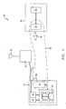
- Wireless transceiver 10 is shown having a distributed architecture.
- Wireless transceiver 10 may be realized by a base transceiver station.
- Wireless transceiver 10 comprises at least one radio tower 20 . Moreover, wireless transceiver 10 comprises one or more antennas 30 for communicating with each wireless unit in the cell. Each wireless transceiver 10 includes transmission equipment for communicating with a mobile switching center (not shown).
- wireless transceiver 10 may designed in accordance with a distributed architecture. This distribution may take into account the topography and/or landscape of the location of transceiver 10 . Cell coverage, moreover, may also be enhanced by means of the distributing architecture of transceiver 10 .
- the transmission equipment includes, for example, one or more radio frequency units ("RFUs") 40 coupled with tower 20 by means of a cable 35 .
- Each RFU comprises a power amplifier 44 and a filter 48 .
- each RFU 40 includes one or more radios 50 .
- Radio 50 performs various functions, including for communicating with mobile telephones over the air interface.
- each radio 50 comprises an intermediate frequency (“IF") section 52, an in-phase and quadrature (“I&Q”) section 54, a radio frequency (“RF”) section 56 and a digital section 58.
- IF intermediate frequency
- I&Q in-phase and quadrature
- RF radio frequency
- the transmission equipment of wireless transceiver 10 also comprises at least one base band unit ("BBU") 60 .
- Each BBU 60 includes one or more processors 65 for handling communication between the RFU and the mobile switching center.
- the connection between RFU 40 and the mobile switching center through BBU 60 is realized by means of cabling.
- components of the transmission equipment, generally, and more particularly, components of RFU 40 may be distributed.
- wireless transceiver 10 comprises a wireless link 70 for wirelessly coupling BBU 60 with RFU 40 .
- Wireless link 70 enables BBU 60 with RFU 40 to be spaced at 500 meters or less from each to take advantage of the terrain, topography and/or landscape of the location of transceiver 10 .
- BBU 60 may be wireless coupled through wireless link 70 with one or more radios 50 of RFU 40. More particularly, BBU 60 may be wirelessly coupled with one or more sub-components of radio 50 - e.g., BBU 60 may be wirelessly coupled with IF section 52, I&Q section 54, RF section 56 and/or digital section 58. To simplify the architecture, amplifier 44 and 48 may be likely collocated with any one or more of the sub-components of radio 50 .
- wireless link 70 may necessitate additional hardware and/or software to insure proper and secure wireless communication occurs between BBU 60 and radio 50 of RFU 40.
- radio 50 comprises a transmitter-receiver 74
- BBU 60 also comprises a transmitter-receiver 78 .
- Each transmitter-receiver, 74 and 78 comprises either a line-of-sight transceiver (e.g., operating at frequency of about 4 GHz) and/or a broadcast transceiver (e.g., operating at a frequency of at least 100 MHz).
- Each transmitter-receiver, 74 and 78 coupled with either an additional antenna (not shown) or utilizing the existing antenna structure for the general purpose of the wireless transceiver 10 , thereby enabling wireless signals to flow between BBU 60 and radio 50 of RFU 40.
- the wireless signals transmitted and received by BBU 60 and radio 50 may be identical in content to those that might be communicated in known non-distributed architectures. However, differences may include security, redundancy and error correction because of the reliance on transmission and reception over the air.
- each transmitter-receiver, 74 and 78 may also comprise various additional components.
- each transmitter-receiver, 74 and 78 may include a demultiplexer for demultiplexing an incoming received signal, an authenticator for authenticating the incoming received signal and a decryptor for decrypting the received signal.
- each transmitter-receiver, 74 and 78 may also comprise a multiplexer for multiplexing a signal to be transmitted, a deauthenticator for deauthenticating the signal to be transmitted, and an encryptor for encrypting the signal to be transmitted.
- RFU 40 and BBU 60 of wireless transceiver 10 each also may comprise an additional antenna element.
- Each radio 50 may comprise an RF antenna 80 for supporting wireless link 70 .
- RF antenna 80 in conjunction with each transmitter-receiver 74 support a data rate through the wireless link of at least 100 Mbps.
- each BBU 60 may comprise at least one multi-headed air interface antenna 90 for supporting wireless link 70 .
- the multi-headed air interface antenna may have at least one antenna head designated per sector of a cell.
- the multi-headed air interface antenna 90 in conjunction with each transmitter-receiver 78 of BBU 60 may support, in one example, a data rate through the wireless link of about 100 Mbps.
- a wireless base transceiver station 100 is shown having a distributed architecture.
- Base transceiver station 100 employs a distributed architecture to circumvent the need for legal rights to lay down the fiber optic cable, much like wireless transceiver 10 of FIG. 1. As stated hereinabove, this distribution may take into account the topography and/or landscape of the location of base transceiver station 100 . Cell coverage, moreover, may also be enhanced by means of the distributing architecture for transceiver 100 .
- the transmission equipment includes, for example, a first and a second radio frequency sub-units 140 and 145 forming an RFU.
- first RFU 140 is coupled with tower 120 by means of a cable 135 and incorporates a power amplifier 144 and a filter 148.
- Base transceiver station 100 has a distributed radio architecture. More particularly, base transceiver station 100 comprises a first and a second radio frequency sub-units, 140 and 145. Within each radio frequency sub-unit, sections of the radio architecture are incorporated. Consequently, radio frequency sub-unit 140 includes a first radio segment 150 having an IF section 152 and an I&Q section 154, while RFU includes a second radio segment 151 comprising an RF section 156 and a digital section 158. First and second radio frequency sub-units, 140 and 145, are wirelessly coupled with each other by means of transmitter-receivers, 174 and 176 , and antennas, 180 and 185 . By this arrangement, first and second radio frequency sub-units, 140 and 145, and thusly, radios 150 and 151 may be spaced from each other to take advantage of the terrain and topography of the location where base transceiver station 100 is to be situated.
- a wireless base transceiver station 200 is shown having a distributed architecture.
- Base transceiver station 200 employs a distributed architecture to circumvent the need for legal rights to lay down the fiber optic cable, much like wireless transceiver 10 of FIG. 1 and base transceiver station 100 of FIG. 2 .
- the transmission equipment includes, for example, a radio frequency unit (“RFUs”) 240 wirelessly coupled with a base band unit (“BBU”) 260 by means of a wireless link 270 .
- RFU 240 comprises a transmitter-receiver 274 and an antenna 280
- BBU includes a transmitter-receiver 278 and antenna 290 .
- transceiver station 200 also employ an internal distributed design. More particularly, RFU 240 comprises a number sub-components that wirelessly coupled to one another, aside from power amplifier 244 and a filter 248 . In place of an expensive, relatively heavy and sizeable backplane for mechanically coupling printed circuit boards together, the elements forming the radio in RFU 240 may be physically separated from each other, relying on wireless links. Consequently, an IF section 252 , an I&Q section 254 , an RF section 256 and a digital section 258 forming RFU 240 may communicate with each other and transmitter-receiver 274 via an RFU internal wireless link in place of a hard-wired cable.
- RFU 240 may have greater flexibility, and may take advantage of the terrain, topography and/or landscape of the location of base transceiver station 200 .
- the architecture of RFU 240 may support expansion by the inclusion of new and/or additional components that may be coupled to existing components through the RFU internal wireless link.
- BBU 260 may be physically separated from each other by relying on wireless links for coupling each together. Consequently, processor 265 for handling communication between the RFU and the mobile switching center may be wirelessly coupled with transmitter-receiver 278 via a BBU internal wireless link in place of a hard-wired cable.
- the layout and configuration of BBU 260 may have greater flexibility, and may take advantage of the terrain, topography and/or landscape of the location of base transceiver station 200 . It should be noted that by this design, the architecture of BBU 260 supports expansion by the inclusion of new and/or additional components that may be coupled to existing components through the BBU internal wireless link.
Landscapes
- Engineering & Computer Science (AREA)
- Computer Networks & Wireless Communication (AREA)
- Signal Processing (AREA)
- Mobile Radio Communication Systems (AREA)
- Support Of Aerials (AREA)
Abstract
Description
Claims (10)
- A wireless transceiver comprising:at least one base band unit;at least one radio frequency unit having at least one radio; anda wireless link for wirelessly coupling the at least one baseband unit with the at least one radio.
- The wireless transceiver of Claim 1, wherein at least one of the base band unit and the radio frequency unit comprises a transmitter-receiver for supporting the wireless link.
- The wireless transceiver of Claim 2, wherein the transmitter-receiver comprises at least one of a line-of-sight transceiver and a broadcast transceiver.
- The wireless transceiver of Claim 2, wherein the radio comprises at least one of:a demultiplexer for demultiplexing a received signal and a multiplexer for multiplexing a signal to be transmitted;an authenticator for authenticating the received signal and an deauthenticator for deauthenticating the signal to be transmitted; anda decryptor for decrypting the received signal and an encryptor for encrypting the signal to be transmitted.
- The wireless transceiver of Claim 2, wherein the at least one base band unit comprises a multi-headed air interface antenna for supporting the wireless link.
- The wireless transceiver of Claim 5, wherein the multi-headed air interface antenna comprises at least one antenna head per sector operative to support a data rate of at least 100 Mbps.
- The wireless transceiver of Claim 5, wherein the at least one radio comprises an RF antenna for supporting the wireless link, the RF antenna operative to support a data rate of at least 100 Mbps.
- The wireless transceiver of Claim 2, wherein the at least one base band unit comprises:at least two base band unit printed circuit boards; anda base band unit wireless link for wirelessly coupling the at least two base band unit printed circuit boards to each other.
- The wireless transceiver of Claim 2, wherein the at least one radio frequency unit comprises:at least two radio frequency unit printed circuit boards; anda radio frequency wireless link for wirelessly coupling the at least two radio frequency unit printed circuit boards to each other.
- The wireless transceiver of Claim 2, wherein the wireless link wirelessly couples at least one of an IF section, an I&Q section, and an RF section of the radio with the at least one base band unit.
Applications Claiming Priority (2)
| Application Number | Priority Date | Filing Date | Title |
|---|---|---|---|
| US10/720,397 US20050113024A1 (en) | 2003-11-24 | 2003-11-24 | Wireless distributed base station |
| US720397 | 2003-11-24 |
Publications (2)
| Publication Number | Publication Date |
|---|---|
| EP1534027A2 true EP1534027A2 (en) | 2005-05-25 |
| EP1534027A3 EP1534027A3 (en) | 2007-01-10 |
Family
ID=34435820
Family Applications (1)
| Application Number | Title | Priority Date | Filing Date |
|---|---|---|---|
| EP04256857A Withdrawn EP1534027A3 (en) | 2003-11-24 | 2004-11-05 | Wireless distributed base station |
Country Status (5)
| Country | Link |
|---|---|
| US (1) | US20050113024A1 (en) |
| EP (1) | EP1534027A3 (en) |
| JP (1) | JP2005160092A (en) |
| KR (1) | KR20050050036A (en) |
| CN (1) | CN1622659A (en) |
Cited By (10)
| Publication number | Priority date | Publication date | Assignee | Title |
|---|---|---|---|---|
| WO2010048871A1 (en) * | 2008-10-27 | 2010-05-06 | 华为技术有限公司 | Communication system, device, and method |
| CN101106766B (en) * | 2007-07-18 | 2010-06-02 | 华为技术有限公司 | Distributed base station, indoor unit and outdoor unit of distributed base station |
| WO2013164445A1 (en) | 2012-05-04 | 2013-11-07 | E-Blink | High capacity wireless communications systems and methods |
| CN103428721A (en) * | 2012-05-24 | 2013-12-04 | 中兴通讯股份有限公司 | Method and device for processing random access signal |
| US8811558B2 (en) | 2006-07-07 | 2014-08-19 | E-Blink | Method of synchronizing two electronic devices of a wireless link, in particular of a mobile telephone network and system for implementing this method |
| WO2014161510A3 (en) * | 2013-04-05 | 2014-12-04 | Huawei Technologies Co., Ltd. | Authentication and initial key exchange in ethernet passive optical network over coaxial network |
| US9078287B2 (en) | 2010-04-14 | 2015-07-07 | Adc Telecommunications, Inc. | Fiber to the antenna |
| US9083440B2 (en) | 2010-02-26 | 2015-07-14 | E-Blink | Method and device for sending/receiving electromagnetic signals received/sent on one or more first frequency bands |
| WO2018026699A1 (en) * | 2016-08-04 | 2018-02-08 | Google Llc | Base station with baseband bypass |
| WO2019201963A1 (en) | 2018-04-16 | 2019-10-24 | Eblink | High efficiency small cell fronthaul systems and methods |
Families Citing this family (11)
| Publication number | Priority date | Publication date | Assignee | Title |
|---|---|---|---|---|
| US8014753B2 (en) * | 2004-07-19 | 2011-09-06 | Alcatel Lucent | Distributed base station test bus architecture in a wireless network |
| EP1810534B1 (en) * | 2004-10-12 | 2015-06-17 | Telefonaktiebolaget LM Ericsson (publ) | Communication between a radio equipment control node and multiple remote radio equipment nodes |
| CN100426897C (en) * | 2005-01-12 | 2008-10-15 | 华为技术有限公司 | Split type base station system and networking method and baseband unit thereof |
| CN100450229C (en) * | 2005-06-23 | 2009-01-07 | 华为技术有限公司 | Method for identifying baseband unit |
| WO2008067685A1 (en) * | 2006-12-04 | 2008-06-12 | Zte Corporation | A wireless communication apparatus and the configuration method thereof |
| CN101232662B (en) * | 2008-02-28 | 2011-05-25 | 中兴通讯股份有限公司 | IQ signal switching method, base station and switching unit |
| JPWO2010084553A1 (en) * | 2009-01-23 | 2012-07-12 | パナソニック株式会社 | Wireless relay device and wireless relay system |
| EP2752074A4 (en) * | 2011-08-30 | 2015-10-21 | Intel Corp | DEVICE, SYSTEM AND METHOD FOR WIRELESS COORDINATION FOR WIRELESS COMMUNICATION |
| CN103428144A (en) * | 2012-05-24 | 2013-12-04 | 中兴通讯股份有限公司 | Method and device for processing random access signal |
| CN106576267B (en) * | 2015-08-11 | 2020-06-26 | 华为技术有限公司 | A method, device and system for transmitting digital fronthaul data |
| JP6923150B2 (en) * | 2016-05-24 | 2021-08-18 | 株式会社キャットアイ | Synchronous flashing construction indicator |
Family Cites Families (11)
| Publication number | Priority date | Publication date | Assignee | Title |
|---|---|---|---|---|
| FI950916A7 (en) * | 1995-02-28 | 1996-08-29 | Nokia Telecommunications Oy | Radio system base station |
| US5937348A (en) * | 1995-10-05 | 1999-08-10 | International Business Machines Corporation | Cordless communication system for a portable computer modem |
| US6205133B1 (en) * | 1996-11-25 | 2001-03-20 | Ericsson Inc. | Flexible wideband architecture for use in radio communications systems |
| US6801788B1 (en) * | 1997-09-09 | 2004-10-05 | Samsung Electronics Co., Ltd. | Distributed architecture for a base station transceiver subsystem having a radio unit that is remotely programmable |
| US6647015B2 (en) * | 2000-05-22 | 2003-11-11 | Sarnoff Corporation | Method and apparatus for providing a broadband, wireless, communications network |
| US6377764B1 (en) * | 2000-06-26 | 2002-04-23 | Xerox Corporation | Method and apparatus for communication, without a solid medium, among control boards in a printing apparatus |
| US20030027597A1 (en) * | 2001-07-31 | 2003-02-06 | Lagrotta James T. | Use of over-the-air optical link within a geographically distributed base station |
| US7187663B2 (en) * | 2001-10-09 | 2007-03-06 | Schmidt Dominik J | Flexible processing system |
| AU2003220263A1 (en) * | 2002-03-11 | 2003-09-29 | Ting-Mao Chang | Proximity triggered job scheduling system and method |
| WO2004025887A2 (en) * | 2002-09-13 | 2004-03-25 | Strix Systems, Inc. | Network access points using multiple devices |
| US7512083B2 (en) * | 2003-04-07 | 2009-03-31 | Shaolin Li | Single chip multi-antenna wireless data processor |
-
2003
- 2003-11-24 US US10/720,397 patent/US20050113024A1/en not_active Abandoned
-
2004
- 2004-11-05 EP EP04256857A patent/EP1534027A3/en not_active Withdrawn
- 2004-11-23 KR KR1020040096202A patent/KR20050050036A/en not_active Withdrawn
- 2004-11-23 CN CNA2004100950693A patent/CN1622659A/en active Pending
- 2004-11-24 JP JP2004338253A patent/JP2005160092A/en active Pending
Cited By (26)
| Publication number | Priority date | Publication date | Assignee | Title |
|---|---|---|---|---|
| US8811558B2 (en) | 2006-07-07 | 2014-08-19 | E-Blink | Method of synchronizing two electronic devices of a wireless link, in particular of a mobile telephone network and system for implementing this method |
| CN101106766B (en) * | 2007-07-18 | 2010-06-02 | 华为技术有限公司 | Distributed base station, indoor unit and outdoor unit of distributed base station |
| US8768416B2 (en) | 2008-10-27 | 2014-07-01 | Huawei Technologies Co., Ltd. | Communication system, apparatus and method |
| US8498659B2 (en) | 2008-10-27 | 2013-07-30 | Huawei Technologies Co. Ltd. | Communication system, apparatus and method |
| US9225410B2 (en) | 2008-10-27 | 2015-12-29 | Huawei Technologies Co., Ltd. | Communication system, apparatus and method |
| WO2010048871A1 (en) * | 2008-10-27 | 2010-05-06 | 华为技术有限公司 | Communication system, device, and method |
| US9083440B2 (en) | 2010-02-26 | 2015-07-14 | E-Blink | Method and device for sending/receiving electromagnetic signals received/sent on one or more first frequency bands |
| US9553669B2 (en) | 2010-04-14 | 2017-01-24 | Commscope Technologies Llc | Fiber to the antenna |
| US9888524B2 (en) | 2010-04-14 | 2018-02-06 | Commscope Technologies Llc | Fiber to the antenna |
| US11736192B2 (en) | 2010-04-14 | 2023-08-22 | Commscope Technologies Llc | Fiber to the antenna |
| US11259364B2 (en) | 2010-04-14 | 2022-02-22 | Commscope Technologies Llc | Fiber to the antenna |
| US9078287B2 (en) | 2010-04-14 | 2015-07-07 | Adc Telecommunications, Inc. | Fiber to the antenna |
| US10736179B2 (en) | 2010-04-14 | 2020-08-04 | Commscope Technologies Llc | Fiber to the antenna |
| US10292206B2 (en) | 2010-04-14 | 2019-05-14 | Commscope Technologies Llc | Fiber to the antenna |
| FR2990315A1 (en) * | 2012-05-04 | 2013-11-08 | Blink E | METHOD FOR TRANSMITTING INFORMATION BETWEEN A TRANSMITTING UNIT AND A RECEIVING UNIT |
| US20140328274A1 (en) * | 2012-05-04 | 2014-11-06 | E-Blink SA | High Capacity Wireless Communications Systems and Methods |
| US9020070B2 (en) | 2012-05-04 | 2015-04-28 | E-Blink | High capacity wireless communications systems and methods |
| US10009790B2 (en) | 2012-05-04 | 2018-06-26 | EBlink NV | Wide area transport networks for mobile radio access networks and methods of use |
| WO2013164445A1 (en) | 2012-05-04 | 2013-11-07 | E-Blink | High capacity wireless communications systems and methods |
| CN103428721A (en) * | 2012-05-24 | 2013-12-04 | 中兴通讯股份有限公司 | Method and device for processing random access signal |
| US9270651B2 (en) | 2013-04-05 | 2016-02-23 | Futurewei Technologies, Inc. | Authentication and initial key exchange in ethernet passive optical network over coaxial network |
| US9838363B2 (en) | 2013-04-05 | 2017-12-05 | Futurewei Technologies, Inc. | Authentication and initial key exchange in ethernet passive optical network over coaxial network |
| WO2014161510A3 (en) * | 2013-04-05 | 2014-12-04 | Huawei Technologies Co., Ltd. | Authentication and initial key exchange in ethernet passive optical network over coaxial network |
| WO2018026699A1 (en) * | 2016-08-04 | 2018-02-08 | Google Llc | Base station with baseband bypass |
| US10075778B2 (en) | 2016-08-04 | 2018-09-11 | Google Llc | Base station with baseband bypass |
| WO2019201963A1 (en) | 2018-04-16 | 2019-10-24 | Eblink | High efficiency small cell fronthaul systems and methods |
Also Published As
| Publication number | Publication date |
|---|---|
| KR20050050036A (en) | 2005-05-27 |
| EP1534027A3 (en) | 2007-01-10 |
| CN1622659A (en) | 2005-06-01 |
| JP2005160092A (en) | 2005-06-16 |
| US20050113024A1 (en) | 2005-05-26 |
Similar Documents
| Publication | Publication Date | Title |
|---|---|---|
| US20050113024A1 (en) | Wireless distributed base station | |
| US6445926B1 (en) | Use of sectorized polarization diversity as a means of increasing capacity in cellular wireless systems | |
| KR101340303B1 (en) | Antenna array | |
| US6842617B2 (en) | Wireless communication device with multiple external communication links | |
| US9001811B2 (en) | Method of inserting CDMA beacon pilots in output of distributed remote antenna nodes | |
| EP2875456B1 (en) | Air-to-ground wireless deconfliction from ground-to-ground cellular communication | |
| US20070287469A1 (en) | Spectrum utilization in a radio system | |
| US11258179B2 (en) | Base station | |
| US7689228B2 (en) | Method and apparatus for providing in-band wireless backhaul | |
| NZ581379A (en) | A repeater system for extending cell coverage by repeating a signal at an alternate frequency | |
| KR100686419B1 (en) | Method and apparatus in mobile radio system | |
| US20120276892A1 (en) | Hub base station | |
| US6127988A (en) | Fixed wireless base station antenna arrangement | |
| ES2271475T3 (en) | METHOD AND CONTROLLER TO UPDATE AN ACTIVE SET OF A SUBSCRIBER TERMINAL IN A CELLULAR RADIO SYSTEM. | |
| US10574357B2 (en) | Headend for distributed antenna system and operating method thereof | |
| Murphy | Centralized ran and fronthaul | |
| GB2329798A (en) | Modular base station arrangement | |
| KR100254519B1 (en) | Cell site rf front end system using the antenna sharing for the different cellular telephone subscribers | |
| JPH08274700A (en) | Wireless communication system | |
| US20040087332A1 (en) | Apparatus and method for simultaneous operation of a base transceiver subsystem in a wireless network | |
| US20210359744A1 (en) | Mobile network architecture and method of use thereof | |
| US11425788B2 (en) | Distributed capacity base station architecture for broadband access with enhanced in-band GPS co-existence | |
| US6487245B1 (en) | Method for testing a radiocommunications network, corresponding device and base station | |
| US12108264B2 (en) | Communication node and operating method of the communication node, and distributed antenna system including the same | |
| Yoon et al. | Radio propagation characteristics in the large city |
Legal Events
| Date | Code | Title | Description |
|---|---|---|---|
| PUAI | Public reference made under article 153(3) epc to a published international application that has entered the european phase |
Free format text: ORIGINAL CODE: 0009012 |
|
| 17P | Request for examination filed |
Effective date: 20041123 |
|
| AK | Designated contracting states |
Kind code of ref document: A2 Designated state(s): AT BE BG CH CY CZ DE DK EE ES FI FR GB GR HU IE IS IT LI LU MC NL PL PT RO SE SI SK TR |
|
| AX | Request for extension of the european patent |
Extension state: AL HR LT LV MK YU |
|
| PUAL | Search report despatched |
Free format text: ORIGINAL CODE: 0009013 |
|
| AK | Designated contracting states |
Kind code of ref document: A3 Designated state(s): AT BE BG CH CY CZ DE DK EE ES FI FR GB GR HU IE IS IT LI LU MC NL PL PT RO SE SI SK TR |
|
| AX | Request for extension of the european patent |
Extension state: AL HR LT LV MK YU |
|
| 17Q | First examination report despatched |
Effective date: 20070301 |
|
| AKX | Designation fees paid | ||
| REG | Reference to a national code |
Ref country code: DE Ref legal event code: 8566 |
|
| STAA | Information on the status of an ep patent application or granted ep patent |
Free format text: STATUS: THE APPLICATION IS DEEMED TO BE WITHDRAWN |
|
| 18D | Application deemed to be withdrawn |
Effective date: 20070714 |