EP1533947A1 - Dispositif de liaison unidirectionnelle dans un reseau ethernet - Google Patents
Dispositif de liaison unidirectionnelle dans un reseau ethernet Download PDFInfo
- Publication number
- EP1533947A1 EP1533947A1 EP04292614A EP04292614A EP1533947A1 EP 1533947 A1 EP1533947 A1 EP 1533947A1 EP 04292614 A EP04292614 A EP 04292614A EP 04292614 A EP04292614 A EP 04292614A EP 1533947 A1 EP1533947 A1 EP 1533947A1
- Authority
- EP
- European Patent Office
- Prior art keywords
- transmitter
- terminals
- external
- transceiver
- computer
- Prior art date
- Legal status (The legal status is an assumption and is not a legal conclusion. Google has not performed a legal analysis and makes no representation as to the accuracy of the status listed.)
- Granted
Links
- 230000005540 biological transmission Effects 0.000 claims abstract description 61
- 238000002955 isolation Methods 0.000 description 12
- 230000007257 malfunction Effects 0.000 description 4
- 238000010586 diagram Methods 0.000 description 3
- 235000021183 entrée Nutrition 0.000 description 3
- 210000000056 organ Anatomy 0.000 description 3
- 238000012986 modification Methods 0.000 description 2
- 230000004048 modification Effects 0.000 description 2
- 230000006978 adaptation Effects 0.000 description 1
- 230000002457 bidirectional effect Effects 0.000 description 1
- 230000000903 blocking effect Effects 0.000 description 1
- 230000015556 catabolic process Effects 0.000 description 1
- 238000009795 derivation Methods 0.000 description 1
- 239000000835 fiber Substances 0.000 description 1
- 238000001914 filtration Methods 0.000 description 1
- 230000006870 function Effects 0.000 description 1
- 230000002427 irreversible effect Effects 0.000 description 1
- 230000001681 protective effect Effects 0.000 description 1
- 230000002441 reversible effect Effects 0.000 description 1
- 238000012795 verification Methods 0.000 description 1
Images



Classifications
-
- H—ELECTRICITY
- H04—ELECTRIC COMMUNICATION TECHNIQUE
- H04L—TRANSMISSION OF DIGITAL INFORMATION, e.g. TELEGRAPHIC COMMUNICATION
- H04L12/00—Data switching networks
- H04L12/28—Data switching networks characterised by path configuration, e.g. LAN [Local Area Networks] or WAN [Wide Area Networks]
- H04L12/40—Bus networks
Definitions
- the present invention relates to a device for unidirectional link for use in a network ETHERNET.
- first ETHERNET interface and a second ETHERNET interface which each include a transmission module - reception, commonly called transceiver (or transceiver), provided with transmission terminals external message and external receiving terminals message.
- transceiver or transceiver
- a link is established between the two interfaces by means of a cable arranged between the terminals transceiver external transmission of the first interface and the external reception terminals of the transceiver the second interface, and a cable arranged between transceiver external receiving terminals of the first interface and external transceiver terminals of the second interface.
- ETHERNET networks are particularly reliable and allow flow rates relatively high.
- EP-A-1 164 766 a device connecting a first network to a second network, comprising an arranged switching member to selectively authorize the transmission of the first network to the second network or vice versa.
- ETHERNET interfaces check for a signal line integrity (or presence signal) at the terminals external reception of the transceiver before transmitting a message. Deleting the link allowing the message transmission from the second computer to the first computer prevents verification of existence of this signal.
- the switching member of the aforementioned document is therefore unusable in such a network unless modified the structure of the ETHERNET interface and the software ensuring its operation to allow the first computer to emit his message even though the signal line integrity is not detected. These modifications are relatively heavy and may affect reliability of the ETHERNET link.
- An object of the invention is to propose a connection unidirectional interface between two ETHERNET interfaces simple and reliable.
- a unidirectional link device between at least a first ETHERNET interface and a second interface ETHERNET which respectively include a first transceiver and a second transceiver each provided with terminals of external message transmission and terminals external message reception, the device comprising a connecting member of the external transmission terminals of first transceiver at the external reception terminals of the second transceiver and an organ transmitting a signal line integrity connected to the external receiving terminals of the first transceiver, the transmission terminals external of the second transceiver being kept disconnected external receiving terminals of the first transceiver.
- a line integrity signal is transmitted at the first ETHERNET interface so that the absence link between the external transmission terminals the second transceiver and external receiving terminals of the first transceiver does not affect the operation of the first ETHERNET interface. This absence of linkage limits the risk that information unauthorized transit from the second interface ETHERNET to the first ETHERNET interface.
- the organ of linkage includes at least one analog amplifier connected to the first transceiver and the second transceiver to amplify the message from the first transceiver towards the second transceiver.
- the amplifier prevents the link normally used to convey the messages of the first transceiver at the second transceiver is only used to the transit of information from the second transceiver to the first transceiver.
- the transmitting member comprises a branch connecting an output of the amplifier analogue to the external receiving terminals of the first transceiver.
- the line integrity signal from the terminals of external transmission of the first transceiver is then returned at its external reception terminals.
- the organ emission is then particularly simple structure.
- the transmitting member comprises a transceiver having connected external transmission terminals to the external reception terminals of the first transceiver.
- the transceiver of the transmission device is then used only to emit the line integrity signal to the first transceiver of the first interface ETHERNET.
- ETHERNET an interface for ETHERNET
- Such a component is relatively inexpensive and usual in the field of ETHERNET networks, which facilitates its implementation.
- the device includes a third transceiver having external transmission terminals and terminals external reception respectively connected to the terminals of external reception and external transmission terminals of the first transceiver, a fourth transceiver having external transmission terminals and receiving terminals external respectively connected to the receiving terminals external and external transmission terminals second transceiver, the third transceiver having internal transmission terminals connected to terminals of internal reception of the fourth transceiver via a buffer and receiving terminals internal maintained disconnected from transmission terminals internal of the fourth transceiver.
- the third transceiver ensures the transmission of the signal line integrity towards the first transceiver.
- the buffer memory makes it possible to adapt the flow rate of the internal transmission terminals of the third transceiver at the rate of the internal reception terminals of the fourth transceiver and also allows a repetition of the message.
- the buffer makes it possible to overcome the problems of desynchronization between the clock of the third transceiver and the clock of the fourth transceiver. Connections between the third transceiver and the fourth transceiver and the buffer memory are generally formed of buses of type xMII which are unidirectional by design. These links can not therefore be used to transmit messages from the second computer to the first computer.
- the device comprises an link connected to these ports and provided with a filter low pass arranged preferably to pass signals with a frequency lower than about one hertz.
- the filter low pass prevents the passage of elaborate signals that could be used to cause a malfunction of the first equipment.
- unidirectional connection according to the invention is generally designated in 1.
- the unidirectional link device 1 is arranged between two computers 2.1 and 2.2 (in the following of the description, the indices ".1" and “.2" designate elements related to computers 2.1 and 2.2 respectively). 2.1, 2.2 computers can do each part of a network.
- Computers 2.1 and 2.2 are each equipped with ETHERNET interfaces generally referred to in 3.1 and 3.2.
- the ETHERNET interface 3.1 comprises in a known manner in itself an access control module 4.1 commonly called MAC (abbreviation for "Media Access Control") connected on the one hand to the computer 2.1 and on the other hand to a transceiver 5.1.
- the transceiver 5.1 includes terminals of 6.1 internal transmission of messages and receiving terminals internal 7.1 messages connected by bus xMII 8.1 to the access control module 4.1.
- the transceiver 5.1 also has external transmission terminals 9.1 connected through an isolation transformer 11.1 to an output connector 12.1 and terminals of 10.1 external reception connected via a 81.1 isolation transformer to an input connector 13.1.
- the ETHERNET 3.2 interface has the same structure as that of the ETHERNET interface 3.1.
- the structure and the ETHERNET 3 interfaces are conventional.
- the ETHERNET 3 interfaces allow you to transit between them messages. Messages passing through a ETHERNET link are commonly called frames and include in particular addressing information relating to at the source of the message and the recipient of it, control information (data type, length of the message %) and the data itself.
- the connecting device 1 comprises connectors 14.1, 14.2 respectively connected to the connectors output 12.1, 12.2 of the ETHERNET interfaces 3.1, 3.2 by pairs of twisted cables 16.1, 16.2.
- the connecting device 1 also includes connectors 15.1, 15.2 respectively connected to the connectors 13.1, 13.2 of the ETHERNET 3.1 interfaces, 3.2 by pairs of twisted cables 17.1, 17.2.
- the connecting device 1 comprises, in accordance with the first embodiment of the invention, an amplifier 18 analog connected via transformers isolation 19 on the one hand to the input connector 14.1 and on the other hand to the output connector 15.2 for amplify messages from computer 2.1 to destination of the computer 2.2.
- the connecting device 1 also comprises a load 20 connected to the input connector 14.2 allowing to realize an impedance adaptation.
- the connecting device 1 further comprises a line integrity signal source 21 connected by through an isolation transformer 22 to connector 15.1.
- the line integrity signal source 21 provides to the external reception terminals 10.1 of the transceiver 5.1 a signal identical to the integrity signal of line or signal of presence normally generated by tranceivers.
- the line integrity signal source 21 here is a transceiver whose transmission terminals are connected to the 15.1 connector via the transformer 22.
- a message from computer 2.1 is transmitted in the ETHERNET 3.1 interface to the access control module 4.1 then to the transceiver 5.1. After checking the presence of the line integrity signal at the receiving terminals external 10.1, the message is transmitted from the terminals external transmission 9.1 to the connection device 1 where the message is amplified by the amplifier 18 before to be transmitted to the ETHERNET 3.2 interface and then to the computer 2.2.
- the amplifier 18 further prohibits the link between the external transmission terminals 9.1 of the 5.1 transceiver and 10.2 external receiving terminals of the transceiver 5.2 is used for the passage of a message from the ETHERNET interface 3.2 to the interface ETHERNET 3.1.
- the 2.1 computer includes a port receiving 51 discrete signals and the computer 2.2 comprises a transmitting port 52 of discrete signals.
- the connecting device 1 comprises a filter low-pass 53 connected to the port of issue 52 of the computer 2.2 and to the receiver port 51 of the computer 2.1 for pass signals with a lower frequency or equal to a hertz. These signals can be used to test the unidirectional link and for example check that a message sent by the 2.1 computer has been been received by the computer 2.2.
- the low-pass filter 53 prevents the passage of advanced signals, which would necessarily a frequency higher than one hertz, so that it is not possible from the second computer to control or cause malfunctions on the first computer by this low frequency link.
- the connector input 14.2 is connected via a isolation transformer 23 to a switch 24 mounted between the line integrity signal source 21 and the isolation transformer 22.
- the switch 24 has a first state in which the voltage source 21 is connected to the output connector 15.1 via the transformer 22 and a second state in which the connector input 14.2 is connected to output connector 15.1 via the transformer 21.
- a switch 25 is also disposed between the line integrity signal source 21 and the power supply electric 26 thereof.
- the transmitter of the line integrity signal includes a branch 60 which extends between the outlet of the analog amplifier 18 and the transformer Isolation 22.
- the line integrity signal and the messages transmitted from the external transmission terminals of the 5.1 transceiver are transmitted both to the receiving terminals transceiver 5.2 but also to external receiver terminals of the transceiver 5.1 via the bypass 60. Messages that are not intended for computer 2.1 will not be taken into account.
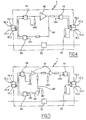
- FIG. 5 A third variant of the connecting device 1 according to the first embodiment is shown in Figure 5.
- the third variant is based on the second variant described above.
- the branch 60 has a connection point between the two amplifiers 18 and a connection point to isolation transformer 22 and includes an amplifier 61 analog.
- the use of two amplifiers 18 allows to increase the reliability of the connecting device. Indeed, the only way for a message to flow from the computer 2.2 to the computer 2.1 would a first failure occurs on the amplifier 18 neighbor of the 15.2 connector and leaves a short circuit the input and output of this amplifier. However, if the first failure occurred, the amplifier 18 near the connector 14.1 continues to work, it imposes its level exit and block any signal that goes back through the amplifier failed. It should therefore occur a second fault, on the amplifier 18 next to the connector 14.1, which leaves open the output of this amplifier.
- the first failure has a probability of occurrence extremely weak if not zero.
- the probability of simultaneous appearance of both breakdowns is even more low.
- the device for link 1 comprises, according to the second embodiment of the invention a transceiver 30 having terminals receiver 31 connected by a transformer 32 to input connector 14.1 and terminals external transmission 33 connected by a transformer isolation 34 to the output connector 15.1.
- the transceiver 30 also includes internal transmission terminals 35 connected via an xMII bus 36 to a buffer 38 and internal receiving terminals 37 not connected.
- the connecting device comprises a transceiver 40 having external receiving terminals 41 connected through an isolation transformer 42 to input connector 14.2 and transmission terminals external 43 connected via a transformer isolation 44 to the output connector 14.2.
- the Transceiver 40 also has transmission terminals internal 45 not connected and receiving terminals internal 47 connected via a bus xMII 46 to the buffer 38.
- the transceiver 30 transmits via its transmission terminals external 33 a carrier to the connector of output 15.1 and therefore to the external receiving terminals 10.1 of the transceiver 5.1.
- the buffer 37 makes it possible to adapt the flow rate internal transmission terminals 35 of the transceiver 30 to the internal reception terminals 47 of the transceiver 40 and also allows a repetition of the message.
- XMII buses 36 and 46 are unidirectional and can not be so be used to convey a message of the ETHERNET 3.2 interface to the ETHERNET 3.1 interface.
- the external transmission terminals 33 of the transceiver 30 are connected to the receiving terminals interface 10.1 of the ETHERNET interface transceiver 5.1 3.1 and send to them the signal of integrity of line.
- the 2.1 computer includes a port receiving 51 discrete signals and the computer 2.2 comprises a transmitting port 52 of discrete signals.
- the connecting device 1 comprises a filter low-pass 53 connected to the port of issue 52 of the computer 2.2 and to the receiver port 51 of the computer 2.1 for pass signals with a lower frequency or equal to a hertz. These signals can be used to test the unidirectional link and for example check that a message sent by the 2.1 computer has been been received by the computer 2.2.
- the low-pass filter 53 prevents the passage of advanced signals, which would necessarily a frequency higher than one hertz, so that it is not possible from the second computer to control or cause malfunctions on the first computer by this low frequency link.
- the diagram of the connecting device may be different from the one described.
- the device for link may lack analogue amplifier between connectors 14.1, 15.2 (the irreversible nature of the unidirectional link is then ensured less reliable).
- the first and second variants it is possible to use two amplifiers 18 instead of one and in the third variant, it is possible to use a single amplifier 18 instead of two. More than two amplifiers 18 can be used.
- switches can be arranged between the transformer 42 and the external receiving terminals 41 and between the transformer 34 and the transmission terminals external 33 to allow the choice be the establishment a direct connection between connectors 14.2 and 15.1 for message transmission from computer 2.2 to computer 2.1, the interruption of this connection (The transceiver 30 then constituting the signal source line integrity).
- ETHERNET interfaces are associated with computers
- ETHERNET interfaces can be associated with any network equipment including a router, a computer, a bridge, a switch or whatever.
- the invention has been described more particularly for an application to a 100 base link TX, the invention is also applicable to other types ETHERNET networks and in particular the 10 megabit networks, or with some modifications to the 1000 megabit networks or fiber optics.
Landscapes
- Engineering & Computer Science (AREA)
- Computer Networks & Wireless Communication (AREA)
- Signal Processing (AREA)
- Small-Scale Networks (AREA)
Abstract
Description
- la figure 1 est une vue schématique d'un réseau dans lequel est implanté un dispositif conforme à l'invention,
- la figure 2 est une vue schématique d'un tel dispositif, selon un premier mode de réalisation,
- la figure 3 est une vue schématique d'une première variante de réalisation du dispositif conforme au premier mode de réalisation,
- la figure 4 est une vue schématique d'une deuxième variante de réalisation du dispositif conforme au premier mode de réalisation de l'invention,
- la figure 5 est une vue schématique d'une troisième variante de réalisation du dispositif conforme au premier mode de réalisation,
- la figure 6 est une vue schématique d'un tel dispositif, selon un deuxième mode de réalisation.
- un état de blocage de la liaison dans lequel le commutateur 24 est dans son premier état et l'interrupteur 25 est ouvert de sorte que le connecteur d'entrée 14.2 est déconnecté du connecteur de sortie 15.1 et que, la source de signal d'intégrité de ligne 21 n'étant pas alimentée, le signal d'intégrité de ligne n'est pas transmis au connecteur de sortie 15.1 et le transceiver 5.1 ne peut fonctionner.
- un état de liaison unidirectionnelle dans lequel le commutateur 22 est dans sa première position et l'interrupteur 23 est fermé de sorte que le connecteur d'entrée 14.2 est déconnecté du connecteur de sortie 15.1 et que la source de signal d'intégrité de ligne 21 est alimentée et transmet le signal d'intégrité de ligne au connecteur de sortie 15.1. Seule la liaison de l'ordinateur 2.1 vers l'ordinateur 2.2 est alors possible.
- un état de liaison bidirectionnelle dans lequel le commutateur 22 est dans son deuxième état de sorte que le connecteur d'entrée 14.2 est connecté au connecteur de sortie 15.1 permettant ainsi la transmission de messages de l'ordinateur 2.1 vers l'ordinateur 2.2 et la transmission de messages de l'ordinateur 2.2 vers l'ordinateur 2.1.
Claims (8)
- Dispositif de liaison unidirectionnelle entre au moins une première interface ETHERNET et une deuxième interface ETHERNET (3.1, 3.2) qui comprennent respectivement un premier transmetteur-émetteur (5.1) et un deuxième transmetteur-émetteur (5.2) pourvus chacun de bornes de transmission externe de message (9.1, 9.2) et de bornes de réception externe de message (10.1, 10.2), caractérisé en ce que le dispositif comprend un organe de liaison (18 ; 30, 36, 37, 46, 40) des bornes de transmission externe du premier transmetteur-émetteur aux bornes de réception externe du deuxième transmetteur-émetteur et un organe d'émission (21 ; 30) d'un signal d'intégrité de ligne connecté aux bornes de réception externe du premier transmetteur-émetteur, les bornes de transmission externe du deuxième transmetteur-émetteur étant maintenues déconnectées des bornes de réception externe du premier transmetteur-émetteur.
- Dispositif de liaison selon la revendication 1, caractérisé en ce que l'organe de liaison comprend au moins un amplificateur analogique (18) raccordé au premier transmetteur-émetteur (5.1) et au deuxième transmetteur-émetteur (5.2) pour amplifier le message provenant du premier transmetteur-émetteur en direction du deuxième transmetteur-émetteur.
- Dispositif de liaison selon la revendication 2, caractérisé en ce que l'organe d'émission comprend une dérivation (60) raccordant une sortie de l'amplificateur analogique (18) aux bornes de réception externe (9.1) du premier transmetteur-émetteur (5.1).
- Dispositif de liaison selon la revendication 3, caractérisé en ce que la dérivation (60) comprend au moins un amplificateur analogique (61).
- Dispositif de liaison selon la revendication 2, caractérisé en ce que l'organe d'émission du signal d'intégrité de ligne comprend un transmetteur-émetteur (21) ayant des bornes de transmission externe reliées aux bornes de réception externe (10.1) du premier transmetteur-émetteur (5.1).
- Dispositif de liaison selon la revendication 1, caractérisé en ce qu'il comprend un troisième transmetteur-émetteur (30) ayant des bornes de transmission externe (33) et des bornes de réception externe (31) respectivement reliées aux bornes de réception externe (10.1) et aux bornes de transmission externe (9.1) du premier transmetteur-émetteur (5.1), un quatrième transmetteur-émetteur (40) ayant des bornes de transmission externe (43) et des bornes de réception externe (41) respectivement reliées aux bornes de réception externe (10.2) et aux bornes de transmission externe (9.2) du deuxième transmetteur-émetteur (5.2), le troisième transmetteur-émetteur ayant des bornes de transmission interne (35) reliées à des bornes de réception interne (47) du quatrième transmetteur-émetteur par l'intermédiaire d'une mémoire tampon (38) et des bornes de réception interne (37) maintenues déconnectées des bornes de transmission interne (45) du quatrième transmetteur-émetteur.
- Dispositif de liaison selon la revendication 1, caractérisé en ce que la première interface étant associée à un premier ordinateur (2.1) comprenant un port d'entrée (51) de signaux discrets et la deuxième interface étant associée à un deuxième ordinateur (2.2) comprenant un port de sortie (52) de signaux discrets, le dispositif comprend un organe de liaison raccordé à ces ports et pourvu d'un filtre passe-bas (53).
- Dispositif de liaison selon la revendication 7, caractérisé en ce que le filtre passe-bas (53) est agencé pour laisser passer les signaux de fréquence inférieure à un hertz environ.
Applications Claiming Priority (4)
| Application Number | Priority Date | Filing Date | Title |
|---|---|---|---|
| FR0313462 | 2003-11-18 | ||
| FR0313462A FR2862398A1 (fr) | 2003-11-18 | 2003-11-18 | Dispositif de liaison unidirectionnelle dans un reseau ethernet |
| FR0407347 | 2004-07-02 | ||
| FR0407347A FR2862399B3 (fr) | 2003-11-18 | 2004-07-02 | Dispositif de liaison unidirectionnelle dans un reseau ethernet |
Publications (2)
| Publication Number | Publication Date |
|---|---|
| EP1533947A1 true EP1533947A1 (fr) | 2005-05-25 |
| EP1533947B1 EP1533947B1 (fr) | 2013-06-26 |
Family
ID=34436809
Family Applications (1)
| Application Number | Title | Priority Date | Filing Date |
|---|---|---|---|
| EP04292614.7A Expired - Lifetime EP1533947B1 (fr) | 2003-11-18 | 2004-11-04 | Dispositif de liaison unidirectionnelle dans un reseau ethernet |
Country Status (4)
| Country | Link |
|---|---|
| US (1) | US7515603B2 (fr) |
| EP (1) | EP1533947B1 (fr) |
| CA (1) | CA2487583C (fr) |
| FR (1) | FR2862399B3 (fr) |
Cited By (1)
| Publication number | Priority date | Publication date | Assignee | Title |
|---|---|---|---|---|
| EP1962215A1 (fr) * | 2007-02-26 | 2008-08-27 | Sagem Defense Securite | Dispositif de connexion sélective permettant la connexion d'au moins un périphérique à un ordinateur cible et système de controle sélectif comportant un tel dispositif |
Families Citing this family (3)
| Publication number | Priority date | Publication date | Assignee | Title |
|---|---|---|---|---|
| US7921416B2 (en) | 2006-10-20 | 2011-04-05 | Yahoo! Inc. | Formal language and translator for parallel processing of data |
| US8774187B2 (en) * | 2011-10-24 | 2014-07-08 | Richard L. Hartman | Methods, systems, and devices for interfacing to networks |
| FR3015830B1 (fr) | 2013-12-19 | 2017-03-17 | Sagem Defense Securite | Dispositif d'interconnexion de reseaux de communication a securite controlee |
Citations (4)
| Publication number | Priority date | Publication date | Assignee | Title |
|---|---|---|---|---|
| US5311114A (en) * | 1992-10-27 | 1994-05-10 | Seeq Technology, Incorporated | Apparatus and method for full-duplex ethernet communications |
| US5608729A (en) * | 1995-04-20 | 1997-03-04 | Lucent Technologies Inc. | Method and apparatus for providing two-way data communication cover a widely distributed network |
| EP1164766A2 (fr) * | 2000-06-16 | 2001-12-19 | Ionos Co., Ltd. | Dispositif de contrôle de connections de commutation |
| US20030182580A1 (en) * | 2001-05-04 | 2003-09-25 | Lee Jai-Hyoung | Network traffic flow control system |
Family Cites Families (3)
| Publication number | Priority date | Publication date | Assignee | Title |
|---|---|---|---|---|
| US4782300A (en) * | 1986-03-03 | 1988-11-01 | International Business Machines Corporation | Differential transceiver with line integrity detection |
| JP3160350B2 (ja) * | 1991-05-30 | 2001-04-25 | 株式会社リコー | 通信網制御方法 |
| US5742602A (en) * | 1995-07-12 | 1998-04-21 | Compaq Computer Corporation | Adaptive repeater system |
-
2004
- 2004-07-02 FR FR0407347A patent/FR2862399B3/fr not_active Expired - Lifetime
- 2004-11-04 EP EP04292614.7A patent/EP1533947B1/fr not_active Expired - Lifetime
- 2004-11-15 CA CA2487583A patent/CA2487583C/fr not_active Expired - Fee Related
- 2004-11-17 US US10/989,493 patent/US7515603B2/en active Active
Patent Citations (4)
| Publication number | Priority date | Publication date | Assignee | Title |
|---|---|---|---|---|
| US5311114A (en) * | 1992-10-27 | 1994-05-10 | Seeq Technology, Incorporated | Apparatus and method for full-duplex ethernet communications |
| US5608729A (en) * | 1995-04-20 | 1997-03-04 | Lucent Technologies Inc. | Method and apparatus for providing two-way data communication cover a widely distributed network |
| EP1164766A2 (fr) * | 2000-06-16 | 2001-12-19 | Ionos Co., Ltd. | Dispositif de contrôle de connections de commutation |
| US20030182580A1 (en) * | 2001-05-04 | 2003-09-25 | Lee Jai-Hyoung | Network traffic flow control system |
Cited By (3)
| Publication number | Priority date | Publication date | Assignee | Title |
|---|---|---|---|---|
| EP1962215A1 (fr) * | 2007-02-26 | 2008-08-27 | Sagem Defense Securite | Dispositif de connexion sélective permettant la connexion d'au moins un périphérique à un ordinateur cible et système de controle sélectif comportant un tel dispositif |
| FR2913155A1 (fr) * | 2007-02-26 | 2008-08-29 | Sagem Defense Securite | Dispositif de connexion selective permettant la connexion d'au moins un peripherique a un ordinateur cible et systeme de controle selectif comportant un tel dispositif |
| US8194697B2 (en) | 2007-02-26 | 2012-06-05 | Sagem Defense Securite | Selective connection device allowing connection of at least one peripheral to a target computer and a selective control system comprising such a device |
Also Published As
| Publication number | Publication date |
|---|---|
| CA2487583A1 (fr) | 2005-05-18 |
| FR2862399A1 (fr) | 2005-05-20 |
| US7515603B2 (en) | 2009-04-07 |
| US20050105548A1 (en) | 2005-05-19 |
| EP1533947B1 (fr) | 2013-06-26 |
| FR2862399B3 (fr) | 2006-01-06 |
| CA2487583C (fr) | 2011-05-03 |
Similar Documents
| Publication | Publication Date | Title |
|---|---|---|
| FR2502871A1 (fr) | Systeme de commutation et de combinaison de signaux pour un systeme de communication radio | |
| EP1962215B1 (fr) | Dispositif de connexion sélective permettant la connexion d'au moins un périphérique à un ordinateur cible et système de controle sélectif comportant un tel dispositif | |
| EP0860778A1 (fr) | Dispositif et procédé de détection d'erreurs sur un circuit intégré comportant un port parallèle série | |
| EP1349078B1 (fr) | Installation, passerelle et procédé de téléchargement d'informations entre des équipements embarqués sur un aéronef et des moyens de chargement non-embarqués | |
| EP0724218A1 (fr) | Architecture de calculateur tolérante aux fautes | |
| CA2487583C (fr) | Dispositif de liaison unidirectionnelle utilisable dans un reseau ethernet | |
| EP0962869B1 (fr) | Circuit d'interface bistandard pour liaison série | |
| EP2878086B1 (fr) | Système de multi-transmission unidirectionnelle | |
| WO2010070209A1 (fr) | Méthode et dispositif de contrôle d'un réglage d'un état de commutation d' un système de commutation électrique lié au domaine des véhicules guidés | |
| EP1570605A1 (fr) | Reseau ethernet en double anneau | |
| EP1686758B1 (fr) | Système sécurisé d'interconnexion monodirectionnelle | |
| EP0002971A1 (fr) | Dispositif de couplage à une ligne de transmission optique et système de transmission comportant de tels dispositifs | |
| FR2862398A1 (fr) | Dispositif de liaison unidirectionnelle dans un reseau ethernet | |
| FR2696890A1 (fr) | Système de transmission de données dans un satellite. | |
| EP2781066B1 (fr) | Dispositif de raccordement selectif d'un premier equipement a une pluralite de deuxiemes equipements et ensemble de traitement de donnees comprenant un tel dispositif | |
| EP0115994A1 (fr) | Interface pour relier un système informatique à un dispositif actionneur | |
| EP3675441A1 (fr) | Commutateur pour un système de communication avionique et système de communication avionique comportant un tel commutateur | |
| EP0275779B1 (fr) | Dispositif à relais directionnels de plusieurs types | |
| EP0694238A1 (fr) | Procede d'augmentation de la vitesse de transmission | |
| CA2324430A1 (fr) | Dispositif et boitier pour raccordement a un reseau local | |
| FR2759798A1 (fr) | Procede d'initialisation d'une liaison serie entre deux circuits integres comportant un port parallele serie et dispositif de mise en oeuvre du procede | |
| EP3454512A1 (fr) | Réseau de communication, système de mesure, moyen de transport et procédé de construction d'un réseau de communication associés | |
| FR3103340A1 (fr) | Système avionique d’un aéronef. | |
| FR2695780A1 (fr) | Procédé de détection d'un court-circuit entre les lignes d'un bus transmettant des données numériques sous forme de signaux différentiels de tension. | |
| FR2776443A1 (fr) | Circuit d'isolation electrique entre un bus bidirectionnel et un circuit peripherique |
Legal Events
| Date | Code | Title | Description |
|---|---|---|---|
| PUAI | Public reference made under article 153(3) epc to a published international application that has entered the european phase |
Free format text: ORIGINAL CODE: 0009012 |
|
| AK | Designated contracting states |
Kind code of ref document: A1 Designated state(s): AT BE BG CH CY CZ DE DK EE ES FI FR GB GR HU IE IS IT LI LU MC NL PL PT RO SE SI SK TR |
|
| AX | Request for extension of the european patent |
Extension state: AL HR LT LV MK YU |
|
| 17P | Request for examination filed |
Effective date: 20051004 |
|
| RAP1 | Party data changed (applicant data changed or rights of an application transferred) |
Owner name: SAGEM DEFENSE SECURITE |
|
| AKX | Designation fees paid |
Designated state(s): DE ES FR GB IT |
|
| 17Q | First examination report despatched |
Effective date: 20090612 |
|
| GRAP | Despatch of communication of intention to grant a patent |
Free format text: ORIGINAL CODE: EPIDOSNIGR1 |
|
| RIN1 | Information on inventor provided before grant (corrected) |
Inventor name: SOREL, HERVE Inventor name: COURTEILLE, JEAN-MARIE |
|
| GRAS | Grant fee paid |
Free format text: ORIGINAL CODE: EPIDOSNIGR3 |
|
| GRAP | Despatch of communication of intention to grant a patent |
Free format text: ORIGINAL CODE: EPIDOSNIGR1 |
|
| GRAA | (expected) grant |
Free format text: ORIGINAL CODE: 0009210 |
|
| INTG | Intention to grant announced |
Effective date: 20130507 |
|
| AK | Designated contracting states |
Kind code of ref document: B1 Designated state(s): DE ES FR GB IT |
|
| REG | Reference to a national code |
Ref country code: GB Ref legal event code: FG4D Free format text: NOT ENGLISH |
|
| REG | Reference to a national code |
Ref country code: DE Ref legal event code: R096 Ref document number: 602004042527 Country of ref document: DE Effective date: 20130822 |
|
| PG25 | Lapsed in a contracting state [announced via postgrant information from national office to epo] |
Ref country code: ES Free format text: LAPSE BECAUSE OF FAILURE TO SUBMIT A TRANSLATION OF THE DESCRIPTION OR TO PAY THE FEE WITHIN THE PRESCRIBED TIME-LIMIT Effective date: 20131007 |
|
| PLBE | No opposition filed within time limit |
Free format text: ORIGINAL CODE: 0009261 |
|
| STAA | Information on the status of an ep patent application or granted ep patent |
Free format text: STATUS: NO OPPOSITION FILED WITHIN TIME LIMIT |
|
| PG25 | Lapsed in a contracting state [announced via postgrant information from national office to epo] |
Ref country code: IT Free format text: LAPSE BECAUSE OF FAILURE TO SUBMIT A TRANSLATION OF THE DESCRIPTION OR TO PAY THE FEE WITHIN THE PRESCRIBED TIME-LIMIT Effective date: 20130626 |
|
| 26N | No opposition filed |
Effective date: 20140327 |
|
| REG | Reference to a national code |
Ref country code: DE Ref legal event code: R097 Ref document number: 602004042527 Country of ref document: DE Effective date: 20140327 |
|
| REG | Reference to a national code |
Ref country code: FR Ref legal event code: PLFP Year of fee payment: 12 |
|
| REG | Reference to a national code |
Ref country code: FR Ref legal event code: PLFP Year of fee payment: 13 |
|
| REG | Reference to a national code |
Ref country code: FR Ref legal event code: CD Owner name: SAFRAN ELECTRONICS & DEFENSE, FR Effective date: 20170111 |
|
| REG | Reference to a national code |
Ref country code: FR Ref legal event code: PLFP Year of fee payment: 14 |
|
| REG | Reference to a national code |
Ref country code: FR Ref legal event code: PLFP Year of fee payment: 15 |
|
| PGFP | Annual fee paid to national office [announced via postgrant information from national office to epo] |
Ref country code: GB Payment date: 20231019 Year of fee payment: 20 |
|
| PGFP | Annual fee paid to national office [announced via postgrant information from national office to epo] |
Ref country code: FR Payment date: 20231019 Year of fee payment: 20 Ref country code: DE Payment date: 20231019 Year of fee payment: 20 |
|
| REG | Reference to a national code |
Ref country code: DE Ref legal event code: R071 Ref document number: 602004042527 Country of ref document: DE |
|
| REG | Reference to a national code |
Ref country code: GB Ref legal event code: PE20 Expiry date: 20241103 |
|
| PG25 | Lapsed in a contracting state [announced via postgrant information from national office to epo] |
Ref country code: GB Free format text: LAPSE BECAUSE OF EXPIRATION OF PROTECTION Effective date: 20241103 |
|
| PG25 | Lapsed in a contracting state [announced via postgrant information from national office to epo] |
Ref country code: GB Free format text: LAPSE BECAUSE OF EXPIRATION OF PROTECTION Effective date: 20241103 |