EP1533926A1 - Radio transmission device, radio reception device, and method for selecting transmission cancel subcarriers - Google Patents
Radio transmission device, radio reception device, and method for selecting transmission cancel subcarriers Download PDFInfo
- Publication number
- EP1533926A1 EP1533926A1 EP03795323A EP03795323A EP1533926A1 EP 1533926 A1 EP1533926 A1 EP 1533926A1 EP 03795323 A EP03795323 A EP 03795323A EP 03795323 A EP03795323 A EP 03795323A EP 1533926 A1 EP1533926 A1 EP 1533926A1
- Authority
- EP
- European Patent Office
- Prior art keywords
- section
- subcarriers
- transmission
- selection
- subcarrier
- Prior art date
- Legal status (The legal status is an assumption and is not a legal conclusion. Google has not performed a legal analysis and makes no representation as to the accuracy of the status listed.)
- Granted
Links
Images










Classifications
-
- H—ELECTRICITY
- H04—ELECTRIC COMMUNICATION TECHNIQUE
- H04L—TRANSMISSION OF DIGITAL INFORMATION, e.g. TELEGRAPHIC COMMUNICATION
- H04L27/00—Modulated-carrier systems
- H04L27/26—Systems using multi-frequency codes
- H04L27/2601—Multicarrier modulation systems
- H04L27/2614—Peak power aspects
- H04L27/2615—Reduction thereof using coding
-
- H—ELECTRICITY
- H04—ELECTRIC COMMUNICATION TECHNIQUE
- H04L—TRANSMISSION OF DIGITAL INFORMATION, e.g. TELEGRAPHIC COMMUNICATION
- H04L1/00—Arrangements for detecting or preventing errors in the information received
- H04L1/004—Arrangements for detecting or preventing errors in the information received by using forward error control
- H04L1/0041—Arrangements at the transmitter end
-
- H—ELECTRICITY
- H04—ELECTRIC COMMUNICATION TECHNIQUE
- H04L—TRANSMISSION OF DIGITAL INFORMATION, e.g. TELEGRAPHIC COMMUNICATION
- H04L1/00—Arrangements for detecting or preventing errors in the information received
- H04L1/004—Arrangements for detecting or preventing errors in the information received by using forward error control
- H04L1/0056—Systems characterized by the type of code used
- H04L1/0067—Rate matching
- H04L1/0068—Rate matching by puncturing
-
- H—ELECTRICITY
- H04—ELECTRIC COMMUNICATION TECHNIQUE
- H04L—TRANSMISSION OF DIGITAL INFORMATION, e.g. TELEGRAPHIC COMMUNICATION
- H04L1/00—Arrangements for detecting or preventing errors in the information received
- H04L1/12—Arrangements for detecting or preventing errors in the information received by using return channel
- H04L1/16—Arrangements for detecting or preventing errors in the information received by using return channel in which the return channel carries supervisory signals, e.g. repetition request signals
- H04L1/18—Automatic repetition systems, e.g. Van Duuren systems
- H04L1/1812—Hybrid protocols; Hybrid automatic repeat request [HARQ]
- H04L1/1819—Hybrid protocols; Hybrid automatic repeat request [HARQ] with retransmission of additional or different redundancy
-
- H—ELECTRICITY
- H04—ELECTRIC COMMUNICATION TECHNIQUE
- H04L—TRANSMISSION OF DIGITAL INFORMATION, e.g. TELEGRAPHIC COMMUNICATION
- H04L5/00—Arrangements affording multiple use of the transmission path
- H04L5/003—Arrangements for allocating sub-channels of the transmission path
- H04L5/0044—Allocation of payload; Allocation of data channels, e.g. PDSCH or PUSCH
- H04L5/0046—Determination of the number of bits transmitted on different sub-channels
-
- H—ELECTRICITY
- H04—ELECTRIC COMMUNICATION TECHNIQUE
- H04L—TRANSMISSION OF DIGITAL INFORMATION, e.g. TELEGRAPHIC COMMUNICATION
- H04L5/00—Arrangements affording multiple use of the transmission path
- H04L5/0001—Arrangements for dividing the transmission path
- H04L5/0003—Two-dimensional division
- H04L5/0005—Time-frequency
- H04L5/0007—Time-frequency the frequencies being orthogonal, e.g. OFDM(A) or DMT
Definitions
- the present invention relates to a radio transmission apparatus, radio reception apparatus and method of selecting transmission cancellation subcarriers, and more particularly, to a radio transmission apparatus, radio reception apparatus and method of selecting transmission cancellation subcarriers in a radio communication system carrying out error correction coding.
- a multicarrier (MC) modulation scheme such as an OFDM (Orthogonal Frequency Division Multiplexing) scheme is becoming a focus of attention.
- the multicarrier modulation scheme is a technology for realizing high-speed transmission as a result of transmitting data using a plurality of carriers (subcarriers) whose transmission rate is suppressed to an extent that frequency selective fading is not generated.
- the OFDM scheme is a scheme with the highest frequency utilization efficiency among multicarrier modulation schemes and it can be implemented in a relatively simple hardware configuration, and therefore the OFDM scheme is capturing special attention and is now under study from various angles.
- the present inventor has come to implement the present invention noticing that a parity bit is a bit with a lower degree of importance than a systematic bit and when one bit needs to be removed, removing a parity bit has a smaller influence on the deterioration of an error rate characteristic than removing a systematic bit.
- the present invention is characterized in that, of subcarriers to which a symbol made up of only systematic bits or only parity bits or a symbol made up of a mixture of both which are generated by coding transmission bits is mapped, subcarriers not to be transmitted (that is, subcarriers whose transmission is canceled) are selected from among subcarriers to which a symbol made up of only parity bits is mapped. Furthermore, when subcarriers whose transmission is canceled are selected from among subcarriers to which a symbol made up of only parity bits is mapped, the present invention is characterized by selecting a combination of subcarriers which results in the lowest peak power.
- the present invention is further characterized by not transmitting position information on subcarriers whose transmission is canceled separately.
- the present invention allows a radio communication system carrying out error correction coding to reduce peak power while suppressing deterioration of the error rate characteristic.
- the present invention can also prevent deterioration of transmission efficiency through transmission of position information.
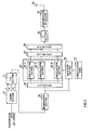
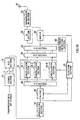
- FIG.1 is a block diagram showing a configuration of a radio transmission apparatus according to Embodiment 1 of the present invention.
- the radio transmission apparatus shown in FIG.1 includes a coding section 12, a parallel/serial conversion (P/S) section 14, a modulation section 16, a serial/parallel conversion (S/P) section 18, a selection section 20, a cancellation table 22, a cancellation section 24, an inverse fast Fourier transform (IFFT) section 26, a parallel/serial conversion (P/S) section 28, a guard interval (GI) section 30 and a transmission RF section 32, designed to transmit an OFDM symbol of a multicarrier signal in which some of a plurality of subcarriers making up the OFDM symbol are removed.
- the radio transmission apparatus shown in FIG.1 is mounted, for example, on a base station apparatus used for a mobile communication system.
- the coding section 12 carries out error correction coding on transmission data (a bit string) using systematic codes such as turbo codes.
- the coding section 12 encodes a transmission bit string using systematic codes and thereby generates systematic bits S which are transmission bits themselves and parity bits P which are redundant bits.
- the three bits of the systematic bit S and parity bits P 1 and P 2 are input in parallel to the P/S section 14.
- the P/S section 14 converts the bit strings input in parallel to serial bit strings and inputs S, P 1 and P 2 in that order to the modulation section 16.
- the modulation section 16 BPSK-modulates the systematic bit S and parity bits P 1 and P 2 to generate a symbol. If the input bit is "0", the modulation section 16 modulates it into a symbol of "1" and if the input bit is "1", the modulation section 16 modulates it into a symbol of "-1". Because of the BPSKmodulation, 1 symbol consists of 1 bit. The modulated symbols are input to the S/P section 18 and selection section 20.
- the S/P section 18 converts those symbols to parallel ones and inputs them to the cancellation section 24.
- K the number of subcarriers constituting 1 OFDM symbol
- the selection section 20 decides to which subcarriers the symbols consisting of only parity bits are mapped. Since the modulation section 16 in this embodiment carries out BPSK modulation and 1 symbol consists of 1 bit, the selection section 20 decides subcarriers to which parity bits are mapped. The position of mapping to each subcarrier within 1 OFDM symbol is known for each OFDM symbol beforehand, and therefore the selection section 20 can easily decide subcarriers to which parity bits are mapped.
- bit S is mapped to subcarrier f 1 , bit P 1 to f 2 , bit P 2 to f 3 , bit S to f 4; bit P 1 to f 5 , bit P 2 to f 6 , ..., bit S to f 13 , bit P 1 to f 14 and bit P 2 to f 15 .
- the mapping position varies from one OFDM symbol to another, but there is certain regularity, and therefore the selection section 20 can easily decide subcarriers to which parity bits are mapped in this case, too. Furthermore, even when coded bits are punctured or interleaved, puncture patterns or interleave patterns are known beforehand, and therefore the selection section 20 can easily decide subcarriers to which parity bits are mapped based on those patterns.
- the selection section 20 selects N subcarriers (L>N) as subcarriers to be excluded from transmission (whose transmission is to be canceled) and indicates the selected subcarriers to the cancellation section 24.
- the selection section 20 references the cancellation table 22 based on the value of a symbol input from the modulation section 16 and selects subcarriers whose transmission is to be canceled. The specific contents of the cancellation table 22 and specific method of selecting subcarrier whose transmission is to be canceled will be described later.
- subcarriers whose transmission is canceled are not subcarriers to which systematic bits are mapped but subcarriers to which parity bits are mapped is as follows. That is, when error correction coding is performed using systematic codes, parity bits can be said to have a lower degree of importance than systematic bits. That is, at a radio reception apparatus which receives OFDM symbols, its error rate characteristic deteriorates considerably when systematic bits are lost, but a desired error rate characteristic can be maintained even if some parity bits are lost. This is attributable to the fact that systematic bits constitute transmission bits themselves, while parity bits are redundant bits.
- the cancellation section 24 consists of cancellation sections 24-1 to 24-K.
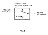
- the cancellation sections 24-1 to 24-K each have a configuration shown in FIG. 2 and the cancellation section corresponding to a subcarrier indicated by the selection section 20 connects a switch to the B side. For example, when the selection section 20 selects the subcarrier f 2 as one whose transmission is to be canceled, the cancellation section 24-2 changes the switch from the A side to the B side.
- a signal with an amplitude value "0" is input to the IFFT section 26 for the subcarrier f 2 , and therefore the IFFT section 26 obtains a sample value without including subcarrier f 2 . That is, transmission of the subcarrier f 2 is canceled.
- the IFFT section 26 applies an inverse fast Fourier transform to symbols or signals with amplitude values "0" input from the cancellation sections 24-1 to 24-K to transform them from a frequency area to a time area and then inputs sample values in the time area to the P/S section 28.
- signals with amplitude values "0" are input from the cancellation sections corresponding to subcarriers selected by the selection section 20 and signals with symbol values "-1" or "1" are input from the other cancellation sections, and therefore the IFFT section 26 performs IFFT using K-N subcarriers other than the subcarriers selected by the selection section 20.
- the sample values obtained at the IFFT section 26 are input in parallel to the P/S section 28.
- the P/S section 28 transforms the parallel sample values after the IFFT processing into serial values. In this way, an OFDM symbol which does not include subcarriers selected by the selection section 20 is generated.
- the OFDM symbol is subjected to predetermined radio processing such as up-conversion at the transmission RF section 32 and transmitted by radio from the antenna 34.
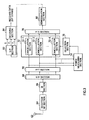
- FIG.3 is a block diagram showing a configuration of the radio reception apparatus according to Embodiment 1 of the present invention.
- the radio reception apparatus shown in FIG.3 includes an antenna 62, a reception RF section 64, a GI section 66, an S/P section 68, a fast Fourier transform (FFT) section 70, a cancellation section 72, a power measuring section 74, a selection section 76, a P/S section 78, a demodulation section 80, an S/P section 82 and a decoding section 84.
- the radio reception apparatus shown in FIG.3 is mounted, for example, on a mobile station apparatus used for a mobile communication system.
- an OFDM symbol transmitted from the radio transmission apparatus shown in FIG.1 is received by the antenna 62, subjected to predetermined radio processing such as down-conversion at the reception RF section 64, stripped of the guard interval at the GI section 66 and input to the S/P section 68.
- predetermined radio processing such as down-conversion at the reception RF section 64, stripped of the guard interval at the GI section 66 and input to the S/P section 68.
- the S/P section 68 serial/parallel-converts signals input in series from the GI section 66 into as many parallel signals as subcarriers and inputs the signals to the FFT section 70.
- the FFT section 70 applies a fast Fourier transform (FFT) to the output signals from the S/P section 68 and transforms them from a time area to a frequency area (that is, converts the signals to symbols for the respective subcarriers) and then inputs the symbols to the cancellation section 72 and power measuring section 74.
- FFT fast Fourier transform
- the power measuring section 74 measures reception power for each subcarrier (reception power of the respective subcarriers f 1 to f K ) and inputs the measuring result to the selection section 76.
- the selection section 76 selects subcarriers to be excluded from demodulation based on the measuring result from the power measuring section 74 and indicates the selected subcarriers to the cancellation sections 72. More specifically, of the subcarriers f 1 to f K , the selection section 76 selects N subcarriers having relatively small reception power. This number N is the number N of the subcarriers selected by the radio transmission apparatus as ones whose transmission is canceled and is a preset value. That is, the radio transmission apparatus presets the number N of subcarriers whose transmission is to be canceled and the selection section 76 selects N subcarriers from the lowest reception power as ones to be excluded from demodulation.
- the cancellation section 72 consists of cancellation sections 72-1 to 72-K.
- the cancellation sections 72-1 to 72-K each have a configuration shown in FIG. 4 and the cancellation section corresponding to a subcarrier indicated by the selection section 76 connects a switch to the B side. For example, when the selection section 76 selects the subcarrier f 2 as one to be excluded from demodulation, the cancellation section 72-2 changes the switch from the A side to the B side.
- a signal with an amplitude value "0" is input to the demodulation section 80 through the P/S section 78 for the subcarrier f 2 . In this way, demodulation of the subcarrier f 2 is canceled at the demodulation section 80.
- the P/S section 78 converts symbols or signals with amplitude values "0" input in parallel from the cancellation sections 72-1 to 72-K to signals in series and inputs them to the demodulation section 80.
- the demodulation section 80 BPSK-demodulates the input symbols and inputs them to the S/P section 82. If the input symbol is "1", the demodulation section 80 demodulates it into a bit "0" and if the input symbol is "-1", the demodulation section 80 demodulates it into a bit "1". Furthermore, for a signal with an amplitude value "0", the demodulation section 80 considers it as a bit "0" and inputs it to the S/P section 82. This makes it possible to obtain systematic bit S and parity bits P 1 and P 2 . The parity bits whose transmission is canceled by the radio transmission apparatus become bits "0".
- the S/P section 82 converts bits S, P 1 and P 2 input in that order to parallel bits and inputs those bits to the decoding section 84.
- the decoding section 84 carries out error correction decoding such as turbo decoding using the input bits. In this way, received data (bit string) is obtained.
- the radio transmission apparatus uses the subcarriers f 2 , f 3 , f 5 , f 6 , f 8 , f 9 , f 11 , f 12 , f 14 and f 15 to which parity bits are mapped as candidates for transmissioncancellation.
- error correction coding becomes meaningless, and therefore only transmission of some of the plurality of parity bits is canceled.
- N 5 subcarriers is canceled. This number N is a preset value.
- the radio transmission apparatus references the cancellation table shown in FIG.6 based on the values of bits mapped to the subcarriers f 1 to f 15 and decides subcarriers whose transmission is to be canceled.
- the bit value is pattern 5
- the bit value is pattern 5
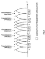
- the subcarriers after transmission cancellation are as shown in FIG.7.
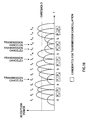
- the reception power of the respective subcarriers of the OFDM symbol received by the radio reception apparatus is as shown in FIG.8. Since transmission of the subcarriers f 2 , f 6 , f 8 , f 12 and f 14 is canceled at the radio transmission apparatus, their reception power becomes smaller than that of the other subcarriers.
- the radio reception apparatus sets their amplitude values to "0". As a result, the subcarriers appear as shown in FIG.9.
- the radio reception apparatus obtains P 1 , P 2 , P 1 , P 2 and P 1 as bits "0" which are originally supposed to be mapped to the subcarriers f 2 , f 6 , f 8 , f 12 and f 14 and transmitted.
- this embodiment selects subcarriers whose transmission is to be canceled from among subcarriers to which a symbol consisting of only parity bits is mapped. Furthermore, a combination of subcarriers whose peak power becomes a minimum is decided as the combination of subcarriers whose transmission is to be canceled. Therefore, according to this embodiment, it is possible to reduce peak power while suppressing deterioration of the error rate characteristic. Furthermore, position information of subcarriers whose transmission is canceled is not transmitted separately, and it is therefore possible to prevent a reduction of the transmission efficiency caused by transmission of the position information.
- the radio transmission apparatus performs transmission cancellation only when peak power of an OFDM symbol reaches or exceeds a threshold.
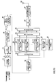
- FIG.10 is a block diagram showing a configuration of a radio transmission apparatus according to Embodiment 2 of the present invention.
- the same components as those in Embodiment 1 (FIG.1) are assigned the same reference numerals and explanations thereof will be omitted.
- a buffer 36 stores symbols input from a modulation section 16 in OFDM symbol units.
- the buffer 36 stores the symbols in sets of 15 subcarriers.
- a peak power detection section 40 detects peak power of an OFDM symbol input from a P/S section 28. The detected peak power value is input to a selection section 20.
- a buffer 38 stores OFDM symbols input from the P/S section 28.
- the selection section 20 stores 10 C 5 selection patterns of sub carriers whose transmission is to be canceled.
- the selection section 20 instructs the buffer 38 to output this OFDM symbol. Therefore, when the peak power of the OFDM symbol is lower than the threshold, the OFDM symbol containing no subcarriers whose transmission is canceled is transmitted to the radio reception apparatus.
- the selection section 20 instructs the buffer 36 to output a symbol string.
- the buffer 36 inputs the same symbol string to the S/P section 18 10 C 5 times per 1 OFDM symbol.
- the selection section 20 every time the selection section 20 carries out selection processing, OFDM symbols whose transmission is canceled in different selection patterns are stored in the buffer 38 and the peak power is detected by the peak power detection section 40. Therefore, the buffer 38 stores 10 C 5 OFDM symbols and the peak power detection section 40 detects peak power of 10 C 5 OFDM symbols. Then, the selection section 20 selects an OFDM symbol whose peak power is a minimum out of the 10 C 5 OFDM symbols and instructs the buffer 38 to output the selected OFDM symbol. In this way, the OFDM symbol whose peak power is lower than the threshold and whose peak power is a minimum is transmitted to the radio reception apparatus.
- this embodiment cancels transmission only when peak power of an OFDM symbol reaches or exceeds a threshold, and can thereby omit unnecessary transmission cancellation and consequently further suppress deterioration of the error rate characteristic when peak power is reduced.
- a radio transmission apparatus keeps the total transmit power of subcarriers to be transmitted constant.
- FIG.12 is a block diagram showing a configuration of a radio transmission apparatus according to Embodiment 3 of the present invention. Note that in FIG.12, the same components as those in Embodiment 1 (FIG.1) are assigned the same reference numerals and explanations thereof will be omitted.
- a selection section 20 indicates N subcarriers selected as ones whose transmission is to be canceled to a cancellation section 24 and a power control section 42.
- the power control section 42 consists of power control sections 42-1 to 42-K. K equals the number of a plurality of subcarriers included in 1 OFDM symbol and the power control sections 42-1 to 42-K correspond to subcarriers f 1 to f K respectively.
- the power control section 42 assigns transmit power corresponding to subcarriers whose transmission is canceled to subcarriers whose transmission is not canceled. That is, the transmit power which decreases because transmission of subcarriers selected by the selection section 20 is canceled is assigned to subcarriers other than subcarriers whose transmission is to be canceled. This assignment is performed more specifically as follows.
- K-N subcarriers that is, subcarriers which are transmitted
- K/(K-N) K/(K-N)
- this embodiment assigns transmit power corresponding to the transmit power decrease because of cancellation of transmission of the subcarriers to subcarriers other than the subcarriers whose transmission is to be canceled, and can thereby reduce peak power while keeping transmit power of OFDM symbols constant.
- This embodiment will describe a case where a modulation section 16 modulates two or more bits into 1 symbol.
- FIG.13 is a block diagram showing a configuration of a radio transmission apparatus according to Embodiment 4 of the present invention. Note that the same components in FIG.13 as those in Embodiment 1 (FIG.1) are assigned the same reference numerals and explanations thereof will be omitted.
- the modulation section 16 performs QPSK modulation on bits input from an input order control section 46. That is, the modulation section 16 generates 1 symbol for every 2 bits which are input successively.
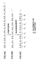
- a P/S section 14 outputs bits S, P 1 , P 2 in that order as shown in FIG.14A.
- the puncture section 44 punctures parity bits.
- the puncture section 44 punctures P 1 and P 2 alternately.
- the bit string output from the puncture section 44 is as shown in FIG.14B. This bit string is input to the input order control section 46.
- the modulation section 16 generates 1 symbol for every 2 bits input successively (performs QPSK modulation), and therefore if the bit string in FIG.14B is input to the modulation section 16 in its original order, no symbol consisting of only parity bits is generated, which makes it impossible to select subcarriers whose transmission is to be canceled.
- the input order control section 46 rearranges the bit string shown in FIG.14B as the bit string shown in FIG.14C. That is, the input order control section 46 controls the order in which the systematic bits and parity bits input from the puncture section 44 are input to the modulation section 16. More specifically, the input order control section 46 performs control in such a way that two parity bits are input successively to the modulation section 16. In this way, in the modulation section 16, symbols consisting of only parity bits are generated.
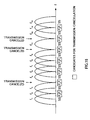
- the selection section 20 selects subcarriers to which symbols consisting of P 2 and P 1 , that is, symbols consisting of only parity bits are mapped as candidates for transmission cancellation (FIG.15). Then, the selection section 20 cancels transmission of only some of these candidates.
- This embodiment has explained QPSK modulation as an example, but this embodiment is also applicable to modulation schemes whereby three or more bits are modulated into one symbol (8PSK, 16QAM, 64QAM, etc.).
- the input order control section 46 performs control in such a way that four parity bits are input successively to the modulation section 16.
- this embodiment can definitely generate subcarriers carrying only parity bits and select subcarriers whose transmission is to be canceled.
- a radio transmission apparatus selects subcarriers whose reception power at a radio reception apparatus falls to or below a threshold out of subcarriers to which symbols consisting of only parity bits are mapped as subcarriers whose transmission is to be canceled.
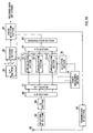
- FIG.16 is a block diagram showing a configuration of a radio transmission apparatus according to Embodiment 5 of the present invention. Note that the same components in FIG.16 as those in Embodiment 1 (FIG.1) are assigned the same reference numerals and explanations thereof will be omitted. Furthermore, FIG.17 is a block diagram showing a configuration of a radio reception apparatus according to Embodiment 5 of the present invention. Note that the same components in FIG.17 as those in Embodiment 1 (FIG.3) are assigned the same reference numerals and explanations thereof will be omitted.
- pilot signals are modulated by a modulation section 16, passed through an S/P section 18 and a cancellation section 24, and mapped to subcarriers f 1 to f 15 which constitute 1 OFDM symbol. Then, an OFDM symbol consisting of pilot signals is transmitted to the radio reception apparatus shown in FIG.17.
- a power measuring section 74 measures reception power of the subcarriers f 1 to f 15 of the OFDM symbol consisting of pilot signals. Then, the power measuring section 74 inputs notification information for notifying the radio transmission apparatus of a reception power value of each subcarrier to a modulation section 86. This notification information is modulated by the modulation section 86, up-converted by a transmission RF section 88 and transmitted from the antenna 62 to the radio transmission apparatus.
- notification information received through an antenna 34 is down-converted by a reception RF section 48 and demodulated by a demodulation section 50.
- the demodulated notification information is input to a selection section 20.
- the selection section 20 compares reception power values of the subcarriers f 1 to f 15 with a threshold and selects subcarriers whose reception power values are equal to or lower than the threshold out of subcarriers to which symbols consisting of only parity bits are mapped as subcarriers whose transmission is to be canceled.
- the selection section 20 selects these four subcarriers as subcarriers whose transmission is to be canceled.
- this embodiment does not transmit subcarriers whose reception power at the radio reception apparatus falls to or below a threshold out of subcarriers to which symbols consisting of only parity bits are mapped, and can thereby prevent unnecessary transmission of parity bits which are expected not to be received correctly at the radio reception apparatus.
- ARQ is a technology for improving an error rate by combining received signal (symbol) for every time retransmission is performed.
- the H-ARQ requires a radio reception apparatus to combine received signals.
- symbols mapped to those subcarriers are not transmitted and if transmission of the same subcarriers as those at the time of initial transmission is also canceled at the time of retransmission, the symbols mapped to the subcarriers are not transmitted at the time of retransmission either. This means that there exist symbols that cannot be combined at the radio reception apparatus and the error rate will not improve at all no matter how many times retransmission may be performed.
- the radio transmission apparatus selects different subcarriers between the time of initial transmission and the time of retransmission from among the subcarriers to which symbols consisting of only parity bits are mapped as the subcarriers whose transmission is to be canceled in a communication system which carries out H-ARQ (Hybrid Automatic Repeat reQuest).
- H-ARQ Hybrid Automatic Repeat reQuest
- FIG.19 is a block diagram showing a configuration of a radio reception apparatus according to Embodiment 6 of the present invention.
- the same components as those in Embodiment 1 (FIG.3) are assigned the same reference numerals and explanations thereof will be omitted.
- FIG.20 is a block diagram showing a configuration of a radio transmission apparatus according to Embodiment 6 of the present invention.
- the same components as those in Embodiment 1 (FIG.1) are assigned the same reference numerals and explanations thereof will be omitted.
- a decoding result (bit string) obtained by a decoding section 84 is input to an error detection section 90.
- the error detection section 90 carries out error detection such as CRC (Cyclic Redundancy Check) on the input decoding result. Then, the error detection section 90 generates an ACK (ACKnowledgment: positive response) or NACK (Negative ACKnowledgment: negative response) based on the error detection result and inputs it to a transmission RF section 92.
- the error detection section 90 generates an ACK when the decoding result is OK with no error or generates a NACK when the decoding result is NG with some error as a response signal to the error detection and inputs it to a transmission section 92.
- the transmission section 92 transmits ACK/NACK to the radio transmission apparatus shown in FIG.20 through an antenna 62.
- a signal including the ACK or NACK transmitted from the radio reception apparatus shown in FIG.19 is received by an antenna 34, subjected to predetermined radio processing such as down-conversion at the reception RF section 52 and input to an ACK/NACK detection section 54.
- the ACK/NACK detection section 54 detects the ACK or NACK from the input signal and inputs it to a retransmission control section 56. Symbols generated by a modulation section 16 are input to the retransmission control section 56.
- the retransmission control section 56 stores symbols input from the modulation section 16 and at the same time inputs the symbols to an S/P section 18 and a selection section 20.
- the retransmission control section 56 retransmits a symbol corresponding to the NACK.
- the retransmitted symbol is also input to the S/P section 18 and selection section 20.
- the selection section 20 performs the same operation as that in Embodiment 1 and stores the selection result in a selection result storage section 58. Then, at the time of first retransmission, the selection section 20 references the selection result at the time of initial transmission stored in the selection result storage section 58 and selects subcarriers different from the subcarriers at the time of initial transmission as subcarriers to be excluded from transmission. This selection result is also stored in the selection result storage section 58.
- the selection section 20 references the selection result at the time of initial transmission and the selection result at the time of first retransmission stored in the selection result storage section 58 and selects subcarriers different from the subcarriers at the time of initial transmission and at the time of first retransmission as subcarriers to be excluded from transmission. That is, the subcarriers selected by the selection section 20 at the time of retransmission as subcarriers whose transmission is to be canceled are selected from among subcarriers other than the already selected subcarriers.
- subcarriers selected at the time of retransmission as subcarriers whose transmission is to be canceled are selected only from among the subcarriers already transmitted before the time of retransmission. This will be explained more specifically using FIG.21 to FIG.23 below.
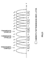
- FIG.21 shows a case at the initial transmission
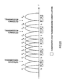
- FIG.22 shows a case at the first retransmission
- FIG.23 shows a case at the second retransmission.
- the three subcarriers whose transmission is to be canceled are selected as follows.
- the selection section 20 selects different subcarriers whose transmission is to be canceled between the time of the initial transmission and the time of retransmission, and, at the time of retransmission, selects the subcarriers whose transmission is to be canceled only from among the subcarriers already transmitted at the time of the initial transmission.
- subcarriers whose transmission is to be canceled are selected from among the subcarriers whose transmission is not canceled yet.
- this embodiment selects different subcarriers as subcarriers whose transmission is to be canceled between the time of the initial transmission and the time of retransmission, and, at the time of retransmission, selects the subcarriers whose transmission is to be canceled only from among the subcarriers already transmitted at the time of the initial transmission, and thereby preventing occurrence of subcarriers that are not transmitted even upon retransmission and reliably improving the error rate characteristics upon every retransmission.
- the present invention allows a radio communication system which carries out error correction coding to suppress deterioration of its error rate characteristic and at the same time reduce peak power.
- the present invention is preferably applicable to a radio communication terminal apparatus and radio communication base station apparatus, etc., used for a mobile communication system.
Landscapes
- Engineering & Computer Science (AREA)
- Signal Processing (AREA)
- Computer Networks & Wireless Communication (AREA)
- Detection And Prevention Of Errors In Transmission (AREA)
- Mobile Radio Communication Systems (AREA)
Abstract
Description
Claims (12)
- A radio transmission apparatus comprising:a coding section that encodes a transmission bit to generate a systematic bit and a parity bit;a modulation section that modulates the systematic bit and the parity bit generated by said coding section to generate a symbol;a selection section that carries out selection processing of selecting a subcarrier to which a symbol consisting of only parity bit is mapped out of the symbols generated by said modulation section as a subcarrier to be excluded from transmission;a genarating section that generates a multicarrier signal using subcarriers other than the subcarrier selected by said selection section out of subcarriers to which the symbols generated by said modulation section are mapped; anda transmission section that transmits the multicarrier signal generated by said generating section.
- The radio transmission apparatus according to claim 1, further comprising a table showing the correspondence between a plurality of patterns of values that are possibly taken by the symbols generated by said modulation section and a plurality of selection patterns of subcarriers selected by said selection section as subcarriers to be excluded from transmission, wherein said selection section references said table based on the values of the symbols generated by said modulation section and selects a selection pattern with the minimum peak power out of said plurality of selection patterns.
- The radio transmission apparatus according to claim 1, further comprising a detection section that detects peak power of the multicarrier signal generated by said generating section, wherein said selection section selects a selection pattern with the minimum peak power out of a plurality of selection patterns of the subcarriers to be excluded from transmission.
- The radio transmission apparatus according to claim 1, further comprising a detection section that detects peak power of the multicarrier signal generated by said generating section, wherein said selection section carries out said selection processing only when the peak power reaches or exceeds a threshold.
- The radio transmission apparatus according to claim 1, further comprising a detection section that detects peak power of the multicarrier signal generated by said generating section, wherein said transmission section transmits a multicarrier signal whose peak power is lower than a threshold out of the multicarrier signals generated by said generating section.
- The radio transmission apparatus according to claim 1, further comprising a power control section that assigns power corresponding a power decrease that occurs when transmission of the subcarrier selected by said selection section is excluded to a subcarrier other than the subcarrier to be excluded from transmission.
- The radio transmission apparatus according to claim 6, wherein said selection section selects N subcarriers of K subcarriers to which the symbols generated by said modulation section are mapped as subcarriers to be excluded from transmission, and
said power control section controls power of K-N subcarrier other than subcarriers to be excluded from transmission to the power multiplied by K/(K-N). - The radio transmission apparatus according to claim 1, wherein said modulation section generates one symbol for every two or more bits input successively, said radio transmission apparatus further comprising an order control section that controls the order in which the systematic bit and the parity bit generated by said coding section are input to said modulation section so that a symbol consisting of only the parity bit is generated.
- The radio transmission apparatus according to claim 1, wherein said selection section selects, as the subcarrier to be excluded from transmission, a subcarrier to which a symbol consisting of only the parity bit out of the symbols generated by said modulation section is mapped and for which a pilot whose reception power measured by a radio reception apparatus that receives the multicarrier signal falls to or below a threshold.
- The radio transmission apparatus according to claim 1, further comprising a retransmission section that retransmits the symbol generated by said modulation section, wherein at the time of retransmission by said retransmission section, said selection section selects the subcarrier different from the subcarrier at the time of initial transmission.
- A radio reception apparatus comprising:a reception section that receives the multicarrier signal transmitted from the radio transmission apparatus according to claim 1;a measuring section that measures reception power of a plurality of subcarriers constituting the multicarrier signal received by said reception section; anda selection section that selects subcarriers to be excluded from demodulation, said subcarriers to be excluded from demodulation selected up to a number of the subcarriers regarded as subcarriers to be excluded from transmission by said radio transmission apparatus from a subcarrier corresponding to a lowest reception power measured by said measuring section.
- A method of selecting transmission cancellation subcarrier comprising, where symbols consisting of one or both of a systematic bit and a parity bit generated by coding a transmission bit are mapped to subcarriers, selecting a subcarrier whose transmission is to be canceled from among the subcarriers to which the symbols consisting of only the parity bit are mapped.
Applications Claiming Priority (3)
| Application Number | Priority Date | Filing Date | Title |
|---|---|---|---|
| JP2002266396 | 2002-09-12 | ||
| JP2002266396 | 2002-09-12 | ||
| PCT/JP2003/011476 WO2004025883A1 (en) | 2002-09-12 | 2003-09-09 | Radio transmission device, radio reception device, and method for selecting transmission cancel subcarriers |
Publications (3)
| Publication Number | Publication Date |
|---|---|
| EP1533926A1 true EP1533926A1 (en) | 2005-05-25 |
| EP1533926A4 EP1533926A4 (en) | 2011-06-08 |
| EP1533926B1 EP1533926B1 (en) | 2017-12-06 |
Family
ID=31986640
Family Applications (1)
| Application Number | Title | Priority Date | Filing Date |
|---|---|---|---|
| EP03795323.9A Expired - Lifetime EP1533926B1 (en) | 2002-09-12 | 2003-09-09 | Radio transmission device, radio reception device, and method for selecting transmission cancel subcarriers |
Country Status (5)
| Country | Link |
|---|---|
| US (1) | US7583736B2 (en) |
| EP (1) | EP1533926B1 (en) |
| CN (1) | CN1659817B (en) |
| AU (1) | AU2003262010A1 (en) |
| WO (1) | WO2004025883A1 (en) |
Cited By (3)
| Publication number | Priority date | Publication date | Assignee | Title |
|---|---|---|---|---|
| WO2006030346A1 (en) * | 2004-09-14 | 2006-03-23 | Koninklijke Philips Electronics N.V. | Method for excluding subcarriers with high bit error rates |
| EP1983669A4 (en) * | 2006-01-31 | 2012-01-11 | Fujitsu Ltd | MULTI-CARRIER COMMUNICATION APPARATUS AND ITS CRETE REMOVAL METHOD |
| US10827466B2 (en) | 2006-05-19 | 2020-11-03 | Panasonic Corporation | Radio transmission device and radio transmission method |
Families Citing this family (21)
| Publication number | Priority date | Publication date | Assignee | Title |
|---|---|---|---|---|
| US8090857B2 (en) | 2003-11-24 | 2012-01-03 | Qualcomm Atheros, Inc. | Medium access control layer that encapsulates data from a plurality of received data units into a plurality of independently transmittable blocks |
| KR100922950B1 (en) * | 2004-03-05 | 2009-10-22 | 삼성전자주식회사 | Transmission / reception apparatus and method of data frame processing result in mobile communication system based on orthogonal frequency division multiple access method |
| CN1961515A (en) * | 2004-07-14 | 2007-05-09 | 松下电器产业株式会社 | Wireless transmission device and wireless transmission method in multi-carrier communication |
| JP4592523B2 (en) * | 2004-07-29 | 2010-12-01 | パナソニック株式会社 | Wireless transmission device and wireless reception device |
| CN101080892A (en) * | 2004-12-28 | 2007-11-28 | 松下电器产业株式会社 | OFDM communication apparatus and OFDM communication method |
| US20060262874A1 (en) * | 2005-05-17 | 2006-11-23 | Interdigital Technology Corporation | Method and apparatus for power control in a multiple antenna system |
| US7764743B2 (en) * | 2005-08-05 | 2010-07-27 | Alcatel-Lucent Usa Inc. | Methods of channel coding for communication systems |
| WO2007023555A1 (en) * | 2005-08-25 | 2007-03-01 | Fujitsu Limited | Mobile terminal and base station device |
| JP4606995B2 (en) * | 2005-10-28 | 2011-01-05 | Kddi株式会社 | Digital signal transmission method and transmitter |
| JP2007135021A (en) * | 2005-11-11 | 2007-05-31 | Hitachi Communication Technologies Ltd | Encoded signal arrangement method and communication apparatus in multicarrier communication |
| US8102882B2 (en) * | 2006-05-02 | 2012-01-24 | Nokia Corporation | Subcarrier truncating data transmission scheme in OFDM system |
| JP4823107B2 (en) * | 2007-03-09 | 2011-11-24 | 株式会社日立製作所 | OFDM modulator |
| JP2008245128A (en) * | 2007-03-28 | 2008-10-09 | Toshiba Corp | Radio transmission apparatus and method using OFDM, and radio reception apparatus and method |
| JP5010399B2 (en) * | 2007-08-29 | 2012-08-29 | 株式会社日立国際電気 | Orthogonal multiplexed signal peak suppression method, peak suppression circuit, and transmitter |
| JP5399412B2 (en) | 2008-12-19 | 2014-01-29 | 日本電信電話株式会社 | Wireless communication system and wireless communication method |
| US9319168B2 (en) | 2011-06-22 | 2016-04-19 | Mitsubishi Electric Corporation | Transmitting apparatus, receiving apparatus, communication system, and communication method |
| JP2015032992A (en) * | 2013-08-02 | 2015-02-16 | 株式会社東芝 | Receiving device and receiving method |
| US10841030B2 (en) * | 2018-07-30 | 2020-11-17 | Avago Technologies International Sales Pte. Limited | Leg combining by FFT selection |
| US11419123B2 (en) * | 2019-05-03 | 2022-08-16 | Qualcomm Incorporated | Uplink transmission cancellation |
| US11539565B2 (en) * | 2021-01-20 | 2022-12-27 | Qualcomm Incorporated | Hybrid automatic repeat request (HARQ) techniques for reducing peak-to-average power ratio (PAPR) |
| US20250385756A1 (en) * | 2024-06-18 | 2025-12-18 | Qualcomm Incorporated | Interleaver based tone reservation |
Family Cites Families (18)
| Publication number | Priority date | Publication date | Assignee | Title |
|---|---|---|---|---|
| US5726978A (en) * | 1995-06-22 | 1998-03-10 | Telefonaktiebolaget L M Ericsson Publ. | Adaptive channel allocation in a frequency division multiplexed system |
| JPH1117760A (en) * | 1997-06-24 | 1999-01-22 | Sony Corp | Receiving device, transmitting / receiving device, and communication method |
| US6130918A (en) * | 1997-12-01 | 2000-10-10 | Nortel Networks Limited | Method and apparatus for reducing the peak-to-average ratio in a multicarrier communication system |
| US6144696A (en) * | 1997-12-31 | 2000-11-07 | At&T Corp. | Spread spectrum bit allocation algorithm |
| JP3514623B2 (en) * | 1998-03-18 | 2004-03-31 | 株式会社ケンウッド | Digital broadcast receiver |
| US6434119B1 (en) * | 1998-03-19 | 2002-08-13 | Texas Instruments Incorporated | Initializing communications in systems using multi-carrier modulation |
| US6298463B1 (en) * | 1998-07-31 | 2001-10-02 | Nortel Networks Limited | Parallel concatenated convolutional coding |
| US6757299B1 (en) * | 1998-09-24 | 2004-06-29 | Silicon Automation Systems Limited | Peak power to average power ratio reduction in multicarrier communication systems using error-correcting code |
| JP2000216749A (en) * | 1999-01-22 | 2000-08-04 | Hitachi Denshi Ltd | Orthogonal frequency division multiplex modulation signal transmission device |
| US6456653B1 (en) * | 1999-08-25 | 2002-09-24 | Lucent Technologies Inc. | Fast and accurate signal-to-noise ratio estimation technique for OFDM systems |
| US6633614B1 (en) * | 1999-09-15 | 2003-10-14 | Telcordia Technologies, Inc. | Multicarrier personal access communication system |
| JP2001148678A (en) | 1999-11-19 | 2001-05-29 | Yrp Mobile Telecommunications Key Tech Res Lab Co Ltd | Multi-carrier communication device |
| US7003044B2 (en) * | 2000-02-01 | 2006-02-21 | Sasken Communication Technologies Ltd. | Method for allocating bits and power in multi-carrier communication system |
| JP3461157B2 (en) * | 2000-05-29 | 2003-10-27 | 松下電器産業株式会社 | Multi-carrier communication device and multi-carrier communication method |
| JP3490384B2 (en) | 2000-07-31 | 2004-01-26 | 松下電器産業株式会社 | Multi-carrier CDMA communication device |
| US7173961B2 (en) * | 2000-08-31 | 2007-02-06 | Nokia Corporation | Frequency domain partial response signaling with high spectral efficiency and low peak to average power ratio |
| US7054375B2 (en) * | 2000-12-22 | 2006-05-30 | Nokia Corporation | Method and apparatus for error reduction in an orthogonal modulation system |
| JP2003283460A (en) | 2002-03-26 | 2003-10-03 | Matsushita Electric Ind Co Ltd | Multicarrier transmission apparatus and multicarrier transmission method |
-
2003
- 2003-09-09 EP EP03795323.9A patent/EP1533926B1/en not_active Expired - Lifetime
- 2003-09-09 AU AU2003262010A patent/AU2003262010A1/en not_active Abandoned
- 2003-09-09 WO PCT/JP2003/011476 patent/WO2004025883A1/en not_active Ceased
- 2003-09-09 US US10/516,181 patent/US7583736B2/en not_active Expired - Fee Related
- 2003-09-09 CN CN038136449A patent/CN1659817B/en not_active Expired - Fee Related
Cited By (8)
| Publication number | Priority date | Publication date | Assignee | Title |
|---|---|---|---|---|
| WO2006030346A1 (en) * | 2004-09-14 | 2006-03-23 | Koninklijke Philips Electronics N.V. | Method for excluding subcarriers with high bit error rates |
| EP1983669A4 (en) * | 2006-01-31 | 2012-01-11 | Fujitsu Ltd | MULTI-CARRIER COMMUNICATION APPARATUS AND ITS CRETE REMOVAL METHOD |
| US8582671B2 (en) | 2006-01-31 | 2013-11-12 | Fujitsu Limited | Multicarrier communication apparatus |
| EP2793415A3 (en) * | 2006-01-31 | 2015-09-02 | Fujitsu Limited | Multicarrier communication apparatus and peak suppressing method therein |
| US10827466B2 (en) | 2006-05-19 | 2020-11-03 | Panasonic Corporation | Radio transmission device and radio transmission method |
| US11470583B2 (en) | 2006-05-19 | 2022-10-11 | Panasonic Holdings Corporation | Radio transmission device and radio transmission method |
| US11765726B2 (en) | 2006-05-19 | 2023-09-19 | Panasonic Holdings Corporation | Radio transmission device and radio transmission method |
| US12096436B2 (en) | 2006-05-19 | 2024-09-17 | Panasonic Holdings Corporation | Radio transmission device and radio transmission method |
Also Published As
| Publication number | Publication date |
|---|---|
| US20050208906A1 (en) | 2005-09-22 |
| CN1659817B (en) | 2010-06-09 |
| CN1659817A (en) | 2005-08-24 |
| EP1533926A4 (en) | 2011-06-08 |
| WO2004025883A1 (en) | 2004-03-25 |
| AU2003262010A1 (en) | 2004-04-30 |
| US7583736B2 (en) | 2009-09-01 |
| EP1533926B1 (en) | 2017-12-06 |
Similar Documents
| Publication | Publication Date | Title |
|---|---|---|
| US7583736B2 (en) | Radio transmission device, radio reception device, and method for selecting transmission cancellation subcarriers | |
| US8265182B2 (en) | Radio transmission device and radio reception device | |
| US8121218B2 (en) | Apparatus and method for mapping symbols to resources in a mobile communication system | |
| JP3657948B2 (en) | Radio transmission apparatus, radio reception apparatus, and transmission cancel subcarrier selection method | |
| KR101522059B1 (en) | Method and apparatus for spectrally efficient link adaptation using harq in ofdma systems | |
| CN1319307C (en) | Transmission/reception apparatus and transmission/reception method | |
| US8667357B2 (en) | Method for conducting HARQ with a wireless communications system | |
| US8284851B2 (en) | Transmission apparatus, reception apparatus, communication system, transmission method and reception method | |
| US20090313516A1 (en) | Enhanced hybrid automatic repeat request for long term evolution | |
| KR101530712B1 (en) | Method for transmitting data using HARQ | |
| CN1630227A (en) | Data transmission method having HARQ in multi-carrier system | |
| JP4125976B2 (en) | Wireless communication apparatus and wireless communication method | |
| EP2159930A1 (en) | Radio communication device, radio communication system, and radio communication method | |
| WO2006070465A1 (en) | Retransmission controller | |
| WO2008095334A1 (en) | Peak to average power ratio reduction in multi- carrier systems | |
| US8514959B2 (en) | MIMO transmitting apparatus, and data retransmitting method in MIMO system | |
| US7397861B2 (en) | Mapping strategy for OFDM-based systems using H-ARQ | |
| CN101001136A (en) | Equipment and method of subcarrier mapping of circulation shifting | |
| US8126069B2 (en) | Re-transmission in a MIMO communication system | |
| JP2009159440A (en) | COMMUNICATION DEVICE, COMMUNICATION SYSTEM, AND COMMUNICATION METHOD | |
| KR20090089505A (en) | Data Transmission Method Using Multiple Antennas | |
| Kao et al. | Enhanced HARQ using prioritized bit selection and rearrangement for WiMAX systems |
Legal Events
| Date | Code | Title | Description |
|---|---|---|---|
| PUAI | Public reference made under article 153(3) epc to a published international application that has entered the european phase |
Free format text: ORIGINAL CODE: 0009012 |
|
| 17P | Request for examination filed |
Effective date: 20041202 |
|
| AK | Designated contracting states |
Kind code of ref document: A1 Designated state(s): AT BE BG CH CY CZ DE DK EE ES FI FR GB GR HU IE IT LI LU MC NL PT RO SE SI SK TR |
|
| AX | Request for extension of the european patent |
Extension state: AL LT LV MK |
|
| DAX | Request for extension of the european patent (deleted) | ||
| RAP1 | Party data changed (applicant data changed or rights of an application transferred) |
Owner name: PANASONIC CORPORATION |
|
| A4 | Supplementary search report drawn up and despatched |
Effective date: 20110509 |
|
| 17Q | First examination report despatched |
Effective date: 20110805 |
|
| RAP1 | Party data changed (applicant data changed or rights of an application transferred) |
Owner name: PANASONIC INTELLECTUAL PROPERTY CORPORATION OF AME |
|
| REG | Reference to a national code |
Ref country code: DE Ref legal event code: R079 Ref document number: 60350833 Country of ref document: DE Free format text: PREVIOUS MAIN CLASS: H04J0011000000 Ipc: H04L0005000000 |
|
| GRAP | Despatch of communication of intention to grant a patent |
Free format text: ORIGINAL CODE: EPIDOSNIGR1 |
|
| STAA | Information on the status of an ep patent application or granted ep patent |
Free format text: STATUS: GRANT OF PATENT IS INTENDED |
|
| RIC1 | Information provided on ipc code assigned before grant |
Ipc: H04L 1/00 20060101ALI20170628BHEP Ipc: H04L 5/00 20060101AFI20170628BHEP |
|
| INTG | Intention to grant announced |
Effective date: 20170712 |
|
| GRAS | Grant fee paid |
Free format text: ORIGINAL CODE: EPIDOSNIGR3 |
|
| GRAA | (expected) grant |
Free format text: ORIGINAL CODE: 0009210 |
|
| STAA | Information on the status of an ep patent application or granted ep patent |
Free format text: STATUS: THE PATENT HAS BEEN GRANTED |
|
| AK | Designated contracting states |
Kind code of ref document: B1 Designated state(s): AT BE BG CH CY CZ DE DK EE ES FI FR GB GR HU IE IT LI LU MC NL PT RO SE SI SK TR |
|
| REG | Reference to a national code |
Ref country code: GB Ref legal event code: FG4D |
|
| REG | Reference to a national code |
Ref country code: AT Ref legal event code: REF Ref document number: 953273 Country of ref document: AT Kind code of ref document: T Effective date: 20171215 Ref country code: CH Ref legal event code: EP |
|
| REG | Reference to a national code |
Ref country code: IE Ref legal event code: FG4D |
|
| REG | Reference to a national code |
Ref country code: DE Ref legal event code: R096 Ref document number: 60350833 Country of ref document: DE |
|
| REG | Reference to a national code |
Ref country code: NL Ref legal event code: FP |
|
| PG25 | Lapsed in a contracting state [announced via postgrant information from national office to epo] |
Ref country code: FI Free format text: LAPSE BECAUSE OF FAILURE TO SUBMIT A TRANSLATION OF THE DESCRIPTION OR TO PAY THE FEE WITHIN THE PRESCRIBED TIME-LIMIT Effective date: 20171206 Ref country code: ES Free format text: LAPSE BECAUSE OF FAILURE TO SUBMIT A TRANSLATION OF THE DESCRIPTION OR TO PAY THE FEE WITHIN THE PRESCRIBED TIME-LIMIT Effective date: 20171206 Ref country code: SE Free format text: LAPSE BECAUSE OF FAILURE TO SUBMIT A TRANSLATION OF THE DESCRIPTION OR TO PAY THE FEE WITHIN THE PRESCRIBED TIME-LIMIT Effective date: 20171206 |
|
| REG | Reference to a national code |
Ref country code: AT Ref legal event code: MK05 Ref document number: 953273 Country of ref document: AT Kind code of ref document: T Effective date: 20171206 |
|
| PG25 | Lapsed in a contracting state [announced via postgrant information from national office to epo] |
Ref country code: BG Free format text: LAPSE BECAUSE OF FAILURE TO SUBMIT A TRANSLATION OF THE DESCRIPTION OR TO PAY THE FEE WITHIN THE PRESCRIBED TIME-LIMIT Effective date: 20180306 Ref country code: GR Free format text: LAPSE BECAUSE OF FAILURE TO SUBMIT A TRANSLATION OF THE DESCRIPTION OR TO PAY THE FEE WITHIN THE PRESCRIBED TIME-LIMIT Effective date: 20180307 |
|
| PG25 | Lapsed in a contracting state [announced via postgrant information from national office to epo] |
Ref country code: SK Free format text: LAPSE BECAUSE OF FAILURE TO SUBMIT A TRANSLATION OF THE DESCRIPTION OR TO PAY THE FEE WITHIN THE PRESCRIBED TIME-LIMIT Effective date: 20171206 Ref country code: EE Free format text: LAPSE BECAUSE OF FAILURE TO SUBMIT A TRANSLATION OF THE DESCRIPTION OR TO PAY THE FEE WITHIN THE PRESCRIBED TIME-LIMIT Effective date: 20171206 Ref country code: CZ Free format text: LAPSE BECAUSE OF FAILURE TO SUBMIT A TRANSLATION OF THE DESCRIPTION OR TO PAY THE FEE WITHIN THE PRESCRIBED TIME-LIMIT Effective date: 20171206 |
|
| PG25 | Lapsed in a contracting state [announced via postgrant information from national office to epo] |
Ref country code: AT Free format text: LAPSE BECAUSE OF FAILURE TO SUBMIT A TRANSLATION OF THE DESCRIPTION OR TO PAY THE FEE WITHIN THE PRESCRIBED TIME-LIMIT Effective date: 20171206 Ref country code: IT Free format text: LAPSE BECAUSE OF FAILURE TO SUBMIT A TRANSLATION OF THE DESCRIPTION OR TO PAY THE FEE WITHIN THE PRESCRIBED TIME-LIMIT Effective date: 20171206 Ref country code: RO Free format text: LAPSE BECAUSE OF FAILURE TO SUBMIT A TRANSLATION OF THE DESCRIPTION OR TO PAY THE FEE WITHIN THE PRESCRIBED TIME-LIMIT Effective date: 20171206 |
|
| REG | Reference to a national code |
Ref country code: DE Ref legal event code: R097 Ref document number: 60350833 Country of ref document: DE |
|
| PLBE | No opposition filed within time limit |
Free format text: ORIGINAL CODE: 0009261 |
|
| STAA | Information on the status of an ep patent application or granted ep patent |
Free format text: STATUS: NO OPPOSITION FILED WITHIN TIME LIMIT |
|
| REG | Reference to a national code |
Ref country code: FR Ref legal event code: PLFP Year of fee payment: 16 |
|
| 26N | No opposition filed |
Effective date: 20180907 |
|
| PG25 | Lapsed in a contracting state [announced via postgrant information from national office to epo] |
Ref country code: SI Free format text: LAPSE BECAUSE OF FAILURE TO SUBMIT A TRANSLATION OF THE DESCRIPTION OR TO PAY THE FEE WITHIN THE PRESCRIBED TIME-LIMIT Effective date: 20171206 Ref country code: DK Free format text: LAPSE BECAUSE OF FAILURE TO SUBMIT A TRANSLATION OF THE DESCRIPTION OR TO PAY THE FEE WITHIN THE PRESCRIBED TIME-LIMIT Effective date: 20171206 |
|
| PG25 | Lapsed in a contracting state [announced via postgrant information from national office to epo] |
Ref country code: MC Free format text: LAPSE BECAUSE OF FAILURE TO SUBMIT A TRANSLATION OF THE DESCRIPTION OR TO PAY THE FEE WITHIN THE PRESCRIBED TIME-LIMIT Effective date: 20171206 |
|
| REG | Reference to a national code |
Ref country code: CH Ref legal event code: PL |
|
| REG | Reference to a national code |
Ref country code: BE Ref legal event code: MM Effective date: 20180930 |
|
| REG | Reference to a national code |
Ref country code: IE Ref legal event code: MM4A |
|
| PG25 | Lapsed in a contracting state [announced via postgrant information from national office to epo] |
Ref country code: LU Free format text: LAPSE BECAUSE OF NON-PAYMENT OF DUE FEES Effective date: 20180909 |
|
| PG25 | Lapsed in a contracting state [announced via postgrant information from national office to epo] |
Ref country code: IE Free format text: LAPSE BECAUSE OF NON-PAYMENT OF DUE FEES Effective date: 20180909 |
|
| PG25 | Lapsed in a contracting state [announced via postgrant information from national office to epo] |
Ref country code: BE Free format text: LAPSE BECAUSE OF NON-PAYMENT OF DUE FEES Effective date: 20180930 Ref country code: CH Free format text: LAPSE BECAUSE OF NON-PAYMENT OF DUE FEES Effective date: 20180930 Ref country code: LI Free format text: LAPSE BECAUSE OF NON-PAYMENT OF DUE FEES Effective date: 20180930 |
|
| PG25 | Lapsed in a contracting state [announced via postgrant information from national office to epo] |
Ref country code: TR Free format text: LAPSE BECAUSE OF FAILURE TO SUBMIT A TRANSLATION OF THE DESCRIPTION OR TO PAY THE FEE WITHIN THE PRESCRIBED TIME-LIMIT Effective date: 20171206 |
|
| PG25 | Lapsed in a contracting state [announced via postgrant information from national office to epo] |
Ref country code: HU Free format text: LAPSE BECAUSE OF FAILURE TO SUBMIT A TRANSLATION OF THE DESCRIPTION OR TO PAY THE FEE WITHIN THE PRESCRIBED TIME-LIMIT; INVALID AB INITIO Effective date: 20030909 Ref country code: PT Free format text: LAPSE BECAUSE OF FAILURE TO SUBMIT A TRANSLATION OF THE DESCRIPTION OR TO PAY THE FEE WITHIN THE PRESCRIBED TIME-LIMIT Effective date: 20171206 |
|
| PG25 | Lapsed in a contracting state [announced via postgrant information from national office to epo] |
Ref country code: CY Free format text: LAPSE BECAUSE OF FAILURE TO SUBMIT A TRANSLATION OF THE DESCRIPTION OR TO PAY THE FEE WITHIN THE PRESCRIBED TIME-LIMIT Effective date: 20171206 |
|
| PGFP | Annual fee paid to national office [announced via postgrant information from national office to epo] |
Ref country code: FR Payment date: 20200925 Year of fee payment: 18 Ref country code: NL Payment date: 20200925 Year of fee payment: 18 Ref country code: GB Payment date: 20200925 Year of fee payment: 18 Ref country code: DE Payment date: 20200928 Year of fee payment: 18 |
|
| REG | Reference to a national code |
Ref country code: DE Ref legal event code: R119 Ref document number: 60350833 Country of ref document: DE |
|
| REG | Reference to a national code |
Ref country code: NL Ref legal event code: MM Effective date: 20211001 |
|
| GBPC | Gb: european patent ceased through non-payment of renewal fee |
Effective date: 20210909 |
|
| PG25 | Lapsed in a contracting state [announced via postgrant information from national office to epo] |
Ref country code: NL Free format text: LAPSE BECAUSE OF NON-PAYMENT OF DUE FEES Effective date: 20211001 |
|
| PG25 | Lapsed in a contracting state [announced via postgrant information from national office to epo] |
Ref country code: GB Free format text: LAPSE BECAUSE OF NON-PAYMENT OF DUE FEES Effective date: 20210909 Ref country code: FR Free format text: LAPSE BECAUSE OF NON-PAYMENT OF DUE FEES Effective date: 20210930 Ref country code: DE Free format text: LAPSE BECAUSE OF NON-PAYMENT OF DUE FEES Effective date: 20220401 |