EP1533800A2 - Optical pickup device and optical pickup system using the same - Google Patents
Optical pickup device and optical pickup system using the same Download PDFInfo
- Publication number
- EP1533800A2 EP1533800A2 EP04257020A EP04257020A EP1533800A2 EP 1533800 A2 EP1533800 A2 EP 1533800A2 EP 04257020 A EP04257020 A EP 04257020A EP 04257020 A EP04257020 A EP 04257020A EP 1533800 A2 EP1533800 A2 EP 1533800A2
- Authority
- EP
- European Patent Office
- Prior art keywords
- wavelength
- optical
- light flux
- light
- lens
- Prior art date
- Legal status (The legal status is an assumption and is not a legal conclusion. Google has not performed a legal analysis and makes no representation as to the accuracy of the status listed.)
- Withdrawn
Links
- 230000003287 optical effect Effects 0.000 title claims abstract description 412
- 230000004907 flux Effects 0.000 claims abstract description 242
- 239000011241 protective layer Substances 0.000 claims description 78
- 230000004075 alteration Effects 0.000 claims description 59
- 239000010410 layer Substances 0.000 claims description 43
- 230000008859 change Effects 0.000 claims description 12
- 239000004065 semiconductor Substances 0.000 description 21
- 230000014509 gene expression Effects 0.000 description 14
- 230000009471 action Effects 0.000 description 12
- 201000009310 astigmatism Diseases 0.000 description 6
- 238000004519 manufacturing process Methods 0.000 description 5
- 230000000694 effects Effects 0.000 description 4
- 238000000034 method Methods 0.000 description 4
- 230000009467 reduction Effects 0.000 description 4
- 101000615747 Homo sapiens tRNA-splicing endonuclease subunit Sen2 Proteins 0.000 description 3
- 238000007493 shaping process Methods 0.000 description 3
- 102100021774 tRNA-splicing endonuclease subunit Sen2 Human genes 0.000 description 3
- 206010010071 Coma Diseases 0.000 description 2
- 101000836337 Homo sapiens Probable helicase senataxin Proteins 0.000 description 2
- 102100027178 Probable helicase senataxin Human genes 0.000 description 2
- 238000012937 correction Methods 0.000 description 2
- 238000010586 diagram Methods 0.000 description 2
- 238000005516 engineering process Methods 0.000 description 2
- 230000007246 mechanism Effects 0.000 description 2
- 238000012986 modification Methods 0.000 description 2
- 230000004048 modification Effects 0.000 description 2
- 230000003247 decreasing effect Effects 0.000 description 1
- 238000013461 design Methods 0.000 description 1
- 238000010030 laminating Methods 0.000 description 1
- 238000012544 monitoring process Methods 0.000 description 1
Images

Classifications
-
- G—PHYSICS
- G11—INFORMATION STORAGE
- G11B—INFORMATION STORAGE BASED ON RELATIVE MOVEMENT BETWEEN RECORD CARRIER AND TRANSDUCER
- G11B7/00—Recording or reproducing by optical means, e.g. recording using a thermal beam of optical radiation by modifying optical properties or the physical structure, reproducing using an optical beam at lower power by sensing optical properties; Record carriers therefor
- G11B7/12—Heads, e.g. forming of the optical beam spot or modulation of the optical beam
- G11B7/135—Means for guiding the beam from the source to the record carrier or from the record carrier to the detector
- G11B7/1365—Separate or integrated refractive elements, e.g. wave plates
-
- G—PHYSICS
- G11—INFORMATION STORAGE
- G11B—INFORMATION STORAGE BASED ON RELATIVE MOVEMENT BETWEEN RECORD CARRIER AND TRANSDUCER
- G11B7/00—Recording or reproducing by optical means, e.g. recording using a thermal beam of optical radiation by modifying optical properties or the physical structure, reproducing using an optical beam at lower power by sensing optical properties; Record carriers therefor
- G11B7/12—Heads, e.g. forming of the optical beam spot or modulation of the optical beam
- G11B7/125—Optical beam sources therefor, e.g. laser control circuitry specially adapted for optical storage devices; Modulators, e.g. means for controlling the size or intensity of optical spots or optical traces
- G11B7/127—Lasers; Multiple laser arrays
- G11B7/1275—Two or more lasers having different wavelengths
-
- G—PHYSICS
- G11—INFORMATION STORAGE
- G11B—INFORMATION STORAGE BASED ON RELATIVE MOVEMENT BETWEEN RECORD CARRIER AND TRANSDUCER
- G11B7/00—Recording or reproducing by optical means, e.g. recording using a thermal beam of optical radiation by modifying optical properties or the physical structure, reproducing using an optical beam at lower power by sensing optical properties; Record carriers therefor
- G11B7/12—Heads, e.g. forming of the optical beam spot or modulation of the optical beam
- G11B7/135—Means for guiding the beam from the source to the record carrier or from the record carrier to the detector
- G11B7/1353—Diffractive elements, e.g. holograms or gratings
-
- G—PHYSICS
- G11—INFORMATION STORAGE
- G11B—INFORMATION STORAGE BASED ON RELATIVE MOVEMENT BETWEEN RECORD CARRIER AND TRANSDUCER
- G11B7/00—Recording or reproducing by optical means, e.g. recording using a thermal beam of optical radiation by modifying optical properties or the physical structure, reproducing using an optical beam at lower power by sensing optical properties; Record carriers therefor
- G11B7/12—Heads, e.g. forming of the optical beam spot or modulation of the optical beam
- G11B7/135—Means for guiding the beam from the source to the record carrier or from the record carrier to the detector
- G11B7/1372—Lenses
- G11B7/1378—Separate aberration correction lenses; Cylindrical lenses to generate astigmatism; Beam expanders
-
- G—PHYSICS
- G11—INFORMATION STORAGE
- G11B—INFORMATION STORAGE BASED ON RELATIVE MOVEMENT BETWEEN RECORD CARRIER AND TRANSDUCER
- G11B7/00—Recording or reproducing by optical means, e.g. recording using a thermal beam of optical radiation by modifying optical properties or the physical structure, reproducing using an optical beam at lower power by sensing optical properties; Record carriers therefor
- G11B7/12—Heads, e.g. forming of the optical beam spot or modulation of the optical beam
- G11B7/135—Means for guiding the beam from the source to the record carrier or from the record carrier to the detector
- G11B7/1392—Means for controlling the beam wavefront, e.g. for correction of aberration
- G11B7/13922—Means for controlling the beam wavefront, e.g. for correction of aberration passive
-
- G—PHYSICS
- G11—INFORMATION STORAGE
- G11B—INFORMATION STORAGE BASED ON RELATIVE MOVEMENT BETWEEN RECORD CARRIER AND TRANSDUCER
- G11B7/00—Recording or reproducing by optical means, e.g. recording using a thermal beam of optical radiation by modifying optical properties or the physical structure, reproducing using an optical beam at lower power by sensing optical properties; Record carriers therefor
- G11B7/12—Heads, e.g. forming of the optical beam spot or modulation of the optical beam
- G11B7/135—Means for guiding the beam from the source to the record carrier or from the record carrier to the detector
- G11B7/1392—Means for controlling the beam wavefront, e.g. for correction of aberration
- G11B7/13925—Means for controlling the beam wavefront, e.g. for correction of aberration active, e.g. controlled by electrical or mechanical means
-
- G—PHYSICS
- G11—INFORMATION STORAGE
- G11B—INFORMATION STORAGE BASED ON RELATIVE MOVEMENT BETWEEN RECORD CARRIER AND TRANSDUCER
- G11B7/00—Recording or reproducing by optical means, e.g. recording using a thermal beam of optical radiation by modifying optical properties or the physical structure, reproducing using an optical beam at lower power by sensing optical properties; Record carriers therefor
- G11B2007/0003—Recording, reproducing or erasing systems characterised by the structure or type of the carrier
- G11B2007/0006—Recording, reproducing or erasing systems characterised by the structure or type of the carrier adapted for scanning different types of carrier, e.g. CD & DVD
Definitions
- the present invention relates to an optical pickup apparatus and an optical element used for the optical pickup apparatus.
- the high density optical disc there are known, for example, the one wherein numerical aperture (NA) of an objective lens on the image side is about 0.85, and a protective layer thickness is about 0.1 mm and the one wherein NA and the protective layer thickness are controlled to be about 0.65 and about 0.6 mm respectively which are similar to those in conventional DVD (digital versatile disc).
- NA numerical aperture
- the high density optical disc wherein NA is about 0.65 and a protective layer thickness is about 0.6 mm is indicated as "AOD (Advanced Optical Disc)".
- wavelengths ⁇ 1, ⁇ 2 and ⁇ 3 of light fluxes used respectively for AOD, DVD and CD are about 400 nm, about 650 nm and about 780 nm respectively, and protective layer thicknesses t1, t2 and t3 are respectively about 0.6 mm, about 0.6 mm and about 1.2 mm.
- the invention disclosed in the Patent Document 1 is an optical pickup apparatus having compatibility between a high density optical disc and DVD or compatibility among a high density optical disc, DVD and CD, wherein chromatic aberration of the high density optical disc is corrected by combining a diffractive optical element and an objective lens.
- Patent Document 1 TOKKAI No. 2001-60336
- an object of the invention is to provide an optical pickup apparatus which has compatibility for at least three types of recording media each having a different storage capacity and corrects spherical aberration caused by a difference between protective layer thicknesses, and in particular, has compatibility for AOD, DVD and CD, and corrects spherical aberration caused by a protective layer thickness difference between AOD and CD, and to provide an optical system used for the aforementioned optical pickup apparatus.
- chromatic aberration means an amount of fluctuation of a position for minimum wavefront aberration in the optical axis direction for a light-converged spot on an optical information recording medium in the case of a change of a wavelength of light by +1 nm, which is expressed under the condition that the direction to become more distant is positive.
- numerical aperture on an image side means a numerical aperture (NA converted into a beam diameter) converted from a spot diameter of the light-converged spot formed on an information recording surface of an optical information recording medium.
- “Divergent angle-converting element” mentioned here naturally includes an optical element that is of the structure wherein an angle of emergence may be changed for an angle of incidence of a light flux with at least one using wavelength. Therefore, it may also be one having a function to change only a diameter of the light flux without changing an angle of emergence for the light flux with another using wavelength, namely, it may be one having the function of the so-called "beam expander".
- the invention described in Item 1 is represented by an optical pickup apparatus having therein a first light source emitting light flux having a wavelength ⁇ 1 for recording and/or reproducing information for a first optical information recording medium having protective layer thickness t1, a second light source emitting light flux having a wavelength ⁇ 2 ( ⁇ 1 ⁇ ⁇ 2) for recording and/or reproducing information for a second optical information recording medium having protective layer thickness t2 (0.8t1 ⁇ t2 ⁇ 1.2t1), a third light source emitting light flux having a wavelength ⁇ 3 (1.6 ⁇ 1 ⁇ ⁇ 3 ⁇ 2 ⁇ 1, ⁇ 2 ⁇ ⁇ 3) for recording and/or reproducing information for a third optical information recording medium having protective layer thickness t3 (1.9t1 ⁇ t3 ⁇ 2.1t1), a divergent angle-converting element arranging in a common optical path through which light flux respectively having the wavelengths ⁇ 1, ⁇ 2 and ⁇ 3 pass and constituting movably to change a position in an optical pickup apparatus
- an optical system magnification of an optical lens element for the light flux with wavelength ⁇ 1 or ⁇ 2 in the case where the light flux with wavelength ⁇ 1 or ⁇ 2 passes through is made to be different from that for the light flux with wavelength ⁇ 3 in the case where the light flux with wavelength ⁇ 3 passes through, and thereby, spherical aberration caused by a difference of protective layer thickness between AOD and CD can be corrected.
- the invention described in Item 2 is represented by an optical pickup apparatus having therein a first light source emitting light flux having a wavelength ⁇ 1 for recording and/or reproducing information for a first optical information recording medium having protective layer thickness t1, a second light source emitting light flux having a wavelength ⁇ 2 ( ⁇ 1 ⁇ ⁇ 2) for recording and/or reproducing information for a second optical information recording medium having protective layer thickness t2 (0.8t1 ⁇ t2 ⁇ 1.2t1), a third light source emitting light flux having a wavelength ⁇ 3 (1.6 ⁇ 1 ⁇ ⁇ 3 ⁇ 2 ⁇ 1, ⁇ 2 ⁇ ⁇ 3) for recording and/or reproducing information for a third optical information recording medium having protective layer thickness t3 (1.9t1 ⁇ t3 ⁇ 2.1t1),a divergent angle-converting element arranging in a common optical path through which the light fluxes respectively having wavelength ⁇ 1, ⁇ 2 and ⁇ 3 pass and constituting movably to change a position in an optical axis direction and emerging light
- the invention described in Item 2 makes optical system magnifications of an objective optical element for light fluxes respectively with wavelengths ⁇ 1 and ⁇ 3 to be different with each other, depending on the occasion when a light flux with wavelength ⁇ 1 or ⁇ 2 passes through or on the occasion when a light flux with wavelength ⁇ 3 passes through, in the same way as in the invention described in Item 1, and thus, spherical aberration caused by a difference of protective layer thickness between AOD and CD can be corrected.
- the invention described in Item 3 is represented by an optical pickup apparatus having therein a first light source emitting light flux having a wavelength ⁇ 1 for recording and/or reproducing information for a first optical information recording medium having storage capacity S1, a second light source emitting light flux having a wavelength ⁇ 2 ( ⁇ 1 ⁇ ⁇ 2) for recording and/or reproducing information for a second optical information recording medium having storage capacity S2(S1 > S2), a third light source emitting a light flux having a wavelength ⁇ 3 (1.6 ⁇ 1 ⁇ ⁇ 3 ⁇ 2 ⁇ 1, ⁇ 2 ⁇ ⁇ 3) for recording and/or reproducing information for a third optical information recording medium having storage capacity S3(S2 > S3), a divergent angle-converting element arranging in a common optical path through which light flux respectively having the wavelengths ⁇ 1, ⁇ 2 and ⁇ 3 pass and constituting movably to change a position in an optical axis direction,an objective optical element for condensing the light flux having the wavelengths ⁇ 1, ⁇ 2 and
- the invention described in Item 4 is represented by an optical pickup apparatus having therein a first light source emitting a light flux having wavelength ⁇ 1 for reproducing and/or recording information onto a first information recording medium, a second light source emitting light flux having a wavelength ⁇ 2 ( ⁇ 1 ⁇ ⁇ 2) for reproducing and/or recording information onto a second information recording medium which is different from kind of the first information recording medium, a third light source emitting a light flux having a wavelength ⁇ 3 ( ⁇ 1 ⁇ ⁇ 3 ⁇ 2 ⁇ 1, ⁇ 2 ⁇ ⁇ 3) for reproducing and/or recording information onto a third information recording medium which is different from kind of the first and the second information recording medium, a divergent angle-converting element arranging in a common optical path through which light flux respectively having the wavelengths ⁇ 1, ⁇ 2 and ⁇ 3 pass,an objective optical element for condensing light flux having the wavelength ⁇ 1, ⁇ 2 and ⁇ 3 which pass through the divergent angle-converting element from the first,second and the third light sources, onto information recording
- the invention described in Item 3,4 makes it possible to conduct recording/reproducing of information under the condition that aberration is properly corrected, for any of plural different types of recording media.
- the invention described in Item 5 is characterized in that the divergent angle-converting element comprises a first lens and a second lens which arranged the light source side from the first lens and wherein a distance between the first lens and the second lens on the occasion when the light flux having wavelength ⁇ 1 passes through the first and the second lenses which is different from that of on the occasion when the light flux having wavelength ⁇ 3 passes through the first and the second lenses,in the optical pickup apparatus described in Item 1-4.
- the divergent angle-converting element by making the divergent angle-converting element to be of the two-group structure with the first and second lenses, an amount of movement of the lenses can be controlled more and the optical pickup apparatus can be made smaller, compared with an occasion where the divergent angle-converting element is of the single-lens structure.
- the invention described in Item 6 is characterized in that the divergent angle-converting element emerges light flux having the wavelength ⁇ 1 as a parallel light in the optical pickup apparatus described in Item 1-5.
- the invention described in Item 7 is characterized in that the divergent angle-converting element emerges light flux having the wavelength ⁇ 1 as a parallel light and emerges light fluxes having the wavelength ⁇ 2 as a divergent light and emerges light flux having the wavelength ⁇ 3 as a divergent light,by changing the position in an optical axis direction,in the optical pickup apparatus described in Item 1-6.
- the invention described in Item 7 makes it possible for the light flux with wavelength ⁇ 1 to enter the objective optical element as a parallel light, and makes it possible for the light fluxes respectively with wavelength ⁇ 2 and wavelength ⁇ 3 to enter the objective optical element as a divergent light, by changing the position of the divergent angle-converting element in the optical axis direction in the same way as in the invention described in Item 1. Owing to this, spherical aberration caused by a difference of protective layer thickness, especially spherical aberration caused by a difference of protective layer between AOD and CD, can be corrected. Therefore,compatibility of three kind of media with using three different wavelengths can be attained.
- DVD and CD are made to emerge from the divergent angle-converting element at the same divergent angle, but it is also possible to make them to emerge at different divergent angles.
- the invention described in Item 8 is characterized in that the divergent angle-converting element emerges light flux having the wavelength ⁇ 2 as a parallel light,in the optical pickup apparatus in Item 1-6.
- the invention described in Item 8 makes it possible for the light fluxes respectively with wavelength ⁇ 1 and wavelength ⁇ 2 to enter the objective optical element as a parallel light, and makes it possible for the light flux with wavelength ⁇ 3 to enter the objective optical element as a divergent light, by changing the position of the divergent angle-converting element in the optical axis direction in the same way as in the invention described in Item 1. Owing to this, spherical aberration caused by a difference of protective layer thickness, especially spherical aberration caused by a difference of protective layer between AOD and CD, can be corrected. It is preferable that a parallel light is caused to enter the objective lens for AOD and CD. The reason for this is that adjustment of PU is easy for AOD and DVD, and no problems of tracking is caused even on CD where finite light enters.
- the invention described in Item 9 is characterized in that the divergent angle-converting element emerges light flux having the wavelength ⁇ 1 as a convergent light and emerges light flux having the wavelength ⁇ 3 as a divergent light,by changing the position in an optical axis direction, in the optical pickup apparatus in Item 1-5.
- the invention described in Item 10 is characterized in that the divergent angle-converting element emerges light flux having the wavelength ⁇ 2 as a parallel light,in the optical pickup apparatus in Item 9.
- the diffractive structure for compatibility formed on the objective lens is not only for compatibility but is for correction of temperature characteristic of AOD, when compatibility is conducted by the objective lens.
- the invention described in Item 11 is characterized in that the second light source and the third light source are packaged to be a light source unit in any one of optical pickup apparatuses in Items 1-10.
- uniformalization can be attained among an optical element constituting an optical system of an optical pickup apparatus, a light flux with wavelength ⁇ 2 and a light flux with wavelength ⁇ 3, and therefore, downsizing of the optical pickup apparatus and reduction of the number of parts can be realized.
- the invention described in Item 12 is characterized in that a distance between the first lens and the second lens in the occasion where the light flux having wavelength ⁇ 3 passes through the first and the second lenses which is obtained by moving the first lens toward the light source side in the optical pickup apparatuses in Item 5.
- a difference of a magnification between a divergent angle-converting element for ⁇ 1 and that for ⁇ 3 is sensitive to a difference between t1 and t2.
- the invention described in Item 13 is characterized in that a distance between the first lens and the second lens in the occasion where the light flux having wavelength ⁇ 3 passes through the first and the second lenses which is obtained by moving the second lens toward the objective optical element side in the optical pickup apparatus in Item 5.
- a difference of a magnification between a divergent angle-converting element for ⁇ 1 and that for ⁇ 3 is sensitive to a difference between t1 and t2, as a difference of magnification moves toward the light source. Also, thereby, the divergent angle-converting element itself can be compact.
- the invention described in Item 14 is characterized in that at least one of the first and the second optical information recording media comprises two recording layers and an intermediate layer interposed between the two recording layers, and wherein the divergent angle-converting element corrects spherical aberration caused by a thickness of the intermediate layer, by moving the first lens toward the light source side in the optical pickup apparatus described in Item 5.
- the structure to move the lens that is to be moved when CD is used to correct spherical aberration caused by a difference of protective layer thickness between AOD and CD, for correcting spherical aberration caused by focus jump between layers makes it unnecessary to provide on the optical pickup apparatus the mechanism for correcting spherical aberration caused by focus jump newly, thus, downsizing of the optical pickup apparatus and reduction of the number of parts can be realized.
- the invention described in Item 15 is characterized in that wherein at least one of the first and the second optical information recording media comprises two recording layers and an intermediate layer interposed between the two recording layers, and wherein the divergent angle-converting element corrects spherical aberration caused by a thickness of the intermediate layer is corrected by moving the second lens toward the objective optical element side,in the optical pickup apparatus described in Item 5.
- the invention described in Item 15 makes it possible to obtain actions and effects which are the same as those of the invention described in Item 14. Even an optical system that does not correct can conduct recording and reproducing for two recording layers, but there is a possibility of unstable actions under the state where mechanical errors assumed on the actual pickup apparatus are accumulated. Therefore, if there is provided a correcting optical system as in the present invention, recording and reproducing can be conducted accurately.
- the invention described in Item 16 is characterized in that a distance of movement L (mm) of the first lens or the second lens is within a range of 1 ⁇ L ⁇ 3 in the optical pickup apparatus described in Item 5.
- a space for a divergent angle is small because the movement distance is small, and thereby, a pickup apparatus is made to be compact. Further, power consumption of an actuator that moves a divergent angle-converting element is reduced, which makes it possible to manufacture a power saving pickup apparatus.
- the invention described in Item 17 is characterized in that a distance of movement L (mm) of the first lens in the case of correcting spherical aberration caused by a thickness of the intermediate layer is in a range of 0.1 ⁇ L2 ⁇ 0.5 in the optical pickup apparatus described in Item 14.
- the invention described in Item 18 is characterized in that a distance of movement L (mm) of the second lens in the case of correcting spherical aberration caused by a thickness of the intermediate layer is in a range of 0.1 ⁇ L2 ⁇ 0.5 in the optical pickup apparatus described in Item 15.
- the invention described in Item 19 is characterized in that the first lens has positive refracting power and the second lens has negative refracting power, in the optical pickup apparatus described in Item 5-18.
- a difference of magnification in a divergent angle-converting element between ⁇ 1 and ⁇ 3 is sensitive to a difference between t1 and t2 in the optical system.
- the invention described in Item 20 is characterized in that a focal length t (mm) of the divergent angle-converting element for the light flux having the wavelength ⁇ 1 satisfies 25 ⁇ t ⁇ 35, in the optical pickup apparatus described in Items 1-19.
- a sufficient distance from the divergent angle-converting element to the light source can be secured, and optical elements such as a beam shaper, a wave plate and a beam splitter can be arranged in the aforesaid distance.
- the invention described in Item 21 is characterized in that the divergent angle-converting element is made of plastic, in the optical pickup apparatus in Items 1-20.
- a divergent angle-converting element that is light in weight and is low in cost can be manufactured, and a diffractive structure can be provided easily when adding another function to the divergent angle-converting element.
- the invention described in Item 22 is characterized in that a diffractive structure is provided on at least one optical surface of the objective optical element, in the optical pickup apparatus described in Items 1 - 21.
- chromatic aberration which cannnot be followed by an actuator,for example chromatic aberration occurred by mode-hop of emitting wavelength, can be correct.Also, temperature characteristics that require frequent correction can be improved by the diffractive structure without movement of the lens element, thereby, power saving can be achieved.
- the invention described in Item 23 is characterized in that the objective optical element is composed of a single lens in the optical pickup apparatus described in Items 1 - 22.
- a load on an actuator can be small because the objective element is light in weight and compact in size, and the invention is effective for an optical system of a slim type in which a distance from a mirror to an optical disc is required to be small.
- the invention described in Item 24 is characterized in that the objective optical element is composed of a plurality of optical elements in the optical pickup apparatus described in Items 1 - 22.
- moldability is improved because an objective element can be composed of surfaces each having the large radius of curvature owing to the plural structure. Even in the case of providing a diffractive structure on the objective element, shading of light caused by steps of the diffractive structure can be less by forming on that surface, and decreasing of efficiency can be prevented.
- the invention described in Item 25 is characterized in that wherein a focal length t2 (mm) of the objective optical element for a light flux having wavelength ⁇ 1 satisfies 1.5 ⁇ t2 ⁇ 4.0 in the optical pickup apparatus described in Items 1 - 24.
- the divergent angle-converting element that is compact and is capable of attaining sufficient compatibility is made possible.
- the lower limit is a distance necessary for having compatibility function
- the upper limit is a distance necessary for compactness and power saving.
- the invention described in Item 26 is characterized in that a numerical aperture NA1 on an image side of the objective optical element for a light flux having wavelength ⁇ 1 satisfies 0.63 ⁇ NA1 ⁇ 0.67 in the optical pickup apparatus described in Items 1 - 25.
- an optical element suitable for recording and reproducing for AOD can be provided.
- the invention described in Item 27 is characterized in that a numerical aperture NA2 on an image side of the objective optical element for a light flux with wavelength ⁇ 2 satisfies 0.59 ⁇ NA2 ⁇ 0.67 in the optical pickup apparatus described in Item 1-26:
- an optical element suitable for recording and reproducing for DVD can be provided.
- the invention described in Item 28 is characterized in that numerical aperture NA3 on an image side of the objective optical element for a light flux with wavelength ⁇ 3 satisfies 0.44 ⁇ NA3 ⁇ 0.55, in the optical pickup apparatus described in Items 1 - 27.
- an optical element suitable for recording and reproducing for CD can be provided.
- the invention described in Item 29 is characterized in that an optical system magnification of the objective optical element for a light flux having the wavelength ⁇ 3 satisfies - 1/10 ⁇ m3 ⁇ -1/100, in the optical pickup apparatus described in Items 1 - 27.
- the invention described in Item 29 makes the optical pickup apparatus to be one wherein aberration is less despite tracking of an objective lens.
- the invention described in Item 30 is characterized in that the first information recording medium has protective layer thickness t1, the second information recording medium has protective layer thickness t2 that is different from the protective layer thickness t1, and at least one of the first information recording medium and the second information recording medium comprises two recording layers and with an intermediate layer positioned between the two recording layers, and wherein the divergent angle-converting element corrects spherical aberration caused by a thickness of the intermediate layer by moving the first lens toward the light source side,in the optical pickup apparatus described in Items 5.
- the invention described in Item 31 is characterized in that the first information recording medium has protective layer thickness t1, the second information recording medium has protective layer thickness t2 that is different from the protective layer thickness t1, and at least one of the first information recording medium and the second information recording medium comprises two recording layers and with an intermediate layer positioned between the two recording layers, and wherein the divergent angle-converting element corrects spherical aberration caused by a thickness of the intermediate layer by moving the second lens toward the objective optical element side,in the optical pickup apparatus described in Items 5.
- the invention described in Item 32 is characterized in that the first optical information recording medium that conducts recording and/or reproducing of information with a light flux with wavelength ⁇ 1 has the first protective layer thickness t1, the second optical information recording medium that conducts recording and/or reproducing of information with a light flux with wavelength ⁇ 2 has the second protective layer thickness t2 (0.8t1 ⁇ t2 ⁇ 1.2t1) and the third optical information recording medium that conducts recording and/or reproducing of information with a light flux with wavelength ⁇ 3 has the third protective layer thickness t3 (1.9t1 ⁇ t3 ⁇ 2.1t1), in the optical pickup apparatus described in Item 3,4.
- Fig. 1 is a diagram showing schematically the structure of the first optical pickup apparatus PU that can conduct recording/reproducing of information properly for any of AOD (first optical information recording medium), DVD (second optical information recording medium) and CD (third optical information recording medium).
- the combination of the wavelength, the thickness of a protective layer and the numerical aperture is not limited to the foregoing.
- Optical pickup apparatus PU is composed of violet semiconductor laser LD1 (first light source) that emits a laser light flux (first light flux) with wavelength of 407 nm emitted in the case of conducting recording/reproducing of information for AOD, photodetector PD1 for the first light flux, light source unit LU23 wherein red semiconductor laser LD2 (second light source) that emits a laser light flux (second light flux) with wavelength of 655 nm emitted in the case of conducting recording/reproducing of information for DVD and red semiconductor laser LD3 (second light source) that emits a laser light flux (third light flux) with wavelength of 785 nm emitted in the case of conducting recording/reproducing of information for CD are unite solidly, photodetector PD23 in common for the second light flux and the third light flux, divergent angle-converting element OC through which the first - third light fluxes pass, objective lens (objective optical element) OBJ having a function to converge each light flux on each of information recording surfaces
- the divergent angle-converting element OC is composed of two plastic lenses representing the first lens L1 having positive refracting power and the second lens L2 having negative refracting power both arranged in this order from the optical information recording medium side.
- a divergent angle of each light flux is changed by changing a distance in the optical axis direction between the first lens and the second lens, by shifting a position of the first lens L1 depending on the occasion when a light flux with wavelength ⁇ 1 or ⁇ 2 passes or on the occasion when a light flux with wavelength ⁇ 3 passes, which will be explained in detail later.
- a diffractive structure is provided on the objective lens OBJ.
- the uniaxial actuator AC1 When conducting recording/reproducing of information for AOD on the optical pickup apparatus PU, the uniaxial actuator AC1 is driven so that the first lens L1 may be moved up to position P1 on the optical axis. Then, the violet semiconductor laser LD1 is driven first to emit light, as its light path is drawn with solid lines in Fig. 1. A divergent light flux emitted from the violet semiconductor laser LD1 is transmitted through the beam shaping element BSH so that a shape of its section may be changed from an oval shape to a circular shape, and then, it passes through the first and second beam splitters BS1 and BS2 and through the second lens L2 and the first lens L1 to be converted into a parallel light, to arrive at the objective optical element OBJ.
- a diffracted light in the prescribed diffraction order number of the first light flux generated by diffracting actions of the diffractive structure of the objective optical element OBJ is converged on the information recording surface RL1 through protective layer PL1 of AOD, thus, the first light-converged spot is formed.
- Chromatic aberration of the first light-converged spot is kept to be within a range that is needed for reproducing and/or recording of information, and specifically, an absolute value of the chromatic aberration of the first light-converged spot is kept to be 0.15 ⁇ m/nm or less.
- Focusing and tracking are conducted for the objective optical element OBJ by the biaxial actuator AC2 arranged on the circumference of the objective optical element OBJ.
- a reflected light flux modulated by information pits on the information recording surface RL1 passes again the objective optical element OBJ, the first lens L1, the second lens L2 and the second beam splitter BS2, and then, is branched by the first beam splitter BS1, and is given astigmatism by the sensor lens SEN1 to be converged on a light-receiving surface of the photodetector PD1.
- information recorded on AOD can be read by the use of output signals of the photodetector PD1.
- the uniaxial actuator AC1 is driven so that the first lens L1 may be moved up to position P1 on the optical axis, in the same way as in the occasion of conducting recording/reproducing of information for AOD.
- red semiconductor laser LD2 is driven first to emit light, as its light path is drawn with dotted lines in Fig. 1.
- a divergent light flux emitted from red semiconductor laser LD2 passes through the third beam splitter after passing through diffraction plate DIF, then, is reflected by the second beam splitter BS2, and passes through the second lens L2 and the first lens L1 to be converted into a parallel light flux, and then, arrives at objective optical element.
- a diffracted light in the prescribed diffraction order number of the second light flux generated by diffracting actions of the diffractive structure of the objective optical element OBJ is converged on the information recording surface RL2 through protective layer PL2 of DVD, thus, the second light-converged spot is formed.
- Chromatic aberration of the second light-converged spot is kept to be within a range that is needed for reproducing and/or recording of information, and specifically, an absolute value of the chromatic aberration of the second light-converged spot is kept to be 0.25 ⁇ m/nm or less.
- Focusing and tracking are conducted for the objective optical element OBJ by the biaxial actuator AC arranged on the circumference of the objective optical element OBJ.
- a reflected light flux modulated by information pits on the information recording surface RL2 passes again the objective optical element OBJ, the second lens L2, the first lens and is reflected by the second beam splitter BS2, and then, is branched by the third beam splitter BS3, and is given astigmatism by the sensor lens SEN2 to be converged on a light-receiving surface of the photodetector PD23.
- information recorded on DVD can be read by the use of output signals of the photodetector PD23.
- the uniaxial actuator AC1 when conducting recording/reproducing of information for CD, the uniaxial actuator AC1 is driven so that the first lens L1 may be moved up to position P2 on the optical axis.
- the first lens at this point of time is shown with dotted lines in Fig. 1. Namely, the distance between the first lens L1 and the second lens L2 in the case where the first lens L1 is located at position P2 is smaller than that between the first lens L1 and the second lens L2 in the case where the first lens 11 is located at position P1.
- infrared semiconductor laser LD3 is made to emit light first, as its light path is drawn with one-dot chain lines in Fig. 1.
- a divergent light flux emitted from the infrared semiconductor laser LD3 passes through the third beam splitter BS3, and is reflected on the second beam splitter BS2 to pass through the first lens and the second lens.
- the third light flux entering the second lens L2 as a divergent light does not emerge from the first lens L1 as a parallel light, but emerges as a divergent light whose angle of divergence is different from that in the case of entering the second lens L2, and arrives at the objective optical element OBJ.
- Focusing and tracking are conducted for the objective optical element OBJ by the biaxial actuator AC arranged on the circumference of the objective optical element OBJ.
- a reflected light flux modulated by information pits on the information recording surface RL3 passes again the objective optical element OBJ, the second lens L2, the first lens L1 and is reflected by the second beam splitter BS2, and then, is branched by the third beam splitter BS3, and is given astigmatism by the sensor lens SEN2 to be converged on a light-receiving surface of the photodetector PD23.
- information recorded on CD can be read by the use of output signals of the photodetector PD23.
- spherical aberration resulting from a difference of protective layer thickness between AOD and CD is corrected by causing an optical system magnification of the objective optical element OBJ for a light flux with wavelength ⁇ 1 to be different from that of the objective optical element OBJ for a light flux with wavelength ⁇ 3 by changing the distance between the first lens L1 and the second lens L2 depending on the case of using AOD and the case of using CD.
- the objective optical element OBJ is a plastic single lens of a double-aspherical surface having a function to converge the first - third light fluxes respectively on information recording surfaces RL1 - RL3 of optical discs.
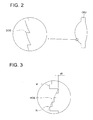
- diffractive structure DOE of a blazed type as shown in Fig. 2
- superposition type diffractive structure HOE wherein plural ring-shaped zones R having therein a stair-shaped structure are arranged with their centers placed on the optical axis, as shown in Fig. 3.
- a laser light flux with wavelength ⁇ 1 enters the superposition type diffractive structure HOE
- an optical path difference of k x ⁇ 1 ( ⁇ m) is generated between adjoining steps, and no phase difference is given substantially to the laser light flux with wavelength ⁇ 1 which, therefore, is transmitted as it is without being diffracted.
- a light flux transmitted as it is without being given a phase difference substantially by the superposition type diffractive structure is called a zero-order diffracted light.
- k 2
- the light flux with wavelength ⁇ 2 is made by the superposition type diffractive structure HOE to be a diffracted light that is diffracted in the direction of the first order.
- a diffraction efficiency of the first order diffracted light of the laser light flux with wavelength ⁇ 2 in this case is 87.5% which represents a sufficient amount of light for conducting recording/reproducing of information for DVD.
- the optical pickup apparatus PU shown in the present embodiment causes the light flux with wavelength ⁇ 1 to enter the objective optical element OBJ as a parallel light and causes the light flux with wavelength ⁇ 3 to enter the objective optical element OBJ as a divergent light by changing the distance in the optical axis direction between the first lens and the second lens by moving the first lens in the optical axis direction, depending on the occasion where the light flux with wavelength ⁇ 1 or ⁇ 2 passes and the occasion where the light flux with wavelength ⁇ 3 passes. Due to this, optical system magnifications for the objective optical element OBJ respectively for the light flux with wavelength 1 and the light flux with wavelength 3 are made to be different, and spherical aberration caused by a difference of protective layer thickness between AOD and CD can be corrected.
- optical magnification of a divergent angle-converting element it is preferable for the optical magnification of a divergent angle-converting element to satisfy the following (1) - (3). -1/100 ⁇ ml ⁇ 1/100 -1/100 ⁇ m2 ⁇ 1/100 1/3 ⁇ m3 ⁇ 1
- the light flux with wavelength ⁇ 2 emerges from divergent angle-converting element OC as a parallel light in the present embodiment, it is also possible to employ, without being limited to the foregoing, the structure wherein the light flux with wavelength ⁇ 2 emerges as a divergent light and the structure wherein the light flux with wavelength ⁇ 2 emerges as a divergent light a converged light.
- a divergent angle of the light flux with wavelength 7 ⁇ 3 emerging from the divergent angle-converting element OC needs to be greater than that of the light flux with wavelength ⁇ 2, for securing the function to correct spherical aberration caused by a difference of protective layer thickness between AOD and CD.
- the second light source LD2 and the third light source LD3 can be arranged separately, without being limited to the structure stated above.
- the optical element constituting the optical system of the optical pickup apparatus PU can be used commonly by the second light flux and the third light flux, which can realize downsizing of the optical pickup apparatus PU and reduction of the number of parts.
- the first lens L1 is moved in the optical axis direction toward a light source LD1 when using CD in the present embodiment, the first lens L1 may also be moved toward the optical information recording medium , or the second lens L2 may be moved.
- the second lens L2 when using CD, the second lens L2 is moved in the optical axis direction to the optical information recording medium side. Due to this, the distance between the second lens and the first lens L1 in the case of using CD is made to be smaller than the distance between the second lens L2 and the first lens L1 in the case of using AOD and DVD.
- AOD or DVD is a multi-layer disc such as a two-layer disc structured by laminating at least a transparent protective layer, the first information recording surface, an intermediate layer and the second information recording surface, in this order from the light source side in the optical axis direction, spherical aberration resulting from a focus jump between layers in the course of recording/reproducing needs to be corrected.
- a method of correcting this spherical aberration there is given the method to change an angle of incidence of a light flux entering the objective lens OBJ.
- a distance of movement of the first lens or the second lens in the case of using CD is within a range of 1 mm - 3 mm.
- a distance of movement of the first lens or the second lens for correcting spherical aberration resulting from the focus jump in multi-layer disc is within a range of 0.1 mm - 0.5 mm.
- the "distance of movement” mentioned here is naturally an amount of a change of the lens distance when the first or second lens is moved, which is different from an actual amount of movement of each lens.
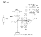
- Fig. 4 is a diagram showing schematically the structure of the first optical pickup apparatus PU that can conduct recording/reproducing of information properly for any of AOD (first optical information recording medium ), DVD (second optical information recording medium) and CD (third optical information recording medium).
- the combination of the wavelength, the thickness of a protective layer and the numerical aperture is not limited to the foregoing.
- Optical pickup apparatus PU is composed of light source unit LU wherein violet semiconductor laser LD1 (first light source) that emits a laser light flux (first light flux) with wavelength of 407 nm emitted in the case of conducting recording/reproducing of information for AOD, red semiconductor laser LD2 (second light source) that emits a laser light flux (second light flux) with wavelength of 655 nm emitted in the case of conducting recording/reproducing of information for DVD, and infrared semiconductor laser LD3 (third light source) that emits laser light flux (third light flux) with wavelength of 785 nm emitted in the case of conducting recording/reproducing of information for CD are all united solidly, photodetector PD commonly for the first, second and third light fluxes, divergent angle-converting element OC through which the first - third light fluxes pass, objective lens (objective optical element) OBJ having a function to converge each light flux on each of information recording surfaces RL1, RL2 and RL3, astigmatic difference
- the divergent angle-converting element OC is composed of two plastic lenses representing the first lens L1 having positive refracting power and the second lens L2 having negative refracting power which is arranged on the light source unit LU side from the first lens L1.one or both of the first lens L1 and the second lens L2 is made of plastic.
- a divergent angle of each light flux is changed by changing a distance in the optical axis direction between the first lens and the second lens, by shifting a position of the first lens L1 depending on the occasion when a light flux with wavelength ⁇ 1 or ⁇ 2 passes or on the occasion when a light flux with wavelength ⁇ 3 passes, which will be explained in detail later.
- a diffractive structure is provided on the objective lens OBJ.
- the uniaxial actuator AC1 When conducting recording/reproducing of information for AOD on the optical pickup apparatus PU, the uniaxial actuator AC1 is driven so that the first lens L1 may be moved up to position P1 on the optical axis.
- violet semiconductor laser LD1 in light source unit LU is driven to emit light.
- a divergent light flux emitted from the violet semiconductor laser LD1 is branched by astigmatic difference plate AP, and most rays of light thereof pass through divergent angle-converting element OC, and a part thereof takes a course to monitor sensor lens MSEN.
- a ray of light emitted from the divergent angle-converting element OC as divergent light is deflected by a mirror and arrives at wavelength plate WP and objective optical element OBJ.
- the ray of light which has passed through the monitor sensor lens MSEN is converged on the monitor photodetector to be used for adjustment of output of light source unit LU.
- Focusing and tracking are conducted for the objective optical element OBJ by the biaxial actuator AC2 arranged on the circumference of the objective optical element OBJ.
- a reflected light flux modulated by information pits on the information recording surface RL1 passes again the objective optical element OBJ, 1/4 wavelength plate WP, divergent angle-converting element OC and an astigmatic difference plate, and is converged on a light-receiving surface of photodetector PD.
- information recorded on AOD can be read by the use of output signals of the photodetector PD.
- the uniaxial actuator AC1 when conducting recording/reproducing of information for DVD, the uniaxial actuator AC1 is driven so that the first lens L1 may be moved up to position P20 on the optical axis.
- the first lens at this point of time is shown with one-dot chain lines in Fig. 4. Namely, the distance between the first lens L1 and the second lens L2 in the case where the first lens is located at position P20 is smaller than the distance between the first lens L1 and the second lens L2 in the case where the first lens L1 is located at position P10.
- red semiconductor laser LD2 positioned in light source unit LU is driven to emit light.
- a divergent light flux emitted from the red semiconductor laser LD2 is branched by astigmatism plate AP in the same way as in the case of AOD, and most rays of light thereof pass through divergent angle-converting element OC, and a part thereof takes a course to monitor sensor lens MSEN.
- a ray of light emerging from the divergent angle-converting element OC as converged light is deflected by a mirror and arrives at wavelength plate WP and objective optical element OBJ.
- the ray of light which has passed through the monitor sensor lens MSEN is converged on the monitor photodetector to be used for adjustment of output of light source unit LU.
- a diffracted light in the prescribed diffraction order number of the second light flux generated by diffracting actions of the diffractive structure of the objective optical element OBJ is converged on the information recording surface RL2 through protective layer PL2 of DVD, thus, the second light-converged spot is formed.
- Chromatic aberration of this second light-converged spot is controlled to be within a range that is needed for reproducing and/or recording of information, and specifically, an absolute value of the chromatic aberration of the second light-converged spot is controlled to be 0.25 ⁇ m/nm or less.
- Focusing and tracking are conducted for the objective optical element OBJ by the biaxial actuator AC2 arranged on the circumference of the objective optical element OBJ.
- a reflected light flux modulated by information pits on the information recording surface RL2 passes again the objective optical element OBJ, 1/4 wavelength plate WP, divergent angle-converting element OC and an astigmatic difference plate, and is converged on a light-receiving surface of photodetector PD.
- information recorded on DVD can be read by the use of output signals of the photodetector PD.
- the uniaxial actuator AC1 when conducting recording/reproducing of information for CD, the uniaxial actuator AC1 is driven so that the first lens L1 may be moved up to position P30 on the optical axis.
- the first lens at this point of time is shown with dotted lines in Fig. 4.
- the distance between the first lens L1 and the second lens L2 in the case where the first lens L1 is located at position P30 is smaller than the distance between the first lens L1 and the second lens L2 in the case where the first lens L1 is located at position P20.
- infrared semiconductor laser LD3 positioned in light source unit LU is driven to emit light.
- a divergent light flux emitted from the infrared semiconductor laser LD3 is branched by astigmatism plate AP in the same way as in the case of AOD, and most rays of light thereof pass through divergent angle-converting element OC, and a part thereof takes a course to monitor sensor lens MSEN.
- a ray of light emerging from the divergent angle-converting element OC as divergent light is deflected by a mirror and arrives at wavelength plate WP and objective optical element OBJ.
- the ray of light which has passed through the monitor sensor lens MSEN is converged on the monitor photodetector to be used for adjustment of output of light source unit LU.
- a diffracted light in the prescribed diffraction order number of the third light flux generated by diffracting actions of the diffractive structure of the objective optical element OBJ is converged on the information recording surface RL2 through protective layer PL3 of CD, thus, the third light-converged spot is formed.
- Chromatic aberration of this third light-converged spot is controlled to be within a range that is needed for reproducing and/or recording of information, and specifically, an absolute value of the chromatic aberration of the third light-converged spot is controlled to be 0.25 ⁇ m/nm or less.
- Focusing and tracking are conducted for the objective optical element OBJ by the biaxial actuator AC2 arranged on the circumference of the objective optical element OBJ.
- a reflected light flux modulated by information pits on the information recording surface RL3 passes again the objective optical element OBJ, 1/4 wavelength plate WP, divergent angle-converting element OC and an astigmatic difference plate, and is converged on a light-receiving surface of photodetector PD.
- information recorded on CD can be read by the use of output signals of the photodetector PD.
- the distance between the first lens L1 and the second lens L2 are arranged so that the distance between them may be different for all occasions of using AOD, DVD and CD, and thereby, optical system magnifications of the objective optical element OBJ are made to be different for the light fluxes each having each of wavelength ⁇ 1, wavelength ⁇ 2 and wavelength ⁇ 3, which corrects spherical aberration caused by a difference of wavelength between AOD and DVD and spherical aberration caused by a difference of wavelength and of protective layer thickness between AOD and CD.
- a position of a light emission point varies slightly depending on the wavelength.
- the astigmatic difference plate AP may be replaced with a beam splitter, it is necessary to provide a sensor lens that converges light on a sensor, in that case.
- a monitor sensor lens is changed to a hologram lens, because an amount of light received can be less for the purpose of monitoring, it can be arranged at an appropriate angle that matches a size of an optical pickup apparatus.
- the light source unit wherein three light sources are united solidly is used in the present embodiment, it is also possible to use a two-laser one-package wherein a light source for AOD and a light source for DVD and CD which has spread generally are unitized.
- the objective optical element OBJ is a plastic single lens of a double-aspherical type having a function to converge the first - third light fluxes respectively on information recording surfaces RL1 - RL3 of optical discs.
- the present explanation has been given with an example of AOD as the first optical information recording medium in the First and Second Embodiments, the invention is not limited to this, and can also be applied to other high density optical discs including, for example, an optical disc having image-side numerical aperture (NA) of about 0.85 and protective layer thickness of about 0.1 mm.
- NA image-side numerical aperture
- the structure may also be one wherein the divergent angle-converting element is driven by an actuator to the appropriate position, in accordance with distinction signals obtained by distinguishing the types of optical discs.
- the divergent angle-converting element is adjusted to be at an appropriate position in accordance with disc information obtained from the discriminating means by driving the actuator mentioned above, or the collimator is driven and adjusted at the timing of emission from an appropriate laser light source in accordance with the disc information.
- Lens movement in the case where the divergent angle-converting element is composed of plural lenses includes an occasion wherein either one lens is moved toward the object side or toward the optical information recording medium side so that a distance between both lenses may be changed, and an occasion wherein lenses are moved together toward the object side or toward the optical information recording medium side without while the distance between lenses is kept unchanged.
- An optical pickup apparatus of the present example is of the structure wherein the first lens L1 is moved toward the light source side when CD is used, in the same way as in the optical pickup apparatus PU shown in Fig. 1, but, it is not equipped with beam shaping element BSH.
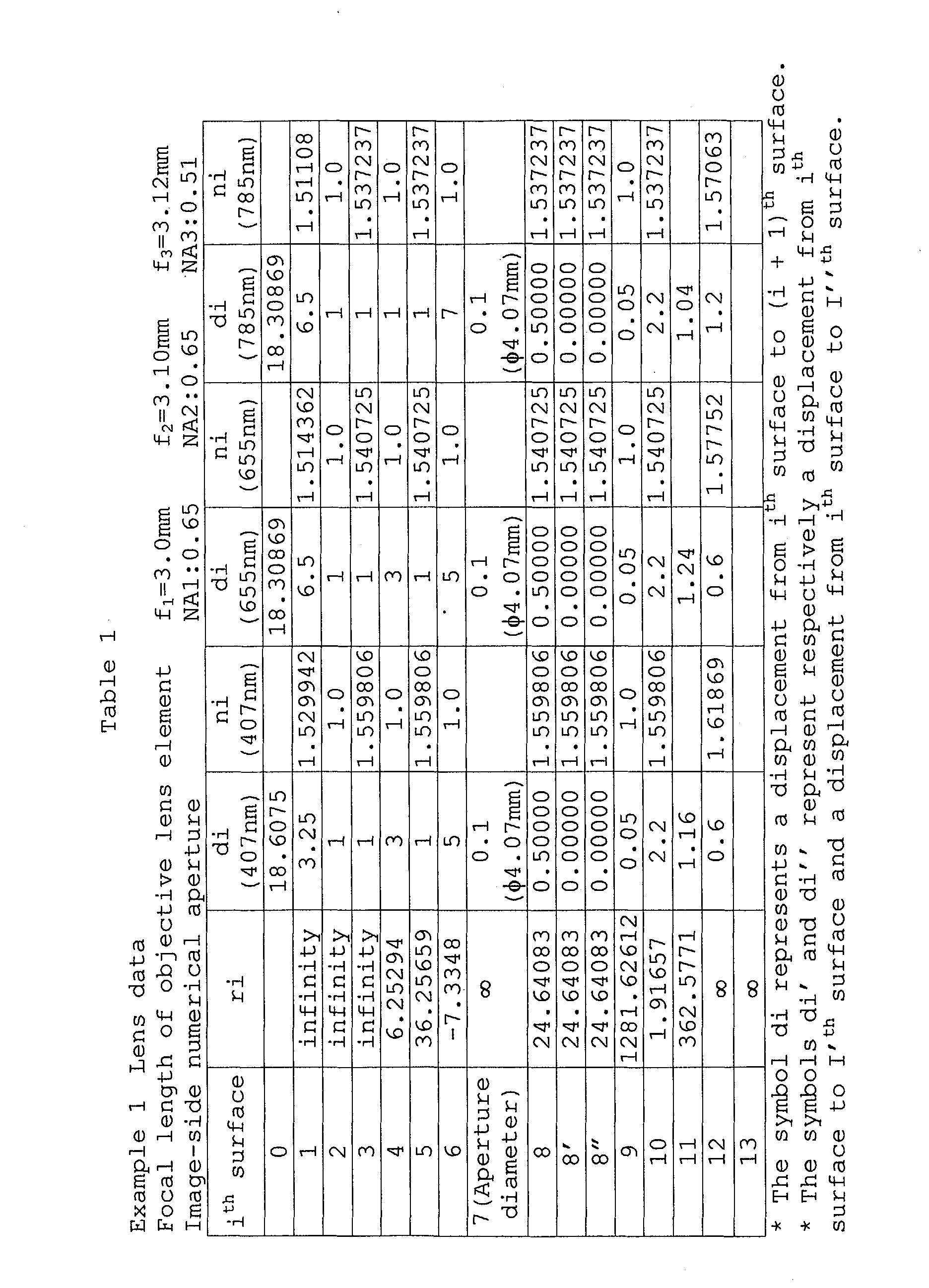
- Lens data of each optical element are shown in Table 1 and Table 2.
- Aspheric surface data Optical element Third surface Aspheric surface coefficient ⁇ -1.0000 x E+2 A2 -5.4601 x E-3 A4 -1.1061 x E-3 A6 +1.1936 x E-4 A8 -1.5745 x E-6
- the objective optical element OBJ is composed of two combined lenses (first objective lens and second objective lens), and a plane of incidence of the first objective lens is divided into three concentric-circle-shaped areas each having its center on the optical axis (8 th surface, 8 ,th surface and 8" th surface in Table 1), and a blaze-shaped diffractive structure is formed on each area.
- the first and second light fluxes enter the objective optical element as a parallel light, while, the third light flux enters the objective optical element as a divergent light.
- Each of a plane of incidence (third surface) and a plane of emergence (fourth surface) of the first lens L1, a plane of incidence (fifth surface) and a plane of emergence (sixth surface) of the second lens L2, a plane of incidence (8 th surface, 8' th surface and 8" th surface) and a plane of emergence (9 th surface) of the first objective lens, and a plane of incidence (10 th surface) and a plane of emergence (11 th surface) of the second objective lens is formed to be an aspheric surface which is prescribed by the numerical expression wherein coefficients shown in Table 1 and Table 2 are substituted for the following expression (Numeral 1) and is symmetrical axially about optical axis L.
- X (h) represents an axis in the optical axis direction (a traveling direction of light is assumed to be positive)
- ⁇ represents a conic constant
- a 2i represents an aspheric surface coefficient.
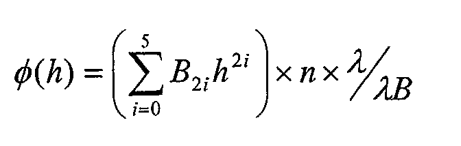
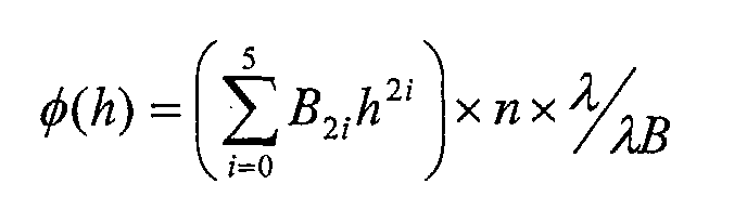
- a pitch of the diffractive ring-shaped zones is prescribed by the numerical expression wherein a coefficient shown in Table 2 is substituted for the optical path difference function of Numeral 2.
- B 2i represents a coefficient of the optical path difference function
- ⁇ represents a using wavelength
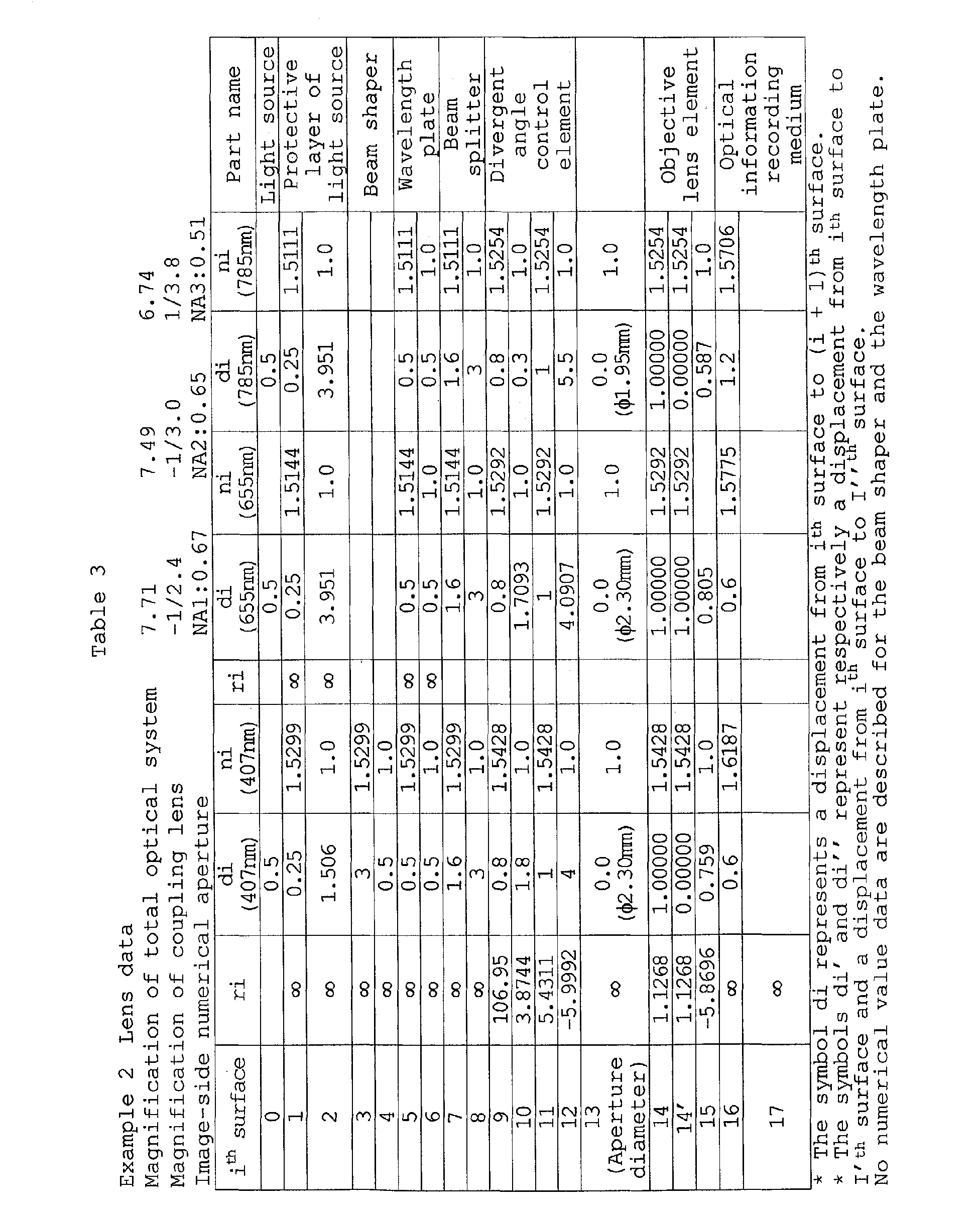
- Table 3 shows a specific example of a divergent angle-converting element and an objective optical element which are fitted to the optical pickup apparatus shown in Fig. 4.
- Divergent angle-converting element 9 th surface Aspheric surface coefficient ⁇ -5.5906 E+01 A1 2.8997 E-03 A2 -1.1716 E-03 A2 -1.1 716 E - 0 3 10 th surface Aspheric surface coefficient ⁇ -5.0110 E+00 A1 5.7774 E-03 A2 -1.3980 E-03 11 th surface Aspheric surface coefficient ⁇ -3.9979 E+00 A1 8.3928 E-04 A2 -7.2950 E-05 7.
- Table 3 is different from Fig. 4 on the points that a two-laser one-package wherein a light source for AOD and a light source for DVD and CD which has spread generally are unitized is used as a light source, a beam shaper is assumed to be arranged on an optical path used exclusively for AOD and a wavelength plate for focus signals is arranged, it is possible to use the divergent angle-converting element and the objective optical element for the embodiment shown in Fig. 4.
- Convergent light, convergent light and divergent light of AOD, DVD and CD enter the objective optical element.
- the objective optical element is a plastic single lens, and a diffractive structure is provided on its total surface on the light source side.
- a diffractive action for light of CD on the area used for recording and reproducing for CD is different from that on an area outside the aforesaid area, and light passing through the outer area is not converged on an information recording surface. Therefore, specified numerical apertures for all rays of light are satisfied by only one diaphragm located at the light source side on the objective optical element.
- Each of a plane of incidence (third surface) and a plane of emergence (fourth surface) of the first lens L1, a plane of incidence (fifth surface) and a plane of emergence (sixth surface) of the second lens L2, a plane of incidence (8 th surface, 8' th surface and 8'' th surface) and a plane of emergence (9 th surface) of the first objective lens, and a plane of incidence (10 th surface) and a plane of emergence (11 th surface) of the second objective lens is formed to be an aspheric surface which is prescribed by the numerical expression wherein coefficients shown in Table 3 are substituted for the following expression (Numeral 1) and is symmetrical axially about optical axis L.
- X (h) represents an axis in the optical axis direction (a traveling direction of light is assumed to be positive)
- K represents a conic constant
- a 2i represents an aspheric surface coefficient.
- a pitch of the diffractive ring-shaped zones is prescribed by the numerical expression wherein a coefficient shown in Table 3 is substituted for the optical path difference function of Numeral 2.
- the objective optical element does not have a function for correcting chromatic aberration of AOD, it is possible to cause the objective optical element to have the function by utilizing diffracting actions.
- the optical magnification of the divergent angle-converting element satisfies the following expressions (4) - (6). -1/2 ⁇ ml ⁇ -1/5 -2/5 ⁇ m2 ⁇ -1/100 1/100 ⁇ m3 ⁇ 1/3
- the light flux with wavelength ⁇ 3 is assumed to emerge from divergent angle-converting element OC with a divergent angle that is greater than that for the light flux with wavelength ⁇ 2, for securing a function to correct spherical aberration caused by a difference of protective layer thickness between AOD and CD.
- the present invention makes it possible to obtain an optical pickup apparatus that has compatibility for information recording media each having a different protective layer, especially compatibility for AOD, DVD and CD, and can correct spherical aberration caused by a difference of protective layer for AOD and CD.
Landscapes
- Physics & Mathematics (AREA)
- Optics & Photonics (AREA)
- Optical Head (AREA)
Abstract
Description
a first light source emitting a light flux having a wavelength λ1 for recording and/or reproducing information for a first optical information recording medium having protective layer thickness t1,
a second light source emitting a light flux having a wavelength λ2 (λ1 < λ2) for recording and/or reproducing information for a second optical information recording medium having protective layer thickness t2 (0.8t1 ≤ t2 ≤ 1.2t1),
a third light source emitting a light flux having a wavelength λ3 (1.6 λ1 ≤ λ3 < 2λ1, λ2 < λ3) for recording and/or reproducing information for a third optical information recording medium having protective layer thickness t3 (1.9t1 ≤ t3 ≤ 2.1t1),
a divergent angle-converting element arranging in a common optical path through which light flux respectively having the wavelengths λ1, λ2 and λ3 pass and constituting movably to change a position in an optical axis direction,
an objective optical element for condensing a light flux having the wavelengths λ1, λ2 and λ3 which pass through the divergent angle-converting element from the first,second and the third light souces,onto the information recording medias,
wherein a position of the divergent angle-converting element on the occasion when light flux having the wavelength λ1 or λ2 passes through is different from a position of the divergent angle-converting element on the occasion the light flux having the wavelength λ3 passes through the divergent angle-converting element.
a first light source emitting light flux having a wavelength λ1 for recording and/or reproducing information for a first optical information recording medium having protective layer thickness t1,
a second light source emitting light flux having a wavelength λ2 (λ1 < λ2) for recording and/or reproducing information for a second optical information recording medium having protective layer thickness t2 (0.8t1 ≤ t2 ≤ 1.2t1),
a third light source emitting light flux having a wavelength λ3 (1.6 λ1 <- λ3 < 2λ1, λ2 < λ3) for recording and/or reproducing information for a third optical information recording medium having protective layer thickness t3 (1.9t1 ≤ t3 ≤ 2.1t1),
a divergent angle-converting element arranging in a common optical path through which the light fluxes respectively having wavelength λ1, λ2 and λ3 pass and constituting movably to change a position in an optical axis direction and emerging light fluxes having wavelength λ1 and λ2 as a parallel light,
an objective optical element for condensing the light flux having the wavelengths λ1, λ2 and λ3 which pass through the divergent angle-converting element from the first,second and the third light souces,onto the information recording media and wherein the objective optical element having an diffractive structure on an at least one optical surface,
wherein a position of the divergent angle-converting element on the occasion when light flux having the wavelength λ1 or λ2 passes through is different from a position of the divergent angle-converting element on the occasion when light flux having the wavelength λ3 passes through the divergent angle-converting element.
a first light source emitting a light flux having wavelength λ1 for recording and/or reproducing information for a first optical information recording medium having storage capacity S1,
a second light source emitting a light flux having wavelength λ2 (λ1 < λ2) for recording and/or reproducing information for a second optical information recording medium having storage capacity S2(S1 > S2),
a third light source emitting a light flux having wavelength λ3 (1.6 λ1 ≤ λ3 < 2λ1, λ2 < λ3) for recording and/or reproducing information for a third optical information recording medium having storage capacity S3(S2 > S3),
a divergent angle-converting element arranging in a common optical path through which light flux respectively having the wavelengths λ1, λ2 and λ3 pass and constituting movably to change a position in an optical axis direction,
an objective optical element for condensing light flux having the wavelengths λ1, λ2 and λ3 which pass through the divergent angle-converting element from the first,second and the third light souces, onto the information recording media respectively,
wherein a position of the divergent angle-converting element on the occasion when light flux having the wavelength λ1 or λ2 passes through is different from the position on the occasion light flux having the wavelength λ3 passes through the divergent angle-converting element.
a first light source emitting a light flux having a wavelength λ1 for reproducing and/or recording information onto a first information recording medium,
a second light source emitting light flux having a wavelength λ2 (λ1 < λ2) for reproducing and/or recording information onto a second information recording medium which is different from kind of the first information recording medium,
a third light source emitting light flux having a wavelength λ3 (λ1 ≤ λ3 < 2λ1, λ2 < λ3) for reproducing and/or recording information onto a third information recording medium which is different from kind of the first and the second information recording media,
a divergent angle-converting element arranging in a common optical path through which light flux respectively having the wavelengths λ1, λ2 and λ3 pass,
an objective optical element for condensing light flux having the wavelengths λ1, λ2 and λ3 which pass through the divergent angle-converting element from the first,second and the third light souces,onto the information recording media respectively,
- LD
- Light source
- OBJ
- Objective lens
- PU
- Optical pickup apparatus
- RL
- Information recording surface
- OC
- Divergent angle-converting element
- L1
- First lens
- L2
- Second lens
| Aspheric surface data Optical element | |
| Third surface | |
| Aspheric surface coefficient | κ -1.0000 x E+2 |
| A2 -5.4601 x E-3 | |
| A4 -1.1061 x E-3 | |
| A6 +1.1936 x E-4 | |
| A8 -1.5745 x E-6 | |
| Fourth surface | |
| Aspheric surface coefficient | κ -6.5960 x E-0 |
| A2 -3.1231 x E-3 | |
| A4 -1.1074 x E-3 | |
| A6 +2.2556 x E-4 | |
| A8 -1.7113 x E-5 | |
| Fifth surface | |
| Aspheric surface coefficient | κ +2.9561 x E-0 |
| A2 -2.2064 x E-3 | |
| A4 -1.8408 x E-4 | |
| A6 +1.4728 x E-5 | |
| A8 -6.4263 x E-7 | |
| Sixth surface | |
| Aspheric surface coefficient | κ +2.3793 x E-0 |
| A2 -8.6964 x E-4 | |
| A4 +1.5721 x E-4 | |
| A6 +9.6871 x E-6 | |
| A8 +5.1240 x E-7 |
| Objective optical element | |
| Eighth surface 0 mm ≤ h < 1.662 mm (AOD: 10th order DVD: 6th order CD: 5th order Blazed wavelength 1 mm) | |
| Aspheric surface coefficient | κ -2.4929 x E+1 |
| A2 -1.5119 x E-3 | |
| A4 +3.6795 x E-4 | |
| A6 +7.4902 x E-5 | |
| A8 -1.0866 x E-5 | |
| Optical path difference function | B2 -3.0581 x E-0 |
| B4 -1.3892 x E-1 | |
| B6 +1.1519 x E-2 B8 +2.7576 x E-3 | |
| B10 -1.2445 x E-3 | |
| 8'th surface 1.662 mm ≤ h < 1.95 mm (AOD: 5th order DVD: 3rd order Blazed wavelength 1 mm) | |
| Aspheric surface coefficient | κ -2.4929 x E+1 |
| A2 -1.5119 x E-3 | |
| A4 +3.6795 x E-4 | |
| A6 +7.4902 x E-5 | |
| A8 -1.0866 x E-5 | |
| Optical path difference function | B2 -6.1161 x E-0 |
| B4 -2.7785 x E-1 | |
| B6 +2.3039 x E-2 | |
| B8 +5.5152 x E-3 | |
| B10 -2.4891 x E-3 | |
| 8"th surface 1.95 mm ≤ h (AOD: mm) 4th order Blazed wavelength 1 | |
| Aspheric surface coefficient | κ -2.4929 x E+1 |
| A2 -1.5119 x E-3 | |
| A4 +3.6795 x E-4 | |
| A6 +7.4902 x E-5 | |
| A8 -1.0866 x E-5 | |
| Optical path difference function | B2 -7.6451 x E-0 |
| B4 -3.4731 x E-1 | |
| B6 +2.8799 x E-2 | |
| B8 +6.8940 x E-3 | |
| B10 -3.1113 x E-3 | |
| 9th surface | |
| Aspheric surface coefficient | κ -1.1391 x E+18 |
| A2 -8.2648 x E-4 | |
| A4 +3.8280 x E-4 | |
| A6 +3.6185 x E-5 | |
| A8 +1.2638 x E-6 | |
| 10th surface | |
| Aspheric surface coefficient | κ -4.0404 x E-1 |
| A2 +2.1403 x E-3 | |
| A4 +2.5829 x E-4 | |
| A6 +3.6091 x E-5 | |
| A8 -1.7376 x E-5 | |
| A10 +1.5482 x E-5 | |
| A12 -2.3082 x E-6 | |
| 11th surface | |
| Aspheric surface coefficient | κ -9.7293 x E+4 |
| A2 +2.2580 x E-2 | |
| A4 +1.7235 x E-2 | |
| A6 +1.5069 x E-2 | |
| A8 -8.8847 x E-3 | |
| A10 +2.7310 x E-3 | |
| A12 -3.3806 x E-4 |

| Divergent angle-converting element | |
| 9th surface | |
| Aspheric surface coefficient | κ -5.5906 E+01 |
| A1 2.8997 E-03 | |
| A2 -1.1716 E-03 A2 -1.1 716 E - 0 3 | |
| 10th surface | |
| Aspheric surface coefficient | κ -5.0110 E+00 |
| A1 5.7774 E-03 | |
| A2 -1.3980 E-03 | |
| 11th surface | |
| Aspheric surface coefficient | κ -3.9979 E+00 |
| A1 8.3928 E-04 | |
| A2 -7.2950 E-05 7. 2 9 5 0 E - 0 5 | |
| 12th surface | |
| Aspheric surface coefficient | κ -4.1970 E+00 |
| A1 -1.3268 E-03 | |
| A2 4.2864 E-05 |
| Objective optical element | |
| 14th surface (0mm ≤ h ≤ 0.987mm) | |
| Aspheric surface coefficient | κ -3.5439 E-01 |
| A1 9.3103 E-04 | |
| A2 -2.2020 E-02 | |
| A3 1.9563 E-02 | |
| A4 2.1640 E-03 | |
| A5 -9.0776 E-03 | |
| A6 8.9517 E-04 | |
| Optical path difference function (HD DVD: 10th order DVD :6th order CD: 5th order Manufacture wavelength 407 nm) | B2 -5.4634 E-04 |
| B4 -5.2429 E-05 | |
| B6 -3. 6016 E-04 | |
| B8 7.4264 E-04 | |
| B10 -3.9449 E-04 | |
| 14'th surface (0.987mm < h) | |
| Aspheric surface coefficient | κ -3.5439 E-01 |
| A1 9.3103 E-04 | |
| A2 -2.2020 E-02 | |
| A3 1.9563 E-02 | |
| A4 2.1640 E-03 | |
| A5 -9.0776 E-03 | |
| A6 8.9517 E-04 | |
| Optical path difference function (HD DVD: 5th order DVD:3rd order Manufacture wavelength 407 nm) | B2 -1.0927 E-03 |
| B4 -1.0486 E-04 | |
| B6 -7.2032 E-04 | |
| B8 1.4853 E-03 | |
| B10 -7.8897 E-04 | |
| 15th surface | |
| Aspheric surface coefficient | κ -2.8046 E+02 |
| A1 -4.6928 E-02 | |
| A2 1.5971 E-01 | |
| A3 -1.8631 E-01 | |
| A4 1.0705 E-01 | |
| A5 -2.6542 E-02 | |
| A6 1.1769 E-03 |

Claims (36)
- An optical pickup apparatus comprising;
a first light source emitting light flux having a wavelength λ1 for recording and/or reproducing information for a first optical information recording medium having protective layer thickness t1,
a second light source emitting light flux having a wavelength λ2 (λ1 < λ2) for recording and/or reproducing information for a second optical information recording medium having protective layer thickness t2 (0.8t1 ≤ t2 ≤ 1.2t1),
a third light source emitting light flux having a wavelength λ3 (1.6 λ1 ≤ λ3 < 2λ1, λ2 < λ3) for recording and/or reproducing information for a third optical information recording medium having protective layer thickness t3 (1.9t1 ≤ t3 ≤ 2.1t1),
a divergent angle-converting element arranged in a common optical path through which light flux respectively having the wavelengths λ1, λ2 and λ3 pass and having a movable position in an optical axis direction,
an objective optical element for condensing light flux having the wavelengths λ1, λ2 and λ3 which pass through the divergent angle-converting element from the first,second and the third light sources, onto the information recording media respectively,
wherein the position of the divergent angle-converting element on the occasion when the light flux having wavelength λ1 or λ2 passes through is different from the position on the occasion the light flux λ3 passes through the divergent angle-converting element. - The optical pickup apparatus according to Claim 1,
wherein the divergent angle-converting element comprises a first lens and a second lens arranged on the light source side from the first lens, and wherein a distance between the first lens and the second lens on the occasion when light flux having the wavelength λ1 passes through the first and the second lenses is different from that of on the occasion when light flux having the wavelength λ3 passes through the first and the second lenses. - The optical pickup apparatus according to Claim 2,
wherein the distance between the first lens and the second lens on the occasion where the light flux having wavelength λ3 passes through the first and the second lenses is obtained by moving the first lens toward the light source side. - The optical pickup apparatus according to Claim 2,
wherein the distance between the first lens and the second lens on the occasion where the light flux having wavelength λ3 passes through the first and the second lenses is obtained by moving the second lens toward the objective optical element side. - The optical pickup apparatus according to Claim 2, 3 or 4
wherein at least one of the first and the second optical information recording media comprises two recording layers and an intermediate layer interposed between the two recording layers, and wherein the divergent angle-converting element corrects spherical aberration caused by a thickness of the intermediate layer by moving the first lens toward the light source side. - The optical pickup apparatus according to Claim 2, 3 or 4
wherein at least one of the first and the second optical information recording media comprises two recording layers and an intermediate layer interposed between the two recording layers, and wherein the divergent angle-converting element corrects spherical aberration caused by a thickness of the intermediate layer by moving the second lens toward the objective optical element side. - The optical pickup apparatus according to Claim 5,
wherein a distance of movement L (mm) of the first lens is within a range of 0.1 ≤ L2 ≤ 0.5. - The optical pickup apparatus according to Claim 6,
wherein a distance of movement L2 (mm) of the second lens is within a range of 0.1 ≤ L2 ≤ 0.5. - The optical pickup apparatus according to any one of
Claims 2 to 8 wherein the first lens has a positive refracting power and the second lens has a negative refracting power. - The optical pickup apparatus according to any one of the
preceding claims, wherein a focal length t (mm) of the divergent angle-converting element for the light flux having the wavelength λ1 satisfies 25 ≤ t ≤ 35. - The optical pickup apparatus according to any one of the
preceding claims, wherein the divergent angle-converting element is made of plastic. - The optical pickup apparatus according to any one of the
preceding claims, wherein a focal length t2 (mm) of the objective optical element for a light flux having wavelength λ1 satisfies 1.5 ≤ t2 ≤ 4.0. - The optical pickup apparatus according to any one of the
preceding claims, wherein a numerical aperture NA1 on an image side of the objective optical element for a light flux having wavelength λ1 satisfies 0.63 ≤NA1 ≤ 0.67 ≤ 0.67. - The optical pickup apparatus according to any one of the
preceding claims, wherein a numerical aperture NA2 on an image side of the objective optical element for a light flux with wavelength λ2 satisfies 0.59 ≤ NA2 ≤ 0.67. - The optical pickup apparatus according to any one of the
preceding claims, wherein numerical aperture NA3 on an image side of the objective optical element for a light flux with wavelength λ3 satisfies 0.44 ≤ NA3 ≤ 0.55. - The optical pickup apparatus according to any one of the
preceding claims, wherein a magnification of the objective optical element for a light flux having the wavelength λ3 satisfies - 1/10 ≤ m3 ≤-1/100. - An optical pickup apparatus comprising;
a first light source emitting light flux having a wavelength λ1 for recording and/or reproducing information for a first optical information recording medium having protective layer thickness t1,
a second light source emitting light flux having a wavelength λ2 (λ1 < λ2) for recording and/or reproducing information for a second optical information recording medium having protective layer thickness t2 (0.8t1 ≤ t2 ≤ 1.2t1),
a third light source emitting light flux having a wavelength λ3 (1.6 λ1 ≤ λ3 < 2λ1, λ2 < λ3) for recording and/or reproducing information for a third optical information recording medium having protective layer thickness t3 (1.9t1 ≤ t3 ≤ 2.1t1),
a divergent angle-converting element arranging in a common optical path through which the light fluxes respectively having wavelength λ1, λ2 and λ3 pass and constituting movably to change a position in an optical axis direction and emerging light fluxes having wavelength λ1 and λ2 as a parallel light,
an objective optical element for condensing the light flux having, the wavelengths λ1, λ2 and λ3 which pass through the divergent angle-converting element from the first, the second and the third light souces onto the information recording media respectively and wherein the objective optical element having an diffractive structure on an at least one optical surface,
wherein a position of the divergent angle-converting element on the occasion when the light flux having wavelength λ1 or λ2 passes through is different from the position on the occasion the light flux λ3 passes through the divergent angle-converting element. - An optical pickup apparatus comprising;
a first light source emitting light flux having a wavelength λ1 for recording and/or reproducing information for a first optical information recording medium having storage capacity S1,
a second light source emitting light flux having a wavelength λ2 (λ1 < λ2) for recording and/or reproducing information for a second optical information recording medium having storage capacity S2(S1 > S2),
a third light source emitting light flux having a wavelength λ3 (1.6 λ1 ≤ λ3 < 2λ1, λ2 < λ3) for recording and/or reproducing information for a third optical information recording medium having storage capacity S3(S2 > S3),
a divergent angle-converting element arranging in a common optical path through which light flux respectively having the wavelengths λ1, λ2 and λ3 pass and constituting movably to change a position in an optical axis direction, an objective optical element for condensing the light flux having the wavelengths λ1, λ2 and λ3 which pass through the divergent angle-converting element from the first,second and the third light souces,onto the information recording medias respectively,
wherein a position of the divergent angle-converting element on the occasion when light flux having the wavelength λ1 or λ2 passes through is different from the position on the occasion light flux having the wavelength λ3 passes through the divergent angle-converting element. - The optical pickup apparatus according to Claim 18,
wherein the divergent angle-converting element comprises a first lens and a second lens which arranged the light source side from the first lens, and wherein a distance between the first lens and the second lens on the occasion when light flux having the wavelength λ1 passes through the first and the second lenses which is different from that of on the occasion when light flux having the wavelength λ3 passes through the first and the second lenses. - The optical pickup apparatus according to any one of the
preceding claims, wherein the divergent angle-converting element emerges light flux having the wavelength λ1 as a parallel light and emerges light flux having the wavelength λ2 as a divergent light and emerges light flux having the wavelength λ3 as a divergent light, by changing the position in an optical axis direction. - The optical pickup apparatus according to any one of claims 1 to 19 wherein the divergent angle-converting element emerges light flux having the wavelength λ1 as a convergent light and emerges light flux having the wavelength λ3 as a divergent light, by changing the position in an optical axis direction.
- The optical pickup apparatus according to any one of the
preceding claims, wherein the second light source and the third light source are packaged to be a light source unit. - The optical pickup apparatus according to Claim 19,
wherein the first information recording medium has protective layer thickness t1 the second information recording medium has protective layer thickness t2 that is different from the protective layer thickness t1, and at least one of the first information recording medium and the second information recording medium comprises two recording layers and with an intermediate layer positioned between the two recording layers, and wherein the divergent angle-converting element corrects spherical aberration caused by a thickness of the intermediate layer by moving the first lens toward the light source side. - The optical pickup apparatus according to Claim 19,
wherein the first information recording medium has protective layer thickness t1, the second information recording medium has protective layer thickness t2 that is different from the protective layer thickness t1, and at least one of the first information recording medium and the second information recording medium comprises two recording layers and with an intermediate layer positioned between the two recording layers, and wherein the divergent angle-converting element corrects spherical aberration caused by a thickness of the intermediate layer by moving the second lens toward the objective optical element side. - The optical pickup apparatus according to Claim 2 or 19,
wherein the distance L (mm) of movement of the first lens or the second lens is within a range of 1 ≤ L ≤ 3. - The optical pickup apparatus according to any one of the
preceding claims, wherein the objective optical element comprising a diffractive structure on at least one optical surface. - The optical pickup apparatus according to any one of the
preceding claims, wherein the objective element is composed of a single lens. - The optical pickup apparatus according to any one of
claims 1 to 26, wherein the objective element is composed of a plurality of optical elements. - An optical pickup apparatus comprising;
a first light source emitting a light flux having wavelength λ1 for reproducing and/or recording information onto a first information recording medium,
a second light source emitting light flux having a wavelength λ2 (λ1 < λ2) for reproducing and/or recording information onto a second information recording medium which is different from kind of the first information recording medium,
a third light source emitting a light flux having a wavelength λ3 (λ1 ≤ λ3 < 2λ1, λ2 < λ3) for reproducing and/or recording information onto a third information recording medium which is different from kind of the first and the second information recording media,
a divergent angle-converting element arranging in a common optical path through which light flux respectively having the wavelengths λ1, λ2 and λ3 pass,
an objective optical element for condensing light flux having the wavelengths λ1, λ2 and λ3 which pass through the divergent angle-converting element from the first,second and the third light souces,onto the information recording media respectively,
wherein the divergent angle-converting element varying a position in the optical axis direction such that an optical system magnification of the divergent angle-converting element for light flux having the wavelength λ1 or λ2 is different from that for light flux having the wavelength λ3. - The optical pickup apparatus according to Claim 18 or 29, wherein the first optical information recording medium has the first protective layer thickness t1, the second optical information recording medium has the second protective layer thickness t2 (0.8t1 ≤ t2 ≤ 1.2t1) and the third optical information recording medium has the third protective layer thickness t3 (1.9t1 ≤ t3 ≤ 2.1t1).
- The optical pickup apparatus according to Claim 49,
wherein the divergent angle-converting element comprises a first lens and a second lens , and wherein the optical system magnification can be changed by changing the distance between the first lens and the second lens. - The optical system according to Claim 1, 18 or 29,
wherein the divergent angle-converting element emerges light flux having the wavelength ≤λ1 as a parallel light. - The optical pickup apparatus according to Claim 29,
wherein the divergent angle-converting element emerges light flux having the wavelength λ1 as a parallel light and emerges light fluxes having the wavelength λ2 as a divergent light and emerges light flux having the wavelength λ3 as a divergent light. - The optical pickup apparatus according to Claim 29,
wherein the divergent angle-converting element emerges light flux having the wavelength λ1 as a convergent light and emerges light flux having the wavelength λ3 as a divergent light. - The optical pickup apparatus according to Claim 1, 18, 21
or 29, wherein the divergent angle-converting element emerges light flux having the wavelength λ2 as a parallel light. - A divergent angle-converting element for use in an
optical pickup apparatus as claimed in any one of the preceding claims.
Applications Claiming Priority (4)
| Application Number | Priority Date | Filing Date | Title |
|---|---|---|---|
| JP2003385029 | 2003-11-14 | ||
| JP2003385029 | 2003-11-14 | ||
| JP2004288053 | 2004-09-30 | ||
| JP2004288053 | 2004-09-30 |
Publications (2)
| Publication Number | Publication Date |
|---|---|
| EP1533800A2 true EP1533800A2 (en) | 2005-05-25 |
| EP1533800A3 EP1533800A3 (en) | 2008-02-27 |
Family
ID=34436991
Family Applications (1)
| Application Number | Title | Priority Date | Filing Date |
|---|---|---|---|
| EP04257020A Withdrawn EP1533800A3 (en) | 2003-11-14 | 2004-11-12 | Optical pickup device and optical pickup system using the same |
Country Status (7)
| Country | Link |
|---|---|
| US (1) | US20050105447A1 (en) |
| EP (1) | EP1533800A3 (en) |
| JP (1) | JPWO2005048250A1 (en) |
| KR (1) | KR20050046575A (en) |
| CN (1) | CN100375172C (en) |
| TW (1) | TW200519403A (en) |
| WO (1) | WO2005048250A1 (en) |
Families Citing this family (9)
| Publication number | Priority date | Publication date | Assignee | Title |
|---|---|---|---|---|
| US7426170B2 (en) * | 2002-08-30 | 2008-09-16 | Konica Minolta Opto, Inc. | Objective lens and optical pickup apparatus for reproducing and/or recording information for at least two types of optical discs |
| JP4465200B2 (en) * | 2004-01-20 | 2010-05-19 | Hoya株式会社 | Optical pickup device and objective lens for optical pickup |
| EP1715479A4 (en) * | 2004-02-09 | 2008-09-03 | Pioneer Design Corp | Optical element, optical pickup, and information recording/reproduction device |
| JP3953092B2 (en) * | 2004-04-27 | 2007-08-01 | コニカミノルタオプト株式会社 | Objective lens and optical pickup device |
| KR100651325B1 (en) * | 2004-11-05 | 2006-11-29 | 삼성전기주식회사 | Chromatic Aberration Correction Element and Optical Pick-up Device Using the Same |
| JP4899496B2 (en) * | 2006-01-27 | 2012-03-21 | コニカミノルタオプト株式会社 | Optical pickup device |
| EP2065752A1 (en) * | 2007-11-23 | 2009-06-03 | Koninklijke Philips Electronics N.V. | Optical illumination apparatus for illuminating a sample with a line beam |
| WO2010071125A1 (en) * | 2008-12-17 | 2010-06-24 | コニカミノルタオプト株式会社 | Objective optical element and optical pickup device |
| KR101533373B1 (en) * | 2014-07-16 | 2015-07-02 | (주)아이엠 | Optical Pickup Apparatus |
Family Cites Families (27)
| Publication number | Priority date | Publication date | Assignee | Title |
|---|---|---|---|---|
| JP3266627B2 (en) * | 1991-10-11 | 2002-03-18 | 株式会社日立製作所 | Information playback device |
| US5966362A (en) * | 1995-11-02 | 1999-10-12 | Konica Corporation | Optical system for recording and reproducing for use in optical information recording medium |
| US5818643A (en) * | 1995-11-14 | 1998-10-06 | Mahk Co., Ltd. | Optical objective lens system with variable disk thickness feature |
| JP2000131603A (en) * | 1998-10-22 | 2000-05-12 | Sony Corp | Optical head and recording / reproducing device |
| US6650612B1 (en) * | 1999-03-31 | 2003-11-18 | Matsushita Electric Industrial Co., Ltd. | Optical head and recording reproduction method |
| JP3527685B2 (en) * | 1999-05-10 | 2004-05-17 | シャープ株式会社 | Optical recording / reproducing device |
| JP2001043559A (en) * | 1999-07-30 | 2001-02-16 | Matsushita Electric Ind Co Ltd | Optical head and optical disk device |
| JP4660915B2 (en) * | 2000-05-12 | 2011-03-30 | コニカミノルタホールディングス株式会社 | Optical pickup device |
| EP1968054A3 (en) * | 2000-05-12 | 2012-03-07 | Konica Minolta Opto, Inc. | Optical pick-up apparatus |
| JP2002203333A (en) * | 2000-10-16 | 2002-07-19 | Konica Corp | Objective lens, beam-condensing optical system, and optical pickup device |
| JP4131366B2 (en) * | 2000-10-30 | 2008-08-13 | コニカミノルタホールディングス株式会社 | Objective lens, optical pickup device and recording / reproducing device |
| JP2002170274A (en) * | 2000-12-05 | 2002-06-14 | Pioneer Electronic Corp | Optical pickup |
| JP2002334476A (en) * | 2001-05-14 | 2002-11-22 | Konica Corp | Optical pickup device and recording/reproducing device |
| JP2003067972A (en) * | 2001-05-29 | 2003-03-07 | Nec Corp | Optical head and optical information recording and reproducing device |
| JP3794940B2 (en) * | 2001-06-19 | 2006-07-12 | 株式会社日立製作所 | Objective lens optical system, optical head, and optical information reproducing apparatus |
| JP4817036B2 (en) * | 2001-06-20 | 2011-11-16 | コニカミノルタホールディングス株式会社 | Objective lens, optical pickup device and recording / reproducing device |
| JP3995993B2 (en) * | 2001-06-22 | 2007-10-24 | パイオニア株式会社 | Optical pickup focusing control device and method |
| JP2003109219A (en) * | 2001-09-28 | 2003-04-11 | Toshiba Corp | Optical head device, optical disk device including the optical head device, information recording / reproducing device, and optical disk |
| TWI239520B (en) * | 2001-10-12 | 2005-09-11 | Konica Corp | Objective lens, optical element, optical pick-up apparatus and optical information recording and/or reproducing apparatus equipped therewith |
| TW561466B (en) * | 2001-12-07 | 2003-11-11 | Ind Tech Res Inst | Multi-wavelength optical pickup |
| AU2003201092A1 (en) * | 2002-01-17 | 2003-07-30 | Koninklijke Philips Electronics N.V. | Optical scanning device |
| AU2002354119A1 (en) * | 2002-03-04 | 2003-09-16 | Matsushita Electric Industrial Co., Ltd. | Optical head and optical recording/reproducing device using it, and aberration correction method |
| JP2003296959A (en) * | 2002-03-26 | 2003-10-17 | Samsung Electro Mech Co Ltd | Wavelength selective aperture restriction element, wavelength selective beam splitter and optical pickup device furnished therewith |
| JP2004327003A (en) * | 2002-07-26 | 2004-11-18 | Sharp Corp | Optical pickup |
| US7577077B2 (en) * | 2002-09-05 | 2009-08-18 | Konica Corporation | Optical pickup apparatus and optical element |
| JP2004281008A (en) * | 2003-03-18 | 2004-10-07 | Konica Minolta Holdings Inc | Optical pickup device |
| US7193954B2 (en) * | 2003-03-31 | 2007-03-20 | Konica Minolta Holding, Inc. | Optical pickup device and objective lens for the optical pickup device |
-
2004
- 2004-11-08 JP JP2005515469A patent/JPWO2005048250A1/en active Pending
- 2004-11-08 WO PCT/JP2004/016895 patent/WO2005048250A1/en not_active Ceased
- 2004-11-09 TW TW093134140A patent/TW200519403A/en unknown
- 2004-11-10 US US10/984,777 patent/US20050105447A1/en not_active Abandoned
- 2004-11-11 KR KR1020040092004A patent/KR20050046575A/en not_active Withdrawn
- 2004-11-11 CN CNB2004100929264A patent/CN100375172C/en not_active Expired - Fee Related
- 2004-11-12 EP EP04257020A patent/EP1533800A3/en not_active Withdrawn
Also Published As
| Publication number | Publication date |
|---|---|
| EP1533800A3 (en) | 2008-02-27 |
| CN100375172C (en) | 2008-03-12 |
| US20050105447A1 (en) | 2005-05-19 |
| JPWO2005048250A1 (en) | 2007-05-31 |
| KR20050046575A (en) | 2005-05-18 |
| WO2005048250A1 (en) | 2005-05-26 |
| TW200519403A (en) | 2005-06-16 |
| CN1617243A (en) | 2005-05-18 |
Similar Documents
| Publication | Publication Date | Title |
|---|---|---|
| EP1471514A2 (en) | Optical pickup device, optical information recording and reproducing apparatus, expander lens, coupling lens and chromatic aberration correcting optical element | |
| JP2011014236A (en) | Objective optical system for optical pickup device, optical pickup device, drive device for optical information recording medium, condensing lens, and optical path integration element | |
| US20050219988A1 (en) | Optical pickup apparatus | |
| EP1530208A2 (en) | Optical pick-up apparatus and divergent angle-converting element | |
| JP2003270528A (en) | Method for designing objective lens, objective lens, lens for multiple wavelengths, optical system for multiple wavelengths, optical head, and optical disk device | |
| EP1533800A2 (en) | Optical pickup device and optical pickup system using the same | |
| KR20050031938A (en) | Optical pick-up device and optical information recording reproducing apparatus | |
| US7986595B2 (en) | Optical pickup and optical device for three different types of optical discs | |
| KR20060063943A (en) | Optical pickup | |
| JP2007328886A (en) | Optical pickup device, and optical information recording medium recording and reproducing device | |
| US7206274B2 (en) | Converging optical system of optical pickup device | |
| EP1538613A2 (en) | Optical pickup apparatus and optical information recording and/or reproducing apparatus | |
| CN100479043C (en) | Optical pickup device and divergent angle conversion element | |
| US7710848B2 (en) | Optical pickup apparatus | |
| JP2000028917A (en) | Pickup device for recording and reproducing of optical information recording medium, objective lens, and design method for objective lens | |
| JP4294460B2 (en) | Objective lens, optical pickup device and optical disk device | |
| EP1530207B1 (en) | Optical pickup device with correcting element | |
| EP1569212A2 (en) | Objective optical system, optical pickup apparatus and optical information recording and reproducing apparatus | |
| US20070211604A1 (en) | Optical pickup apparatus | |
| JP3854621B2 (en) | Objective lens | |
| JP3854622B2 (en) | Objective lens | |
| JP2004220760A (en) | Lens, optical system using the same, optical head, and optical disk device | |
| JP2004127510A (en) | Objective lens, optical head and optical disk device | |
| JP2005149618A (en) | Optical pickup device | |
| JP2006012417A (en) | Objective lens, optical head, and optical disk apparatus |
Legal Events
| Date | Code | Title | Description |
|---|---|---|---|
| PUAI | Public reference made under article 153(3) epc to a published international application that has entered the european phase |
Free format text: ORIGINAL CODE: 0009012 |
|
| AK | Designated contracting states |
Kind code of ref document: A2 Designated state(s): AT BE BG CH CY CZ DE DK EE ES FI FR GB GR HU IE IS IT LI LU MC NL PL PT RO SE SI SK TR |
|
| AX | Request for extension of the european patent |
Extension state: AL HR LT LV MK YU |
|
| PUAL | Search report despatched |
Free format text: ORIGINAL CODE: 0009013 |
|
| AK | Designated contracting states |
Kind code of ref document: A3 Designated state(s): AT BE BG CH CY CZ DE DK EE ES FI FR GB GR HU IE IS IT LI LU MC NL PL PT RO SE SI SK TR |
|
| AX | Request for extension of the european patent |
Extension state: AL HR LT LV MK YU |
|
| AKX | Designation fees paid | ||
| REG | Reference to a national code |
Ref country code: DE Ref legal event code: 8566 |
|
| STAA | Information on the status of an ep patent application or granted ep patent |
Free format text: STATUS: THE APPLICATION IS DEEMED TO BE WITHDRAWN |
|
| 18D | Application deemed to be withdrawn |
Effective date: 20080828 |