EP1533792A1 - Thin film magnetic head and method of producing the head - Google Patents
Thin film magnetic head and method of producing the head Download PDFInfo
- Publication number
- EP1533792A1 EP1533792A1 EP03736295A EP03736295A EP1533792A1 EP 1533792 A1 EP1533792 A1 EP 1533792A1 EP 03736295 A EP03736295 A EP 03736295A EP 03736295 A EP03736295 A EP 03736295A EP 1533792 A1 EP1533792 A1 EP 1533792A1
- Authority
- EP
- European Patent Office
- Prior art keywords
- magnetic
- auxiliary yoke
- film
- magnetic head
- yoke
- Prior art date
- Legal status (The legal status is an assumption and is not a legal conclusion. Google has not performed a legal analysis and makes no representation as to the accuracy of the status listed.)
- Withdrawn
Links
Images



Classifications
-
- G—PHYSICS
- G11—INFORMATION STORAGE
- G11B—INFORMATION STORAGE BASED ON RELATIVE MOVEMENT BETWEEN RECORD CARRIER AND TRANSDUCER
- G11B5/00—Recording by magnetisation or demagnetisation of a record carrier; Reproducing by magnetic means; Record carriers therefor
- G11B5/127—Structure or manufacture of heads, e.g. inductive
- G11B5/265—Structure or manufacture of a head with more than one gap for erasing, recording or reproducing on the same track
-
- G—PHYSICS
- G11—INFORMATION STORAGE
- G11B—INFORMATION STORAGE BASED ON RELATIVE MOVEMENT BETWEEN RECORD CARRIER AND TRANSDUCER
- G11B5/00—Recording by magnetisation or demagnetisation of a record carrier; Reproducing by magnetic means; Record carriers therefor
- G11B5/127—Structure or manufacture of heads, e.g. inductive
- G11B5/31—Structure or manufacture of heads, e.g. inductive using thin films
- G11B5/3109—Details
- G11B5/313—Disposition of layers
-
- G—PHYSICS
- G11—INFORMATION STORAGE
- G11B—INFORMATION STORAGE BASED ON RELATIVE MOVEMENT BETWEEN RECORD CARRIER AND TRANSDUCER
- G11B5/00—Recording by magnetisation or demagnetisation of a record carrier; Reproducing by magnetic means; Record carriers therefor
- G11B5/127—Structure or manufacture of heads, e.g. inductive
- G11B5/31—Structure or manufacture of heads, e.g. inductive using thin films
- G11B5/3176—Structure of heads comprising at least in the transducing gap regions two magnetic thin films disposed respectively at both sides of the gaps
- G11B5/3179—Structure of heads comprising at least in the transducing gap regions two magnetic thin films disposed respectively at both sides of the gaps the films being mainly disposed in parallel planes
- G11B5/3183—Structure of heads comprising at least in the transducing gap regions two magnetic thin films disposed respectively at both sides of the gaps the films being mainly disposed in parallel planes intersecting the gap plane, e.g. "horizontal head structure"
-
- G—PHYSICS
- G11—INFORMATION STORAGE
- G11B—INFORMATION STORAGE BASED ON RELATIVE MOVEMENT BETWEEN RECORD CARRIER AND TRANSDUCER
- G11B5/00—Recording by magnetisation or demagnetisation of a record carrier; Reproducing by magnetic means; Record carriers therefor
- G11B5/127—Structure or manufacture of heads, e.g. inductive
- G11B5/33—Structure or manufacture of flux-sensitive heads, i.e. for reproduction only; Combination of such heads with means for recording or erasing only
- G11B5/39—Structure or manufacture of flux-sensitive heads, i.e. for reproduction only; Combination of such heads with means for recording or erasing only using magneto-resistive devices or effects
- G11B5/3903—Structure or manufacture of flux-sensitive heads, i.e. for reproduction only; Combination of such heads with means for recording or erasing only using magneto-resistive devices or effects using magnetic thin film layers or their effects, the films being part of integrated structures
- G11B5/3906—Details related to the use of magnetic thin film layers or to their effects
- G11B5/3916—Arrangements in which the active read-out elements are coupled to the magnetic flux of the track by at least one magnetic thin film flux guide
-
- G—PHYSICS
- G11—INFORMATION STORAGE
- G11B—INFORMATION STORAGE BASED ON RELATIVE MOVEMENT BETWEEN RECORD CARRIER AND TRANSDUCER
- G11B5/00—Recording by magnetisation or demagnetisation of a record carrier; Reproducing by magnetic means; Record carriers therefor
- G11B5/127—Structure or manufacture of heads, e.g. inductive
- G11B5/33—Structure or manufacture of flux-sensitive heads, i.e. for reproduction only; Combination of such heads with means for recording or erasing only
- G11B5/39—Structure or manufacture of flux-sensitive heads, i.e. for reproduction only; Combination of such heads with means for recording or erasing only using magneto-resistive devices or effects
- G11B5/3903—Structure or manufacture of flux-sensitive heads, i.e. for reproduction only; Combination of such heads with means for recording or erasing only using magneto-resistive devices or effects using magnetic thin film layers or their effects, the films being part of integrated structures
- G11B5/3906—Details related to the use of magnetic thin film layers or to their effects
- G11B5/3916—Arrangements in which the active read-out elements are coupled to the magnetic flux of the track by at least one magnetic thin film flux guide
- G11B5/3919—Arrangements in which the active read-out elements are coupled to the magnetic flux of the track by at least one magnetic thin film flux guide the guide being interposed in the flux path
- G11B5/3922—Arrangements in which the active read-out elements are coupled to the magnetic flux of the track by at least one magnetic thin film flux guide the guide being interposed in the flux path the read-out elements being disposed in magnetic shunt relative to at least two parts of the flux guide structure
- G11B5/3925—Arrangements in which the active read-out elements are coupled to the magnetic flux of the track by at least one magnetic thin film flux guide the guide being interposed in the flux path the read-out elements being disposed in magnetic shunt relative to at least two parts of the flux guide structure the two parts being thin films
-
- G—PHYSICS
- G11—INFORMATION STORAGE
- G11B—INFORMATION STORAGE BASED ON RELATIVE MOVEMENT BETWEEN RECORD CARRIER AND TRANSDUCER
- G11B5/00—Recording by magnetisation or demagnetisation of a record carrier; Reproducing by magnetic means; Record carriers therefor
- G11B5/127—Structure or manufacture of heads, e.g. inductive
- G11B5/31—Structure or manufacture of heads, e.g. inductive using thin films
- G11B5/3163—Fabrication methods or processes specially adapted for a particular head structure, e.g. using base layers for electroplating, using functional layers for masking, using energy or particle beams for shaping the structure or modifying the properties of the basic layers
Definitions
- the present invention relates to a magnetic head for writing and/or reading data to/from a magnetic recording medium, and more particularly to a thin-film magnetic head used for a magnetic recording device represented by a hard disk drive (simply referred to as an HDD, hereinafter), and its manufacturing method.
- a hard disk drive as an HDD, hereinafter
- a magnetic head for writing and/or reading data to/from a magnetic disk of an HDD.
- This magnetic head is moved roughly in a radial direction of the magnetic disk by swinging a suspension arm with respect to the rotating magnetic disk.
- this type of magnetic head is formed by depositing a coil, a main pole, a return yoke and the like on a substrate, and polishing an end surface extending in a deposition direction of the deposits. Then, the magnetic head is mounted on the tip of the suspension arm so that the polished end surface, i.e., the end surface in which ends of the main pole and the return yoke are exposed can face the magnetic disk.
- the main pole and the return yoke must be placed as close as possible to each other, and the lengths TH of the opposed portions must be made short.
- the conventional magnetic head is formed by polishing the articles deposited on the substrate by the end surface extending in the deposition direction
- the lengths TH of the opposed portions of the main pole and the return yoke are determined by a degree of the polishing.
- accuracy of polishing work must be increased to set the length of the opposed portion to several tens of nm.
- Objects of the present invention are to provide a thin-film magnetic head capable of increasing a recording density in a magnetic recording medium, and its manufacturing method.
- the present invention has been developed to achieve the above objects.
- a first aspect of the present invention is directed to a thin-film magnetic head comprising a main pole which has a tip exposed to a surface opposite to a magnetic recording medium and which is made of a magnetic thin film extending in a direction apart from the opposite surface; a return path yoke which is disposed roughly parallel to the main pole and which has a tip exposed to the opposite surface and which is made of a magnetic thin film extending in a direction apart from the opposite surface; a coil which forms a magnetic field in the tip of the main pole; and an auxiliary yoke made of a magnetic thin film which is formed in the opposite surface in noncontact with the tip of the main pole through a predetermined gap.
- the length of an opposed portion of an auxiliary yoke arranged through a predetermined gap in a main pole with respect to the same depends on a film thickness of the auxiliary yoke, the length of the opposed portion can be highly accurately set to an order of several tens of nm.
- a magnetic field applied from the main pole to the magnetic recording medium can be made sharp, and a magnetic field strength sufficient for recording can be achieved.
- a second aspect of the present invention is directed to a thin-film magnetic head comprising a magnetic yoke which has a tip exposed to a surface opposite to a magnetic recording medium; a magneto-resistance effect element which obtains a signal magnetic flux from the magnetic recording medium through the magnetic yoke; and an auxiliary yoke made of a magnetic thin film which is formed in the opposite surface in noncontact with the tip of the magnetic yoke through a predetermined gap.
- a third aspect of the present invention is directed to a method of manufacturing a thin-film magnetic head comprising a deposition step of depositing a main pole made of a magnetic thin film, a return path yoke made of a magnetic thin film, and a coil made of a conductive thin film on a substrate through an insulating layer; a polishing step of polishing an end surface in a deposition direction of the articles deposited in the deposition step to form a surface opposite to a magnetic recording medium; and an auxiliary yoke formation step of forming, in the opposite surface, an auxiliary yoke made of a magnetic thin film which extends to be flush with the opposite surface in noncontact with the main pole through a predetermined gap.
- a fourth aspect of the present invention is directed to a method of manufacturing a thin-film magnetic head comprising a deposition step of depositing a main pole, a return path yoke and a coil on a substrate through an insulating material; and an auxiliary yoke formation step of depositing and forming, in the same direction as that of the articles, an auxiliary yoke made of a magnetic thin film which extends to be flush with an opposite surface in noncontact with the main pole through a predetermined gap in the opposite surface of one end of a deposition direction of the articles deposited in the deposition step which faces a magnetic recording medium.
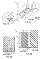
- FIG. 1A is a schematic perspective view of a thin-film magnetic head (simply referred to as a magnetic head 1, hereinafter) according to a first embodiment of the invention seen from a magnetic disk (not-shown magnetic recording medium).
- FIG. 1B is a partially expanded view of a partially expanded main portion of FIG. 1A.
- FIG. 2A is a sectional view of the magnetic head 1 cut along a surface extending in a track direction of a magnetic disk. Further, FIG. 2B is a partially expanded view of a partially expanded main portion of FIG. 2A.
- a coil is omitted to simplify the drawing.
- the track direction indicates a direction along a track concentrically formed in a magnetic disk (not shown), in other words, a direction orthogonal to the radial direction of the magnetic disk.
- a track width direction indicates the radial direction of the magnetic disk.
- the magnetic head 1 of the embodiment functions as a recording head for recording information in a magnetic disk (not shown) of a perpendicular magnetic recording system which has a double-layer film structure of soft magnetic layers.
- the magnetic head 1 of the embodiment is formed by depositing a plurality of materials on a flat substrate 2 made of an insulating material such as altec (Al 2 O 3 -TiC). According to the embodiment, a deposition direction of the materials coincides with the track direction.
- Articles deposited on the substrate 2 include a main pole 4 of a magnetic thin film made of, e.g., iron silicon nitrogen (FeSiN) or the like, two copper coils 6a, 6b, two return path yokes 8a, 8b made of magnetic thin films, e.g., cobalt zircon niobium (CoZrNb) or the like, and the like.
- the two coils 6a, 6b are disposed apart from the main pole 4 in a positional relation of sandwiching the main pole 4 in the deposition direction, and the two return path yokes 8a, 8b are disposed apart in a positional relation of sandwiching the coils.
- the distance between the main pole 4 and the two return path yokes 8a, 8b is set to 1000 to 5000 nm, and the distance is set to about 3600 nm according to the embodiment.
- the coils 6a, 6b are arranged between the main pole 4 and the two return path yokes 8a, 8b.
- an insulating layer 7 made of alumina (Al 2 O 3 ), silicon oxide (SiO 2 ) or the like is disposed to seal in the main pole 4 and the coils 6a, 6b.
- the deposits and the substrate 2 have an opposite surface 12 formed to be flush by polishing an end surface extending in a deposition direction.
- the opposite surface 12 of the magnetic head 1 extends roughly parallel to the deposition direction. Then, the magnetic head 1 is arranged in a posture which causes the opposite surface 12 to face the surface of a magnetic disk (not shown).
- An auxiliary yoke 10 made of a magnetic thin film such as iron silicon nitrogen (FeSiN) is disposed in the opposite surface 12.
- the auxiliary yoke 10 of the embodiment is disposed by etching the insulating layer 7, and its surface extends in the deposition direction to constitute the opposite surface 12 with an end surface of the substrate 2, a tip surface 4a of the main pole 4, and end surfaces of the return path yokes 8a, 8b.
- the auxiliary yoke 10 has a rectangular opening which surrounds the rectangular tip surface 4a (tip) of the main pole 4 exposed to the opposite surface 12 in noncontact.
- the rectangular opening has four opening end surfaces 10a equivalent to a thickness of the auxiliary yoke 10, and all the opening end surfaces 10a face the main pole 4 in noncontact.
- the auxiliary yoke 10 constitutes a magnetic circuit with the main pole 4, the return path yokes 8a, 8b, and the coils 6a, 6b.
- a gap between a side face 4b near the tip surface 4a of the main pole 4 and the opening end surface 10a of the auxiliary yoke 10 functions as a magnetic gap, and it is set to a predetermined separation length.
- the separation length is preferably set to 10 to 200 nm, and the separation length is set to 100 nm according to the embodiment.
- a rectangular frame-shaped magnetic gap will be set as an opening portion 20.
- the coils 6a, 6b are wound once to simplify the drawings. However, the two coils 6a, 6b are wound three times and interconnected at the centers.
- the main pole 4 is excited by applying currents reverse to each other to the coils 6a, 6b through a driving circuit (not shown), and a strong recording magnetic field is generated in the tip surface 4a of the main pole 4.
- a very hard protective film of a diamondlike carbon (DLC) or the like is formed to adhere to the opposite surface 12.
- DLC diamondlike carbon
- a gap between the side face 4b of the main pole 4 and the opening end surface 10a of the auxiliary yoke 10, i.e., a separation length of the opening portion 20, is constant over the entire circumference of the main pole 4.
- FIG. 3 shows a relationship between a magnetic field strength and a magnetic field gradient which are obtained from the magnetic field strength distribution in the track direction when the separation length of the magnetic head 1 of the aforementioned structure is varied.
- a magnetic field strength distribution having a peak magnetic field gradient in an area of a relatively high magnetic field strength is set, creating a problem of not always obtaining a high magnetic field gradient by a magnetic field strength necessary for recording.
- a magnetic field gradient can be increased by magnetic field strengths of a wide range.
- FIG. 4 shows a relationship between magnetic field strength and magnetic field gradient when the thickness of the auxiliary yoke 10 of the magnetic head 1 of the aforementioned structure is varied. It can be understood from the drawing that since a thicker auxiliary yoke 10 causes a conspicuous reduction in maximum magnetic field strength, the foregoing effects can be provided by making the auxiliary yoke 10 thinner than at least 200 nm.
- a separation length is 50 nm and a thickness of the auxiliary yoke 10 is 20 nm under the calculation conditions
- a reduction in the maximum magnetic field strength is limited to about 15% of that of the case of no auxiliary yoke (number of opposite surfaces is 0).
- number of opposite surfaces is 0
- FIG. 6 shows a relationship between a distance apart from the center of the main pole 4 in the track width direction and a magnetic field strength in its position when the separation length is a parameter. It can be understood that spread of magnetic field strength distribution is suppressed more as the separation length becomes smaller. That is, by reducing the separation length, it is possible to suppress the spread of the magnetic field strength distribution with respect to a track of the magnetic disk, to make a magnetic field sharp in the track width direction, and to increase a recording density.
- a sharp magnetic field can be simultaneously achieved in the track direction and the track width direction.
- the magnetic head 1 of the embodiment has a feature that a degree of freedom is large concerning the outer size and the positional relation of the auxiliary yoke 10 to the return path yokes 8a, 8b.
- the film thickness of the auxiliary yoke 10, and the size of the opening portion 20, i.e., the separation length, are important for generating a sharp magnetic field and obtaining a sufficient magnetic field strength.
- a shape may be contrived by using the fact that the sharpness of the magnetic field is influenced by the separation length.
- FIG. 8A shows the rectangular frame-shaped opening portion 20 which forms a fixed gap around the tip surface 4a of the main pole 4 as described above.
- FIG. 8B is a contour map of a strength distribution of a magnetic field applied to the magnetic disk when the opening portion 20 of such a shape is employed.
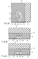
- FIG. 9A shows an opening portion 20' of a shape in which roughly circular openings are formed at four corners
- FIG. 9B is a contour map of a strength distribution of a magnetic field when the opening portion 20' is employed.
- the magnetic field strength distribution of the magnetic disk can be changed by changing the shape of the opening portion 20' as shown in FIG. 9A.
- the opening portion shape of the auxiliary yoke can be a circular arc of a polarity opposite to that of magnetization transfer, and a proper linear magnetization transfer shape can be realized.
- a layer of one return path yoke 8a is formed on the substrate 2, and the coil 6a, the main pole 4, the coil 6b, and the other return path yoke 8b are sequentially deposited through the insulating layer 7.
- a protective layer 9 is formed outside the return path yoke 8b when necessary. Then, the opposite surface 12 extending in the deposition direction of each layer is formed by polishing.
- a magnetic thin film is bonded to the polished opposite surface 12 to form the auxiliary yoke 10.
- a method of forming and bonding the auxiliary yoke 10 to the opposite surface 12 will be described.
- a photoresist 14 is patterned on the opposite surface 12, and a trench 16 is formed by ion beam etching or reactive ion etching to be similar in shape and thickness to the auxiliary yoke 10.
- a magnetic thin film is bonded and lifting-off is executed, whereby the magnetic thin film is buried in the trench 16 to form the auxiliary yoke 10.
- auxiliary yoke 10 By forming the auxiliary yoke 10 as in the case of the example, it is possible to highly accurately form the auxiliary yoke 10 while the length of the end surface 10a opposite to the main pole 4 (i.e., a thickness of the auxiliary yoke 10) is an order of nm. Thus, a sharp magnetic field strength applied to the magnetic disk can be achieved, and a magnetic field of a strength sufficient for recording can simultaneously be formed.
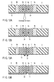
- a magnetic thin film 10' for the auxiliary yoke 10 is formed and bonded to the opposite surface 12.
- a photoresist 18 is patterned.
- this as a mask by ion beam etching or reactive ion etching, as shown in FIG. 11C, an opening portion 20 is formed in the magnetic thin film 10'.
- a magnetic thin film similar to that of the auxiliary yoke 10 is also formed in the tip surface 4a of the main pole 4. Accordingly, as compared to the first example, accuracy of the separation length can be increased. In other words, a gap between the main pole 4 and the auxiliary yoke 10 can be highly accurately formed depending on the shape of the resist 18.
- a magnetic thin film 10' for the auxiliary yoke 10 is deposited on the opposite surface 12. Then, as shown in FIG. 12B, an opening portion 20 is formed by using a converged ion beam etching device (not shown).
- a converged ion beam etching device not shown.
- effects similar to those of the second example can be provided without using a photoresist 18 similar to that of the second example.
- a photoresist 22 of a shape corresponding to the opening portion 20 is formed in the opposite surface 12 by using an electron beam exposure device (not shown). Then, as shown in FIG. 13B, a magnetic thin film 10' for the auxiliary yoke 10 is deposited from above the photoresist, and lifting-off is executed, whereby the auxiliary yoke 10 having the opening portion 20 is formed.
- effects similar to those of the second and third examples can be provided.
- the auxiliary yoke 10 is formed between the two return path yokes 8a, 8b in the first example (FIGS. 10A and 10B), and the auxiliary yoke 10 is formed on a full surface of the opposite surface 12 in the second to fourth examples.
- the outer size of the auxiliary yoke 10 is not limited to that of each of the examples.
- the auxiliary yoke 10 is formed by being buried in the insulating layer 7, no irregularities occur in the opposite surface 12 of the magnetic head 1.
- a step equal to a thickness of the auxiliary yoke 10 is formed with the opposite surface 12.
- a size and a position of the nonmagnetic material 24 can be determined to be optimal for the auxiliary yoke 10.
- the auxiliary yoke 10 made of the thin film is formed to adhere to the opposite surface 12 of the magnetic head 1, the auxiliary yoke 10 can be highly accurately and easily formed by setting its film thickness to, e.g., 200 nm or lower.
- the auxiliary yoke 10 and the tip of the main pole 4 can be simultaneously formed, it is possible to highly accurately set a separation length between the main pole 4 and the auxiliary yoke 10.
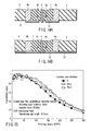
- FIG. 15 shows magnetic recording characteristics evaluated by combining the magnetic head 1 comprising the auxiliary yoke 10 manufactured according to the third example described above with reference to FIGS. 12A and 12B with a magnetic disk (not shown) having a double-layer film for perpendicular magnetic recording.
- a conventional magnetic head auxiliary yoke thickness 0
- higher recording resolution is realized for the magnetic head 1 of the invention which comprises the auxiliary yoke 10
- a sharp recording magnetic field is achieved in the track direction.
- FIGS. 16 and 17 Functional components similar to those of the first embodiment are denoted by similar reference numerals, and detailed description thereof will be omitted.
- the magnetic head 30 of this embodiment is characterized by depositing a plurality of thin films in a direction perpendicular to a surface 12 opposite to a magnetic disk (not shown) to be formed.
- the opposite surface 12 of the magnetic head 30 becomes a surface roughly parallel to a substrate 2.
- the magnetic head 30 is a so-called planar thin-film single pole magnetic head in which an auxiliary yoke 10 is further deposited on the opposite surface 12 of a main pole 4, a return path yoke 8, a coil 6 and an insulating layer 7 deposited on the substrate 2.
- the auxiliary yoke 10 comprises an opening portion 20 for forming a gap with the main pole 4, and its surface is made of a magnetic thin film to form the same plane with a tip surface 4a of the main pole 4.
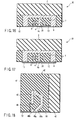
- a method of forming the auxiliary yoke 10 for example, there are a method of forming the auxiliary yoke 10 after a trench similar in shape to the auxiliary yoke 10 is formed in the opposite surface 12 as shown in FIG. 16, and a method of forming the auxiliary yoke 10 by depositing a magnetic thin film including an area of the tip surface 4a of the main pole 4 on the opposite surface 12 as shown in FIG. 17.
- the method of manufacturing the auxiliary yoke 10 is similar to that of the first embodiment, and thus detailed description thereof will be omitted.
- a nonmagnetic thin film is formed to remove a film thickness direction step formed by the auxiliary yoke 10, and to secure floating characteristics or abrasion characteristics of the magnetic head 30, or a protective film such as DLC (not shown) is formed.
- the embodiment effects similar to those of the first embodiment can be provided.
- the polishing step of the first embodiment before the formation of the auxiliary yoke is made unnecessary, and the auxiliary yoke 10 can be formed simultaneously in the deposition process.
- the number of steps in the manufacturing process can be reduced, and the embodiment is advantageous for miniaturization and weight-reduction.
- FIGS. 18 and 19 a magnetic head 40 according to a third embodiment of the invention will be described with reference to FIGS. 18 and 19.
- the first and second embodiments have been described by way of case in which the invention is applied to the recording magnetic head.
- a case in which the invention is applied to a reproducing magnetic head will be described.
- the magnetic head 40 has a structure in which an auxiliary yoke 50 is arranged in an opposite surface 52 of a magnet-resistive effect thin-film magnetic head of a conventional structure to guide a signal magnetic flux from a magnetic disk (not shown) through a magnetic yoke 48 to a (anisotropic, giant, and tunnel) magneto-resistance effect element 46.
- the magnetic head 40 is formed in a manner that a magnetic yoke 48 and a magneto-resistance effect element 46 are formed, and then a surface 52 opposite to a magnetic disk is set in a predetermined position of the magnetic yoke 48 by polishing. Subsequently, in the polished opposite surface 52, an auxiliary yoke 50 made of a magnetic thin film is formed to be flush with a tip surface of the magnetic yoke 48 through a gap with tips 48a, 48b of the magnetic yokes 48.
- auxiliary yoke 50 When the auxiliary yoke 50 is formed, there are a method of forming the auxiliary yoke 50 after a trench similar in shape to the auxiliary yoke 50 is formed in the opposite surface 52 as shown in FIG. 18, and a method of forming the auxiliary yoke 50 by forming a magnetic thin film including a tip surface area of the magnetic yoke 48 on the opposite surface 52 as shown in FIG. 19.
- description of a method of manufacturing the auxiliary yoke 50 will be omitted.
- a nonmagnetic thin film is formed to remove a film thickness direction step formed by the auxiliary yoke 50, and to secure floating characteristics or abrasion characteristics of a magnetic recording head, or a protective film such as a DLC is formed.
- a pole structure for realizing the sharp recording magnetic field concerning the recording magnetic heads 1, 30 of the foregoing first and second embodiments is also a structure for achieving a sharp reproducing sensitivity distribution by regarding the main pole 4 of the recording single pole head as a magnetic yoke 48 of a reproducing yoke type magneto-resistive effect head.
- the auxiliary yoke 50 present in the track width direction side face of the tip of the magnetic yoke 48 is useful as a magnetic shield for reducing side fade crosstalk.
- waveform distortion occurs in the case of applying the yoke type magneto-resistive effect head to perpendicular magnetic recording.
- the distortion can be reduced by drawing a signal magnetic flux only from the magnetic disk directly below the tip surface of the magnetic yoke 48 thereinto.
- the auxiliary yoke 50 present in the track direction is useful as a magnetic shield for reducing flowing-in of a magnetic flux from other than a portion directly below the recording medium. Accordingly, the waveform distortion is reduced to increase a recording density.
- the magnetic head 60 is manufactured by depositing a plurality of thin films in a direction perpendicular to a surface 61 opposite to a magnetic disk (not shown).
- the magnetic head 60 is manufactured by depositing a (anisotropic, giant, and tunnel) magneto-resistive effect element 63, magnetic yokes 64a, 64b, and an insulating layer 65 on a substrate 62, and forming an auxiliary yoke 66 made of a magnetic thin film to be flush with a tip surface of the magnetic yoke 64 through a gap with the magnetic yokes 64a, 64b in the surface 61 of the deposits opposite to the magnetic disk.
- a (anisotropic, giant, and tunnel) magneto-resistive effect element 63, magnetic yokes 64a, 64b, and an insulating layer 65 on a substrate 62, and forming an auxiliary yoke 66 made of a magnetic thin film to be flush with a tip surface of the magnetic yoke 64 through a gap with the magnetic yokes 64a, 64b in the surface 61 of the deposits opposite to the magnetic disk.
- a method of forming the auxiliary yoke 66 there are a method of forming the auxiliary yoke 66 after a trench similar in shape to the auxiliary yoke 66 is formed in the opposite surface 61 as shown in FIG. 20, and a method of forming the auxiliary yoke 66 by depositing a magnetic thin film including a tip surface area of the magnetic yoke 64 on the opposite surface 61 as shown in FIG. 21. Subsequently, as occasion demands, a nonmagnetic thin film is formed to remove a film thickness direction step formed by the auxiliary yoke 66, and to secure floating characteristics or abrasion characteristics of a magnetic head 60, or a protective film such as a DLC is formed.
- the embodiment is advantageous for miniaturization and weight-reduction.
- the magnetic head 70 has a structure in which the magnetic head 1 of the first embodiment and the magnetic head 40 of the third embodiment are formed on the same substrate 2.
- the magnetic head 70 is a recording/reproducing head for recording/reproducing information on/from a magnetic disk.
- the magnetic head 40 of the third embodiment is first manufactured on the substrate 2, and subsequently the magnetic head 1 of the first embodiment is manufactured thereon. Description of a specific method of manufacturing each of the magnetic heads 1, 40 will be omitted.
- auxiliary yokes 10, 50 of the two magnetic heads 1, 40 are simultaneously formed. That is, by polishing an opposite surface 12 after the recording magnetic head 1 is manufactured and depositing a magnetic thin film on the surface 12 to execute patterning, the auxiliary yokes 10, 50 of the recording magnetic head 1 and the reproducing magnetic head 40 are simultaneously formed together. Description of a method of manufacturing each of the auxiliary yokes 10, 50 will also be omitted.
- the auxiliary yoke 10 of the recording magnetic head 1 and the auxiliary yoke 50 of the reproducing magnetic head 40 can be simultaneously formed together to reduce the number of manufacturing steps. Moreover, according to the embodiment, it is possible to simultaneously provide a recording magnetic head capable of increasing a recording density in a magnetic disk and a reproducing magnetic head capable of reproducing data recorded at a high recording density.
- the magnetic head 80 has a planar structure in which the magnetic head 30 of the second embodiment and the magnetic head 60 of the fourth embodiment are formed on the same substrate 2. This magnetic head 80 is also a recording/reproducing head.
- the two magnetic heads 30, 60 are simultaneously manufactured in parallel.
- the magnetic head 80 can be formed by simultaneously forming auxiliary yokes 10, 66 together.
- the embodiment can provide effects similar to those of the fifth embodiment.
- the auxiliary yokes 10, 66 can be simultaneously formed in a deposition process of another layer in addition to nonnecessity of a polishing step before the formation of the auxiliary yokes, the number of steps can be further reduced compared with that of the fifth embodiment.
- the film thickness of the auxiliary yoke can easily and highly accurately set low, and thus a recording magnetic field can be made sharp without any conspicuous reductions thereof. As a result, it is possible to increase recording density by increases in linear recording density and track density.
- the invention when the invention is applied to the reproducing thin-film magnetic head, it is possible to increase a recording density by reductions in side face crosstalk and waveform distortion. Since the auxiliary yoke can be formed together with the recording single pole magnetic head, it is possible to easily realize a combination with the recording head.
Landscapes
- Engineering & Computer Science (AREA)
- Manufacturing & Machinery (AREA)
- Magnetic Heads (AREA)
Abstract
Description
Claims (19)
- A thin-film magnetic head characterized by comprising:a main pole which has a tip exposed to a surface opposite to a magnetic recording medium and which is made of a magnetic thin film extending in a direction apart from the opposite surface;a return path yoke which is disposed roughly in parallel with the main pole and which has a tip exposed to the opposite surface and which is made of a magnetic thin film extending in a direction apart from the opposite surface;a coil which forms a magnetic field in the tip of the main pole; andan auxiliary yoke made of a magnetic thin film which is formed in the opposite surface in noncontact with the tip of the main pole through a predetermined gap.
- The thin-film magnetic head according to claim 1, characterized in that the auxiliary yoke is formed to be flush with the tip of the main pole and the tip of the return path yoke in the opposite surface.
- The thin-film magnetic head according to claim 1, characterized in that a film thickness of the auxiliary yoke is 5 to 200 nm, and a gap between the main pole and the auxiliary yoke is 10 to 200 nm.
- The thin-film magnetic head according to claim 1 or 3, characterized in that the auxiliary yoke has an opening portion which exposes the tip of the main pole to the opposite surface in noncontact with the tip through the predetermined gap.
- The thin-film magnetic head according to claim 1 or 2, characterized by comprising a protective film which protects the opposite surface.
- The thin-film magnetic head according to claim 1, characterized in that the auxiliary yoke is deposited in the same direction as that for the main pole, the return path yoke and the coil.
- A thin-film magnetic head characterized by comprising:a magnetic yoke which has a tip exposed to a surface opposite to a magnetic recording medium;a magneto-resistive effect element which obtains a signal magnetic flux from the magnetic recording medium through the magnetic yoke; andan auxiliary yoke made of a magnetic thin film which is formed in the opposite surface in noncontact with the tip of the magnetic yoke through a predetermined gap.
- The thin-film magnetic head according to claim 7, characterized in that the auxiliary yoke is formed to be flush with the tip of the magnetic yoke in the opposite surface.
- The thin-film magnetic head according to claim 7 or 8, characterized by comprising a protective film which protects the opposite surface.
- A thin-film magnetic head characterized by forming the thin-film magnetic head of claim 1 and the thin-film magnetic head of claim 7 together on the same substrate.
- The thin-film magnetic head according to claim 10, characterized in that the auxiliary yoke of the thin-film magnetic head of claim 1 and the auxiliary yoke of the thin-film magnetic head of claim 7 are simultaneously disposed roughly parallel to the substrate.
- A method of manufacturing a thin-film magnetic head characterized by comprising:a deposition step of depositing a main pole made of a magnetic thin film, a return path yoke made of a magnetic thin film, and a coil made of a conductive thin film on a substrate through an insulating layer;a polishing step of polishing an end surface in a deposition direction of the articles deposited in the deposition step to form a surface opposite to a magnetic recording medium; andan auxiliary yoke formation step of forming, in the opposite surface, an auxiliary yoke made of a magnetic thin film which extends to be flush with the opposite surface in noncontact with the main pole through a predetermined gap.
- The method according to claim 12, characterized in that the auxiliary yoke formation step includes:a step of forming a magnetic thin film on the opposite surface formed in the polishing step; anda step of forming the gap in the magnetic thin film.
- The method according to claim 12 or 13, characterized in that the auxiliary yoke formation step includes a step of forming an opening portion which exposes the tip of the main pole to the opposite surface in noncontact with the tip through the predetermined gap.
- The method according to claim 12, characterized in that a film thickness of the auxiliary yoke is 5 to 200 nm, and a gap between the main pole and the auxiliary yoke is 10 to 200 nm.
- A method of manufacturing a thin-film magnetic head characterized by comprising:a deposition step of depositing a main pole, a return path yoke and a coil on a substrate through an insulating material; andan auxiliary yoke formation step of depositing and forming, in the same direction as that of the articles deposited in the deposition step, an auxiliary yoke made of a magnetic thin film which extends to be flush with an opposite surface in noncontact with the main pole through a predetermined gap in the opposite surface of one end of a deposition direction of the articles which faces a magnetic recording medium.
- The method according to claim 16, characterized in that the auxiliary yoke formation step includes:a step of depositing a magnetic thin film on the opposite surface; anda step of forming the gap in the magnetic thin film.
- The method according to claim 16 or 17, characterized in that the auxiliary yoke formation step includes a step of forming an opening portion which exposes the tip of the main pole to the opposite surface in noncontact with the tip through the predetermined gap.
- The method according to claim 16, characterized in that a film thickness of the auxiliary yoke is 5 to 200 nm, and a gap between the main pole and the auxiliary yoke is 10 to 200 nm.
Applications Claiming Priority (3)
| Application Number | Priority Date | Filing Date | Title |
|---|---|---|---|
| JP2002188505 | 2002-06-27 | ||
| JP2002188505A JP3806372B2 (en) | 2002-06-27 | 2002-06-27 | Thin-film magnetic head and manufacturing method thereof |
| PCT/JP2003/008218 WO2004003892A1 (en) | 2002-06-27 | 2003-06-27 | Thin film magnetic head and method of producing the head |
Publications (2)
| Publication Number | Publication Date |
|---|---|
| EP1533792A1 true EP1533792A1 (en) | 2005-05-25 |
| EP1533792A4 EP1533792A4 (en) | 2006-01-11 |
Family
ID=29996821
Family Applications (1)
| Application Number | Title | Priority Date | Filing Date |
|---|---|---|---|
| EP03736295A Withdrawn EP1533792A4 (en) | 2002-06-27 | 2003-06-27 | THIN FILM MAGNETIC HEAD AND METHOD FOR PRODUCING THE SAME |
Country Status (3)
| Country | Link |
|---|---|
| EP (1) | EP1533792A4 (en) |
| JP (1) | JP3806372B2 (en) |
| WO (1) | WO2004003892A1 (en) |
Families Citing this family (6)
| Publication number | Priority date | Publication date | Assignee | Title |
|---|---|---|---|---|
| US7322095B2 (en) * | 2004-04-21 | 2008-01-29 | Headway Technologies, Inc. | Process of manufacturing a four-sided shield structure for a perpendicular write head |
| US7289295B2 (en) * | 2004-05-12 | 2007-10-30 | Headway Technologies, Inc. | Return pole field reduction for perpendicular write head |
| JP4763264B2 (en) | 2004-10-25 | 2011-08-31 | ヒタチグローバルストレージテクノロジーズネザーランドビーブイ | Magnetic head for perpendicular recording |
| JP3992285B2 (en) * | 2004-12-16 | 2007-10-17 | 独立行政法人科学技術振興機構 | Thin-film magnetic head and manufacturing method thereof |
| WO2007074522A1 (en) * | 2005-12-27 | 2007-07-05 | Fujitsu Limited | Magnetic head and disc device |
| JP2012150863A (en) | 2011-01-18 | 2012-08-09 | Toshiba Corp | Recording head and disk drive with the same |
Family Cites Families (5)
| Publication number | Priority date | Publication date | Assignee | Title |
|---|---|---|---|---|
| JP2502490B2 (en) * | 1983-08-08 | 1996-05-29 | 日本電信電話株式会社 | Perpendicular magnetic recording head |
| JPS6448217A (en) * | 1987-08-19 | 1989-02-22 | Nippon Telegraph & Telephone | Floating type magnetic head |
| JPH04245009A (en) * | 1991-01-31 | 1992-09-01 | Victor Co Of Japan Ltd | Thin-film type vertical head |
| JPH06267036A (en) * | 1993-03-17 | 1994-09-22 | Matsushita Electric Ind Co Ltd | Thin film magnetic head |
| JPH07287817A (en) * | 1994-04-15 | 1995-10-31 | Citizen Watch Co Ltd | Magnetoresistive head |
-
2002
- 2002-06-27 JP JP2002188505A patent/JP3806372B2/en not_active Expired - Lifetime
-
2003
- 2003-06-27 WO PCT/JP2003/008218 patent/WO2004003892A1/en not_active Ceased
- 2003-06-27 EP EP03736295A patent/EP1533792A4/en not_active Withdrawn
Also Published As
| Publication number | Publication date |
|---|---|
| WO2004003892A1 (en) | 2004-01-08 |
| JP2004030838A (en) | 2004-01-29 |
| EP1533792A4 (en) | 2006-01-11 |
| JP3806372B2 (en) | 2006-08-09 |
Similar Documents
| Publication | Publication Date | Title |
|---|---|---|
| US20050111138A1 (en) | Thin-film magnetic head and its manufacturing method | |
| US8009386B2 (en) | Magnetic tape head with magnetic head layer formed on base substrate | |
| US6922316B2 (en) | Thin-film magnetic head and method of manufacturing same | |
| EP0881627A2 (en) | Thin film magnetic head | |
| US6636390B2 (en) | Magnetic head and magnetic recording and reproducing system | |
| US6198600B1 (en) | Thin film magnetic head and manufacturing method thereof | |
| US7180705B2 (en) | Thin film magnetic head capable of reducing expansion and bending of a recording pattern, method of manufacturing the same and magnetic recording apparatus | |
| US6728064B2 (en) | Thin-film magnetic head having two magnetic layers, one of which includes a pole portion layer and a yoke portion layer, and method of manufacturing same | |
| US7019943B2 (en) | Thin-film magnetic head with improved external magnetic field-blocking characteristics | |
| JP2002163809A (en) | Method of manufacturing magnetoresistive element and method of manufacturing magnetoresistive magnetic head | |
| US6984333B2 (en) | Thin film magnetic head, method of manufacturing the same and magnetic recording apparatus | |
| JPH10334410A (en) | Thin film magnetic head and method of manufacturing the same | |
| US6656538B2 (en) | Method of manufacturing magnetoresistive device, method of manufacturing thin film magnetic head, and method of forming thin film pattern | |
| US6850390B2 (en) | Thin-film magnetic head and method of manufacturing same | |
| JP3806372B2 (en) | Thin-film magnetic head and manufacturing method thereof | |
| JP2701796B2 (en) | Thin film magnetic head and method of manufacturing the same | |
| US7463448B2 (en) | Thin film magnetic head having upper and lower poles and a gap film within a trench | |
| EP1187104A2 (en) | A magnetic recording head, a magnetic reproducing head, a magnetic recording apparatus, and a magnetic reproducing apparatus | |
| JP2002100010A (en) | Yoke type reproducing magnetic head, method of manufacturing the same, and magnetic disk drive | |
| JP2005129219A (en) | Magnetic head, head gimbals assembly, hard disk device, and method for manufacturing magnetic head | |
| JP2002208114A (en) | Thin film magnetic head and method of manufacturing the same | |
| JP2003006811A (en) | Thin film magnetic head and method of manufacturing the same | |
| JP3474533B2 (en) | Thin film magnetic head and method of manufacturing the same | |
| US20020057525A1 (en) | Method of manufacturing a magnetic element | |
| CN101465125B (en) | Method for manufacturing magnetic head slider |
Legal Events
| Date | Code | Title | Description |
|---|---|---|---|
| PUAI | Public reference made under article 153(3) epc to a published international application that has entered the european phase |
Free format text: ORIGINAL CODE: 0009012 |
|
| 17P | Request for examination filed |
Effective date: 20050105 |
|
| AK | Designated contracting states |
Kind code of ref document: A1 Designated state(s): AT BE BG CH CY CZ DE DK EE ES FI FR GB GR HU IE IT LI LU MC NL PT RO SE SI SK TR |
|
| AX | Request for extension of the european patent |
Extension state: AL LT LV MK |
|
| DAX | Request for extension of the european patent (deleted) | ||
| RBV | Designated contracting states (corrected) |
Designated state(s): DE FR NL |
|
| A4 | Supplementary search report drawn up and despatched |
Effective date: 20051011 |
|
| RIC1 | Information provided on ipc code assigned before grant |
Ipc: 7G 11B 5/265 B Ipc: 7G 11B 5/39 B Ipc: 7G 11B 5/31 A |
|
| RA4 | Supplementary search report drawn up and despatched (corrected) |
Effective date: 20051011 |
|
| RA4 | Supplementary search report drawn up and despatched (corrected) |
Effective date: 20051130 |
|
| RA4 | Supplementary search report drawn up and despatched (corrected) |
Effective date: 20051011 |
|
| STAA | Information on the status of an ep patent application or granted ep patent |
Free format text: STATUS: THE APPLICATION IS DEEMED TO BE WITHDRAWN |
|
| 18D | Application deemed to be withdrawn |
Effective date: 20060613 |