EP1533522A2 - Problem determination device and control device for fluid device - Google Patents
Problem determination device and control device for fluid device Download PDFInfo
- Publication number
- EP1533522A2 EP1533522A2 EP04027422A EP04027422A EP1533522A2 EP 1533522 A2 EP1533522 A2 EP 1533522A2 EP 04027422 A EP04027422 A EP 04027422A EP 04027422 A EP04027422 A EP 04027422A EP 1533522 A2 EP1533522 A2 EP 1533522A2
- Authority
- EP
- European Patent Office
- Prior art keywords
- compressor
- determination device
- problem determination
- detecting
- contact
- Prior art date
- Legal status (The legal status is an assumption and is not a legal conclusion. Google has not performed a legal analysis and makes no representation as to the accuracy of the status listed.)
- Withdrawn
Links
Images

Classifications
-
- F—MECHANICAL ENGINEERING; LIGHTING; HEATING; WEAPONS; BLASTING
- F04—POSITIVE - DISPLACEMENT MACHINES FOR LIQUIDS; PUMPS FOR LIQUIDS OR ELASTIC FLUIDS
- F04B—POSITIVE-DISPLACEMENT MACHINES FOR LIQUIDS; PUMPS
- F04B51/00—Testing machines, pumps, or pumping installations
-
- F—MECHANICAL ENGINEERING; LIGHTING; HEATING; WEAPONS; BLASTING
- F04—POSITIVE - DISPLACEMENT MACHINES FOR LIQUIDS; PUMPS FOR LIQUIDS OR ELASTIC FLUIDS
- F04B—POSITIVE-DISPLACEMENT MACHINES FOR LIQUIDS; PUMPS
- F04B27/00—Multi-cylinder pumps specially adapted for elastic fluids and characterised by number or arrangement of cylinders
- F04B27/08—Multi-cylinder pumps specially adapted for elastic fluids and characterised by number or arrangement of cylinders having cylinders coaxial with, or parallel or inclined to, main shaft axis
- F04B27/10—Multi-cylinder pumps specially adapted for elastic fluids and characterised by number or arrangement of cylinders having cylinders coaxial with, or parallel or inclined to, main shaft axis having stationary cylinders
- F04B27/1036—Component parts, details, e.g. sealings, lubrication
-
- F—MECHANICAL ENGINEERING; LIGHTING; HEATING; WEAPONS; BLASTING
- F04—POSITIVE - DISPLACEMENT MACHINES FOR LIQUIDS; PUMPS FOR LIQUIDS OR ELASTIC FLUIDS
- F04B—POSITIVE-DISPLACEMENT MACHINES FOR LIQUIDS; PUMPS
- F04B2205/00—Fluid parameters
- F04B2205/50—Presence of foreign matter in the fluid
- F04B2205/501—Presence of foreign matter in the fluid of solid particles
Definitions
- the present invention relates to problem determination devices for determining whether or not a fluid device has a problem and control devices including such problem determination devices.
- a refrigerant compressor provided in a refrigerant circuit of a vehicle air conditioner includes a control device that determines whether or not the compressor has a problem such as deadlock (seizure).
- the control device controls the compressor when it is determined that the compressor has a problem.
- the control device is provided with a rotational speed sensor, or a lock sensor, for detecting the rotational speed of the compressor (the drive shaft of the compressor). If the difference between the rotational speed of the compressor, which is detected by the rotational speed sensor, and the speed of the engine, the drive source of the compressor, is equal to or larger than a predetermined value, the control device determines that the compressor has a problem such as deadlock. The control device then deactivates an electromagnetic clutch provided in a power transmitting line between the engine and the compressor. In this manner, the engine is prevented from being affected by the compressor problem.
- the control device determines whether or not the compressor has a problem in correspondence with the rotational speed of the compressor. However, if a problem is presented by the rotational speed of the compressor, it is indicated that the compressor is already in complete deadlock or a state immediately before complete deadlock. In other words, at this stage, the compressor problem is relatively severe. Therefore, the control device must shutter the power transmission between the engine and the compressor such that the engine is prevented from being affected by the compressor problem.
- compressors are clutchless.
- This type of compressor does not have an externally controllable clutch mechanism such as an electromagnetic clutch, which is disposed in a power transmitting line between an engine and a compressor. The drive shaft of the compressor is thus maintained in a driven state as long as the engine is operating. Accordingly, the conventional control device cannot be applied to the clutchless compressors.
- a torque limiter is provided in the power transmitting line between the engine and the compressor.
- the torque limiter stops excessive torque from being transmitted to the engine when the compressor is in deadlock. More specifically, for example, a certain type of torque limiters operates to rupture a portion of a power transmitting member by means of the excessive torque.
- the torque limiter must block the torque transmission immediately after the torque of the compressor exceeds the limit torque. Meanwhile, the torque limiter must reliably permit the torque transmission as long as the torque of the compressor remains smaller than the limit torque, even in a range close to the torque limit. The limit torque thus must be set in a precise manner, and such setting is complicated.
- the invention provides a problem determination device for a fluid device.
- the problem determination device includes an object sensor for detecting an undesirable object in the fluid device and a determining section.
- the object sensor includes a detecting portion provided in the fluid device.
- the determining section determines that the fluid device has a problem when the object sensor detects an undesirable object.
- the invention also provides a control device.
- the control device includes the above problem determination device and a displacement control section.
- the fluid device is a variable displacement compressor.
- the displacement control section decreases the displacement of the compressor when the determining section determines that the compressor has a problem.
- a first embodiment of the present invention or a control device for a piston type variable displacement compressor forming a refrigerant circuit of a vehicle air conditioner, will hereafter be described.
- piston type variable displacement compressor (hereinafter referred to simply as "compressor"), which is a fluid device, will be explained.
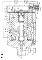
- Fig. 1 is a longitudinal cross-sectional view showing the compressor.
- the left corresponds to the front of the compressor, and the right corresponds to the rear of the compressor.
- the compressor includes a housing assembly formed by a cylinder block 11, a front housing member 12, and a rear housing member 14, each of which serves as a housing forming member.
- the front housing member 12 is connected to a front end of the cylinder block 11.
- the rear housing member 14 is connected to a rear end of the cylinder block 11 through a valve plate assembly 13.
- the cylinder block 11, the front housing member 12, and the rear housing member 14 are securely fastened together by means of a plurality of through bolts 15 (only one is shown in the drawing).
- a crank chamber 16 serving as a control chamber is defined by the cylinder block 11 and the front housing member 12.
- a portion of each of the through bolts 15 is exposed in the crank chamber 16 such that the exposed portions of the through bolts 15 are arranged along the circumference of the crank chamber 16.
- a drive shaft 17 is rotationally supported by the cylinder block 11 and the front housing member 12 such that the drive shaft 17 extends through the crank chamber 16.
- An engine E the drive source of the vehicle, is operationally connected to the drive shaft 17 through a clutchless type (constant operating type) power transmitting mechanism PT. That is, as long as the engine E is operating, the drive shaft 17 is constantly rotated by the power transmitted from the engine E.
- a rotor 18 is secured to the drive shaft 17 such that the rotor 18 rotates integrally with the drive shaft 17.
- the crank chamber 16 further accommodates a substantially disk-like swash plate 19 serving as a cam plate, which is formed of iron-based metal material.
- the drive shaft 17 is passed through the center of the swash plate 19.
- the drive shaft 17 thus supports the swash plate 19 to allow the swash plate 19 to rotate integrally with the drive shaft 17 and incline with respect to the drive shaft 17.
- a hinge mechanism 20 is disposed between the rotor 18 and the swash plate 19.
- the hinge mechanism 20 includes two rotor projections 20a (the one that is on this side of the top surface of the sheet of Fig. 1 is not shown) projecting from a rear side of the rotor 18 and a swash plate projection 20b projecting from a front side of the swash plate 19 toward the rotor 18.
- the distal end of the swash plate projection 20b is arranged between the rotor projections 20a. This structure enables the rotor projections 20a and the swash plate projection 20b to transmit the rotational force of the rotor 18 to the swash plate 19.
- a cam section 21 is formed at the proximal end of each of the rotor projections 20a.
- a cam surface 21a is formed at a rear side of the cam section 21 facing the swash plate 19.
- the distal end of the swash plate projection 20b is in contact with the cam surface 21a of the cam section 21 in a manner slidable along the cam surface 21a.
- the hinge mechanism 20 thus guides the swash plate 19 to incline with respect to the drive shaft 17 by means of the distal end of the swash plate projection 20b that slides along the cam surface 21a toward and away from the drive shaft 17.
- a plurality of cylinder bores 22 extend through the cylinder block 11 at constant angular intervals about the axis L of the drive shaft 17, in a frontward-rearward direction of the compressor (in a left-right direction as viewed in Fig. 1).
- a single headed piston 23 is received in each of the cylinder bores 22 and is allowed to reciprocate in the frontward-rearward direction.
- a rear opening of each cylinder bore 22 is closed by a front side of the valve plate assembly 13.
- a front opening of the cylinder bore 22 is closed by the associated piston 23.
- a compression chamber 24 is defined in each cylinder bore 22 such that the volume of the compression chamber 24 is changed in correspondence with the movement of the associated piston 23.
- Each of the pistons 23 is connected to an outer circumferential portion of the swash plate 19 through a pair of shoes 25 formed of iron-based metal material. Accordingly, when the swash plate 19 rotates integrally with the drive shaft 17 and inclines along the axis L of the drive shaft 17, the pistons 23 are permitted to reciprocate linearly in the frontward-rearward direction of the compressor.
- a suction chamber 26, or a suction pressure zone, and a discharge chamber 27, or a discharge pressure zone, are defined in the housing assembly of the compressor by the valve plate assembly 13 and the rear housing member 14.
- the valve plate assembly 13 has a plurality of suction ports 28 and a plurality of suction valve flaps 29. Each of the suction ports 28 and the associated one of the suction valve flaps 29 are located between the corresponding one of the compression chambers 24 and the suction chamber 26.
- the valve plate assembly 13 has a plurality of discharge ports 30 and a plurality of discharge valve flaps 31. Each of the discharge ports 30 and the associated one of the discharge valve flaps 31 are located between the corresponding one of the compression chambers 24 and the discharge chamber 27.
- refrigerant gas is drawn from the suction chamber 26 to each of the compression chambers 24 through the corresponding suction port 28 opened by the associated suction valve flap 29, when the associated piston 23 moves from the top dead center to the bottom dead center.
- the refrigerant gas is thus compressed to a predetermined pressure when the piston 23 returns from the bottom dead center to the top dead center.
- the gas is then discharged to the discharge chamber 27 through the corresponding discharge port 30 opened by the associated discharge valve flap 31.
- a bleed passage 32, a supply passage 33, and a control valve 34 are formed in the housing assembly of the compressor.
- the bleed passage 32 connects the crank chamber 16 to the suction chamber 26.
- the supply passage 33 connects the discharge chamber 27 to the crank chamber 16.
- the control valve 34 is provided in the supply passage 33.
- the control valve 34 includes a valve housing 35 in which a valve chamber 38 and a valve hole 39 are defined.
- the valve chamber 38 and the valve hole 39 define a portion of the supply passage 33 in the control valve 34.
- the valve chamber 38 accommodates a valve body 41 and a closing spring 42.
- the valve body 41 adjusts the opening area of the valve hole 39.
- the closing spring 42 urges the valve body 41 in a direction closing the valve hole 39.
- An electromagnetic actuator 36 is connected to the valve housing 35 and includes a fixed iron core 43, a movable iron core 44, a coil 45, and an opening spring 46.
- the coil 45 is wound around the fixed iron core 43 and the movable iron core 44.
- the opening spring 46 urges the movable iron core 44 separately from the fixed iron core 43.
- the urging force of the opening spring 46 is transmitted to the valve body 41 through the movable iron core 44 and a rod 47 connecting the movable iron core 44 to the valve body 41.
- the valve body 41 thus receives the urging force of the opening spring 46 as force acting to open the valve hole 39.
- the urging force of the opening spring 46 is much larger than that of the closing spring 42.
- the coil 45 of the electromagnetic actuator 36 is supplied with a drive current (for example, a DC current) from an air conditioner ECU 48 through a valve driver 49 in correspondence with air conditioning load.
- a drive current for example, a DC current
- the valve body 41 is positioned at a position at which the force of the opening spring 46 is equilibrated with the force of the closing spring 42 acting against the force of the opening spring 46, thus changing the opening area of the valve hole 39, i.e., the opening size of the control valve 34.
- the opening size of the control valve 34 is adjusted by varying the amount of the drive current supply from the valve driver 49 to the coil 45.
- the opening size of the control valve 34 Through adjustment of the opening size of the control valve 34, the balance between the amount of the relatively high pressure gas supplied to the crank chamber 16 through the supply passage 33 and the amount of the gas escaped from the crank chamber 16 through the bleed passage 32 is controlled, such that the pressure in the crank chamber 16 is adjusted. In this manner, the difference between the pressure in the crank chamber 16 and the pressure in each of the compression chambers 24, which is brought about by the corresponding piston 23, is changed. This changes the inclining angle of the swash plate 19, thus adjusting the stroke of each piston 23, or the displacement of the compressor.
- a problem determination device for determining whether or not the compressor has a problem as well as a control device including the problem determination device, will now be explained.
- the control device (the problem determination device) is formed by the air conditioner ECU 48, which is a computer-like electronic control unit, and an object sensor 50 connected to the ECU 48.
- the object sensor 50 includes a detecting portion 51 provided in the crank chamber 16 of the compressor for detecting'an undesirable object in the crank chamber 16. If the object sensor 50 detects such object, the ECU 48 determines that the compressor has a problem.
- Fig. 2 is a diagram showing a detecting circuit (an electric circuit) of the object sensor 50.
- the detecting portion 51 of the object sensor 50 includes an insulating substrate 52, a first contact 53, and a second contact 54. More specifically, the first and second contacts 53, 54 are printed on the substrate 52.
- the contacts 53, 54 are each formed in a linear shape on the substrate 52 and extend parallel with each other, as spaced from each other at a predetermined interval.
- An anode of a DC power supply 55 is connected to the first contact 53, and a cathode of the DC power supply 55 is connected to the second contact 54 through a resistor 56.
- the DC power supply 55 is formed by, for example, a battery for driving the control valve 34 or an electric system of the engine E.
- An output portion 57 is connected to the resistor 56 in parallel. If the detecting circuit of the object sensor 50 is closed and voltage is applied to the resistor 56, the output portion 57 sends a problem detecting signal to the ECU 48.
- the output portion 57 and the resistor 56 are accommodated in a case (not shown) such that the output portion 57 and the resistor 56 are not exposed in the crank chamber 16.
- the case is formed integrally with the detecting portion 51 (the substrate 52).
- the output portion 57 and the resistor 56 are thus secured to the front housing member 12 by means of the case.
- the output portion 57 and the resistor 56 may be secured directly to the substrate 52 or integrated in an I/O of the ECU 48.
- the compressor when the compressor is operated in a relatively high load state such as an operational state corresponding to relatively high displacement, the compression load acting on the swash plate 19 through the pistons 23 and the shoes 25 becomes relatively high. In this state, lubrication may become insufficient between the swash plate 19 and the shoes 25. If the swash plate 19 and the shoes 25 are held in this insufficiently lubricated state for a relatively long time, a portion of the sliding surface(s) of the swash plate 19 (and the shoes 25) may exfoliate from the original surface(s), such that the separated portion falls in the crank chamber 16 as an undesirable object. As the rotor 18 and the swash plate 19 rotate and stir the atmosphere in the crank chamber 16, the object moves freely in the crank chamber 16.
- a relatively high load state such as an operational state corresponding to relatively high displacement
- the object which is conductive
- the first and second contacts 53, 54 are bridged to each other such that the contacts 53, 54 are connected to each other.
- the detecting circuit of the object sensor 50 is thus electrically closed, and the output portion 57 of the object sensor 50 sends the problem detecting signal to the ECU 48.
- the ECU 48 determines that the compressor has a problem.
- the determining process corresponds to a procedure executed by a determining section of the problem determination device.
- the ECU 48 instructs the valve driver 49 to suspend the drive current supply to the control valve 34, regardless of how great the air conditioning load is. If the drive current supply to the control valve 34 is stopped, the control valve 34 becomes fully open and the displacement of the compressor is minimized.
- This process corresponds to a procedure executed by a displacement control section of the control device. More specifically, if the displacement of the compressor is minimized, the compression load acting on the swash plate 19 through the pistons 23 and the shoes 25 is decreased, thus suppressing complete deadlock of the compressor. In other words, the compressor problem is prevented from becoming relatively severe.
- a problem indicating device for example, a warning lamp
- the ECU 48 operates the problem indicating device to indicate that the compressor has a problem and thus requires a checkup of the air conditioner.
- the illustrated embodiment has the following advantages.
- the power transmitting mechanism PT of the illustrated embodiment does not necessarily have to include the torque limiter, which is generally installed in a clutchless compressor, making it unnecessary to perform the complicated setting of the limit torque.
- the compressor problem is prevented from becoming relatively severe, excessive production of undesirable objects does not occur in the compressor. This prevents a failure from being caused in any device of an external circuit due to an undesirable object entering the external circuit from the compressor.
- the compressor problem is stopped at a relatively early stage, the origin of the undesirable object or a cause of the problem may be identified easily when the compressor is disassembled for maintenance or the like. This leads to improvement of the compressor.
- the first contact 53 of the object sensor 50 includes a plurality of (five, in this embodiment) linear portions 53a and the second contact 54 includes a plurality of (five, in this embodiment) linear portions 54a.
- the linear portions 53a, 54a are aligned parallel with one another and spaced from adjacent ones at constant intervals.
- the linear portions 53a of the first contact 53 and the linear portions 54a of the second contact 54 are arranged on the substrate 52 in an alternating manner.
- the contacts 53, 54 thus cover a relatively wide range, making it possible to detect an object at a further early stage of the compressor problem.
- the substrate 52 of the detecting portion 51 of the object sensor 50 has a cylindrical shape.
- the through bolt 15 is passed through the substrate 52, thus supporting the detecting portion 51 in the crank chamber 16.
- the detecting portion 51 of the third embodiment is configured identical to that of the second embodiment. That is, the first and second contacts 53, 54 of the third embodiment include a plurality of linear portions 53a, 54a.
- the through bolt 15 commonly for fastening the housing forming members together and supporting the detecting portion 51 in the housing assembly of the compressor, the number of components of the control device can be reduced.
- the substrate 52 through which the through bolt 15 is passed has a cylindrical shape.
- the space for the detecting portion 51 of the object sensor 50 is relatively small.
- the substrate 52 may be formed in a cylindrical shape originally, the substrate 52 may be formed by a flexible sheet and wound around the through bolt 15 for securing the substrate 52 to the through bolt 15. If the substrate 52 is shaped cylindrical originally, the shape of the substrate 52 is maintained in a stable state such that the substrate 52 is relatively easy to handle when securing the substrate 52 to the through bolt 15. If the substrate 52 is formed by the flexible sheet, the substrate 52, or the detecting portion 51, may become relatively thin, further saving the space for the detecting portion 51.
- the control device (the problem determination device) is configured by electrically connecting the object sensor 50, or the detecting portion 51, directly to the coil 45 of the control valve 34. Therefore, the air conditioner ECU 48 is not involved in the problem detection for the compressor or the compressor controlling in correspondence with the problem detection. More specifically, the first contact 53 of the detecting portion 51 is connected to a cable 60 connecting the valve driver 49 to the control valve 34 (the coil 45). The second contact 54 of the detecting portion 51 is connected to a different cable 62 connecting the valve driver 49 to the control valve 34 (the coil 45) through a resistor 61. The resistance value of the resistor 61 is sufficiently smaller than that of the coil 45.
- the resistance value of the resistor 61 is set such that the drive current supplied to the coil 45 of the control valve 34 is substantially nullified if the first and second contacts 53, 54 are bridged to each other by an undesirable object (for example, if the resistance value of the coil 45 is 10 Q, the resistance value of the resistor 61 is set as 1 Q). Accordingly, if the object sensor 50 detects an object, the control valve 34 becomes fully open, such that the compressor displacement is minimized.
- the detecting portion 51 of the object sensor 50 is electrically connected directly to the control valve 34 such that the amount of the drive current supplied from the valve driver 49 to the control valve 34 is decreased if an object is detected by the object sensor 50.
- This structure corresponds to the determining section of the problem determination device and the displacement control section of the control device. As a result, if it is determined that the compressor has a problem, the compressor displacement is minimized autonomously without depending on an external determination or control means such as the air conditioner ECU 48.
- the first contact 53 of the object sensor 50 includes a plurality of (three, in this embodiment) linear portions 53a and the second contact 54 includes a plurality of (three, in this embodiment) linear portions 54a.
- the linear portions 53a of the first contact 53 and the linear portions 54a of the second contact 54 are arranged on the substrate 52 in an alternating manner.
- a plurality of resistors 65 having equal resistance values are connected to the corresponding ones of the linear portions 54a of the second contact 54.
- the resistors 65 are connected to the cathode of the DC power supply 55 through a common output portion 66. That is, the resistors 65 are arranged in parallel. If the detecting circuit of the object sensor 50 is closed and a current flows through the output portion 66, the output portion 66 sends a signal corresponding to the current to the air conditioner ECU 48.
- the amount of the current flowing through the output portion 66 is varied depending on the number of the resistors 65 through which the current flows.
- the signal sent from the output portion 66 to the ECU 48 is thus changed in accordance with the amount of the current flowing through the output portion 66. If the signal received by the ECU 48 indicates that the current flows through two or more of the resistors 65, the ECU 48 determines that the compressor has a problem and minimizes the compressor displacement, thus avoiding an excessively sensitive detection.
- the compressor controlling when the ECU 48 determines that the compressor has a problem is not restricted to the above-described manner. For example, if the received signal indicates that the current flows through two of the resistors 65, the ECU 48 may reduce the drive current instruction to the valve driver 49 in correspondence with the air conditioning load by a predetermined amount, such that the compressor displacement becomes relatively small (not minimum). However, if the signal indicates that the current flows through three of the resistors 65, the ECU 48 may operate to minimize the compressor displacement. In other words, the ECU 48 may decrease the compressor displacement in a stepped manner for suppressing a quick minimization of the compressor displacement, or a sudden stop of the air conditioner, which is uncomfortable for vehicle users.
- the object sensor 50 includes the single detecting portion 51.
- the object sensor 50 may include a plurality of detecting portions 51 that are deployed at different positions in the crank chamber 16. This arrangement covers a relatively wide range in the crank chamber 16, making it possible to detect an undesirable object at a further early stage of a compressor problem.
- each of the detecting portions 51 may have a separate resistor 56 and a separate output portion 57.
- the detecting portions 51 may have a common resistor 56 and a common output portion 57. If the resistors 56 and the output portions 57 are provided separately for the corresponding ones of the detecting portions 51, the air conditioner ECU 48 determines that the compressor has a problem when receiving an object detecting signal from at least one of the output portions 57. However, the ECU 48 may be changed to determine that the compressor has a problem only when two or more of the output portions 57 send detecting signals to the ECU 48. An excessive sensitivity of the problem detection is thus avoided.
- the object sensor 50 may include a magnet portion disposed in the crank chamber 16 for attracting an undesirable object to the detecting portion 51.
- the substrate 52 of the detecting portion 51 may be formed by a non-conductive magnet.
- a magnet may be secured to the substrate 52 at a position between the first and second contacts 53, 54. In this manner, the object may be detected at a relatively early stage of a compressor problem. Further, since the magnet securely holds the object, the object is prevented from being separated from the detecting portion 51 and thus causing a problem at a separate position in the compressor.
- the detecting portion 51 of the object sensor 50 is provided in the crank chamber 16 of the compressor.
- the detecting portion 51 of the object sensor 50 may be deployed at a different location than the crank chamber 16, or, for example, in the suction chamber 26 or the discharge chamber 27.
- the ECU 48 adjusts (decreases) the compressor displacement based on the determination that the compressor has a problem.
- the ECU 48 may simply operate the problem indicating device to indicate that the compressor has a problem, without executing the compressor controlling corresponding to the problem detection.
- the second contact 54 of the detecting portion 51 of the object sensor 50 and the cathode of the DC power supply 55 may be connected to each other as grounded to the housing assembly of the compressor or the vehicle body.
- the present invention is not restricted to the application to the clutchless type compressor.
- the present invention may be applied to a compressor having a clutch including an externally controllable clutch mechanism such as an electromagnetic clutch, serving as the power transmitting mechanism PT.
- an externally controllable clutch mechanism such as an electromagnetic clutch
- the compressor displacement may be reduced as in the illustrated embodiments.
- the clutch mechanism may be deactivated.
- the present invention may be applied to different types of piston type compressors other than the swash plate type, including a wobble type and a wave cam type of compressors.
- the present invention may be applied to different fluid devices other than the refrigerant compressors, including hydraulic pumps and air compressors.
- a problem determination device for a fluid device includes an object sensor for detecting an undesirable object in the fluid device and a determining section.
- the object sensor includes a detecting portion provided in the fluid device.
- the determining section determines that the fluid device has a problem when the object sensor detects an undesirable object.
- the problem determination device is capable of accurately determining that the fluid device has a problem at a relatively early stage of the problem.
Landscapes
- Engineering & Computer Science (AREA)
- Mechanical Engineering (AREA)
- General Engineering & Computer Science (AREA)
- Compressors, Vaccum Pumps And Other Relevant Systems (AREA)
- Control Of Positive-Displacement Pumps (AREA)
Abstract
A problem determination device for a fluid device
includes an object sensor for detecting an undesirable object
in the fluid device and a determining section. The object
sensor includes a detecting portion provided in the fluid
device. The determining section determines that the fluid
device has a problem when the object sensor detects an
undesirable object. The problem determination device is
capable of accurately determining that the fluid device has a
problem at a relatively early stage of the problem.
Description
- The present invention relates to problem determination devices for determining whether or not a fluid device has a problem and control devices including such problem determination devices.
- For example, as described in Japanese Examined Utility Model Publication No. 4-50465, a refrigerant compressor provided in a refrigerant circuit of a vehicle air conditioner includes a control device that determines whether or not the compressor has a problem such as deadlock (seizure). The control device controls the compressor when it is determined that the compressor has a problem.
- More specifically, in order to determine whether or not the compressor has a problem, the control device is provided with a rotational speed sensor, or a lock sensor, for detecting the rotational speed of the compressor (the drive shaft of the compressor). If the difference between the rotational speed of the compressor, which is detected by the rotational speed sensor, and the speed of the engine, the drive source of the compressor, is equal to or larger than a predetermined value, the control device determines that the compressor has a problem such as deadlock. The control device then deactivates an electromagnetic clutch provided in a power transmitting line between the engine and the compressor. In this manner, the engine is prevented from being affected by the compressor problem.
- As has been described, the control device determines whether or not the compressor has a problem in correspondence with the rotational speed of the compressor. However, if a problem is presented by the rotational speed of the compressor, it is indicated that the compressor is already in complete deadlock or a state immediately before complete deadlock. In other words, at this stage, the compressor problem is relatively severe. Therefore, the control device must shutter the power transmission between the engine and the compressor such that the engine is prevented from being affected by the compressor problem.
- Further, some compressors are clutchless. This type of compressor does not have an externally controllable clutch mechanism such as an electromagnetic clutch, which is disposed in a power transmitting line between an engine and a compressor. The drive shaft of the compressor is thus maintained in a driven state as long as the engine is operating. Accordingly, the conventional control device cannot be applied to the clutchless compressors.
- Instead, in the clutchless compressors, a torque limiter is provided in the power transmitting line between the engine and the compressor. The torque limiter stops excessive torque from being transmitted to the engine when the compressor is in deadlock. More specifically, for example, a certain type of torque limiters operates to rupture a portion of a power transmitting member by means of the excessive torque.
- However, it is difficult to preferably set a limit torque for the torque limiters, which raises the cost needed for the compressor. In other words, the torque limiter must block the torque transmission immediately after the torque of the compressor exceeds the limit torque. Meanwhile, the torque limiter must reliably permit the torque transmission as long as the torque of the compressor remains smaller than the limit torque, even in a range close to the torque limit. The limit torque thus must be set in a precise manner, and such setting is complicated.
- Accordingly, it is an objective of the present invention to provide a problem determination device for a fluid device capable of accurately determining that the fluid device has a problem at a relatively early stage of the problem and a control device including this problem determination device.
- To achieve the foregoing and other objectives and in accordance with the purpose of the present invention, the invention provides a problem determination device for a fluid device. The problem determination device includes an object sensor for detecting an undesirable object in the fluid device and a determining section. The object sensor includes a detecting portion provided in the fluid device. The determining section determines that the fluid device has a problem when the object sensor detects an undesirable object.
- The invention also provides a control device. The control device includes the above problem determination device and a displacement control section. The fluid device is a variable displacement compressor. The displacement control section decreases the displacement of the compressor when the determining section determines that the compressor has a problem.
- Other aspects and advantages of the invention will become apparent from the following description, taken in conjunction with the accompanying drawings, illustrating by way of example the principles of the invention.
- The invention, together with objects and advantages thereof, may best be understood by reference to the following description of the presently preferred embodiments together with the accompanying drawings in which:
- Fig. 1 is a longitudinal cross-sectional view illustrating a piston type variable displacement compressor according to a first embodiment of the present invention;
- Fig. 2 is a diagram showing a detecting circuit of an object sensor of the first embodiment;
- Fig. 3 is an enlarged view showing a detecting portion of an object sensor of a second embodiment;
- Fig. 4 is a view showing the arrangement of a detecting portion of an object sensor of a third embodiment;
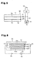
- Fig. 5 is a diagram showing a detecting circuit of an object sensor of a fourth embodiment; and
- Fig. 6 is a diagram showing a detecting circuit of an object sensor of a fifth embodiment.
-
- A first embodiment of the present invention, or a control device for a piston type variable displacement compressor forming a refrigerant circuit of a vehicle air conditioner, will hereafter be described.
- First, the piston type variable displacement compressor (hereinafter referred to simply as "compressor"), which is a fluid device, will be explained.
- Fig. 1 is a longitudinal cross-sectional view showing the compressor. In Fig. 1, the left corresponds to the front of the compressor, and the right corresponds to the rear of the compressor. As illustrated in Fig. 1, the compressor includes a housing assembly formed by a
cylinder block 11, afront housing member 12, and arear housing member 14, each of which serves as a housing forming member. Thefront housing member 12 is connected to a front end of thecylinder block 11. Therear housing member 14 is connected to a rear end of thecylinder block 11 through avalve plate assembly 13. Thecylinder block 11, thefront housing member 12, and therear housing member 14 are securely fastened together by means of a plurality of through bolts 15 (only one is shown in the drawing). - In the housing assembly of the compressor, a
crank chamber 16 serving as a control chamber is defined by thecylinder block 11 and thefront housing member 12. A portion of each of thethrough bolts 15 is exposed in thecrank chamber 16 such that the exposed portions of the throughbolts 15 are arranged along the circumference of thecrank chamber 16. Adrive shaft 17 is rotationally supported by thecylinder block 11 and thefront housing member 12 such that thedrive shaft 17 extends through thecrank chamber 16. An engine E, the drive source of the vehicle, is operationally connected to thedrive shaft 17 through a clutchless type (constant operating type) power transmitting mechanism PT. That is, as long as the engine E is operating, thedrive shaft 17 is constantly rotated by the power transmitted from the engine E. - In the
crank chamber 16, arotor 18 is secured to thedrive shaft 17 such that therotor 18 rotates integrally with thedrive shaft 17. Thecrank chamber 16 further accommodates a substantially disk-like swash plate 19 serving as a cam plate, which is formed of iron-based metal material. Thedrive shaft 17 is passed through the center of theswash plate 19. Thedrive shaft 17 thus supports theswash plate 19 to allow theswash plate 19 to rotate integrally with thedrive shaft 17 and incline with respect to thedrive shaft 17. Ahinge mechanism 20 is disposed between therotor 18 and theswash plate 19. - The
hinge mechanism 20 includes two rotor projections 20a (the one that is on this side of the top surface of the sheet of Fig. 1 is not shown) projecting from a rear side of therotor 18 and aswash plate projection 20b projecting from a front side of theswash plate 19 toward therotor 18. The distal end of theswash plate projection 20b is arranged between the rotor projections 20a. This structure enables the rotor projections 20a and theswash plate projection 20b to transmit the rotational force of therotor 18 to theswash plate 19. - A
cam section 21 is formed at the proximal end of each of the rotor projections 20a. A cam surface 21a is formed at a rear side of thecam section 21 facing theswash plate 19. The distal end of theswash plate projection 20b is in contact with the cam surface 21a of thecam section 21 in a manner slidable along the cam surface 21a. Thehinge mechanism 20 thus guides theswash plate 19 to incline with respect to thedrive shaft 17 by means of the distal end of theswash plate projection 20b that slides along the cam surface 21a toward and away from thedrive shaft 17. - A plurality of cylinder bores 22 extend through the
cylinder block 11 at constant angular intervals about the axis L of thedrive shaft 17, in a frontward-rearward direction of the compressor (in a left-right direction as viewed in Fig. 1). A single headedpiston 23 is received in each of the cylinder bores 22 and is allowed to reciprocate in the frontward-rearward direction. A rear opening of each cylinder bore 22 is closed by a front side of thevalve plate assembly 13. A front opening of the cylinder bore 22 is closed by the associatedpiston 23. Acompression chamber 24 is defined in each cylinder bore 22 such that the volume of thecompression chamber 24 is changed in correspondence with the movement of the associatedpiston 23. Each of thepistons 23 is connected to an outer circumferential portion of theswash plate 19 through a pair ofshoes 25 formed of iron-based metal material. Accordingly, when theswash plate 19 rotates integrally with thedrive shaft 17 and inclines along the axis L of thedrive shaft 17, thepistons 23 are permitted to reciprocate linearly in the frontward-rearward direction of the compressor. - A
suction chamber 26, or a suction pressure zone, and adischarge chamber 27, or a discharge pressure zone, are defined in the housing assembly of the compressor by thevalve plate assembly 13 and therear housing member 14. Thevalve plate assembly 13 has a plurality ofsuction ports 28 and a plurality of suction valve flaps 29. Each of thesuction ports 28 and the associated one of the suction valve flaps 29 are located between the corresponding one of thecompression chambers 24 and thesuction chamber 26. Likewise, thevalve plate assembly 13 has a plurality ofdischarge ports 30 and a plurality of discharge valve flaps 31. Each of thedischarge ports 30 and the associated one of the discharge valve flaps 31 are located between the corresponding one of thecompression chambers 24 and thedischarge chamber 27. - Therefore, refrigerant gas is drawn from the
suction chamber 26 to each of thecompression chambers 24 through the correspondingsuction port 28 opened by the associatedsuction valve flap 29, when the associatedpiston 23 moves from the top dead center to the bottom dead center. The refrigerant gas is thus compressed to a predetermined pressure when thepiston 23 returns from the bottom dead center to the top dead center. The gas is then discharged to thedischarge chamber 27 through thecorresponding discharge port 30 opened by the associateddischarge valve flap 31. - The displacement control mechanism of the compressor will hereafter be described.
- With reference to Fig. 1, a
bleed passage 32, asupply passage 33, and acontrol valve 34 are formed in the housing assembly of the compressor. Thebleed passage 32 connects thecrank chamber 16 to thesuction chamber 26. Thesupply passage 33 connects thedischarge chamber 27 to the crankchamber 16. Thecontrol valve 34 is provided in thesupply passage 33. - The
control valve 34 includes avalve housing 35 in which avalve chamber 38 and avalve hole 39 are defined. Thevalve chamber 38 and thevalve hole 39 define a portion of thesupply passage 33 in thecontrol valve 34. Thevalve chamber 38 accommodates avalve body 41 and aclosing spring 42. Thevalve body 41 adjusts the opening area of thevalve hole 39. The closingspring 42 urges thevalve body 41 in a direction closing thevalve hole 39. - An
electromagnetic actuator 36 is connected to thevalve housing 35 and includes a fixediron core 43, amovable iron core 44, acoil 45, and anopening spring 46. Thecoil 45 is wound around the fixediron core 43 and themovable iron core 44. Theopening spring 46 urges themovable iron core 44 separately from the fixediron core 43. The urging force of theopening spring 46 is transmitted to thevalve body 41 through themovable iron core 44 and a rod 47 connecting themovable iron core 44 to thevalve body 41. Thevalve body 41 thus receives the urging force of theopening spring 46 as force acting to open thevalve hole 39. The urging force of theopening spring 46 is much larger than that of theclosing spring 42. - The
coil 45 of theelectromagnetic actuator 36 is supplied with a drive current (for example, a DC current) from anair conditioner ECU 48 through avalve driver 49 in correspondence with air conditioning load. This produces electromagnetic attractive force corresponding to the amount of the drive current between the fixediron core 43 and themovable iron core 44, decreasing the urging force of theopening spring 46. Accordingly, thevalve body 41 is positioned at a position at which the force of theopening spring 46 is equilibrated with the force of theclosing spring 42 acting against the force of theopening spring 46, thus changing the opening area of thevalve hole 39, i.e., the opening size of thecontrol valve 34. In other words, the opening size of thecontrol valve 34 is adjusted by varying the amount of the drive current supply from thevalve driver 49 to thecoil 45. - Through adjustment of the opening size of the
control valve 34, the balance between the amount of the relatively high pressure gas supplied to the crankchamber 16 through thesupply passage 33 and the amount of the gas escaped from thecrank chamber 16 through thebleed passage 32 is controlled, such that the pressure in thecrank chamber 16 is adjusted. In this manner, the difference between the pressure in thecrank chamber 16 and the pressure in each of thecompression chambers 24, which is brought about by the correspondingpiston 23, is changed. This changes the inclining angle of theswash plate 19, thus adjusting the stroke of eachpiston 23, or the displacement of the compressor. - If the drive current supply to the
coil 45 of theelectromagnetic actuator 36 is increased, the opening size of thecontrol valve 34 is decreased, such that the pressure in thecrank chamber 16 is lowered. This increases the inclining angle of theswash plate 19 and thus the stroke of eachpiston 23, increasing the displacement of the compressor. - In contrast, if the drive current supply to the
coil 45 of theelectromagnetic actuator 36 is decreased, the opening size of thecontrol valve 34 is increased, such that the pressure in thecrank chamber 16 is raised. This decreases the inclining angle of theswash plate 19 and thus the stroke of eachpiston 23, reducing the displacement of the compressor. Further, if the drive current supply to thecoil 45 becomes lower than a predetermined value, positioning of thevalve body 41 is affected only by the force of theopening spring 46. That is, thecontrol valve 34 becomes fully open, and the displacement of the compressor is minimized. - A problem determination device for determining whether or not the compressor has a problem, as well as a control device including the problem determination device, will now be explained.
- In the illustrated embodiment, the control device (the problem determination device) is formed by the
air conditioner ECU 48, which is a computer-like electronic control unit, and anobject sensor 50 connected to theECU 48. Theobject sensor 50 includes a detectingportion 51 provided in thecrank chamber 16 of the compressor for detecting'an undesirable object in thecrank chamber 16. If theobject sensor 50 detects such object, theECU 48 determines that the compressor has a problem. - Fig. 2 is a diagram showing a detecting circuit (an electric circuit) of the
object sensor 50. As illustrated in Fig. 2, the detectingportion 51 of theobject sensor 50 includes an insulatingsubstrate 52, afirst contact 53, and asecond contact 54. More specifically, the first andsecond contacts substrate 52. Thecontacts substrate 52 and extend parallel with each other, as spaced from each other at a predetermined interval. - An anode of a
DC power supply 55 is connected to thefirst contact 53, and a cathode of theDC power supply 55 is connected to thesecond contact 54 through aresistor 56. TheDC power supply 55 is formed by, for example, a battery for driving thecontrol valve 34 or an electric system of the engine E.An output portion 57 is connected to theresistor 56 in parallel. If the detecting circuit of theobject sensor 50 is closed and voltage is applied to theresistor 56, theoutput portion 57 sends a problem detecting signal to theECU 48. - The
output portion 57 and theresistor 56 are accommodated in a case (not shown) such that theoutput portion 57 and theresistor 56 are not exposed in thecrank chamber 16. The case is formed integrally with the detecting portion 51 (the substrate 52). Theoutput portion 57 and theresistor 56 are thus secured to thefront housing member 12 by means of the case. However, theoutput portion 57 and theresistor 56 may be secured directly to thesubstrate 52 or integrated in an I/O of theECU 48. - Further, for example, when the compressor is operated in a relatively high load state such as an operational state corresponding to relatively high displacement, the compression load acting on the
swash plate 19 through thepistons 23 and theshoes 25 becomes relatively high. In this state, lubrication may become insufficient between theswash plate 19 and theshoes 25. If theswash plate 19 and theshoes 25 are held in this insufficiently lubricated state for a relatively long time, a portion of the sliding surface(s) of the swash plate 19 (and the shoes 25) may exfoliate from the original surface(s), such that the separated portion falls in thecrank chamber 16 as an undesirable object. As therotor 18 and theswash plate 19 rotate and stir the atmosphere in thecrank chamber 16, the object moves freely in thecrank chamber 16. - When the object, which is conductive, reaches the detecting
portion 51 of theobject sensor 50, the first andsecond contacts contacts object sensor 50 is thus electrically closed, and theoutput portion 57 of theobject sensor 50 sends the problem detecting signal to theECU 48. In accordance with the problem detecting signal, theECU 48 determines that the compressor has a problem. The determining process corresponds to a procedure executed by a determining section of the problem determination device. - When determining that the compressor has a problem, the
ECU 48 instructs thevalve driver 49 to suspend the drive current supply to thecontrol valve 34, regardless of how great the air conditioning load is. If the drive current supply to thecontrol valve 34 is stopped, thecontrol valve 34 becomes fully open and the displacement of the compressor is minimized. This process corresponds to a procedure executed by a displacement control section of the control device. More specifically, if the displacement of the compressor is minimized, the compression load acting on theswash plate 19 through thepistons 23 and theshoes 25 is decreased, thus suppressing complete deadlock of the compressor. In other words, the compressor problem is prevented from becoming relatively severe. - Further, although not illustrated, a problem indicating device (for example, a warning lamp) is connected to the
ECU 48. When theobject sensor 50 detects an object, theECU 48 operates the problem indicating device to indicate that the compressor has a problem and thus requires a checkup of the air conditioner. - The illustrated embodiment has the following advantages.
- (1) The detecting
portion 51 of theobject sensor 50 is deployed in the compressor for detecting an undesirable object in the compressor. When theobject sensor 50 detects an object, theair conditioner ECU 48 determines that the compressor has a problem. Generally in the compressor, generation of an object occurs at a relatively early stage of a problem such as deadlock. Therefore, if it is determined that the compressor has a problem based on the object detection, the determination may be made accurately and at a relatively early stage of the problem, or before the problem becomes relatively severe. - (2) Generally in a piston type compressor, a problem
such as deadlock is caused mainly by insufficient lubrication
of the sliding portions between the
swash plate 19 and theshoes 25 in thecrank chamber 16. That is, exfoliation of a portion of such sliding portions, or generation of an undesirable object in thecrank chamber 16, may occur at a first stage of the problem. Therefore, since the detectingportion 51 of theobject sensor 50 of the illustrated embodiment is provided in thecrank chamber 16, theECU 48 is allowed to detect the object and determine that the compressor has a problem at a further early stage of the problem. - (3) The detecting
portion 51 of theobject sensor 50 includes the first andsecond contacts object sensor 50. More specifically, theobject sensor 50 detects an object when the object causes electric connection between thefirst contact 53 and thesecond contact 54. In other words, the detecting circuit of the detectingportion 51 of theobject sensor 50 is configured in a simple manner, or is operated in a switch-like manner through the conductivity of the object. It is thus possible to reduce the cost for the object detection and improve the detection accuracy. - (4) Each of the first and
second contacts portion 51 is formed in a linear shape. Thecontacts - (5) The first and
second contacts portion 51 are formed on the insulatingsubstrate 52. Thecontacts second contacts - (6) In the illustrated embodiment, it is determined
whether or not the compressor has a problem at a relatively
early stage of the problem and accurately. Thus, by
decreasing the displacement of the compressor for reducing the
load acting on the compressor when the
ECU 48 determines the compressor has a problem, complete deadlock of the compressor is suppressed, or the problem is prevented from becoming relatively severe, while the compressor is allowed to be operated continuously. -
- Accordingly, the power transmitting mechanism PT of the illustrated embodiment does not necessarily have to include the torque limiter, which is generally installed in a clutchless compressor, making it unnecessary to perform the complicated setting of the limit torque. Further, since the compressor problem is prevented from becoming relatively severe, excessive production of undesirable objects does not occur in the compressor. This prevents a failure from being caused in any device of an external circuit due to an undesirable object entering the external circuit from the compressor. Also, since the compressor problem is stopped at a relatively early stage, the origin of the undesirable object or a cause of the problem may be identified easily when the compressor is disassembled for maintenance or the like. This leads to improvement of the compressor.
- A second embodiment of the present invention will now be described. In the following description, only the components different from the corresponding ones of the first embodiment will be explained. The same reference numerals are given to those components that are same or similar as the corresponding components of the first embodiment, and detailed explanations are omitted.
- With reference to Fig. 3, in the second embodiment, the
first contact 53 of theobject sensor 50 includes a plurality of (five, in this embodiment)linear portions 53a and thesecond contact 54 includes a plurality of (five, in this embodiment)linear portions 54a. Thelinear portions linear portions 53a of thefirst contact 53 and thelinear portions 54a of thesecond contact 54 are arranged on thesubstrate 52 in an alternating manner. Thecontacts - A third embodiment of the present invention will now be described. In the following description, only the components different from the corresponding ones of the first embodiment will be explained. The same reference numerals are given to those components that are same or similar as the corresponding components of the first embodiment, and detailed explanations are omitted.
- Referring to Fig. 4, in the third embodiment, the
substrate 52 of the detectingportion 51 of theobject sensor 50 has a cylindrical shape. The throughbolt 15 is passed through thesubstrate 52, thus supporting the detectingportion 51 in thecrank chamber 16. The detectingportion 51 of the third embodiment is configured identical to that of the second embodiment. That is, the first andsecond contacts linear portions - In this manner, by using the through
bolt 15 commonly for fastening the housing forming members together and supporting the detectingportion 51 in the housing assembly of the compressor, the number of components of the control device can be reduced. Further, in the third embodiment, thesubstrate 52 through which the throughbolt 15 is passed has a cylindrical shape. Thus, as compared to the case in which thesubstrate 52 is secured to the throughbolt 15 using a specific securing member, the space for the detectingportion 51 of theobject sensor 50 is relatively small. - Although the
substrate 52 may be formed in a cylindrical shape originally, thesubstrate 52 may be formed by a flexible sheet and wound around the throughbolt 15 for securing thesubstrate 52 to the throughbolt 15. If thesubstrate 52 is shaped cylindrical originally, the shape of thesubstrate 52 is maintained in a stable state such that thesubstrate 52 is relatively easy to handle when securing thesubstrate 52 to the throughbolt 15. If thesubstrate 52 is formed by the flexible sheet, thesubstrate 52, or the detectingportion 51, may become relatively thin, further saving the space for the detectingportion 51. - A fourth embodiment of the present invention will now be described. In the following description, only the components different from the corresponding ones of the first embodiment will be explained. The same reference numerals are given to those components that are same or similar as the corresponding components of the first embodiment, and detailed explanations are omitted.
- With reference to Fig. 5, in the fourth embodiment, the control device (the problem determination device) is configured by electrically connecting the
object sensor 50, or the detectingportion 51, directly to thecoil 45 of thecontrol valve 34. Therefore, theair conditioner ECU 48 is not involved in the problem detection for the compressor or the compressor controlling in correspondence with the problem detection. More specifically, thefirst contact 53 of the detectingportion 51 is connected to acable 60 connecting thevalve driver 49 to the control valve 34 (the coil 45). Thesecond contact 54 of the detectingportion 51 is connected to adifferent cable 62 connecting thevalve driver 49 to the control valve 34 (the coil 45) through aresistor 61. The resistance value of theresistor 61 is sufficiently smaller than that of thecoil 45. - If the
first contact 53 and thesecond contact 54 of the detectingportion 51 are bridged to each other by an undesirable object, a relatively large amount of drive current is supplied from thevalve driver 49 to the detectingportion 51. In other words, the actual amount of the drive current flowing through thecoil 45 of thecontrol valve 34 is smaller than the value instructed to thevalve driver 49 by theECU 48 in correspondence with the air conditioning load. Particularly, in the fourth embodiment, the resistance value of theresistor 61 is set such that the drive current supplied to thecoil 45 of thecontrol valve 34 is substantially nullified if the first andsecond contacts coil 45 is 10 Q, the resistance value of theresistor 61 is set as 1 Q). Accordingly, if theobject sensor 50 detects an object, thecontrol valve 34 becomes fully open, such that the compressor displacement is minimized. - Thus, in the fourth embodiment, the detecting
portion 51 of theobject sensor 50 is electrically connected directly to thecontrol valve 34 such that the amount of the drive current supplied from thevalve driver 49 to thecontrol valve 34 is decreased if an object is detected by theobject sensor 50. This structure corresponds to the determining section of the problem determination device and the displacement control section of the control device. As a result, if it is determined that the compressor has a problem, the compressor displacement is minimized autonomously without depending on an external determination or control means such as theair conditioner ECU 48. - It is thus unnecessary to provide the
output portion 57 or the like in theobject sensor 50 and a cable connecting the detectingportion 51 to theDC power supply 55. Therefore, the configuration of the device of the fourth embodiment is simplified. Further, if the present invention is applied to a known vehicle air conditioner, it is unnecessary to change the program executed by theair conditioner ECU 48. - A fifth embodiment of the present invention will now be described. In the following description, only the components different from the corresponding ones of the first embodiment will be explained. The same reference numerals are given to those components that are same or similar as the corresponding components of the first embodiment, and detailed explanations are omitted.
- As illustrated in Fig. 6, in the fifth embodiment, the
first contact 53 of theobject sensor 50 includes a plurality of (three, in this embodiment)linear portions 53a and thesecond contact 54 includes a plurality of (three, in this embodiment)linear portions 54a. Thelinear portions 53a of thefirst contact 53 and thelinear portions 54a of thesecond contact 54 are arranged on thesubstrate 52 in an alternating manner. A plurality ofresistors 65 having equal resistance values are connected to the corresponding ones of thelinear portions 54a of thesecond contact 54. Theresistors 65 are connected to the cathode of theDC power supply 55 through acommon output portion 66. That is, theresistors 65 are arranged in parallel. If the detecting circuit of theobject sensor 50 is closed and a current flows through theoutput portion 66, theoutput portion 66 sends a signal corresponding to the current to theair conditioner ECU 48. - More specifically, when the first and
second contacts output portion 66 is varied depending on the number of theresistors 65 through which the current flows. The signal sent from theoutput portion 66 to theECU 48 is thus changed in accordance with the amount of the current flowing through theoutput portion 66. If the signal received by theECU 48 indicates that the current flows through two or more of theresistors 65, theECU 48 determines that the compressor has a problem and minimizes the compressor displacement, thus avoiding an excessively sensitive detection. - Further, in the fifth embodiment, the compressor controlling when the
ECU 48 determines that the compressor has a problem is not restricted to the above-described manner. For example, if the received signal indicates that the current flows through two of theresistors 65, theECU 48 may reduce the drive current instruction to thevalve driver 49 in correspondence with the air conditioning load by a predetermined amount, such that the compressor displacement becomes relatively small (not minimum). However, if the signal indicates that the current flows through three of theresistors 65, theECU 48 may operate to minimize the compressor displacement. In other words, theECU 48 may decrease the compressor displacement in a stepped manner for suppressing a quick minimization of the compressor displacement, or a sudden stop of the air conditioner, which is uncomfortable for vehicle users. - It should be apparent to those skilled in the art that the present invention may be embodied in many other specific forms without departing from the spirit or scope of the invention. Particularly, it should be understood that the invention may be embodied in the following forms.
- In each of the illustrated embodiments, the
object sensor 50 includes the single detectingportion 51. However, theobject sensor 50 may include a plurality of detectingportions 51 that are deployed at different positions in thecrank chamber 16. This arrangement covers a relatively wide range in thecrank chamber 16, making it possible to detect an undesirable object at a further early stage of a compressor problem. - If the arrangement is employed in any of the first to third embodiments, each of the detecting
portions 51 may have aseparate resistor 56 and aseparate output portion 57. Alternatively, the detectingportions 51 may have acommon resistor 56 and acommon output portion 57. If theresistors 56 and theoutput portions 57 are provided separately for the corresponding ones of the detectingportions 51, theair conditioner ECU 48 determines that the compressor has a problem when receiving an object detecting signal from at least one of theoutput portions 57. However, theECU 48 may be changed to determine that the compressor has a problem only when two or more of theoutput portions 57 send detecting signals to theECU 48. An excessive sensitivity of the problem detection is thus avoided. - In each of the illustrated embodiments, the
object sensor 50 may include a magnet portion disposed in thecrank chamber 16 for attracting an undesirable object to the detectingportion 51. For example, thesubstrate 52 of the detectingportion 51 may be formed by a non-conductive magnet. Alternatively, a magnet may be secured to thesubstrate 52 at a position between the first andsecond contacts portion 51 and thus causing a problem at a separate position in the compressor. - In the illustrated embodiments, the detecting
portion 51 of theobject sensor 50 is provided in thecrank chamber 16 of the compressor. However, the detectingportion 51 of theobject sensor 50 may be deployed at a different location than thecrank chamber 16, or, for example, in thesuction chamber 26 or thedischarge chamber 27. - In the first to third embodiments and the fifth embodiment, the
ECU 48 adjusts (decreases) the compressor displacement based on the determination that the compressor has a problem. However, theECU 48 may simply operate the problem indicating device to indicate that the compressor has a problem, without executing the compressor controlling corresponding to the problem detection. - In each of the illustrated embodiments, the
second contact 54 of the detectingportion 51 of theobject sensor 50 and the cathode of theDC power supply 55 may be connected to each other as grounded to the housing assembly of the compressor or the vehicle body. - The present invention is not restricted to the application to the clutchless type compressor. The present invention may be applied to a compressor having a clutch including an externally controllable clutch mechanism such as an electromagnetic clutch, serving as the power transmitting mechanism PT. In this case, when it is determined that the compressor has a problem, the compressor displacement may be reduced as in the illustrated embodiments. Alternatively, the clutch mechanism may be deactivated.
- The present invention may be applied to different types of piston type compressors other than the swash plate type, including a wobble type and a wave cam type of compressors.
- The present invention may be applied to different fluid devices other than the refrigerant compressors, including hydraulic pumps and air compressors.
- The present examples and embodiments are to be considered as illustrative and not restrictive and the invention is not to be limited to the details given herein, but may be modified within the scope and equivalence of the appended claims.
- A problem determination device for a fluid device includes an object sensor for detecting an undesirable object in the fluid device and a determining section. The object sensor includes a detecting portion provided in the fluid device. The determining section determines that the fluid device has a problem when the object sensor detects an undesirable object. The problem determination device is capable of accurately determining that the fluid device has a problem at a relatively early stage of the problem.
Claims (14)
- A problem determination device for a fluid device, the problem determination device characterized by:an object sensor (50) for detecting an undesirable object in the fluid device, wherein the object sensor includes a detecting portion (51) provided in the fluid device; anda determining section (48), which determines that the fluid device has a problem when the object sensor detects an undesirable object.
- The problem determination device according to claim 1, characterized in that wherein the fluid device is a piston type compressor having a crank chamber (16), and the detecting portion is provided in the crank chamber to detect an undesirable object in the crank chamber.
- The problem determination device according to claim 1 or 2, characterized in that the detecting portion includes a first contact (53) and a second contact (54), and the object sensor detects an undesirable object when the object causes electric connection between the first contact and the second contact.
- The problem determination device according to claim 3, characterized in that the object sensor includes a detecting circuit having the first contact and the second contact, and the detecting circuit is closed when the object causes electric connection between the first contact and the second contact.
- The problem determination device according to claim 3 or 4, characterized in that the first and second contacts are each formed in a linear shape and extend parallel with each other, as spaced from each other at a predetermined interval.
- The problem determination device according to claim 3 or 4, characterized in that the first and second contacts each include a plurality of linear portions (53a, 54a), and the linear portions of the first contact and the linear portions of the second contact are arranged in an alternating manner.
- The problem determination device according to claim 5 or 6, characterized in that the detecting portion includes a substrate (52) on which the first and second contacts are formed.
- The problem determination device according to any one of claims 1 to 6, characterized in that the fluid device includes a housing assembly formed by a plurality of housing forming members (11, 12, 14) securely fastened together by means of a through bolt (15), and the detecting portion is supported by the through bolt.
- The problem determination device according to claim 8, characterized in that the object sensor has a substrate (52) having a cylindrical shape on which the detecting portion is formed, and the through bolt is passed through the substrate to support the detecting portion.
- The problem determination device according to any one of claims 1 to 9, characterized in that the object sensor includes a magnet portion disposed in the fluid device for attracting an undesirable object to the detecting portion.
- The problem determination device according to any one of claims 1 to 10, characterized in that the detecting portion is one of a plurality of detecting portions, and the object sensor includes the plurality of detecting portions.
- The problem determination device according to claim 11, characterized in that the determining section determines that the fluid device has a problem when at least two of the plurality of detecting portions detects an undesirable object.
- A control device for a fluid device, the control device characterized by:the problem determination device according to any one of claims 1 to 12, wherein the fluid device is a variable displacement compressor; anda displacement control section (48), which decreases the displacement of the compressor when the determining section determines that the compressor has a problem.
- The control device according to claim 13, characterized in that the compressor includes:a suction pressure zone (26) and a discharge pressure zone (27);a control chamber (16), which connects to the suction pressure zone and the discharge pressure zone; anda control valve (34), which adjusts the pressure in the control chamber so that the displacement of the compressor is increased when a drive current externally supplied to the control valve is increased and the displacement of the compressor is decreased when the drive current externally supplied to the control valve is decreased, andwherein the detecting portion is connected to the control valve so that, when the object sensor detects an undesirable object, the drive current externally supplied to the control valve is decreased.
Applications Claiming Priority (2)
| Application Number | Priority Date | Filing Date | Title |
|---|---|---|---|
| JP2003392360A JP2005155370A (en) | 2003-11-21 | 2003-11-21 | Irregularity determination device for fluid machine and control device for fluid machine |
| JP2003392360 | 2003-11-21 |
Publications (1)
| Publication Number | Publication Date |
|---|---|
| EP1533522A2 true EP1533522A2 (en) | 2005-05-25 |
Family
ID=34431631
Family Applications (1)
| Application Number | Title | Priority Date | Filing Date |
|---|---|---|---|
| EP04027422A Withdrawn EP1533522A2 (en) | 2003-11-21 | 2004-11-18 | Problem determination device and control device for fluid device |
Country Status (3)
| Country | Link |
|---|---|
| US (1) | US20050111989A1 (en) |
| EP (1) | EP1533522A2 (en) |
| JP (1) | JP2005155370A (en) |
-
2003
- 2003-11-21 JP JP2003392360A patent/JP2005155370A/en active Pending
-
2004
- 2004-11-18 EP EP04027422A patent/EP1533522A2/en not_active Withdrawn
- 2004-11-19 US US10/993,596 patent/US20050111989A1/en not_active Abandoned
Also Published As
| Publication number | Publication date |
|---|---|
| JP2005155370A (en) | 2005-06-16 |
| US20050111989A1 (en) | 2005-05-26 |
Similar Documents
| Publication | Publication Date | Title |
|---|---|---|
| US9581150B2 (en) | Variable displacement swash plate type compressor | |
| US4856291A (en) | Air conditioning system for automotive vehicles | |
| US6371734B1 (en) | Control valve for variable displacement compressor | |
| US20090246041A1 (en) | Displacement control valve of a variable displacement compressor | |
| US6682314B2 (en) | Control valve for variable displacement type compressor | |
| US6036447A (en) | Control valve having a ground connection for the actuator coil | |
| EP1179679B1 (en) | Control valve of variable displacement compressor | |
| US6537037B2 (en) | Variable displacement compressor and air conditioning apparatus | |
| US20030014990A1 (en) | Control valve for variable displacement compressor | |
| US6519960B2 (en) | Air conditioner | |
| US6719538B2 (en) | Rotating apparatus | |
| EP1099578B1 (en) | Vehicle air conditioner | |
| US6589020B2 (en) | Control valve for variable displacement compressor | |
| EP1233182B1 (en) | Control valve of variable displacement compressor | |
| EP1033489A2 (en) | Displacement control valve for variable displacement type compressors | |
| US6647737B2 (en) | Air conditioner | |
| US6520749B2 (en) | Control valve for variable displacement compressor | |
| US6390784B1 (en) | Solenoid protector for a variable displacement compressor | |
| US20170211561A1 (en) | Variable displacement swash plate type compressor | |
| US20050111989A1 (en) | Problem determination device and control device for fluid device | |
| US6511296B2 (en) | Compressor | |
| US20030005714A1 (en) | Drive unit for variable displacement electric compressor | |
| US20020152763A1 (en) | Control device of variable displacement compressor |
Legal Events
| Date | Code | Title | Description |
|---|---|---|---|
| PUAI | Public reference made under article 153(3) epc to a published international application that has entered the european phase |
Free format text: ORIGINAL CODE: 0009012 |
|
| 17P | Request for examination filed |
Effective date: 20041118 |
|
| AK | Designated contracting states |
Kind code of ref document: A2 Designated state(s): AT BE BG CH CY CZ DE DK EE ES FI FR GB GR HU IE IS IT LI LU MC NL PL PT RO SE SI SK TR |
|
| AX | Request for extension of the european patent |
Extension state: AL HR LT LV MK YU |
|
| STAA | Information on the status of an ep patent application or granted ep patent |
Free format text: STATUS: THE APPLICATION IS DEEMED TO BE WITHDRAWN |
|
| 18D | Application deemed to be withdrawn |
Effective date: 20070531 |
|
| R18D | Application deemed to be withdrawn (corrected) |
Effective date: 20070601 |