EP1532873A2 - Automatic machine for processing tobacco articles - Google Patents
Automatic machine for processing tobacco articles Download PDFInfo
- Publication number
- EP1532873A2 EP1532873A2 EP04105862A EP04105862A EP1532873A2 EP 1532873 A2 EP1532873 A2 EP 1532873A2 EP 04105862 A EP04105862 A EP 04105862A EP 04105862 A EP04105862 A EP 04105862A EP 1532873 A2 EP1532873 A2 EP 1532873A2
- Authority
- EP
- European Patent Office
- Prior art keywords
- machine
- panel
- casing
- frame
- closed position
- Prior art date
- Legal status (The legal status is an assumption and is not a legal conclusion. Google has not performed a legal analysis and makes no representation as to the accuracy of the status listed.)
- Granted
Links
Images



Classifications
-
- A—HUMAN NECESSITIES
- A24—TOBACCO; CIGARS; CIGARETTES; SIMULATED SMOKING DEVICES; SMOKERS' REQUISITES
- A24C—MACHINES FOR MAKING CIGARS OR CIGARETTES
- A24C5/00—Making cigarettes; Making tipping materials for, or attaching filters or mouthpieces to, cigars or cigarettes
-
- B—PERFORMING OPERATIONS; TRANSPORTING
- B65—CONVEYING; PACKING; STORING; HANDLING THIN OR FILAMENTARY MATERIAL
- B65B—MACHINES, APPARATUS OR DEVICES FOR, OR METHODS OF, PACKAGING ARTICLES OR MATERIALS; UNPACKING
- B65B19/00—Packaging rod-shaped or tubular articles susceptible to damage by abrasion or pressure, e.g. cigarettes, cigars, macaroni, spaghetti, drinking straws or welding electrodes
- B65B19/02—Packaging cigarettes
-
- B—PERFORMING OPERATIONS; TRANSPORTING
- B65—CONVEYING; PACKING; STORING; HANDLING THIN OR FILAMENTARY MATERIAL
- B65B—MACHINES, APPARATUS OR DEVICES FOR, OR METHODS OF, PACKAGING ARTICLES OR MATERIALS; UNPACKING
- B65B59/00—Arrangements to enable machines to handle articles of different sizes, to produce packages of different sizes, to vary the contents of packages, to handle different types of packaging material, or to give access for cleaning or maintenance purposes
- B65B59/04—Machines constructed with readily-detachable units or assemblies, e.g. to facilitate maintenance
-
- A—HUMAN NECESSITIES
- A24—TOBACCO; CIGARS; CIGARETTES; SIMULATED SMOKING DEVICES; SMOKERS' REQUISITES
- A24C—MACHINES FOR MAKING CIGARS OR CIGARETTES
- A24C5/00—Making cigarettes; Making tipping materials for, or attaching filters or mouthpieces to, cigars or cigarettes
- A24C5/14—Machines of the continuous-rod type
- A24C5/20—Reels; Supports for bobbins; Other accessories
Definitions
- the present invention relates to an automatic machine for processing tobacco articles.
- An automatic machine for processing tobacco articles e.g. a cigarette manufacturing machine, filter assembly machine, packing machine, or cellophaning machine - comprises a substantially parallelepiped-shaped supporting frame having a vertical front wall, a vertical rear wall, two vertical lateral walls, a horizontal top wall, and a horizontal bottom wall.
- Substantially all the operating devices of the machine are located at the front wall which was formerly left clear to permit fast, easy access to all the operating devices of the machine, while the other (lateral, top, bottom, and rear) walls of the frame were normally closed by removable sheet metal panels.
- Recent international regulations for safeguarding the health and safety of automatic machine operators require mechanical barriers to prevent accidental contact with moving parts, and establish maximum machine noise levels within the workplace.
- automatic machines for processing tobacco articles have each been equipped with a casing covering and completely enclosing the front, and which is defined by a fixed supporting structure supporting a number of rigid soundproofing panels, at least some of which are fitted to the supporting structure so as to be movable easily, when the automatic machine is off, from a closed position to an open position enabling access to the operating parts of the machine.
- a casing covering and completely enclosing the front is defined by a fixed supporting structure supporting a number of rigid soundproofing panels, at least some of which are fitted to the supporting structure so as to be movable easily, when the automatic machine is off, from a closed position to an open position enabling access to the operating parts of the machine.
- GB-1442751-A discloses a cigarette making machine provided with a sound proof L-shaped enclosure having at least one air inlet and at least one outlet; a suction device is provided within the enclosure to cause air circulation. Air enters through an opening located above a filter attachment device in one limb of the L and more air enters through an inlet in the other limb; a fan draws air from the machine bed and thrusts to an outlet. Air is also driven to the outlet by a fan which also operates the various suction devices of the filter attachment device.
- EP-1422145-A1 discloses a volume element which completely encloses a cigarettes production line so that the inside can be kept temperate; in particular, different areas inside the volume element can be kept at different temperatures.
- a sensor can be provided to measure air humidity, pressure and/or temperature inside the volume element.
- an automatic machine for processing tobacco articles as claimed in the attached Claims.
- Number 1 in Figure 1 indicates as a whole a filter-tipped cigarette manufacturing system comprising a manufacturing machine 2 and a filter assembly machine 3.
- Manufacturing machine 2 comprises a supporting frame 4 having a front wall 5; and a number of operating devices 6 for processing tobacco and located at front wall 5. More specifically, operating devices 6 comprise a tobacco hopper 7; a rod forming beam 8; an unwinding and printing station 9 for unwinding and printing a paper strip 10 (shown in detail in Figure 10); and a rod cutting unit 11.
- Manufacturing machine 2 also comprises an inner casing 12 which can be opened, is supported by the supporting frame 4, is movable between an open position and a closed position (shown in Figure 1), covers all the operating devices 6 having moving parts, and is equipped with known safety devices (not shown in detail) for disabling operation of manufacturing machine 2 when inner casing 12 is not in the closed position.
- Manufacturing machine 2 also comprises an outer casing 13 which can be opened, is independent of inner casing 12, is arranged facing to and close to the inner casing 12, and covers part of inner casing 12 in the form of a shell. More specifically, outer casing 13 covers inner casing 12 at tobacco hopper 7, rod forming beam 8, and unwinding and printing station 9.
- Inner casing 12 provides for reducing the noise level of manufacturing machine 2 within the workplace, and also acts as a safety device for protecting the operators of manufacturing machine 2. In fact, as stated, manufacturing machine 2 can only be operated when inner casing 12 is in the closed position.
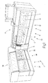
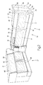
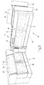
- outer casing 13 comprises a front panel 14 facing vertical front wall 5 of frame 4 and movable, with respect to frame 4, between a closed or bottom limit position - in which it contacts, preferably hermetically, the floor on which frame 4 stands, and is separated from inner casing 12 by a distance defining the depth of a soundproofing air chamber - and an open or top limit position exposing and permitting access to front wall 5 of frame 4 and inner casing 12.
- the bottom limit position of panel 14 contacting the floor has been found to significantly reduce the otherwise fairly high noise level produced by the bottom part of manufacturing machine 2.
- Panel 14 is substantially vertical, and is mounted to slide between said closed and open positions along two substantially vertical guides 15 of frame 4, located on opposite sides of panel 14. More specifically, panel 14 comprises a metal frame 16 supporting glass windows 17.
- Outer casing 13 also comprises a vertical panel 18 which is higher than panel 14 when panel 14 is in the closed position, and which is mounted on hinges 19 to oscillate about a horizontal axis 20.
- panel 18 is rotated about horizontal axis 20 towards manufacturing machine 2 (as shown in Figure 3) to allow panel 14 to move from the closed to the open position.
- a top portion of outer casing 13 is fitted with a horizontal panel 21 mounted on hinges 22 to oscillate about a horizontal axis 23 between a closed position ( Figures 1 and 2) and an open position (Figure 3); and an outer side of outer casing 13 is fitted with two vertical panels 24, each of which is mounted on hinges 25 to oscillate about a vertical axis 26 between a closed position ( Figures 1 and 2) and an open position ( Figure 3) .
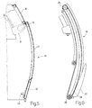
- guides 15 and panel 14 are arc-shaped, and panel 14 is fitted to two slides 27 (only one shown in Figure 6), each of which engages a respective guide 15 and is connected to a powered chain 28 looped about two end gears 29.
- one of gears 29 is rotated by an electric motor (not shown) to move chain 28 and so move the respective slide together with panel 14 along the corresponding guide 15.
- Panel 14 is connected to a further vertical panel 30 which is higher than panel 14 when panel 14 is the closed position, and which is mounted on two slides 31 (only one shown in Figures 5 and 6) which run freely along two respective vertical guides 32 (only one shown in Figures 5 and 6) on opposite sides of panel 30.
- guides 32 and panel 30 are arc-shaped, and guides 32 are parallel to guides 15.
- Panel 14 has a coupling device 33 which engages panel 30 to move panel 30 along guides 32 as panel 14 moves from the closed to the open position. In other words, as it moves from the closed to the open position along guides 15, panel 14 slides over panel 30 so that coupling device 33 engages panel 30 to slide panel 30 along guides 32.
- Filter assembly machine 3 comprises a supporting frame 34 having a front wall 35; and a number of operating devices 36 for processing tobacco and located at front wall 35. More specifically, operating devices 36 comprise a number of drums for feeding cigarettes between a succession of processing stations.
- Filter assembly machine 3 also comprises a casing 37 which can be opened, is movable between an open position and a closed position (shown in Figure 1), covers all the operating devices 36 having moving parts, and is equipped with known safety devices (not shown in detail) for disabling operation of filter assembly machine 3 when casing 37 is not in the closed position.
- Casing 37 provides for reducing the noise level of filter assembly machine 3 within the workplace, and also acts as a safety device for protecting the operators of filter assembly machine 3. In fact, as stated, filter assembly machine 3 can only be operated when casing 37 is in the closed position.
- Casing 37 comprises a vertical panel 38 which can be opened; and a vertical panel 39 which can be opened, is higher than panel 38 when panel 38 is in a closed position, and is mounted on hinges 40 to oscillate about a horizontal axis 41 between an open position and a closed position ( Figures 1-4).
- panel 38 is supported by an arm 42 which is hinged at one end to frame 34 to rotate about a horizontal axis 43, and is hinged at the opposite end to panel 38 to rotate about a horizontal axis 44 parallel to axis 43.
- panel 38 is first rotated with respect to arm 42 about axis 44 ( Figure 8) to move panel 38 with respect to panel 39; arm 42 is then rotated with respect to frame 34 about axis 43, and, at the same time, panel 38 is rotated with respect to arm 42 about axis 44 ( Figure 9) to move panel 38 into the open position.
- unwinding and printing station 9 comprises four side by side operating units 45 comprising an unwinding unit 46, a printing unit 47, a printing unit 48, and a feed unit 49.
- Unwinding unit 46 unwinds strip 10 in controlled manner off a reel 50; printing units 47 and 48 continuously print a series of marks on one surface of strip 10 using inks of two different colours (one for each printing unit 47, 48); and feed unit 49 feeds the strip to rod forming beam 8 at a controlled tension.
- Operating units 45 are preferably modular and the same size.
- unwinding unit 46 and printing units 47 and 48 are modular and the same size.
- unwinding unit 46 comprises a further printing unit for continuously printing a series of marks on one surface of strip 10 using ink of a third colour other than the two colours used on printing units 47 and 48.
- each operating unit 45 is fitted to a respective frame 51 which is mounted on respective telescopic horizontal guides 52 integral with frame 4 of manufacturing machine 2, so as to move between a work position ( Figure 11) and a maintenance position ( Figure 12) in which operating unit 45 is extracted completely from frame 4.
Landscapes
- Engineering & Computer Science (AREA)
- Mechanical Engineering (AREA)
- Manufacturing Of Cigar And Cigarette Tobacco (AREA)
- Filtering Of Dispersed Particles In Gases (AREA)
- Separation Of Particles Using Liquids (AREA)
- Devices For Use In Laboratory Experiments (AREA)
- Fish Paste Products (AREA)
Abstract
Description
Claims (20)
- An automatic machine for processing tobacco articles, the machine comprising:a supporting frame (4) having a front wall (5);a number of operating devices (6) located at the front wall (5) and for processing a succession of articles; andan inner first casing (12) which is supported by the supporting frame (4), can be opened, and covers at least some of the operating devices (6);the machine (2) being characterized by comprising an outer second casing (13) which can be opened, is arranged facing to and close to the inner first casing (12), is independent of the inner first casing (12), and covers at least part of the inner first casing (12).
- A machine as claimed in Claim 1, wherein the inner first casing (12) has safety means for disabling operation of the machine when the inner first casing (12) is not in a closed position.
- A machine as claimed in Claim 2, wherein the outer second casing (13) is movable between a closed position and an open position regardless of the operating condition of the machine.
- A machine as claimed in Claim 3, wherein the outer second casing (13) has actuating means for moving the outer second casing (13) between the closed position and the open position, and which can be activated regardless of the operating condition of the machine.
- A machine as claimed in one of Claims 1 to 4, characterized in that the outer second casing (13) comprises a front panel (14) facing the vertical front wall (5) of the frame (4) and movable, with respect to the frame (4), between a closed or bottom limit position, in which the front panel (14) contacts the floor supporting the frame (4) and is separated from the inner first casing (12) by a distance defining the depth of a soundproofing air chamber, and an open or top limit position, in which the front panel (14) exposes and permits access to the front wall (5) of the frame (4) and the inner first casing (12).
- A machine as claimed in one of Claims 1 to 5, wherein the outer second casing (13) comprises a first panel (14) which is substantially vertical and mounted to slide along two vertical first guides (15), located on opposite sides of the first panel (14), to move between a closed position and an open position.
- A machine as claimed in Claim 6, wherein the first guides (15) and the first panel (14) are arc-shaped.
- A machine as claimed in Claim 6 or 7, wherein the first panel (14) is mounted on two first slides (27), each of which engages a respective first guide (15) and is connected to an endless powered transmission member (28).
- A machine as claimed in Claim 6, 7 or 8, wherein the outer second casing (13) comprises a vertical second panel (30) which is higher than the first panel (14) when the first panel (14) is in the closed position, and which slides freely along two vertical second guides (32) located on opposite sides of the second panel (30).
- A machine as claimed in Claim 9, wherein the second guides (32) are parallel to the first guides (15); the first panel (14) being movable along the first guides (15), and having a coupling device (33) which engages the second panel (30) to move the second panel (30) along the second guides (32) as the first panel (14) moves from the closed position to the open position.
- A machine as claimed in one of Claims 5 to 10, wherein the outer second casing (13) comprises a vertical third panel (18) which is higher than the first panel (14) when the first panel (14) is in the closed position, and which is mounted to rotate about a horizontal axis (20); the third panel (18) being rotated about the horizontal axis to allow the first panel (14) to move from the closed position to the open position.
- A machine as claimed in one of Claims 5 to 11, wherein the first panel (14) comprises a metal frame (16) supporting two glass windows (17).
- A machine as claimed in one of Claims 5 to 12, wherein the machine is a cigarette manufacturing machine (2) comprising a tobacco hopper (7), a rod forming beam (8), an unwinding and printing station (9) for unwinding and printing a paper strip (10), and a rod cutting unit (11); the first panel (14) covering the region of the hopper (7), rod-forming beam (8), and unwinding and printing station (9).
- An automatic machine for processing tobacco articles, the machine (3) comprising:a supporting frame (34) having a front wall (35);a number of operating devices (36) located at the front wall (35) and for processing a succession of articles; anda casing (37) which can be opened and covers at least some of the operating devices (36);the machine (3) being characterized in that the casing (37) comprises a vertical first panel (38) which can be opened; and a vertical second panel (39) which can be opened and is higher than the first panel (38) when the first panel (38) is in a closed position; the first panel (38) being supported by an arm (42) which is hinged at one end to the frame (34) to oscillate about a horizontal first axis (43), and is hinged to the first panel (38) at the opposite end to oscillate about a horizontal second axis (44).
- A machine as claimed in Claim 14, wherein the second panel (39) is mounted to oscillate about a horizontal axis (41) between an open position and a closed position.
- A machine as claimed in Claim 15, wherein the machine is a filter assembly machine (3).
- An automatic cigarette manufacturing machine comprising:a supporting frame (4) having a front wall (5); anda number of operating devices (6) located at the front wall (5) and for processing a succession of articles; wherein the operating devices (6) in turn comprise a tobacco hopper (7), a rod forming beam (8), an unwinding and printing station (9) for unwinding and printing a paper strip (10), and a rod cutting unit (11); the unwinding and printing station (9) comprising four side by side operating units (45) in turn comprising an unwinding unit (46), a first printing unit (47), a second printing unit (48), and a feed unit (49);the machine (2) being characterized in that each operating unit (45) is fitted to a respective frame (51) which is mounted on respective telescopic horizontal guides (52) so as to move between a work position, and a maintenance position in which the operating unit (45) is extracted completely from the supporting frame (4) of the machine.
- A machine as claimed in Claim 17, wherein the operating units (45) are modular and the same size.
- A machine as claimed in Claim 17, wherein the unwinding unit (46) and the printing units (47, 48) are modular and the same size.
- A machine as claimed in Claim 17, 18 or 19, wherein the unwinding unit (46) comprises a third printing unit.
Applications Claiming Priority (2)
| Application Number | Priority Date | Filing Date | Title |
|---|---|---|---|
| ITBO20030704 | 2003-11-21 | ||
| IT000704A ITBO20030704A1 (en) | 2003-11-21 | 2003-11-21 | AUTOMATIC MACHINE FOR THE PROCESSING OF SMOKE ITEMS. |
Publications (3)
| Publication Number | Publication Date |
|---|---|
| EP1532873A2 true EP1532873A2 (en) | 2005-05-25 |
| EP1532873A3 EP1532873A3 (en) | 2005-08-03 |
| EP1532873B1 EP1532873B1 (en) | 2008-02-27 |
Family
ID=34430718
Family Applications (1)
| Application Number | Title | Priority Date | Filing Date |
|---|---|---|---|
| EP04105862A Expired - Lifetime EP1532873B1 (en) | 2003-11-21 | 2004-11-18 | Automatic machine for processing tobacco articles |
Country Status (6)
| Country | Link |
|---|---|
| US (1) | US7509960B2 (en) |
| EP (1) | EP1532873B1 (en) |
| CN (1) | CN100438786C (en) |
| AT (1) | ATE387109T1 (en) |
| DE (1) | DE602004012044T2 (en) |
| IT (1) | ITBO20030704A1 (en) |
Cited By (3)
| Publication number | Priority date | Publication date | Assignee | Title |
|---|---|---|---|---|
| EP2465363A3 (en) * | 2010-12-17 | 2015-11-25 | HAUNI Maschinenbau AG | Bobbin rolling device for the tobacco processing industry |
| IT201800002485A1 (en) * | 2018-02-08 | 2019-08-08 | Gd Spa | Automatic product processing machine and corresponding control method |
| IT201800002486A1 (en) * | 2018-02-08 | 2019-08-08 | Gd Spa | Automatic product processing machine and corresponding control method |
Families Citing this family (3)
| Publication number | Priority date | Publication date | Assignee | Title |
|---|---|---|---|---|
| CN103112247A (en) * | 2012-12-10 | 2013-05-22 | 苏州一致电子制程有限公司 | Thermal transfer printing machine box body |
| DE102013226578A1 (en) * | 2013-12-19 | 2015-06-25 | Hauni Maschinenbau Ag | Machine arrangement and method for controlling a machine arrangement of the tobacco processing industry |
| DE102017128363A1 (en) * | 2017-11-30 | 2019-06-06 | Multivac Sepp Haggenmüller Se & Co. Kg | PACKAGING MACHINE WITH FOLDABLE GUARD COVER |
Family Cites Families (10)
| Publication number | Priority date | Publication date | Assignee | Title |
|---|---|---|---|---|
| GB1442751A (en) | 1972-05-05 | 1976-07-14 | Molins Ltd | Cigarette making machines |
| DE7404292U (en) * | 1973-04-18 | 1978-03-30 | Hauni-Werke Koerber & Co Kg, 2050 Hamburg | MACHINE FOR MANUFACTURING TOBACCO PRODUCTS INDUSTRY |
| US3901349A (en) * | 1974-05-20 | 1975-08-26 | Beloit Corp | Granulator with sound absorbing housing |
| US4129264A (en) * | 1977-09-14 | 1978-12-12 | Semyon Lanin | Soundproof hopper |
| JPS60141272A (en) * | 1983-12-27 | 1985-07-26 | 日本たばこ産業株式会社 | Tobacco producing apparatus |
| DE3624986A1 (en) * | 1986-07-24 | 1988-02-04 | Focke & Co | MACHINE, PARTICULARLY PACKING MACHINE |
| IT1305963B1 (en) | 1998-05-22 | 2001-05-21 | Sasib Tobacco Spa | MODULAR OPERATING MACHINE. |
| DE19943320A1 (en) * | 1999-09-10 | 2001-03-15 | Hauni Maschinenbau Ag | Arrangement for reducing the noise level on production machines in the tobacco processing industry |
| DE19943319A1 (en) * | 1999-09-10 | 2001-03-15 | Hauni Maschinenbau Ag | Arrangement for lowering the noise level in production machines of the tobacco processing industry which are exposed to flowing process air |
| EP1422145A1 (en) | 2002-11-22 | 2004-05-26 | TOPACK Verpackungstechnik GmbH | Room element |
-
2003
- 2003-11-21 IT IT000704A patent/ITBO20030704A1/en unknown
-
2004
- 2004-11-17 US US10/991,330 patent/US7509960B2/en not_active Expired - Fee Related
- 2004-11-18 EP EP04105862A patent/EP1532873B1/en not_active Expired - Lifetime
- 2004-11-18 AT AT04105862T patent/ATE387109T1/en not_active IP Right Cessation
- 2004-11-18 DE DE602004012044T patent/DE602004012044T2/en not_active Expired - Lifetime
- 2004-11-22 CN CNB2004100914254A patent/CN100438786C/en not_active Expired - Fee Related
Cited By (5)
| Publication number | Priority date | Publication date | Assignee | Title |
|---|---|---|---|---|
| EP2465363A3 (en) * | 2010-12-17 | 2015-11-25 | HAUNI Maschinenbau AG | Bobbin rolling device for the tobacco processing industry |
| IT201800002485A1 (en) * | 2018-02-08 | 2019-08-08 | Gd Spa | Automatic product processing machine and corresponding control method |
| IT201800002486A1 (en) * | 2018-02-08 | 2019-08-08 | Gd Spa | Automatic product processing machine and corresponding control method |
| WO2019155420A1 (en) * | 2018-02-08 | 2019-08-15 | G.D Società per Azioni | Automatic machine for the production or packaging of smoking, sanitary, foodstuff, or pharmaceutical products and corresponding control method |
| WO2019155421A1 (en) * | 2018-02-08 | 2019-08-15 | G.D Società per Azioni | Automatic machine for the processing of products and corresponding control method |
Also Published As
| Publication number | Publication date |
|---|---|
| DE602004012044D1 (en) | 2008-04-10 |
| EP1532873A3 (en) | 2005-08-03 |
| CN100438786C (en) | 2008-12-03 |
| EP1532873B1 (en) | 2008-02-27 |
| DE602004012044T2 (en) | 2009-03-12 |
| ATE387109T1 (en) | 2008-03-15 |
| ITBO20030704A1 (en) | 2005-05-22 |
| CN1623453A (en) | 2005-06-08 |
| US20050150506A1 (en) | 2005-07-14 |
| US7509960B2 (en) | 2009-03-31 |
Similar Documents
| Publication | Publication Date | Title |
|---|---|---|
| EP1532873B1 (en) | Automatic machine for processing tobacco articles | |
| GB2360251A (en) | A web-fed rotary printing machine with entry modules arranged between printing units | |
| ITBO20010776A1 (en) | DEVICE FOR THE CONNECTION BETWEEN A DISPENSING UNIT AND A UNIT USING SMOKE PRODUCTS | |
| US2651992A (en) | Web printing press | |
| US4882938A (en) | Pick-up unit for withdrawing cigarette samples from a mass of cigarettes | |
| ITBO20010604A1 (en) | OUTPUT UNIT OF A CIGARETTE PACKING MACHINE | |
| WO2002020377A1 (en) | Equipment and method for handling returnable bottles | |
| AU9171382A (en) | Roll baling machine with air spring tensioner for apron means | |
| IT9003649A1 (en) | DEVICE FOR THE AUTOMATIC FEEDING OF STACKS OF BLANKS TO A MACHINE USING FOR EXAMPLE A WRAPPING MACHINE. | |
| EP1472937B9 (en) | A machine for manufacturing tobacco products | |
| US4729812A (en) | Service apparatus for machines using continuous strips of paper forms or sheets | |
| FI63178C (en) | KAPNINGSMASKIN FOER SLANGAR | |
| JP3871387B2 (en) | Cleaning device for light receiving sensor | |
| JP2007014335A (en) | Apparatus for feeding filter to filter tip attachment machine | |
| ES8207453A1 (en) | Torch cutting machine with sound proofing means. | |
| CN203276394U (en) | Paper money processing device | |
| US4586323A (en) | Noise control system for textile machinery | |
| CN215320639U (en) | 3D printer | |
| ITBO980374A1 (en) | AUTOMATIC FEEDING GROUP OF A REEL OF MATERIAL IN TAPE TO A USING MACHINE. | |
| JP3774820B2 (en) | Slide cover device | |
| JPS62670B2 (en) | ||
| JPH06270094A (en) | Belt-like rice cake cutter | |
| US20020000146A1 (en) | Bread-cutting machine with crumb deflector | |
| ITVI970179A1 (en) | SEMI-AUTOMATIC UNLOADING GRASS MACHINE | |
| EP1902635B1 (en) | A machine for manufacturing cigarette filters |
Legal Events
| Date | Code | Title | Description |
|---|---|---|---|
| PUAI | Public reference made under article 153(3) epc to a published international application that has entered the european phase |
Free format text: ORIGINAL CODE: 0009012 |
|
| AK | Designated contracting states |
Kind code of ref document: A2 Designated state(s): AT BE BG CH CY CZ DE DK EE ES FI FR GB GR HU IE IS IT LI LU MC NL PL PT RO SE SI SK TR |
|
| AX | Request for extension of the european patent |
Extension state: AL HR LT LV MK YU |
|
| PUAL | Search report despatched |
Free format text: ORIGINAL CODE: 0009013 |
|
| AK | Designated contracting states |
Kind code of ref document: A3 Designated state(s): AT BE BG CH CY CZ DE DK EE ES FI FR GB GR HU IE IS IT LI LU MC NL PL PT RO SE SI SK TR |
|
| AX | Request for extension of the european patent |
Extension state: AL HR LT LV MK YU |
|
| 17P | Request for examination filed |
Effective date: 20060201 |
|
| AKX | Designation fees paid |
Designated state(s): AT BE BG CH CY CZ DE DK EE ES FI FR GB GR HU IE IS IT LI LU MC NL PL PT RO SE SI SK TR |
|
| 17Q | First examination report despatched |
Effective date: 20060623 |
|
| GRAP | Despatch of communication of intention to grant a patent |
Free format text: ORIGINAL CODE: EPIDOSNIGR1 |
|
| GRAS | Grant fee paid |
Free format text: ORIGINAL CODE: EPIDOSNIGR3 |
|
| GRAA | (expected) grant |
Free format text: ORIGINAL CODE: 0009210 |
|
| AK | Designated contracting states |
Kind code of ref document: B1 Designated state(s): AT BE BG CH CY CZ DE DK EE ES FI FR GB GR HU IE IS IT LI LU MC NL PL PT RO SE SI SK TR |
|
| REG | Reference to a national code |
Ref country code: GB Ref legal event code: FG4D |
|
| REG | Reference to a national code |
Ref country code: CH Ref legal event code: EP |
|
| REG | Reference to a national code |
Ref country code: IE Ref legal event code: FG4D |
|
| REF | Corresponds to: |
Ref document number: 602004012044 Country of ref document: DE Date of ref document: 20080410 Kind code of ref document: P |
|
| REG | Reference to a national code |
Ref country code: CH Ref legal event code: NV Representative=s name: HEPP, WENGER & RYFFEL AG |
|
| PG25 | Lapsed in a contracting state [announced via postgrant information from national office to epo] |
Ref country code: FI Free format text: LAPSE BECAUSE OF FAILURE TO SUBMIT A TRANSLATION OF THE DESCRIPTION OR TO PAY THE FEE WITHIN THE PRESCRIBED TIME-LIMIT Effective date: 20080227 Ref country code: ES Free format text: LAPSE BECAUSE OF FAILURE TO SUBMIT A TRANSLATION OF THE DESCRIPTION OR TO PAY THE FEE WITHIN THE PRESCRIBED TIME-LIMIT Effective date: 20080607 Ref country code: IS Free format text: LAPSE BECAUSE OF FAILURE TO SUBMIT A TRANSLATION OF THE DESCRIPTION OR TO PAY THE FEE WITHIN THE PRESCRIBED TIME-LIMIT Effective date: 20080627 |
|
| NLV1 | Nl: lapsed or annulled due to failure to fulfill the requirements of art. 29p and 29m of the patents act | ||
| PG25 | Lapsed in a contracting state [announced via postgrant information from national office to epo] |
Ref country code: AT Free format text: LAPSE BECAUSE OF FAILURE TO SUBMIT A TRANSLATION OF THE DESCRIPTION OR TO PAY THE FEE WITHIN THE PRESCRIBED TIME-LIMIT Effective date: 20080227 |
|
| PG25 | Lapsed in a contracting state [announced via postgrant information from national office to epo] |
Ref country code: PL Free format text: LAPSE BECAUSE OF FAILURE TO SUBMIT A TRANSLATION OF THE DESCRIPTION OR TO PAY THE FEE WITHIN THE PRESCRIBED TIME-LIMIT Effective date: 20080227 Ref country code: BE Free format text: LAPSE BECAUSE OF FAILURE TO SUBMIT A TRANSLATION OF THE DESCRIPTION OR TO PAY THE FEE WITHIN THE PRESCRIBED TIME-LIMIT Effective date: 20080227 Ref country code: SI Free format text: LAPSE BECAUSE OF FAILURE TO SUBMIT A TRANSLATION OF THE DESCRIPTION OR TO PAY THE FEE WITHIN THE PRESCRIBED TIME-LIMIT Effective date: 20080227 |
|
| PG25 | Lapsed in a contracting state [announced via postgrant information from national office to epo] |
Ref country code: CZ Free format text: LAPSE BECAUSE OF FAILURE TO SUBMIT A TRANSLATION OF THE DESCRIPTION OR TO PAY THE FEE WITHIN THE PRESCRIBED TIME-LIMIT Effective date: 20080227 Ref country code: SE Free format text: LAPSE BECAUSE OF FAILURE TO SUBMIT A TRANSLATION OF THE DESCRIPTION OR TO PAY THE FEE WITHIN THE PRESCRIBED TIME-LIMIT Effective date: 20080527 Ref country code: SK Free format text: LAPSE BECAUSE OF FAILURE TO SUBMIT A TRANSLATION OF THE DESCRIPTION OR TO PAY THE FEE WITHIN THE PRESCRIBED TIME-LIMIT Effective date: 20080227 Ref country code: DK Free format text: LAPSE BECAUSE OF FAILURE TO SUBMIT A TRANSLATION OF THE DESCRIPTION OR TO PAY THE FEE WITHIN THE PRESCRIBED TIME-LIMIT Effective date: 20080227 Ref country code: PT Free format text: LAPSE BECAUSE OF FAILURE TO SUBMIT A TRANSLATION OF THE DESCRIPTION OR TO PAY THE FEE WITHIN THE PRESCRIBED TIME-LIMIT Effective date: 20080721 Ref country code: NL Free format text: LAPSE BECAUSE OF FAILURE TO SUBMIT A TRANSLATION OF THE DESCRIPTION OR TO PAY THE FEE WITHIN THE PRESCRIBED TIME-LIMIT Effective date: 20080227 |
|
| PG25 | Lapsed in a contracting state [announced via postgrant information from national office to epo] |
Ref country code: RO Free format text: LAPSE BECAUSE OF FAILURE TO SUBMIT A TRANSLATION OF THE DESCRIPTION OR TO PAY THE FEE WITHIN THE PRESCRIBED TIME-LIMIT Effective date: 20080227 |
|
| EN | Fr: translation not filed | ||
| PLBE | No opposition filed within time limit |
Free format text: ORIGINAL CODE: 0009261 |
|
| STAA | Information on the status of an ep patent application or granted ep patent |
Free format text: STATUS: NO OPPOSITION FILED WITHIN TIME LIMIT |
|
| 26N | No opposition filed |
Effective date: 20081128 |
|
| PG25 | Lapsed in a contracting state [announced via postgrant information from national office to epo] |
Ref country code: FR Free format text: LAPSE BECAUSE OF FAILURE TO SUBMIT A TRANSLATION OF THE DESCRIPTION OR TO PAY THE FEE WITHIN THE PRESCRIBED TIME-LIMIT Effective date: 20081219 Ref country code: EE Free format text: LAPSE BECAUSE OF FAILURE TO SUBMIT A TRANSLATION OF THE DESCRIPTION OR TO PAY THE FEE WITHIN THE PRESCRIBED TIME-LIMIT Effective date: 20080227 Ref country code: BG Free format text: LAPSE BECAUSE OF FAILURE TO SUBMIT A TRANSLATION OF THE DESCRIPTION OR TO PAY THE FEE WITHIN THE PRESCRIBED TIME-LIMIT Effective date: 20080527 |
|
| PG25 | Lapsed in a contracting state [announced via postgrant information from national office to epo] |
Ref country code: MC Free format text: LAPSE BECAUSE OF NON-PAYMENT OF DUE FEES Effective date: 20081130 |
|
| PG25 | Lapsed in a contracting state [announced via postgrant information from national office to epo] |
Ref country code: CY Free format text: LAPSE BECAUSE OF FAILURE TO SUBMIT A TRANSLATION OF THE DESCRIPTION OR TO PAY THE FEE WITHIN THE PRESCRIBED TIME-LIMIT Effective date: 20080227 |
|
| PG25 | Lapsed in a contracting state [announced via postgrant information from national office to epo] |
Ref country code: IT Free format text: LAPSE BECAUSE OF FAILURE TO SUBMIT A TRANSLATION OF THE DESCRIPTION OR TO PAY THE FEE WITHIN THE PRESCRIBED TIME-LIMIT Effective date: 20080227 |
|
| PG25 | Lapsed in a contracting state [announced via postgrant information from national office to epo] |
Ref country code: IE Free format text: LAPSE BECAUSE OF NON-PAYMENT OF DUE FEES Effective date: 20081118 |
|
| PGFP | Annual fee paid to national office [announced via postgrant information from national office to epo] |
Ref country code: CH Payment date: 20091124 Year of fee payment: 6 Ref country code: DE Payment date: 20091127 Year of fee payment: 6 |
|
| PGFP | Annual fee paid to national office [announced via postgrant information from national office to epo] |
Ref country code: GB Payment date: 20091125 Year of fee payment: 6 |
|
| PG25 | Lapsed in a contracting state [announced via postgrant information from national office to epo] |
Ref country code: LU Free format text: LAPSE BECAUSE OF NON-PAYMENT OF DUE FEES Effective date: 20081118 Ref country code: HU Free format text: LAPSE BECAUSE OF FAILURE TO SUBMIT A TRANSLATION OF THE DESCRIPTION OR TO PAY THE FEE WITHIN THE PRESCRIBED TIME-LIMIT Effective date: 20080828 |
|
| PG25 | Lapsed in a contracting state [announced via postgrant information from national office to epo] |
Ref country code: TR Free format text: LAPSE BECAUSE OF FAILURE TO SUBMIT A TRANSLATION OF THE DESCRIPTION OR TO PAY THE FEE WITHIN THE PRESCRIBED TIME-LIMIT Effective date: 20080227 |
|
| PG25 | Lapsed in a contracting state [announced via postgrant information from national office to epo] |
Ref country code: GR Free format text: LAPSE BECAUSE OF FAILURE TO SUBMIT A TRANSLATION OF THE DESCRIPTION OR TO PAY THE FEE WITHIN THE PRESCRIBED TIME-LIMIT Effective date: 20080528 |
|
| REG | Reference to a national code |
Ref country code: CH Ref legal event code: PL |
|
| GBPC | Gb: european patent ceased through non-payment of renewal fee |
Effective date: 20101118 |
|
| PG25 | Lapsed in a contracting state [announced via postgrant information from national office to epo] |
Ref country code: CH Free format text: LAPSE BECAUSE OF NON-PAYMENT OF DUE FEES Effective date: 20101130 Ref country code: LI Free format text: LAPSE BECAUSE OF NON-PAYMENT OF DUE FEES Effective date: 20101130 |
|
| REG | Reference to a national code |
Ref country code: DE Ref legal event code: R119 Ref document number: 602004012044 Country of ref document: DE Effective date: 20110601 Ref country code: DE Ref legal event code: R119 Ref document number: 602004012044 Country of ref document: DE Effective date: 20110531 |
|
| PG25 | Lapsed in a contracting state [announced via postgrant information from national office to epo] |
Ref country code: GB Free format text: LAPSE BECAUSE OF NON-PAYMENT OF DUE FEES Effective date: 20101118 |
|
| PG25 | Lapsed in a contracting state [announced via postgrant information from national office to epo] |
Ref country code: DE Free format text: LAPSE BECAUSE OF NON-PAYMENT OF DUE FEES Effective date: 20110531 |