EP1532700B1 - Seal for an electrochemical cell - Google Patents
Seal for an electrochemical cell Download PDFInfo
- Publication number
- EP1532700B1 EP1532700B1 EP03791795A EP03791795A EP1532700B1 EP 1532700 B1 EP1532700 B1 EP 1532700B1 EP 03791795 A EP03791795 A EP 03791795A EP 03791795 A EP03791795 A EP 03791795A EP 1532700 B1 EP1532700 B1 EP 1532700B1
- Authority
- EP
- European Patent Office
- Prior art keywords
- vent
- seal member
- electrochemical cell
- cell
- cover
- Prior art date
- Legal status (The legal status is an assumption and is not a legal conclusion. Google has not performed a legal analysis and makes no representation as to the accuracy of the status listed.)
- Expired - Lifetime
Links
Images


Classifications
-
- H—ELECTRICITY
- H01—ELECTRIC ELEMENTS
- H01M—PROCESSES OR MEANS, e.g. BATTERIES, FOR THE DIRECT CONVERSION OF CHEMICAL ENERGY INTO ELECTRICAL ENERGY
- H01M50/00—Constructional details or processes of manufacture of the non-active parts of electrochemical cells other than fuel cells, e.g. hybrid cells
- H01M50/30—Arrangements for facilitating escape of gases
- H01M50/342—Non-re-sealable arrangements
- H01M50/3425—Non-re-sealable arrangements in the form of rupturable membranes or weakened parts, e.g. pierced with the aid of a sharp member
-
- H—ELECTRICITY
- H01—ELECTRIC ELEMENTS
- H01M—PROCESSES OR MEANS, e.g. BATTERIES, FOR THE DIRECT CONVERSION OF CHEMICAL ENERGY INTO ELECTRICAL ENERGY
- H01M50/00—Constructional details or processes of manufacture of the non-active parts of electrochemical cells other than fuel cells, e.g. hybrid cells
- H01M50/10—Primary casings; Jackets or wrappings
- H01M50/183—Sealing members
- H01M50/186—Sealing members characterised by the disposition of the sealing members
- H01M50/188—Sealing members characterised by the disposition of the sealing members the sealing members being arranged between the lid and terminal
-
- H—ELECTRICITY
- H01—ELECTRIC ELEMENTS
- H01M—PROCESSES OR MEANS, e.g. BATTERIES, FOR THE DIRECT CONVERSION OF CHEMICAL ENERGY INTO ELECTRICAL ENERGY
- H01M50/00—Constructional details or processes of manufacture of the non-active parts of electrochemical cells other than fuel cells, e.g. hybrid cells
- H01M50/10—Primary casings; Jackets or wrappings
- H01M50/183—Sealing members
- H01M50/19—Sealing members characterised by the material
- H01M50/193—Organic material
-
- H—ELECTRICITY
- H01—ELECTRIC ELEMENTS
- H01M—PROCESSES OR MEANS, e.g. BATTERIES, FOR THE DIRECT CONVERSION OF CHEMICAL ENERGY INTO ELECTRICAL ENERGY
- H01M50/00—Constructional details or processes of manufacture of the non-active parts of electrochemical cells other than fuel cells, e.g. hybrid cells
- H01M50/10—Primary casings; Jackets or wrappings
- H01M50/102—Primary casings; Jackets or wrappings characterised by their shape or physical structure
- H01M50/107—Primary casings; Jackets or wrappings characterised by their shape or physical structure having curved cross-section, e.g. round or elliptic
-
- Y—GENERAL TAGGING OF NEW TECHNOLOGICAL DEVELOPMENTS; GENERAL TAGGING OF CROSS-SECTIONAL TECHNOLOGIES SPANNING OVER SEVERAL SECTIONS OF THE IPC; TECHNICAL SUBJECTS COVERED BY FORMER USPC CROSS-REFERENCE ART COLLECTIONS [XRACs] AND DIGESTS
- Y02—TECHNOLOGIES OR APPLICATIONS FOR MITIGATION OR ADAPTATION AGAINST CLIMATE CHANGE
- Y02E—REDUCTION OF GREENHOUSE GAS [GHG] EMISSIONS, RELATED TO ENERGY GENERATION, TRANSMISSION OR DISTRIBUTION
- Y02E60/00—Enabling technologies; Technologies with a potential or indirect contribution to GHG emissions mitigation
- Y02E60/10—Energy storage using batteries
Definitions
- This invention generally relates to ventable seals for pressurized containers and, more particularly, to ventable seals for electrochemical cells.
- Electrochemical cells such as cylindrical alkaline electrochemical cells, employ two electrochemically active material and an aqueous electrolyte.
- the electrochemically active materials are typically manganese dioxide and zinc. These materials are conventionally housed in a cylindrical elongated container that is open on one end so that the electrochemically active materials and electrolyte can be inserted therein during the cell manufacturing process.
- a closure assembly that incorporates a disc shaped polymeric seal member, a rigid inner cover and an elongated metallic current collector that projects through the center of the seal member, closes the open end of the container.
- the seal member usually includes a hub, which surrounds the collector, and a thin diaphragm integrally molded into the central region of the seal body. The function of the diaphragm is to rupture and release gas from within the cell when the internal pressure becomes too high.
- the collector provides a conductive path between the zinc and one of the cell's terminal covers which is located on an end of the cell.
- vent assemblies have been made more volume efficient by redesigning them to require fewer components and yet operate more reliably than previously known vent assemblies. As the volume occupied by the vent assembly has decreased, the problem of a vented seal "resealing" against another component of the vent assembly has become more apparent.
- the simultaneous production of gas and increase in temperature causes the polymeric seal, which is typically made of nylon, to become soft and lose some of its structural rigidity.
- the thin ventable portion of the seal may become elongated due to both the heating of the nylon and the increase in internal pressure. Consequently, when the softened and distorted seal ruptures in response to the pressure buildup, an initial quantity of gas may escape from within the cell but the tear in the ruptured seal may be resealed when the softened ruptured seal contacts the smooth inner surface of the terminal cover and reseals against the terminal cover.
- This problem is particularly acute with low volume vent assemblies wherein the distance between the seal member and other components, such as the cell's cover, is very small. If the ruptured seal does reseal against the cover and the cell continues to generate gas, the cell may eventually experience a crimp release wherein the crimped connection between the seal and container is broken and the vent assembly is forcefully ejected from the container.
- US 6,270,918 B1 discloses a seal assembly that utilizes a seal member and an inner cover with openings incorporated therein.
- the seal member directly abuts the inner cover.
- An outer cover is secured to the seal assembly and forms a contact terminal of the cell. If the cell's pressure increases beyond an acceptable limit, the seal member ruptures thereby allowing gas to escape through the openings in both the inner cover and contact terminal. While the described seal assembly does safely vent an electrochemical cell, the seal assembly relies upon the use of the inner cover. Unfortunately, the inner cover occupies space within the cell that could be better used to store more of the cell's electrochemically active materials.
- US-A-5 422 201 describes an electrochemical cell including a current collector assembly having a current collector, a seal and a compression means, wherein the compression means and collector exert minimum tension and maximum compressive stresses on the seal thereby avoiding leakage of electrolyte either through or around the seal. At least one portion of the seal body may be made thinner in cross-section than the reinforced areas so that the seal can rupture if the cell's internal pressure exceeds a predetermined limit. An arc shaped groove or vent line is not described.
- the present invention provides an electrochemical cell with a vent assembly that reliably prevents resealing of a vented seal member.
- the vent assembly occupies a minimum amount of space within the cell and is inexpensive to produce.
- the electrochemical cell of the present invention comprises
- FIG. 3 there is shown a cross-sectional view of an assembled electrochemical cell of this invention.
- the cell components are the container 10, first electrode 12 positioned adjacent the interior surface of container 10, separator 14 contacting the interior surface 16 of first electrode 12, second electrode 18 disposed within the cavity defined by separator 14 and vent assembly 20 secured to container 10.
- Container 10 has an open end 22, a closed end 24 and a sidewall 26 therebetween.
- the closed end 24, sidewall 26 and vent assembly 20 define a cavity in which the cell's electrodes are housed.
- seal member 28 Shown in Figs. 1 and 2 is an embodiment of seal member 28 which has several sections that perform a variety of functions.
- the perimeter of seal member 28 is defined by upstanding wall 34 which forms an electrically insulating barrier between container 10 which serves as the current collector for first electrode 12, and terminal cover 32 which serves as the external contact for second electrode 18.
- the interior surface of perimeter wall 34 also referred to herein as the upstanding wall, forms one side of a cover reception channel 76 in seal member 28 into which the rollback edge 36 of cover 32 is inserted.
- buttress wall 38 Located adjacent the interior surface of rollback edge 36 is buttress wall 38 which extends above diaphragm region 40.
- diaphragm region 40 includes an elbow 42 which joins two annular sections of diaphragm 40 at an obtuse angle.
- vent flap 48 When diaphragm 40 responds to an excessive increase in internal pressure by inverting and tearing at vent line 44, diaphragm 40 forms a vent flap 48, see Figs. 5 and 6 , with a distal end 50 and a proximate end 52. Vent flap 48 is specifically designed to rotate toward terminal cover 32 so that an opening 78 is created in seal member 28. Pressurized gas within the cell escapes to the environment beyond the cell by passing through the vented opening in the seal member and then through opening 54 in terminal cover 32. Vent flap 48 is made to rotate around hinge area 56, which is located at the proximate end 52 of vent flap 48. In a preferred embodiment, hinge area 56 forms an arc that is concentric with the central opening 30 in seal member 28.
- Hinge 56 is the arc shaped line in the seal member about which the vent flap rotates when the seal is ruptured.
- the hinge coincides with at least a portion of first edge 64 of diaphragm 40.
- the hinge forms an arc or a circle that is concentric with the vent assembly's longitudinal axis.
- Abutting and defining another edge of diaphragm 40 is second edge 66.
- First edge 64 and second edge 66 are concentric with one another and the vent assembly's longitudinal axis.
- Second edge 66 comprises a grooved section and a nongrooved section.
- the grooved section defines the location of vent 44.
- the nongrooved section forms a nonventable interface between a portion of diaphragm 40 and hub 70.
- the nonventable interface forms anchor 82.
- the function of anchor 82 is to secure vent flap 48 to both diaphragm region 40 and hub 70, thereby ensuring that vent flap 48 does not contact terminal cover 32 and form a 360° seal against the interior surface of the terminal cover when the cell's internal pressure causes seal member 28 to rupture at vent line 44.
- the arc formed by vent line 44 should be at least 180°, more preferably approximately 220° and most preferably not more than 250°.
- the portion of diaphragm 40 that abuts hub 70 and does not include vent line 44 forms an anchor 82.
- the arc formed by anchor 82 should be at least 30°, more preferably approximately 100° and most preferably less than 180°.
- opening 78 is formed by tearing the diaphragm at vent line 44. Opening 78 may extend from one end of vent line 44 to the other end of vent line 44 provided opening 78 does not extend into the nongrooved section of second edge 66. Alternatively, opening 78 may extend around a portion of vent line 44 as shown in Fig. 4 .
- the size of opening 78 is not critical provided it is large enough for the gas within the cell to rapidly escape when the cell vents.
- the arc of anchor 82 and the arc of vent line 44 form a complete circle.
- vent flap 48 Relative to the elevation of the vent assembly's longitudinal axis 58, the elevations of hinge 56, terminal cover 32 and vent line 44 in seal member 28 are critical to preventing the resealing of vent flap 48 against the interior surface of cover 32. If the distal end 50 of vent flap 48 is allowed to contact cover 32 and the cell continues to generate gas after the diaphragm has ruptured, as would occur when a cell has been inserted backwards in a multicell device and is subsequently charged by the other cells, then the flap is forcefully pressed against cover 32 thereby blocking further release of gas through the seal member and cover. If the internal pressure exceeds the container's ability to remain crimped over the perimeter of the seal member, then the vent assembly may be rapidly expelled from the container. Some of the cell's other components, such as electrolyte and portions of the anode, may also be forcefully thrown from the container.
- the elevation of the hinge must be closer to the elevation of the vent than to the elevation of the cover's central portion.
- the elevations of the hinge, vent and cover are determined relative to the longitudinal axis 58 of vent assembly 20.
- the longitudinal axis 58 of the vent assembly is concentric with the longitudinal axis of container 10.
- the highest elevation within the vent assembly is the surface of the terminal cover's central portion. Any point along the vent assembly's axis that is between the terminal cover and the end of current collector 30 that contacts second electrode 18 is considered to be lower than the highest elevation.
- the elevation of any feature in the vent assembly is determined by connecting a straight line from the feature in question to the vent assembly's longitudinal axis provided the axis and straight line meet at a right angle.
- the feature with its straight line closest to the surface of terminal cover 32 is considered to be higher in elevation than the other feature.
- the elevations of cover 32, hinge 56 and vent 44, relative to the longitudinal axis of the vent assembly correspond to points A, B and C, respectively.
- the elevation of hinge 56 (point B) must be closer to the elevation of vent 44 (point C) than to the elevation of the junction of collector 30 and the cover's central portion (point A).
- the elevation of hinge 56 is greater than the elevation of vent 44.
- vent flap 48 which is forced to rotate through the vent deflection zone, toward cover 32, by the pressurized gas as it escapes from the cell.
- the vent deflection zone is the space between diaphragm 40 and terminal cover 32. In Fig. 3 , the vent deflection zone is identified with parallel diagonal lines. To ensure proper operation of the vent assembly, the vent deflection zone should not be obstructed with any objects that would impede movement of the vent flap. For example, the existence of a support member 62, shown in Fig. 7 , would inhibit proper operation of the vent flap. Consequently, in a preferred embodiment, the vent assembly of this invention includes a seal member, a current collector and a single cover that also functions as one of the cell's terminals.
- hub base 68 Inwardly disposed from second edge 66 is hub base 68, hub 70 and collector 30.
- Hub base 68 is thicker than diaphragm 40.
- Hub 70 abuts hub base 68 at a right angle.
- Hub 70 defines central opening 30 in seal member 28.
- Seal member 28 is typically made as a single component by injection molding a polymeric material into a cavity and then allowing the part to solidify.
- Materials from which the seal member may be made include: nylon 6, 6; polypropylene; and impact modified polystyrene as described in US 6,306,537 .
- vent assembly An optional component of the vent assembly shown in Figs. 3 and 6 is compression brushing 46.
- the exterior circumferential surface 72 of the compression bushing is made to align with vent 44.
- vent assemblies that do not include a compression bushing the vent is made to align with the outside diameter of hub 70.
- Terminal cover 32 is a generally cup-shaped component made of nickel-plated steel.
- the perimeter 36 of cover 32 is formed by rolling back the edge of the cover upon itself to create a double thickness of material that is approximately perpendicular to the central portion 74 of cover 32. Between the covered central portion and its perimeter, the cover is contoured through a series of bends. The cover's central region 74 is recessed relative to the cover's rolled back edge 36.
- cover 32 When cover 32 is inserted into the seal member's cover reception cavity 76 and the vent assembly is crimped into the open end of container 10, the cover acts like a spring that compresses the seal member's upstanding wall 34 against the interior surface of container 10.
- the vent assembly does not need to include a separate component to force the seal member's perimeter wall against the container.
- First electrode 12 is a mixture of manganese dioxide, graphite and an aqueous solution containing potassium hydroxide.
- the electrode is formed by disposing a quantity of the mixture into the open ended container and then using a ram to mold the mixture into a solid tubular shape that defines a cavity which is concentric with the sidewall of the container.
- the cathode may be formed by preforming a plurality of rings from the mixture comprising manganese dioxide and then inserting the rings into the container to form the tubularly shaped first electrode.
- Second electrode 18 is a homogenous mixture of an aqueous alkaline electrolyte, zinc powder, and a gelling agent such as crosslinked polyacrylic acid.
- the aqueous alkaline electrolyte comprises an alkaline metal hydroxide such as potassium hydroxide, sodium hydroxide, or mixtures thereof. Potassium hydroxide is preferred.
- the gelling agent suitable for use in a cell of this invention can be a crosslinked polyacrylic acid, such as Carbopol 940®, which is available from Noveon, Inc., Cleveland, Ohio, USA. Carboxymethylcellulose, polyacrylamide and sodium polyacrylate are examples of other gelling agents that are suitable for use in an alkaline electrolyte solution.
- the zinc powder may be pure zinc or an alloy comprising an appropriate amount of one or more of the metals selected from the group consisting of indium, lead, bismuth, lithium, calcium and aluminum.
- a suitable anode mixture contains 67 weight percent zinc powder, 0.50 weight percent gelling agent and 32.5 weight percent alkaline electrolyte having 40 weight percent potassium hydroxide.
- the quantity of zinc can range from 63 percent by weight to 70 percent by weight of the anode.
- Other components such as gassing inhibitors, organic or inorganic anticorrosive agents, binders or surfactants may be optionally added to the ingredients listed above.
- gassing inhibitors or anticorrosive agents can include indium salts (such as indium hydroxide), perfluoroalkyl ammonium salts, alkali metal sulfides, etc.
- surfactants can include polyethylene oxide, polyethylene alkylethers, perfluoroalkyl compounds, and the like.
- the second electrode may be manufactured by combining the ingredients described above into a ribbon blender or drum mixer and then working the mixture into a wet slurry.
- Electrolyte suitable for use in a cell of this invention is a "thirty-seven percent by weight aqueous solution of potassium hydroxide.
- the electrolyte may be incorporated into the cell by disposing a quantity of the fluid electrolyte into the cavity defined by the first electrode.
- the electrolyte may also be introduced into the cell by allowing the gelling medium to absorb an aqueous solution of potassium hydroxide during the process used to manufacture the second electrode.
- the method used to incorporate electrolyte into the cell is not critical provided the electrolyte is in contact with the first electrode 12, second electrode 18 and separator 14.
- a quantity of an aqueous potassium hydroxide solution is incorporated into the cell.
- the solution serves as the cell's electrolyte.
- the electrolyte may be incorporated into the cell by allowing the gelling agent in the second electrode to absorb the electrolyte during the electrode manufacturing process which occurs prior to inserting the second electrode into the coiled separator.
- a quantity of electrolyte may be dispensed into the partially completed cell any time after the first electrode has been inserted into the container and prior to closing the cell.
- Separator 14 may be made from nonwoven fibers.
- One of the separator's functions is to provide a barrier at the interface of the first and second electrodes.
- the barrier must be electrically insulating and ionically permeable.
Landscapes
- Chemical & Material Sciences (AREA)
- Chemical Kinetics & Catalysis (AREA)
- Electrochemistry (AREA)
- General Chemical & Material Sciences (AREA)
- Gas Exhaust Devices For Batteries (AREA)
- Sealing Battery Cases Or Jackets (AREA)
Abstract
Description
- This invention generally relates to ventable seals for pressurized containers and, more particularly, to ventable seals for electrochemical cells.
- Electrochemical cells, such as cylindrical alkaline electrochemical cells, employ two electrochemically active material and an aqueous electrolyte. The electrochemically active materials are typically manganese dioxide and zinc. These materials are conventionally housed in a cylindrical elongated container that is open on one end so that the electrochemically active materials and electrolyte can be inserted therein during the cell manufacturing process. A closure assembly that incorporates a disc shaped polymeric seal member, a rigid inner cover and an elongated metallic current collector that projects through the center of the seal member, closes the open end of the container. The seal member usually includes a hub, which surrounds the collector, and a thin diaphragm integrally molded into the central region of the seal body. The function of the diaphragm is to rupture and release gas from within the cell when the internal pressure becomes too high. The collector provides a conductive path between the zinc and one of the cell's terminal covers which is located on an end of the cell.
- Manufacturers of electrochemical batteries constantly strive to improve the performance of their products in a wide variety of battery powered devices. A key objective of most battery manufacturers is to improve the amount of time that a battery will power a device. One strategy to accomplish this objective is to minimize the volume occupied by the cell's nonelectrochemically active components, such as the cell's vent assembly, thereby leaving more volume within the cell available for the electrochemically active components. In recent years, vent assemblies have been made more volume efficient by redesigning them to require fewer components and yet operate more reliably than previously known vent assemblies. As the volume occupied by the vent assembly has decreased, the problem of a vented seal "resealing" against another component of the vent assembly has become more apparent. This problem can occur in primary batteries, also known as nonrechargeable batteries, if they are charged by other batteries. While most batteries are used in a conventional manner, a small percentage of batteries are exposed to an abusive condition such as when a primary battery is inadvertently placed in a device such that the battery's positive and negative terminals are reversed. This problem could occur, for example, in some commercially available flashlights that are powered by eight AA size alkaline batteries. Typically, the batteries are inserted into two elongated chambers containing four batteries each. According to the instructions that accompany the flashlight, the batteries must be inserted "in series," which means that the positive terminal of one battery contacts the negative terminal of an adjoining battery. Unfortunately, some consumers fail to comply with the instructions that are normally included with the device and accidentally insert one of the cells backwards. If this occurs with the second or third battery in a cavity containing four batteries, then the cell inserted backwards will be charged by one or more of the properly inserted cells when the light's switch is moved to the "on" position. Charging the battery that has been inserted backwards generates significant quantities of heat and gas within the battery. In some situations, the external temperature of the battery could exceed 65° C. The increase in temperature increases the pressure within the cell. In addition to increasing the temperature of the battery, the chemical reactions that take place during the charging of the cell generate gas that substantially increases pressure within the cell. The simultaneous production of gas and increase in temperature causes the polymeric seal, which is typically made of nylon, to become soft and lose some of its structural rigidity. The thin ventable portion of the seal may become elongated due to both the heating of the nylon and the increase in internal pressure. Consequently, when the softened and distorted seal ruptures in response to the pressure buildup, an initial quantity of gas may escape from within the cell but the tear in the ruptured seal may be resealed when the softened ruptured seal contacts the smooth inner surface of the terminal cover and reseals against the terminal cover. This problem is particularly acute with low volume vent assemblies wherein the distance between the seal member and other components, such as the cell's cover, is very small. If the ruptured seal does reseal against the cover and the cell continues to generate gas, the cell may eventually experience a crimp release wherein the crimped connection between the seal and container is broken and the vent assembly is forcefully ejected from the container.
- As disclosed in
US 6,270,919 B1 , previous attempts to prevent resealing of a ruptured seal body have included modifying a seal's inner disc portion to include ribs. The ribs are designed to maintain the opening in a ruptured seal body thereby preventing resealing of the vent mechanism. However, while the inclusion of ribs in the seal's diaphragm is helpful in preventing resealing in most cells, some seals with the ribs incorporated therein may be deformed when exposed to the heat generated during charging such that the ribs cannot maintain the opening in the seal after it has ruptured. - In a seal embodiment disclosed in
US 6,312,850 B1 , vertical grooves were placed in the surface of a compression member that forms a part of the seal assembly. The grooves are designed to prevent resealing of a vented seal's diaphragm. The grooves create channels that allow the gas to vent and thereby prevent resealing of the vented diaphragm. While this embodiment does prevent resealing of the diaphragm against the surface of the hub, the grooves in the compression member cannot prevent resealing of the torn diaphragm against the interior surface of the cell's terminal cover. -
US 6,270,918 B1 discloses a seal assembly that utilizes a seal member and an inner cover with openings incorporated therein. The seal member directly abuts the inner cover. An outer cover is secured to the seal assembly and forms a contact terminal of the cell. If the cell's pressure increases beyond an acceptable limit, the seal member ruptures thereby allowing gas to escape through the openings in both the inner cover and contact terminal. While the described seal assembly does safely vent an electrochemical cell, the seal assembly relies upon the use of the inner cover. Unfortunately, the inner cover occupies space within the cell that could be better used to store more of the cell's electrochemically active materials.US-A-5 422 201 describes an electrochemical cell including a current collector assembly having a current collector, a seal and a compression means, wherein the compression means and collector exert minimum tension and maximum compressive stresses on the seal thereby avoiding leakage of electrolyte either through or around the seal. At least one portion of the seal body may be made thinner in cross-section than the reinforced areas so that the seal can rupture if the cell's internal pressure exceeds a predetermined limit. An arc shaped groove or vent line is not described. - Therefore, there exists a need for an inexpensive and simple to manufacture polymeric vent assembly that occupies a minimum amount of volume within the cell and can reliably prevent resealing of a vented seal against the electrochemical cell's terminal cover.
- The present invention provides an electrochemical cell with a vent assembly that reliably prevents resealing of a vented seal member. The vent assembly occupies a minimum amount of space within the cell and is inexpensive to produce.
- The electrochemical cell of the present invention comprises
- (a) an open ended container, said container comprises a first electrode in contact with said container, a separator in contact with said first electrode, a second electrode in contact with said separator and electrolyte in contact with said electrodes and said separator; and
- (b) a vent assembly, having a longitudinal axis, is concentrically aligned with and secured to the open end of said container, said vent assembly comprises:
- i) an electrically conductive cup shaped cover having a recessed central region;
- ii) a disc shaped rupturable seal member made of a polymeric material and contacting said cover, said seal member comprises an upstanding wall defining the perimeter of the seal member, and a thin rupturable diaphragm region having a first edge, a second edge and located between the seal member's upstanding perimeter wall and a centrally located hub which defines an opening through said seal member, said seal member comprises a hinge located adjacent a first edge of the thin diaphragm region and a vent located adjacent a second edge of the thin diaphragm region, said hinge's elevation, relative to the longitudinal axis of the vent assembly, is closer to the elevation of the vent than to the elevation of the cover's central region;
- iii) an electrically conductive current collector extends through the opening in said seal member and contacts said second electrode, characterized in that said second edge of said thin diaphragm region comprises a grooved section and a nongrooved section, said grooved section defining the location of said vent and said nongrooved section defining an anchor which secures said diaphragm region to said hub, and wherein said groove is arc shaped and concentrically aligned with the central opening in said seal member.
-
-
Fig. 1 is a top view of a nonvented seal member useful in a cell of this invention; -
Fig. 2 is a cross-sectional view of a nonvented seal member useful in a cell of this invention; -
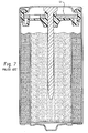
Fig. 3 is a longitudinal cross-sectional view of an electrochemical cell of this invention including the seal member shown inFig. 1 ; -
Fig. 4 is a top view of a vented seal member useful in a cell of this invention; -
Fig. 5 is a cross-sectional view of a vented seal member useful in a cell of this invention; -
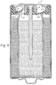
Fig. 6 is a longitudinal cross-sectional view of an electrochemical cell of this invention including the vented seal member shown inFig. 5 ; and -
Fig. 7 is an example of an electrochemical cell which is known in the prior art and includes a vent assembly with a support member. - Referring now to the drawings and more particularly to
Fig. 3 , there is shown a cross-sectional view of an assembled electrochemical cell of this invention. Beginning with the exterior of the cell, the cell components are thecontainer 10,first electrode 12 positioned adjacent the interior surface ofcontainer 10,separator 14 contacting theinterior surface 16 offirst electrode 12,second electrode 18 disposed within the cavity defined byseparator 14 andvent assembly 20 secured tocontainer 10.Container 10 has anopen end 22, aclosed end 24 and asidewall 26 therebetween. Theclosed end 24,sidewall 26 and ventassembly 20 define a cavity in which the cell's electrodes are housed. - Shown in
Figs. 1 and 2 is an embodiment ofseal member 28 which has several sections that perform a variety of functions. As shown inFig. 3 , the perimeter ofseal member 28 is defined byupstanding wall 34 which forms an electrically insulating barrier betweencontainer 10 which serves as the current collector forfirst electrode 12, andterminal cover 32 which serves as the external contact forsecond electrode 18. The interior surface ofperimeter wall 34, also referred to herein as the upstanding wall, forms one side of acover reception channel 76 inseal member 28 into which therollback edge 36 ofcover 32 is inserted. Located adjacent the interior surface ofrollback edge 36 is buttresswall 38 which extends abovediaphragm region 40. The function of buttresswall 38 is to oppose the force exerted ondiaphragm region 40 when the internal generation of gas increases pressure within the cell. In a preferred embodiment,diaphragm region 40 includes anelbow 42 which joins two annular sections ofdiaphragm 40 at an obtuse angle. By configuring the diaphragm so that it is bowed toward the interior of the cell, the pressure exerted on the diaphragm by the buildup of a gas within the cell results in the diaphragm being compressed. When the cell's internal pressure exceeds a predetermined value, the diaphragm inverts and tears atvent line 44 which is a groove in the interior surface of aseal member 28.Vent line 44 is aligned with the outer circumferential surface ofcompression bushing 46, so thatcompression bushing 46 facilitates tearing of the diaphragm atvent line 44. - When diaphragm 40 responds to an excessive increase in internal pressure by inverting and tearing at
vent line 44,diaphragm 40 forms avent flap 48, seeFigs. 5 and6 , with adistal end 50 and aproximate end 52.Vent flap 48 is specifically designed to rotate towardterminal cover 32 so that anopening 78 is created inseal member 28. Pressurized gas within the cell escapes to the environment beyond the cell by passing through the vented opening in the seal member and then through opening 54 interminal cover 32.Vent flap 48 is made to rotate aroundhinge area 56, which is located at theproximate end 52 ofvent flap 48. In a preferred embodiment, hingearea 56 forms an arc that is concentric with thecentral opening 30 inseal member 28. -
Hinge 56 is the arc shaped line in the seal member about which the vent flap rotates when the seal is ruptured. The hinge coincides with at least a portion offirst edge 64 ofdiaphragm 40. Preferably, the hinge forms an arc or a circle that is concentric with the vent assembly's longitudinal axis. Abutting and defining another edge ofdiaphragm 40 issecond edge 66.First edge 64 andsecond edge 66 are concentric with one another and the vent assembly's longitudinal axis. -
Second edge 66 comprises a grooved section and a nongrooved section. The grooved section defines the location ofvent 44. The nongrooved section forms a nonventable interface between a portion ofdiaphragm 40 andhub 70. The nonventable interface forms anchor 82. The function ofanchor 82 is to securevent flap 48 to bothdiaphragm region 40 andhub 70, thereby ensuring thatvent flap 48 does not contactterminal cover 32 and form a 360° seal against the interior surface of the terminal cover when the cell's internal pressure causesseal member 28 to rupture atvent line 44. The arc formed byvent line 44 should be at least 180°, more preferably approximately 220° and most preferably not more than 250°. The portion ofdiaphragm 40 that abutshub 70 and does not includevent line 44 forms ananchor 82. The arc formed byanchor 82 should be at least 30°, more preferably approximately 100° and most preferably less than 180°. Upon activation of the vent, opening 78 is formed by tearing the diaphragm atvent line 44.Opening 78 may extend from one end ofvent line 44 to the other end ofvent line 44 providedopening 78 does not extend into the nongrooved section ofsecond edge 66. Alternatively, opening 78 may extend around a portion ofvent line 44 as shown inFig. 4 . The size ofopening 78 is not critical provided it is large enough for the gas within the cell to rapidly escape when the cell vents. The arc ofanchor 82 and the arc ofvent line 44 form a complete circle. - Relative to the elevation of the vent assembly's
longitudinal axis 58, the elevations ofhinge 56,terminal cover 32 and ventline 44 inseal member 28 are critical to preventing the resealing ofvent flap 48 against the interior surface ofcover 32. If thedistal end 50 ofvent flap 48 is allowed to contactcover 32 and the cell continues to generate gas after the diaphragm has ruptured, as would occur when a cell has been inserted backwards in a multicell device and is subsequently charged by the other cells, then the flap is forcefully pressed againstcover 32 thereby blocking further release of gas through the seal member and cover. If the internal pressure exceeds the container's ability to remain crimped over the perimeter of the seal member, then the vent assembly may be rapidly expelled from the container. Some of the cell's other components, such as electrolyte and portions of the anode, may also be forcefully thrown from the container. - To prevent resealing of a vented seal member, the elevation of the hinge must be closer to the elevation of the vent than to the elevation of the cover's central portion. The elevations of the hinge, vent and cover are determined relative to the
longitudinal axis 58 ofvent assembly 20. As shown inFig. 3 , thelongitudinal axis 58 of the vent assembly is concentric with the longitudinal axis ofcontainer 10. For use in this application, the highest elevation within the vent assembly is the surface of the terminal cover's central portion. Any point along the vent assembly's axis that is between the terminal cover and the end ofcurrent collector 30 that contactssecond electrode 18 is considered to be lower than the highest elevation. The elevation of any feature in the vent assembly is determined by connecting a straight line from the feature in question to the vent assembly's longitudinal axis provided the axis and straight line meet at a right angle. When comparing the elevation of any two features in the vent assembly, the feature with its straight line closest to the surface ofterminal cover 32 is considered to be higher in elevation than the other feature. - As shown in
Fig. 3 , the elevations ofcover 32, hinge 56 and vent 44, relative to the longitudinal axis of the vent assembly, correspond to points A, B and C, respectively. In the vent assembly of the present invention, the elevation of hinge 56 (point B) must be closer to the elevation of vent 44 (point C) than to the elevation of the junction ofcollector 30 and the cover's central portion (point A). Preferably, the elevation ofhinge 56 is greater than the elevation ofvent 44. The physical relationships of the cover, hinge and vent are necessary to ensure that thedistal end 50 ofvent flap 48 does not contact and reseal againstcover 32 when excessive pressure within the cell causesseal member 28 to rupture. During the rupturing ofseal member 28,diaphragm 40 rapidly inverts and tears atvent line 44. The portion of the diaphragm located betweenhinge 56 and vent 44 forms thevent flap 48 which is forced to rotate through the vent deflection zone, towardcover 32, by the pressurized gas as it escapes from the cell. As used herein, the vent deflection zone is the space betweendiaphragm 40 andterminal cover 32. InFig. 3 , the vent deflection zone is identified with parallel diagonal lines. To ensure proper operation of the vent assembly, the vent deflection zone should not be obstructed with any objects that would impede movement of the vent flap. For example, the existence of asupport member 62, shown inFig. 7 , would inhibit proper operation of the vent flap. Consequently, in a preferred embodiment, the vent assembly of this invention includes a seal member, a current collector and a single cover that also functions as one of the cell's terminals. - Inwardly disposed from
second edge 66 ishub base 68,hub 70 andcollector 30.Hub base 68 is thicker thandiaphragm 40.Hub 70 abutshub base 68 at a right angle.Hub 70 definescentral opening 30 inseal member 28. -
Seal member 28 is typically made as a single component by injection molding a polymeric material into a cavity and then allowing the part to solidify. Materials from which the seal member may be made include: nylon 6, 6; polypropylene; and impact modified polystyrene as described inUS 6,306,537 . - An optional component of the vent assembly shown in
Figs. 3 and6 is compression brushing 46. The exteriorcircumferential surface 72 of the compression bushing is made to align withvent 44. In vent assemblies that do not include a compression bushing, the vent is made to align with the outside diameter ofhub 70. -
Terminal cover 32 is a generally cup-shaped component made of nickel-plated steel. Theperimeter 36 ofcover 32 is formed by rolling back the edge of the cover upon itself to create a double thickness of material that is approximately perpendicular to thecentral portion 74 ofcover 32. Between the covered central portion and its perimeter, the cover is contoured through a series of bends. The cover'scentral region 74 is recessed relative to the cover's rolled backedge 36. Whencover 32 is inserted into the seal member'scover reception cavity 76 and the vent assembly is crimped into the open end ofcontainer 10, the cover acts like a spring that compresses the seal member'supstanding wall 34 against the interior surface ofcontainer 10. By contouring the cover to possess a spring like characteristic, the vent assembly does not need to include a separate component to force the seal member's perimeter wall against the container. -
First electrode 12 is a mixture of manganese dioxide, graphite and an aqueous solution containing potassium hydroxide. The electrode is formed by disposing a quantity of the mixture into the open ended container and then using a ram to mold the mixture into a solid tubular shape that defines a cavity which is concentric with the sidewall of the container. Alternatively, the cathode may be formed by preforming a plurality of rings from the mixture comprising manganese dioxide and then inserting the rings into the container to form the tubularly shaped first electrode. -
Second electrode 18 is a homogenous mixture of an aqueous alkaline electrolyte, zinc powder, and a gelling agent such as crosslinked polyacrylic acid. The aqueous alkaline electrolyte comprises an alkaline metal hydroxide such as potassium hydroxide, sodium hydroxide, or mixtures thereof. Potassium hydroxide is preferred. The gelling agent suitable for use in a cell of this invention can be a crosslinked polyacrylic acid, such as Carbopol 940®, which is available from Noveon, Inc., Cleveland, Ohio, USA. Carboxymethylcellulose, polyacrylamide and sodium polyacrylate are examples of other gelling agents that are suitable for use in an alkaline electrolyte solution. The zinc powder may be pure zinc or an alloy comprising an appropriate amount of one or more of the metals selected from the group consisting of indium, lead, bismuth, lithium, calcium and aluminum. A suitable anode mixture contains 67 weight percent zinc powder, 0.50 weight percent gelling agent and 32.5 weight percent alkaline electrolyte having 40 weight percent potassium hydroxide. The quantity of zinc can range from 63 percent by weight to 70 percent by weight of the anode. Other components such as gassing inhibitors, organic or inorganic anticorrosive agents, binders or surfactants may be optionally added to the ingredients listed above. Examples of gassing inhibitors or anticorrosive agents can include indium salts (such as indium hydroxide), perfluoroalkyl ammonium salts, alkali metal sulfides, etc. Examples of surfactants can include polyethylene oxide, polyethylene alkylethers, perfluoroalkyl compounds, and the like. - The second electrode may be manufactured by combining the ingredients described above into a ribbon blender or drum mixer and then working the mixture into a wet slurry.
- Electrolyte suitable for use in a cell of this invention is a "thirty-seven percent by weight aqueous solution of potassium hydroxide. The electrolyte may be incorporated into the cell by disposing a quantity of the fluid electrolyte into the cavity defined by the first electrode. The electrolyte may also be introduced into the cell by allowing the gelling medium to absorb an aqueous solution of potassium hydroxide during the process used to manufacture the second electrode. The method used to incorporate electrolyte into the cell is not critical provided the electrolyte is in contact with the
first electrode 12,second electrode 18 andseparator 14. - During the cell assembly process, a quantity of an aqueous potassium hydroxide solution is incorporated into the cell. The solution serves as the cell's electrolyte. The electrolyte may be incorporated into the cell by allowing the gelling agent in the second electrode to absorb the electrolyte during the electrode manufacturing process which occurs prior to inserting the second electrode into the coiled separator. In addition, a quantity of electrolyte may be dispensed into the partially completed cell any time after the first electrode has been inserted into the container and prior to closing the cell.
-
Separator 14 may be made from nonwoven fibers. One of the separator's functions is to provide a barrier at the interface of the first and second electrodes. The barrier must be electrically insulating and ionically permeable.
Claims (11)
- An electrochemical cell, comprising:(a) an open ended container (10), said container (10) comprises a first electrode (12) in contact with said container (10), a separator (14) in contact with said first electrode (12), a second electrode (18) in contact with said separator (14) and electrolyte in contact with said electrodes (12, 18) and said separator (14); and(b) a vent assembly (20), having a longitudinal axis (58), is concentrically aligned with and secured to the open end (22) of said container (10), said vent assembly (20) comprises:characterized in that said second edge (66) of said thin diaphragm region (40) comprises a grooved section and a nongrooved section, said grooved section defining the location of said vent and said nongrooved section defining an anchor (82) which secures said diaphragm region (40) to said hub (70), and wherein said groove is arc shaped and concentrically aligned with the central opening in said seal member (28).i) an electrically conductive cup shaped cover (32) having a recessed central region (74);ii) a disc shaped rupturable seal member (28) made of a polymeric material and contacting said cover (32), said seal member (28) comprises an upstanding wall (34) defining the perimeter of the seal member (28), and a thin rupturable diaphragm region (40) having a first edge (64), a second edge (66) and located between the seal member's upstanding perimeter wall (34) and a centrally located hub (70) which defines an opening through said seal member (28), said seal member (28) comprises a hinge (56) located adjacent a first edge (64) of the thin diaphragm region (40) and a vent located adjacent a second edge (66) of the thin diaphragm region (40), said hinge's elevation, relative to the longitudinal axis (58) of the vent assembly (20), is closer to the elevation of the vent than to the elevation of the cover's central region (74);iii) an electrically conductive current collector extends through the opening in said seal member (28) and contacts said second electrode (18),
- The electrochemical cell of claim 1, wherein said nongrooved section forms at least a 30° arc.
- The electrochemical cell of claim 1, wherein said nongrooved section forms approximately a 100° arc.
- The electrochemical cell of claim 1, wherein said nongrooved section forms less than a 180° arc.
- The electrochemical cell of claim 1 wherein said grooved section forms an arc greater than 180°.
- The electrochemical cell of claim 1 wherein said grooved section forms an arc greater than 220°.
- The electrochemical cell of claim 1 wherein said grooved section forms an arc greater than 250°.
- The electrochemical cell of claim 1 wherein said hinge's elevation is between the elevation of the vent and the elevation of the cover's central region (74).
- The electrochemical cell of claim 1 wherein said hinge (56) is arc shaped and concentrically aligned with the central opening in said seal member (28).
- The electrochemical cell of any of claims 1 to 9,
characterized in that said seal member (28) comprises a buttress wall (38) abutting said diaphragm region (40) and said cover (32) when said cell is pressurized, said buttress wall (38) positioned to resist the compressive force exerted on said diaphragm by an increase in the cell's internal pressure. - The electrochemical cell of any of claims 1 to 10 wherein said polymeric material is selected from the group consisting of nylon, polypropylene and impact modified polystyrenes.
Applications Claiming Priority (3)
| Application Number | Priority Date | Filing Date | Title |
|---|---|---|---|
| US229406 | 2002-08-28 | ||
| US10/229,406 US20040043286A1 (en) | 2002-08-28 | 2002-08-28 | Seal for an electrochemical cell |
| PCT/US2003/026722 WO2004021470A2 (en) | 2002-08-28 | 2003-08-27 | Seal for an electrochemical cell |
Publications (2)
| Publication Number | Publication Date |
|---|---|
| EP1532700A2 EP1532700A2 (en) | 2005-05-25 |
| EP1532700B1 true EP1532700B1 (en) | 2008-12-17 |
Family
ID=31976212
Family Applications (1)
| Application Number | Title | Priority Date | Filing Date |
|---|---|---|---|
| EP03791795A Expired - Lifetime EP1532700B1 (en) | 2002-08-28 | 2003-08-27 | Seal for an electrochemical cell |
Country Status (8)
| Country | Link |
|---|---|
| US (3) | US20040043286A1 (en) |
| EP (1) | EP1532700B1 (en) |
| JP (1) | JP5009499B2 (en) |
| CN (1) | CN100353587C (en) |
| AT (1) | ATE418164T1 (en) |
| AU (1) | AU2003265699A1 (en) |
| DE (1) | DE60325378D1 (en) |
| WO (1) | WO2004021470A2 (en) |
Families Citing this family (13)
| Publication number | Priority date | Publication date | Assignee | Title |
|---|---|---|---|---|
| JP2007048730A (en) * | 2005-07-15 | 2007-02-22 | Matsushita Electric Ind Co Ltd | Alkaline battery |
| ES2275419B1 (en) * | 2005-07-27 | 2008-04-16 | Celaya Emparanza Y Galdos, S.A. Cegasa | "SAFETY DEVICE IN STAIN CLOSURES OF ELECTROCHEMICAL BATTERIES". |
| US20080166626A1 (en) * | 2007-01-05 | 2008-07-10 | Yoppolo Robert A | End cap seal assembly for an electrochemical cell |
| CN102388482B (en) * | 2009-04-09 | 2013-08-28 | 丰田自动车株式会社 | Batteries, vehicles and devices using batteries |
| JP5679181B2 (en) * | 2010-02-22 | 2015-03-04 | Fdkエナジー株式会社 | Gasket for cylindrical battery, cylindrical battery |
| US9871235B2 (en) * | 2011-11-16 | 2018-01-16 | Johnson Controls Advanced Power Solutions Gmbh | Pressure relief element, pressure relief device and battery |
| WO2015038643A1 (en) * | 2013-09-10 | 2015-03-19 | Encell Technology, Inc. | Gas channeling separator inlays for alkaline batteries |
| US10270137B1 (en) | 2014-04-04 | 2019-04-23 | Olaeris, Inc. | Battery status and failure detector |
| CN107112473B (en) * | 2014-10-17 | 2021-02-26 | 金山电池国际有限公司 | Battery with a battery cell |
| JP6986346B2 (en) * | 2016-12-19 | 2021-12-22 | Fdk株式会社 | Cylindrical alkaline battery |
| US12347878B2 (en) * | 2019-12-18 | 2025-07-01 | Panasonic Energy Co., Ltd. | Cylindrical battery |
| KR102888309B1 (en) * | 2020-05-29 | 2025-11-18 | 주식회사 엘지에너지솔루션 | Secondary battery and manufacturing method of the same |
| CN114883757A (en) * | 2022-05-31 | 2022-08-09 | 远景动力技术(江苏)有限公司 | Cylindrical battery and electronic equipment |
Family Cites Families (15)
| Publication number | Priority date | Publication date | Assignee | Title |
|---|---|---|---|---|
| DE1254726B (en) * | 1962-06-01 | 1967-11-23 | Varta Pertrix Union Ges Mit Be | Galvanic element provided with a degassing valve |
| JP2825868B2 (en) * | 1989-08-31 | 1998-11-18 | 日立マクセル株式会社 | Cylindrical alkaline battery |
| US5227261A (en) * | 1991-10-15 | 1993-07-13 | Eveready Battery Company, Inc. | Cylindrical electrochemical cells with a diaphragm seal |
| US5422201A (en) * | 1993-08-04 | 1995-06-06 | Eveready Battery Company, Inc. | Current collector assembly for an electrochemical cell |
| JP3248332B2 (en) * | 1994-02-25 | 2002-01-21 | 松下電器産業株式会社 | Alkaline battery |
| JPH09245758A (en) * | 1996-03-08 | 1997-09-19 | Sony Corp | AA alkaline battery |
| US5925478A (en) * | 1997-06-25 | 1999-07-20 | Eveready Battery Company, Inc. | V-shaped gasket for galvanic cells |
| JP3948120B2 (en) * | 1998-06-15 | 2007-07-25 | ソニー株式会社 | Gasket, gasket molding method, and cylindrical alkaline battery using the gasket |
| US6306537B2 (en) | 1998-12-29 | 2001-10-23 | Eveready Battery Company, Inc. | Impact modified polystyrene seals for galvanic cells |
| US6270918B1 (en) | 1999-02-08 | 2001-08-07 | Eveready Battery Company, Inc. | Low profile ventable seal for an electrochemical cell |
| US6270919B1 (en) * | 1999-04-27 | 2001-08-07 | Eveready Battery Company, Inc. | Electrochemical cell having low profile seal assembly with anti-resealing vent |
| US6312850B1 (en) * | 1999-09-14 | 2001-11-06 | Eveready Battery Company, Inc. | Current collector and seal assembly for electrochemical cell |
| US6291100B1 (en) * | 1999-09-15 | 2001-09-18 | Irma America, Inc. | Electrode composition comprising doped tungsten oxides and electrochemical cell comprising same |
| US6620543B2 (en) * | 2001-08-09 | 2003-09-16 | Eveready Battery Company, Inc. | Electrochemical cell having can vent and cover terminal |
| JP4186468B2 (en) * | 2002-01-21 | 2008-11-26 | Fdk株式会社 | Sealing gasket for alkaline batteries |
-
2002
- 2002-08-28 US US10/229,406 patent/US20040043286A1/en not_active Abandoned
-
2003
- 2003-08-27 AT AT03791795T patent/ATE418164T1/en not_active IP Right Cessation
- 2003-08-27 EP EP03791795A patent/EP1532700B1/en not_active Expired - Lifetime
- 2003-08-27 DE DE60325378T patent/DE60325378D1/en not_active Expired - Lifetime
- 2003-08-27 CN CNB038205378A patent/CN100353587C/en not_active Expired - Lifetime
- 2003-08-27 WO PCT/US2003/026722 patent/WO2004021470A2/en not_active Ceased
- 2003-08-27 JP JP2004531492A patent/JP5009499B2/en not_active Expired - Lifetime
- 2003-08-27 AU AU2003265699A patent/AU2003265699A1/en not_active Abandoned
-
2004
- 2004-10-13 US US10/964,039 patent/US7527891B2/en not_active Expired - Lifetime
-
2009
- 2009-03-26 US US12/411,712 patent/US7704632B2/en not_active Expired - Lifetime
Also Published As
| Publication number | Publication date |
|---|---|
| US20040043286A1 (en) | 2004-03-04 |
| WO2004021470A2 (en) | 2004-03-11 |
| EP1532700A2 (en) | 2005-05-25 |
| US20090181287A1 (en) | 2009-07-16 |
| JP2005536855A (en) | 2005-12-02 |
| US7704632B2 (en) | 2010-04-27 |
| US7527891B2 (en) | 2009-05-05 |
| CN100353587C (en) | 2007-12-05 |
| US20050084744A1 (en) | 2005-04-21 |
| WO2004021470A3 (en) | 2004-12-02 |
| AU2003265699A8 (en) | 2004-03-19 |
| ATE418164T1 (en) | 2009-01-15 |
| AU2003265699A1 (en) | 2004-03-19 |
| JP5009499B2 (en) | 2012-08-22 |
| CN1679180A (en) | 2005-10-05 |
| DE60325378D1 (en) | 2009-01-29 |
Similar Documents
| Publication | Publication Date | Title |
|---|---|---|
| US7704632B2 (en) | Electrochemical cell having a vent assembly with a rupturable seal member | |
| US7491464B2 (en) | Alkaline cell with flat housing | |
| EP1456894B1 (en) | Electrochemical cell having venting current collector and seal assembly | |
| US6861174B2 (en) | Electrochemical cell with low volume cover assembly | |
| US6733917B1 (en) | Seal for pressurized container with a rupturable seal | |
| US7294429B2 (en) | Alkaline cell with flat housing | |
| EP1476910B1 (en) | Seal for an electrochemical cell | |
| US7351495B2 (en) | Method of adding electrolyte to a gap between the cathode and separator of an alkaline cell | |
| EP1595298B1 (en) | Electrochemical cell with low volume cover assembly | |
| EP1716607A2 (en) | Alkaline cell with flat housing | |
| HK1069483B (en) | Electrochemical cell having venting current collector and seal assembly | |
| HK1084241B (en) | Electrochemical cell with low volume cover assembly |
Legal Events
| Date | Code | Title | Description |
|---|---|---|---|
| PUAI | Public reference made under article 153(3) epc to a published international application that has entered the european phase |
Free format text: ORIGINAL CODE: 0009012 |
|
| 17P | Request for examination filed |
Effective date: 20050202 |
|
| AK | Designated contracting states |
Kind code of ref document: A2 Designated state(s): AT BE BG CH CY CZ DE DK EE ES FI FR GB GR HU IE IT LI LU MC NL PT RO SE SI SK TR |
|
| AX | Request for extension of the european patent |
Extension state: AL LT LV MK |
|
| DAX | Request for extension of the european patent (deleted) | ||
| RIN1 | Information on inventor provided before grant (corrected) |
Inventor name: JANMEY, ROBERT, M. |
|
| 17Q | First examination report despatched |
Effective date: 20071017 |
|
| GRAP | Despatch of communication of intention to grant a patent |
Free format text: ORIGINAL CODE: EPIDOSNIGR1 |
|
| GRAS | Grant fee paid |
Free format text: ORIGINAL CODE: EPIDOSNIGR3 |
|
| GRAA | (expected) grant |
Free format text: ORIGINAL CODE: 0009210 |
|
| AK | Designated contracting states |
Kind code of ref document: B1 Designated state(s): AT BE BG CH CY CZ DE DK EE ES FI FR GB GR HU IE IT LI LU MC NL PT RO SE SI SK TR |
|
| REG | Reference to a national code |
Ref country code: GB Ref legal event code: FG4D |
|
| REG | Reference to a national code |
Ref country code: CH Ref legal event code: EP |
|
| REG | Reference to a national code |
Ref country code: IE Ref legal event code: FG4D |
|
| REF | Corresponds to: |
Ref document number: 60325378 Country of ref document: DE Date of ref document: 20090129 Kind code of ref document: P |
|
| PG25 | Lapsed in a contracting state [announced via postgrant information from national office to epo] |
Ref country code: SI Free format text: LAPSE BECAUSE OF FAILURE TO SUBMIT A TRANSLATION OF THE DESCRIPTION OR TO PAY THE FEE WITHIN THE PRESCRIBED TIME-LIMIT Effective date: 20081217 Ref country code: FI Free format text: LAPSE BECAUSE OF FAILURE TO SUBMIT A TRANSLATION OF THE DESCRIPTION OR TO PAY THE FEE WITHIN THE PRESCRIBED TIME-LIMIT Effective date: 20081217 Ref country code: NL Free format text: LAPSE BECAUSE OF FAILURE TO SUBMIT A TRANSLATION OF THE DESCRIPTION OR TO PAY THE FEE WITHIN THE PRESCRIBED TIME-LIMIT Effective date: 20081217 |
|
| NLV1 | Nl: lapsed or annulled due to failure to fulfill the requirements of art. 29p and 29m of the patents act | ||
| PG25 | Lapsed in a contracting state [announced via postgrant information from national office to epo] |
Ref country code: ES Free format text: LAPSE BECAUSE OF FAILURE TO SUBMIT A TRANSLATION OF THE DESCRIPTION OR TO PAY THE FEE WITHIN THE PRESCRIBED TIME-LIMIT Effective date: 20090328 Ref country code: RO Free format text: LAPSE BECAUSE OF FAILURE TO SUBMIT A TRANSLATION OF THE DESCRIPTION OR TO PAY THE FEE WITHIN THE PRESCRIBED TIME-LIMIT Effective date: 20081217 Ref country code: EE Free format text: LAPSE BECAUSE OF FAILURE TO SUBMIT A TRANSLATION OF THE DESCRIPTION OR TO PAY THE FEE WITHIN THE PRESCRIBED TIME-LIMIT Effective date: 20081217 Ref country code: BG Free format text: LAPSE BECAUSE OF FAILURE TO SUBMIT A TRANSLATION OF THE DESCRIPTION OR TO PAY THE FEE WITHIN THE PRESCRIBED TIME-LIMIT Effective date: 20090317 |
|
| PG25 | Lapsed in a contracting state [announced via postgrant information from national office to epo] |
Ref country code: SE Free format text: LAPSE BECAUSE OF FAILURE TO SUBMIT A TRANSLATION OF THE DESCRIPTION OR TO PAY THE FEE WITHIN THE PRESCRIBED TIME-LIMIT Effective date: 20090317 Ref country code: PT Free format text: LAPSE BECAUSE OF FAILURE TO SUBMIT A TRANSLATION OF THE DESCRIPTION OR TO PAY THE FEE WITHIN THE PRESCRIBED TIME-LIMIT Effective date: 20090518 Ref country code: CZ Free format text: LAPSE BECAUSE OF FAILURE TO SUBMIT A TRANSLATION OF THE DESCRIPTION OR TO PAY THE FEE WITHIN THE PRESCRIBED TIME-LIMIT Effective date: 20081217 Ref country code: AT Free format text: LAPSE BECAUSE OF FAILURE TO SUBMIT A TRANSLATION OF THE DESCRIPTION OR TO PAY THE FEE WITHIN THE PRESCRIBED TIME-LIMIT Effective date: 20081217 |
|
| PG25 | Lapsed in a contracting state [announced via postgrant information from national office to epo] |
Ref country code: SK Free format text: LAPSE BECAUSE OF FAILURE TO SUBMIT A TRANSLATION OF THE DESCRIPTION OR TO PAY THE FEE WITHIN THE PRESCRIBED TIME-LIMIT Effective date: 20081217 |
|
| PLBE | No opposition filed within time limit |
Free format text: ORIGINAL CODE: 0009261 |
|
| STAA | Information on the status of an ep patent application or granted ep patent |
Free format text: STATUS: NO OPPOSITION FILED WITHIN TIME LIMIT |
|
| PG25 | Lapsed in a contracting state [announced via postgrant information from national office to epo] |
Ref country code: DK Free format text: LAPSE BECAUSE OF FAILURE TO SUBMIT A TRANSLATION OF THE DESCRIPTION OR TO PAY THE FEE WITHIN THE PRESCRIBED TIME-LIMIT Effective date: 20081217 |
|
| 26N | No opposition filed |
Effective date: 20090918 |
|
| PG25 | Lapsed in a contracting state [announced via postgrant information from national office to epo] |
Ref country code: MC Free format text: LAPSE BECAUSE OF NON-PAYMENT OF DUE FEES Effective date: 20090831 |
|
| REG | Reference to a national code |
Ref country code: CH Ref legal event code: PL |
|
| PG25 | Lapsed in a contracting state [announced via postgrant information from national office to epo] |
Ref country code: CH Free format text: LAPSE BECAUSE OF NON-PAYMENT OF DUE FEES Effective date: 20090831 Ref country code: LI Free format text: LAPSE BECAUSE OF NON-PAYMENT OF DUE FEES Effective date: 20090831 |
|
| REG | Reference to a national code |
Ref country code: FR Ref legal event code: ST Effective date: 20100430 |
|
| PG25 | Lapsed in a contracting state [announced via postgrant information from national office to epo] |
Ref country code: FR Free format text: LAPSE BECAUSE OF NON-PAYMENT OF DUE FEES Effective date: 20090831 Ref country code: IE Free format text: LAPSE BECAUSE OF NON-PAYMENT OF DUE FEES Effective date: 20090827 |
|
| PG25 | Lapsed in a contracting state [announced via postgrant information from national office to epo] |
Ref country code: GR Free format text: LAPSE BECAUSE OF FAILURE TO SUBMIT A TRANSLATION OF THE DESCRIPTION OR TO PAY THE FEE WITHIN THE PRESCRIBED TIME-LIMIT Effective date: 20090318 |
|
| PG25 | Lapsed in a contracting state [announced via postgrant information from national office to epo] |
Ref country code: IT Free format text: LAPSE BECAUSE OF FAILURE TO SUBMIT A TRANSLATION OF THE DESCRIPTION OR TO PAY THE FEE WITHIN THE PRESCRIBED TIME-LIMIT Effective date: 20081217 |
|
| PG25 | Lapsed in a contracting state [announced via postgrant information from national office to epo] |
Ref country code: LU Free format text: LAPSE BECAUSE OF NON-PAYMENT OF DUE FEES Effective date: 20090827 |
|
| PG25 | Lapsed in a contracting state [announced via postgrant information from national office to epo] |
Ref country code: HU Free format text: LAPSE BECAUSE OF FAILURE TO SUBMIT A TRANSLATION OF THE DESCRIPTION OR TO PAY THE FEE WITHIN THE PRESCRIBED TIME-LIMIT Effective date: 20090618 |
|
| PG25 | Lapsed in a contracting state [announced via postgrant information from national office to epo] |
Ref country code: TR Free format text: LAPSE BECAUSE OF FAILURE TO SUBMIT A TRANSLATION OF THE DESCRIPTION OR TO PAY THE FEE WITHIN THE PRESCRIBED TIME-LIMIT Effective date: 20081217 |
|
| PG25 | Lapsed in a contracting state [announced via postgrant information from national office to epo] |
Ref country code: CY Free format text: LAPSE BECAUSE OF FAILURE TO SUBMIT A TRANSLATION OF THE DESCRIPTION OR TO PAY THE FEE WITHIN THE PRESCRIBED TIME-LIMIT Effective date: 20081217 |
|
| REG | Reference to a national code |
Ref country code: DE Ref legal event code: R082 Ref document number: 60325378 Country of ref document: DE Representative=s name: VON KREISLER SELTING WERNER - PARTNERSCHAFT VO, DE Ref country code: DE Ref legal event code: R081 Ref document number: 60325378 Country of ref document: DE Owner name: ENERGIZER BRANDS, LLC (N.D.GES.D. STAATES DELA, US Free format text: FORMER OWNER: EVEREADY BATTERY CO., INC., WESTLAKE, OHIO, US Ref country code: DE Ref legal event code: R082 Ref document number: 60325378 Country of ref document: DE Representative=s name: DOMPATENT VON KREISLER SELTING WERNER - PARTNE, DE |
|
| REG | Reference to a national code |
Ref country code: GB Ref legal event code: 732E Free format text: REGISTERED BETWEEN 20161013 AND 20161019 |
|
| REG | Reference to a national code |
Ref country code: DE Ref legal event code: R079 Ref document number: 60325378 Country of ref document: DE Free format text: PREVIOUS MAIN CLASS: H01M0002120000 Ipc: H01M0050300000 |
|
| PGFP | Annual fee paid to national office [announced via postgrant information from national office to epo] |
Ref country code: GB Payment date: 20220707 Year of fee payment: 20 Ref country code: DE Payment date: 20220608 Year of fee payment: 20 |
|
| PGFP | Annual fee paid to national office [announced via postgrant information from national office to epo] |
Ref country code: BE Payment date: 20220718 Year of fee payment: 20 |
|
| P01 | Opt-out of the competence of the unified patent court (upc) registered |
Effective date: 20230526 |
|
| P02 | Opt-out of the competence of the unified patent court (upc) changed |
Effective date: 20230703 |
|
| REG | Reference to a national code |
Ref country code: DE Ref legal event code: R071 Ref document number: 60325378 Country of ref document: DE |
|
| REG | Reference to a national code |
Ref country code: GB Ref legal event code: PE20 Expiry date: 20230826 |
|
| REG | Reference to a national code |
Ref country code: BE Ref legal event code: MK Effective date: 20230827 |
|
| PG25 | Lapsed in a contracting state [announced via postgrant information from national office to epo] |
Ref country code: GB Free format text: LAPSE BECAUSE OF EXPIRATION OF PROTECTION Effective date: 20230826 |