EP1531604A2 - Verschiebbare Gelenkvorrichtung für drehbare und verschiebbare Mobilgeräte - Google Patents
Verschiebbare Gelenkvorrichtung für drehbare und verschiebbare Mobilgeräte Download PDFInfo
- Publication number
- EP1531604A2 EP1531604A2 EP04026954A EP04026954A EP1531604A2 EP 1531604 A2 EP1531604 A2 EP 1531604A2 EP 04026954 A EP04026954 A EP 04026954A EP 04026954 A EP04026954 A EP 04026954A EP 1531604 A2 EP1531604 A2 EP 1531604A2
- Authority
- EP
- European Patent Office
- Prior art keywords
- hinge frame
- hinge
- plate
- housing
- slide
- Prior art date
- Legal status (The legal status is an assumption and is not a legal conclusion. Google has not performed a legal analysis and makes no representation as to the accuracy of the status listed.)
- Granted
Links
Images


Classifications
-
- H—ELECTRICITY
- H04—ELECTRIC COMMUNICATION TECHNIQUE
- H04M—TELEPHONIC COMMUNICATION
- H04M1/00—Substation equipment, e.g. for use by subscribers
- H04M1/02—Constructional features of telephone sets
- H04M1/0202—Portable telephone sets, e.g. cordless phones, mobile phones or bar type handsets
- H04M1/0206—Portable telephones comprising a plurality of mechanically joined movable body parts, e.g. hinged housings
- H04M1/0208—Portable telephones comprising a plurality of mechanically joined movable body parts, e.g. hinged housings characterized by the relative motions of the body parts
- H04M1/0235—Slidable or telescopic telephones, i.e. with a relative translation movement of the body parts; Telephones using a combination of translation and other relative motions of the body parts
- H04M1/0237—Sliding mechanism with one degree of freedom
-
- H—ELECTRICITY
- H04—ELECTRIC COMMUNICATION TECHNIQUE
- H04M—TELEPHONIC COMMUNICATION
- H04M1/00—Substation equipment, e.g. for use by subscribers
- H04M1/02—Constructional features of telephone sets
- H04M1/0202—Portable telephone sets, e.g. cordless phones, mobile phones or bar type handsets
- H04M1/0206—Portable telephones comprising a plurality of mechanically joined movable body parts, e.g. hinged housings
- H04M1/0208—Portable telephones comprising a plurality of mechanically joined movable body parts, e.g. hinged housings characterized by the relative motions of the body parts
- H04M1/0225—Rotatable telephones, i.e. the body parts pivoting to an open position around an axis perpendicular to the plane they define in closed position
- H04M1/0227—Rotatable in one plane, i.e. using a one degree of freedom hinge
-
- H—ELECTRICITY
- H04—ELECTRIC COMMUNICATION TECHNIQUE
- H04M—TELEPHONIC COMMUNICATION
- H04M1/00—Substation equipment, e.g. for use by subscribers
- H04M1/02—Constructional features of telephone sets
- H04M1/0202—Portable telephone sets, e.g. cordless phones, mobile phones or bar type handsets
- H04M1/0206—Portable telephones comprising a plurality of mechanically joined movable body parts, e.g. hinged housings
- H04M1/0208—Portable telephones comprising a plurality of mechanically joined movable body parts, e.g. hinged housings characterized by the relative motions of the body parts
- H04M1/0225—Rotatable telephones, i.e. the body parts pivoting to an open position around an axis perpendicular to the plane they define in closed position
- H04M1/0233—Including a rotatable display body part
Definitions
- the present invention relates generally to a sliding/hinge apparatus for sliding/rotating type mobile terminals. More particularly, the present invention relates to a sliding hinge apparatus which can be slid and rotated from a body housing of the sliding/rotating type mobile terminal.
- portable communication devices describes devices that are portable and enable owners of the devices to perform wireless communications.
- portable communication devices include hand-held PCs (HHP), CT-2 cellular phones, digital phones, PCS phones, and personal digital assistants (PDAs).
- HHP hand-held PCs
- CT-2 CT-2 cellular phones
- digital phones digital phones
- PCS phones personal digital assistants
- PDAs personal digital assistants
- the portable communication devices can be classified into several types of portable wireless terminals.
- portable wireless terminals can be basically classified as a bar-type wireless terminal, a flip-type wireless terminal, and a folder-type wireless terminal.
- the bar-type wireless terminal has a bar-type single housing
- the flip-type wireless terminal comprises a bar-type housing and a flip part rotatably attached to the housing by means of a hinge apparatus
- the folder-type wireless terminal comprises a bar-type housing and a folder part rotatably attached to the housing by means of a hinge apparatus.
- the portable wireless terminals can also be classified as a necklace-type wireless terminal and a wrist-type wireless terminal.
- the necklace-type wireless terminal is worn on the neck of a user by means of a string or chain
- the wrist-type wireless terminal is worn on the wrist of the user by means of a wrist band.
- the portable wireless terminals can be further classified as a rotating-type wireless terminal and a sliding-type wireless terminal.
- the rotating-type wireless terminal is characterized in that the two housings are rotatably connected to each other while the housings are continuously opposite to each other.
- the rotating-type wireless terminal is opened or closed by the rotation of the two housings in such a manner that the housings are rotated apart from or close to each other.
- the sliding-type wireless terminal is characterized in that one of two housings is longitudinally slid relative to the other of the housings.
- the sliding-type wireless terminal is opened or closed by the sliding movement of one of the housings in such a manner that the housings are apart from or close to each other.
- Each conventional portable wireless terminal is indispensably provided with an antenna unit, data input/output units, and data transmitting/receiving units.
- the data input unit usually comprises a keypad with which data is input by means of depressing buttons via the user's fingers or a stylus. Alternatively, there a touch pad or a touch screen can be used.
- the data output unit generally uses an LCD.
- the conventional portable communication device is provided with a camera lens so that a user of the device can talk with another user of the device while looking at each other, or take pictures of desired subjects
- one of the housing pieces i.e., a slide housing
- the other housing i.e., a body housing
- This feature of the sliding-type mobile terminal fully satisfies users' various changeable preferences as compared to the conventional folder-type mobile terminal.
- the slide housing of the sliding-type mobile terminal is slid upward or downward along the body housing of the sliding-type mobile terminal by approximately half of the length of the body housing so that the sliding-type mobile terminal is opened.
- the body housing of the sliding-type mobile terminal is usually provided with a keypad comprising a plurality of keys, which are arranged in a 3 x 4 matrix.
- the slide housing of the sliding-type mobile terminal is usually provided with a liquid crystal display unit.
- the slide housing of the sliding-type mobile terminal can be guided on the body housing of the sliding-type mobile terminal by means of a guiding member.
- a guiding member either the slide housing or the body housing is provided with a guide rib while the other of the slide housing and the body housing is provided with a guide slit, which corresponds to the guide rib.
- the sliding and body housings are provided at the positions where the sliding-type mobile terminal is fully opened and closed with stoppers so that excessive sliding of the slide housing on the body housing is effectively prevented.
- the liquid crystal display unit is formed in the shape of a rectangle, the length of which is large in the longitudinal direction of the terminal, so that the size of the liquid crystal display unit is increased in proportion to the external size of the sliding/rotating type mobile terminal.
- the liquid crystal display unit will be rotated when a wide screen is desired (or necessary) as the liquid crystal display unit extends in the longitudinal direction of the terminal. Consequently, the keypad rotates along with the terminal, with the result that inputting data via the keys is very difficult.
- the display screen is small. As a result, it is inconvenient for a user to watch TV, moving images, and games on the liquid crystal display unit of the terminal.
- the sliding type mobile terminal includes a main body, a sub body, a spring module, a slide guide, and a slide groove.
- the sub body is merely slid upward and downward, not rotated. Consequently, the liquid crystal display unit disposed on the sub body is not used in the form of a wide screen.
- the present invention has been made in view of the above problem, and it is an object of the present invention to provide a sliding hinge apparatus for sliding/rotating type mobile terminals, which can be slid and rotated from a body housing of the sliding/rotating type mobile terminal, whereby the usability of the mobile terminal is improved.
- a sliding/hinge apparatus for sliding/rotating type mobile terminals, each of the terminals comprising a body housing and a slide housing slidably mounted on the body housing, wherein the sliding/hinge apparatus comprises a first hinge frame mounted in the body housing, a second hinge frame disposed on first hinge frame while the second hinge frame is opposite to the first hinge frame so that the slide housing is slid and rotated about a hinge axis, first and second plates slidably attached to the second hinge frame, the first and second plates being fixed to the slide housing and one or more slide bars disposed between the second hinge frame and the first plate.
- the sliding/hinge apparatus further comprises a coupling unit inserted through the center parts of the first and second hinge frames so that the first and second hinge frames are rotatably coupled with each other while being opposite to each other.
- a sliding hinge apparatus for sliding/rotating type mobile terminals, each of the terminals comprising a body housing and a slide housing slidably mounted on the body housing, wherein the sliding/hinge apparatus comprises a first hinge frame mounted in the body housing, a second hinge frame having a cylindrical hinge housing inserted through the first hinge frame while being opposite to the first hinge frame so that the slide housing is slid and rotated about a hinge axis, and first and second plates slidably attached to the second hinge frame, the first and second plates being fixed to the slide housing.
- the sliding/hinge apparatus further comprises one or more slide bars disposed between the second hinge frame and the first plate, a rotary washer provided between the first and second hinge frames so that the second hinge frame is rotated while being opposite to the first hinge frame and a snap ring connected to the lower end of the hinge housing.
- a sliding/hinge apparatus for sliding/rotating type mobile terminals, each of the terminals comprising a body housing and a slide housing slidably mounted on the body housing, wherein the sliding/hinge apparatus comprises a first hinge frame mounted in the body housing, a second hinge frame disposed on the first hinge frame while the second hinge frame is opposite to the first hinge frame so that the slide housing is slid and rotated about a hinge axis, and a first plate slidably and rotatably attached to the second hinge frame; a second plate attached to the first plate, the second plate being fixed to the sliding housing; one or more slide bars disposed between the second hinge frame and the first plate.
- the sliding/hinge apparatus further comprises a guide pin formed at a prescribed position of the first hinge frame and a pin guide hole formed at the first plate, the guide pin being disposed in the pin guide hole such that the guide pin is slid and rotated.
- a sliding/hinge apparatus for sliding/rotating type mobile terminals, each of the terminals comprising a body housing and a slide housing slidably mounted on the body housing, wherein the sliding/hinge apparatus comprises a first hinge frame mounted in the body housing a second hinge frame disposed on the first hinge frame while the second hinge frame is opposite to the first hinge frame so that the slide housing is rotated about a hinge axis, first and second plates attached to the second hinge frame, the first and second plates being provided with slide bars, respectively, so that the slide housing is slid and first and second slide bars attached to both sides of the first plate such that the second plate is slid between the first and second slide bars.
- the sliding/hinge apparatus further comprises a guide pin formed at a prescribed position of the first hinge frame such that the guide pin is guided along a guide formed at the second plate.
- a sliding/hinge apparatus for sliding/rotating type mobile terminals, each of the terminals comprising a body housing and a slide housing slidably mounted on the body housing, wherein the sliding/hinge apparatus comprises a first hinge frame mounted in the body housing, a second hinge frame disposed on the first hinge frame while the second hinge frame is opposite to the first hinge frame so that the slide housing can be rotated about a hinge axis and first and second plates attached to the second hinge frame such that the slide housing can be slid.
- the sliding/hinge apparatus further comprises a guide unit formed at both sides of the first and second plates such that the second plate can be slid, and a stopper pin formed at a prescribed position of the upper surface of the body housing such that the first and second plates can be slid and rotated, and the slid and rotated first and second plates can be stopped by means of the stopper pin.
- the sliding/hinge apparatus 10 for sliding/rotating type mobile terminals according to a first preferred embodiment of the present invention with reference to Figs. 1 to 14.
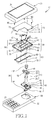
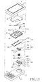
- the sliding/hinge apparatus 10 comprises first and second hinge frames 40 and 50, first and second plates 60 and 70, one or more slide bars 80 and a coupling unit 90.
- the first hinge frame 40 is mounted in a body housing 20 of the sliding/rotating type mobile terminal in such a manner that the first hinge frame 40 is rotatably attached to the second hinge frame 50.
- the first hinge frame 40 is securely fixed to the body housing 20 by means of screws 93.
- the second hinge frame 50 is attached to the first hinge frame 40 while the second hinge frame 50 is opposite to the first hinge frame 40 so that a slide housing 30 of the sliding/rotating type mobile terminal is slid and rotated about a hinge axis A1 (see Fig. 12).
- the first plate 60 is slidably attached to the second hinge frame 50.
- the second plate 70 is attached to the first plate 60 in such a manner that the second plate 70 is fixed to the slide housing 30 by means of screws 93.
- the slide bars 80 are disposed between the second hinge frame 50 and the first plate 60 such that the slide housing 30 is slidably supported by means of the slide bars 80
- the slide bars 80 are fixed to the first plate 60 by means of screws.
- the coupling unit 90 is inserted through the center parts of the first and second hinge frames 40 and 50 so that the first and second hinge frames 40 and 50 are rotatably coupled with each other while being opposite to each other.
- the coupling unit 90 comprises a bush 91 and a snap ring 92.
- the bush 91 is inserted through the center parts of the first and second hinge frames 40 and 50 so that the first and second hinge frames 40 and 50 are rotatably coupled with each other while being opposite to each other.
- the snap ring 92 is connected to the lower end of the bush 91 while being inserted through the first and second hinge frames 40 and 50.
- the first hinge frame 40 (Fig 2) comprises a pair of stoppers 41, a first hinge frame side through-hole 42, ball grooves 43, a pair of rotary stoppers 45, one or more screw engaging parts 44 and a ball guide groove 46.
- the stoppers 41 are provided at the upper ends of the first hinge frame 40 such that clearance of the second hinge frame 50 due to rotation of the second hinge frame 50 is adjusted by means of the stoppers 41.
- the first hinge frame side through-hole 42 is formed through the center part of the first hinge frame 40 so that the bush 91 is inserted through the first hinge frame side through-hole 42.
- the ball grooves 43 are formed around the through-hole 42 while being spaced uniformly apart from each other in the circumferential direction so that a plurality of balls 54 are securely located in the ball grooves 43, respectively.
- the ball guide groove 46 is formed such that the ball grooves 43 are connected to each other by means of the ball guide groove 46.
- the balls 54 are guided along the ball guide groove 46.
- the rotary stoppers 45 are formed at prescribed positions around the ball guide groove 46.
- the rotary stoppers 45 contact the second hinge frame 50 so that the rotation of the slide housing 30 is stopped.
- the screw engaging parts 44 are formed on the first hinge frame 40 so that the screw engaging parts 44 are attached to the inside of the body housing 20 by means of the screws 93 under the condition that the first and second hinge frames 40 and 50 are coupled with each other while being opposite to each other.
- the rotary stoppers 45 are arranged in such a manner that the stoppers 45 are diagonally opposite to each other.
- the second hinge frame 50 (Fig. 2) comprises a second hinge frame side through-hole 51, a cylinder 52, one or more spring holes 53, one or more balls 54, a pair of guide grooves 55 and a stopper protrusion 56.
- the second hinge frame side through-hole 51 is formed through the center part of the second hinge frame 50 so that the bush 91 is inserted through the second hinge frame side through-hole 51.
- the cylinder 52 is formed around the through-hole 51 while being extended downward in the direction of the hinge axis A1 such that the cylinder 52 is opposite to the ball grooves 43 of the first hinge frame 40.
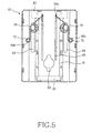
- the spring holes 53 (Fig. 6) are formed while being spaced uniformly apart from each other in the circumferential direction such that the balls 54 and compression springs 57 are mounted in the corresponding spring holes 53.
- the balls 54 are safely placed in the spring holes 53, respectively, such that the balls 54 emerge from the lower ends of the spring holes 53, respectively, by means of an elastic force from the compression springs 57.
- the balls 54 are mounted in the corresponding spring holes 53 in such a manner that the balls 54 are engaged in the ball grooves 43 of the first hinge frame 40, respectively.
- the guide grooves 55 are formed at the upper ends of the second hinge frame 50 such that the guide grooves 55 are slidably attached to the first slide bar 81 (Fig. 4).
- the stopper protrusion 56 is formed at one side of the upper part of the second hinge frame 50.
- the stopper protrusion 56 contacts the second slide bar 82 so that the sliding movement of the slide bars 80 is stopped.
- the first plate 60 (Figs. 1, 5, 6 and 8-10) comprises a plurality of coupling holes 61, one or more screw holes 62, a first plate side through-hole 63, supporting protrusions 64, and a pair of guide holes 65.
- the plurality of coupling holes 61 are formed around the first plate 60 such that coupling protrusions 77 formed at the second plate 70 are fixedly engaged in the coupling holes 61, respectively.
- the screw holes 62 are formed at prescribed positions of the first plate 60 such that the slide bars 80 are fixed by means of the screws 93.
- the first plate side through-hole 63 is formed at a prescribed position of the first plate 60 such that a flexible circuit (not shown) electrically connected to the slide housing 30 can be inserted through the first plate side through-hole 63.
- the supporting protrusions 64 are formed in the longitudinal direction of the first plate 60 such that the slide bars 80 are supported by means of the supporting protrusions 64, respectively.
- the guide holes 65 are formed in the longitudinal direction of the first plate 60 such that ring springs 94, which will be described in greater detail below, are guided by means of the guide holes 65.
- the first plate 60 is provided with a plurality of fixing holes 66, which are formed in the longitudinal direction of the first plate 60 such that protrusions formed at the slide bars 80 are fixedly engaged in the fixing holes 66, respectively.
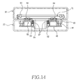
- the second plate 70 (Figs. 1, 13 and 14) comprises: a plurality of coupling protrusions 77, one or more screw holes 72, a pair of pins 73, and a second plate side through-hole 74.
- the coupling protrusions 77 are formed around the second plate 70 such that the coupling protrusions 77 are fixedly engaged in the coupling holes 61 of the first plate 60, respectively.
- a plurality of screws 93 are engaged in the screw holes 72, respectively, so that the second plate 70 is fixed to the sliding housing 30.
- the pins 73 are formed at prescribed positions of the second plate 70 such that the pins 73 are connected to ring springs 94, which will be described in greater detail below, respectively.
- the second plate side through-hole 74 is formed at a prescribed position of the second plate 70 such that a flexible circuit (not shown) electrically connected to the slide housing 30 can be inserted through the second plate side through-hole 74.
- a pair of ring springs 94 for providing an elastic force, by which the slide housing 30 is semi-automatically slid.
- the slide bar 80 (Fig. 1) comprises first slide bars 81, a second slide bar 82, and third slide bars 83.
- the first slide bars 81 are formed in the longitudinal directions of the first and second plates 60 and 70 such that the first slide bars 81 are slid while being engaged in the guide grooves 55 formed at the second hinge frame 50.
- the second slide bar 82 is connected to one end of each of the first slide bars 81 such that the first slide bars 81 are supported by means of the second slide bar 82 and the second slide bar 82 contacts the stopper protrusion 56 of the second hinge frame 50, by which the sliding movement of the slide bar 80 is stopped.
- the third slide bars 83 is connected to the other end of each of the first slide bars 81 such that the first slide bars 81 are supported by means of the third slide bars 83, respectively.
- the sliding type mobile terminal includes a body housing 20, having a keypad 21 comprising a plurality of keys disposed thereon, and a slide housing 30, having a liquid crystal display unit 31 disposed thereon.
- a mounting hole 22 At a prescribed position of the upper part of the body housing 20 is formed a mounting hole 22, in which the first and second hinge frames 40 and 50 are mounted, as shown in Fig. 1.
- the first hinge frame 40 of the sliding/hinge apparatus 10 of the sliding/rotating type mobile terminal is fixed to the body housing 20 by means of screws.
- On the upper part of the first hinge frame 40 is disposed the second hinge frame 50 while the second hinge frame 50 is opposite to the first hinge frame 40 in such a manner that the slide housing 30 is slid and rotated about the hinge axis A1.
- the snap ring is fitted 92 in a fitting groove formed at the lower end of the bush 91.
- the first and second hinge frames 40 and 50 are formed the first and second hinge frame side through-holes 42 and 51, through which the bush 91 is inserted.
- first hinge frame 40 At the upper ends of the first hinge frame 40 are formed a pair of stoppers 41 for controlling clearance of the second hinge frame 50 due to the rotation thereof (Fig. 4). To the upper part of the second hinge frame 50 is attached the first plate 60 in such a manner that the slide housing 30 is slid, as shown in Figs. 3 and 4.
- the first slide bars 81 are slid along the guide grooves 55, respectively, since the pair of first slide bars 81, which are engaged in the pair of guide grooves 55 formed at the upper part of the second hinge frame 50, are disposed between the second hinge frame 50 and the first plate 60.
- the pair of ring springs 94 that are capable of providing an elastic force, by which the slide housing 30 is semi-automatically slid, are mounted in the first and second plates 60 and 70. Consequently, the slide housing 30 is semi-automatically slid by means of the elastic force of the ring springs 94.
- each of the ring springs 94 is inserted through the corresponding guide hole 65 of the first plate 60 so that the end 94a is engaged in the supporting groove 58 formed at the upper part of the second hinge frame 50, and the other end 94b of each of the ring springs 94 is connected to the corresponding pin 73 formed at the second plate 70, so that the ring springs 94 semi-automatically provide the elastic force.
- the first slide bars 81 are formed in the longitudinal direction of the plates, and the first slide bars 81 are connected to each other at one end of each thereof by means of the second slide bar 82.
- the first slide bars 81 are provided at the other end of each thereof with the third slide bars 83, respectively.
- the second hinge frame 50 is provided at one side of the upper part thereof with the stopper protrusion 56, by which the movement of the slide bar is stopped.
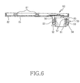
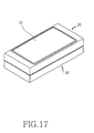
- the slide housing 30 When the slide housing 30 is slid and then rotated as shown in Fig. 12, the slide housing 30 is placed on the body housing 20 in the shape of a "T".
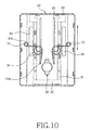
- One or more ball grooves 43 in which the balls 54 are securely located, are formed around the first hinge frame side through-hole 42 while being spaced uniformly apart from each other in the circumferential direction thereof as shown in Fig. 9. Consequently, the balls 54 are securely located in the ball grooves 43, respectively.
- the cylinder 52 is formed on the second hinge frame 50 in such a manner that it extends downward in the direction of the hinge axis A1.
- the cylinder 52 At the lower part of the cylinder 52 are formed one or more spring holes 53, which are arranged around the cylinder 52 while being spaced uniformly apart from each other in the circumferential direction.
- the compression springs 57 are mounted in the spring holes 53, respectively.
- the balls 54 To the lower ends of the compression springs 53 are connected the balls 54 which are selectively engaged with and are securely located in the ball grooves 43 of the first hinge frame 40 such that the balls 54 emerge from the lower ends of the spring holes 53, respectively, by means of the elastic force from the compression springs 57.
- the balls 54 are separated from the corresponding ball grooves 43, and are then inserted into other different ball grooves 43, respectively.
- the ball guide groove 46 connected to the respective ball grooves 43 is provided for guiding the movement of the balls 54. Consequently, the balls 54 are guided along the ball guide groove 46 when the balls 54 are moved to the ball grooves 43.
- the pair of rotary stoppers 45 which contact the second hinge frame 50 for stopping the rotation of the slide housing 30, as shown in Fig. 9. Consequently, the rotary stoppers 45 contact the second hinge frame 50 with the result that the rotation of the slide housing 30 is stopped.
- the elastic force applied to the balls 54 by means of the compression springs 57 engage the balls 54 into or disengage them from the ball grooves 43.
- the sliding type mobile terminal includes a body housing 20, having a keypad 21 comprising a plurality of keys disposed thereon, and a slide housing 30, having a liquid crystal display unit 31 disposed thereon.
- a mounting hole 22 At a prescribed position of the upper part of the body housing 20 is formed a mounting hole 22, in which first and second hinge frames 40 and 50 are mounted.
- a first hinge frame 100 of the sliding/hinge apparatus of the sliding/rotating type mobile terminal is fixed to the body housing 20 by means of screws 93. Through the center part of the first hinge frame 100 is formed a first hinge frame side through-hole 102.
- first hinge frame 100 At the upper ends of the first hinge frame 100 are formed one or more screw engaging parts 104 so that the screw engaging parts 104 are attached to the inside of the body housing 20 by means of the screws 93.
- first hinge frame 100 At the upper part of the first hinge frame 100 is disposed a second hinge frame 200.
- the second hinge frame 200 is opposite to the first hinge frame 100 in such a manner that the slide housing 30 can be slid and rotated about a hinge axis A1.
- a cylindrical hinge housing 201 At the center part of the second hinge frame 200 is formed a cylindrical hinge housing 201, as shown in Figs. 16 and 22, which extends downward in the direction of the hinge axis A1 of the hinge frame, so that the first and second hinge frames 100 and 200 are rotatably connected to each other while being opposite to each other.
- Through the center part of the first hinge frame 100 Through the center part of the first hinge frame 100 is formed the first hinge frame side through-hole 102, through which the cylindrical hinge housing 201 is inserted.
- a snap ring 500 is fitted in a fitting groove formed at the lower end of the cylindrical hinge housing 201 , as shown in Fig. 18, so that the first hinge frame 100 is connected to the second hinge frame 200 while the first hinge frame 100 is opposite to the second hinge frame 200.
- first hinge frame 40 At the upper ends of the first hinge frame 40 are formed a pair of stoppers 101 for controlling clearance of the second hinge frame 200 due to the rotation thereof.
- a first plate 60 To the upper part of the second hinge frame 200 is attached a first plate 60 in such a manner that the slide housing 30 can be slid, as shown in Figs. 19 and 21.
- the first plate 60 is fixed to the slide housing 30 by means of screws 93.
- a pair of first slide bars 301 are slid along a pair of guide grooves 204 formed at the upper part of the second hinge frame 200, respectively, since the first slide bars 301 are engaged in the pair of guide grooves 204 while being disposed between the second hinge frame 200 and the first plate 60.
- the second hinge frame 200 is provided at one side of the upper part thereof with a stopper protrusion 205, which contacts the second slide bar 302 for stopping the movement of a slide bar 300.
- the slide housing 30 is slid and then rotated as shown in Fig. 24, the slide housing 30 is placed on the body housing 20 in the shape of a "T".
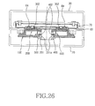
- a rotary washer 400 so that the second hinge frame 200 is rotated while being opposite to the first hinge frame 100, as shown in Fig. 25.
- a pair of fixing protrusions 402 which are securely fitted in fixing grooves 201a formed at the cylindrical hinge housing 201, respectively. Consequently, the fixing protrusions 402 are securely fitted in the corresponding fixing holes 201a (Fig. 26).
- the rotary washer 400 is provided with one or more washer protrusions 401, which are spaced uniformly apart from each other in the circumferential direction of the washer 400, so that the washer protrusions 401 are engaged in washer grooves 103 formed at the first hinge frame 100.
- a compression spring 600 Between the second hinge frame 200 and the rotary washer 400 is disposed a compression spring 600, as shown in Fig. 26.
- the washer protrusions 401 are securely located in the corresponding washer grooves 103 of the first hinge frame 100.
- the compression spring 600 generates an elastic force by which the washer protrusions 401 are engaged in or disengaged from the washer grooves 103, respectively.
- a pair of rotary stoppers 105 which contact the second hinge frame 200 for stopping the rotation of the slide housing 30.
- the washer protrusions 401 of the rotary washer 400 are separated from an initial set of corresponding washer grooves 103, and are then inserted into a different set of corresponding washer grooves 103, respectively.
- An elastic force is applied to the rotary washer 400 by means of the compression spring 600 in such a manner that the washer protrusions 401 are engaged into and disengaged from the corresponding washer grooves 103, while the slide housing 30 is being rotated.
- the sliding type mobile terminal includes a body housing 20, having a keypad 21 comprising a plurality of keys disposed thereon, and a slide housing 30, having a liquid crystal display unit 31 disposed thereon.
- a first hinge frame 40 of the sliding/hinge apparatus 10 of the sliding/rotating type mobile terminal is fixed to the body housing 20 by means of screws 93.
- a second hinge frame 50 At the upper part of the first hinge frame 40 is disposed a second hinge frame 50 while the second hinge frame 50 is opposite to the first hinge frame 40 in such a manner that the slide housing 30 can be slid and rotated about a hinge axis A1.
- a bush 91 Through the center parts of the first and second hinge frames 40 and 50 is inserted a bush 91 so that the first and second hinge frames 40 and 50 are coupled with each other while they are opposite to each other, as shown in Fig. 28.
- a snap ring 92 In a fitting groove at the lower end of the bush 91 is fitted a snap ring 92.
- To the upper part of the second hinge frame 50 To the upper part of the second hinge frame 50 is attached a first plate 60 in such a manner that the slide housing 30 is slid.
- the first plate 60 is fixed to the slide housing 30 by means of screws 93.
- a pair of first slide bars 81 are slid along a pair of guide grooves 55 formed at the upper part of the second hinge frame 50, respectively, since the first slide bars 301 are engaged in the pair of guide grooves 55 while being disposed between the second hinge frame 50 and the first plate 60.
- a pair of ring springs 94 for providing an elastic force, by which the slide housing 30 is semi-automatically slid.
- one end 94a of each of the ring springs 94 is inserted through the corresponding one of the guide holes 65 of the first plate 60 such that the end 94a is engaged in a supporting groove 58 formed at the upper end of the second hinge frame 50, and the other end 94b of each of the ring springs 94 is connected to the corresponding one of pins 73 formed at the second plate 60.
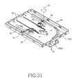
- a guide pin 2000 which is slidably moved.
- a pin guide hole 1000 in which the guide pin 2000 is disposed in such a manner that the guide pin 2000 is slid and rotated.
- the slide housing 30 is placed on the body housing 20 in the shape of a "T".
- the guide pin 2000 is slid along the pin guide hole 1000, as shown in Fig. 30.
- the upper part of the pin guide hole 1000 is formed with a prescribed length in the longitudinal direction of the first plate 60. Consequently, the guide pin 2000 can be slid along the pin guide hole 1000.
- the lower part of the pin guide hole 1000 is curved such that the slide housing is rotated. Consequently, the guide pin 2000 is guided along the curved lower part of the pin guide hole 1000 so that the slide housing is rotated, when the slide housing 30 is rotated as shown in Fig. 31.
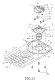
- a first hinge frame 3000 of the sliding/hinge apparatus 10 for sliding/rotating type mobile terminals is fixed to a body housing 20 by fitting screws 930 in screw fitting parts 4005.
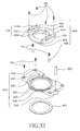
- a second hinge frame 4000 At the upper part of the first hinge frame 3000 is disposed a second hinge frame 4000, while the second hinge frame 4000 is opposite to the first hinge frame 3000 in such a manner that a slide housing is rotated about a hinge axis A1, as shown in Figs. 32 to 34.
- a cylinder 4002 As shown in Fig. 33, which extends downward in the direction of the hinge axis A1, so that the first and second hinge frames 3000 and 4000 are rotatably connected to each other while being opposite to each other.
- a first hinge frame side through-hole 3001 Through the center part of the first hinge frame 3000 is formed a first hinge frame side through-hole 3001, through which the cylinder 4002 is inserted.
- a snap ring 4007 is fitted in a fitting groove formed at the lower end of the cylinder 4002.
- a second hinge frame side through-hole 4001 Through the center part of the second hinge frame 4000 is formed a second hinge frame side through-hole 4001, through which a flexible circuit (not shown) can be inserted, as shown in Figs. 32 and 33.
- a second plate side through-hole 6004 At a prescribed position of the second plate 6000 is formed a second plate side through-hole 6004, through which the flexible circuit is inserted.
- second plate side screw holes 6005 are formed at prescribed positions of both sides of the second plate 6000, which are arranged in the longitudinal direction of the plate 6000 so that the second plate 6000 is fixed to the slide housing by fitting screws 930 in the second plate side screw holes 6005.
- the first plate 5000 is fixed to the second hinge frame 4000 by means of screws, and a first slide bar 7000 and a second slide bar 8000 are fixed to both sides of the first plate 5000 by means of screws 930.
- bar fixing parts 5001 which are disposed in the longitudinal direction of the slide housing 30.
- the slide bars 7000 and 8000 are fixed to the bar fixing parts 5001 by means of screws 930.
- the first slide bar 7000 is provided at one side thereof with a guide protrusion 7001, which is formed in the longitudinal direction of the plate 5000.
- the second slide bar 8000 is provided at one side thereof with a guide protrusion 8001, which is formed in the longitudinal direction of the plate 5000.
- the guide protrusions 7001 and 8001 are disposed in the guide grooves 6001 in such a manner that the guide protrusions 7001 and 8001 are slid.
- the first hinge frame 3000 is provided at a prescribed position thereof with a pin hole 3005, in which a guide pin 9000 can move slidably along a guide 6002 formed at the second plate 6000 is fitted.
- the guide pin 9000 fitted in the pin hole 3005 is linearly slid along the guide 6002.
- the upper part 6002a of the guide 6002 is formed with a prescribed length in the longitudinal direction of the second plate 6000 so that the guide pine 9000 is linearly slid along thereof.
- a pair of ring springs 940 are disposed, as shown in Fig. 42, between the first and second plates 5000 and 6000 for providing an elastic force, by which the slide housing 30 is semi-automatically slid. Through one end of each of the ring springs 940 is inserted a rivet pin 950 (Fig. 34), which is fitted in a rivet pin hole 5004 formed at the first plate 5000. The other end of each of the ring springs 940 is inserted through a spring insertion hole 603 formed at the second plate 6000.
- one or more ball grooves 3002 are formed around the first hinge frame side through-hole 3001 , which are arranged while being spaced uniformly apart from each other in a circumferential manner, so that balls 4004 are securely located in the ball grooves 3002, respectively.
- a ball guide groove 3003 is formed such that the ball grooves 43 are connected to each other by means of the ball guide groove 3003. The balls 4004 are guided along the ball guide groove 3003.
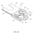
- compression springs 570 Inside the lower ends of the cylinder 4002 of the second hinge frame 4000 are provided compression springs 570, as shown in Figs. 45 and 47.
- a pair of spring holes 4003 Around the cylinder 4002 are formed a pair of spring holes 4003, which are opposite to each other.
- a pair of balls 4004 In the pair of spring holes 4003 are disposed a pair of balls 4004, respectively, such that the balls 4006 emerge from the lower ends of the spring holes 4003, respectively, by means of an elastic force from the compression springs 570.
- the balls 4004 are mounted in the corresponding spring holes 4003 in such a manner that the balls 4004 are selectively engaged in the ball grooves 3002 (Fig. 37) of the first hinge frame 3000, respectively.
- the balls 4004 are separated from an initial set of corresponding ball grooves 3002, and are then inserted into a different set of corresponding ball grooves 3002, respectively.
- the balls 4004 are guided along the ball guide groove 3003 connected to the ball grooves 3002.
- a pair of fixing parts 4005 is formed around the second hinge frame 4000 , which are fixed to the first plate 5000, so that the first plate 5000 is securely fixed to the fixing parts 4005.
- Each of the fixing parts 4005 is provided with a fixing protrusion 4005a.
- the first plate 5000 is provided with fixing holes 5002, in which the fixing protrusions 4005a are fitted, respectively.
- each of the fixing protrusion 4005a At both sides of each of the fixing protrusion 4005a are formed one or more fitting grooves 4005b, in which one or more screw fitting parts 5003 are formed at the first plate 5000.
- a screw hole 4005c In each of the fitting grooves 4005b is formed a screw hole 4005c.
- the screw fitting parts 5003 extend downwards from the first plate 5000 so that the screw fitting parts 5003 are fitted in the fitting grooves 4005b of the second hinge frame 4000, respectively.
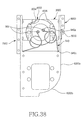
- a stopper 4006 At one side of each of the fixing parts 4005 is formed a stopper 4006, which contacts the stopper protrusion 3004 of the first hinge frame 3000 for stopping the rotation of the slide housing 30.
- the stopper 4006 contacts the stopper protrusion 3004, whereby rotation of the slide housing 30 is stopped.
- the guide pin 9000 is rotated along the curved lower part 6002b of the guide 6002.
- the sliding/rotating type mobile terminal comprises a body housing 20 and a slide housing 30.
- the sliding/hinge apparatus of the sliding/rotating type mobile terminal comprises first and second hinge frames 1 and 2, first and second plates 3 and 4, a guide unit 5, and a guide pin 6.
- the first hinge frame 1 is inserted into a housing side insertion groove 24 formed at a prescribed position of the upper surface of the body housing 20.
- the second hinge frame 2 Along the outer edges of the second hinge frame 2 are formed one or more screw coupling holes 2f, through which screws 930 are inserted so that the second hinge frame 2 is attached to the first plate 3 by means of the screws 930.
- the screws 930 protrude from the corresponding screw coupling holes 2f, and are securely inserted into one or more screw holes 3c formed at the first plate 3.
- one or more screw grooves 25 are formed along the outer edge of the housing side insertion groove 24 while being uniformly spaced apart from each other. Screw coupling parts 1e formed at the first hinge frame 1 are inserted into the screw grooves 25, respectively, and the screws 930 are inserted into the screw coupling parts 1e of the first hinge frame 1.
- first plate 3 At the lower surface of the first plate 3 are formed one or more screw supporting protrusions 3h for supporting the screw holes, respectively, as shown in Fig. 59.
- One or more coupling protrusions 2g formed at the second hinge frame 2 are inserted into one or more plate side fixing holes 3d formed at prescribed positions of the first plate 3, respectively.
- each ring spring 940 is arranged such that the end of each ring spring 940 is exactly located in the corresponding rivet pin groove 3e, and then the rivet pins 950 are securely inserted into the rivet pin grooves 3e, respectively.
- the guide unit 5 comprises guide protrusions 5a formed at first and second slide bars 3a and 3b of the first plate 3 and guide rails 5b formed at the second plate 4.
- the first and second slide bars 3a and 3b are formed at both sides of the first plate 3 in the longitudinal direction of the slide housing 30.
- the guide protrusions 5a are protruded toward the inside part of the first plate 3.
- the second plate 4 is inserted between the first and second slide bars 3a and 3b.
- the guide rails 5b formed at both sides of the second plate 4 are engaged with the guide protrusions 5a, respectively, such that the guide rails 5b can be slid.
- spring fixing holes 4d At prescribed positions of the second plate 4 are formed spring fixing holes 4d, which are connected to the other end of each ring spring 940.
- shock-absorbing members 7 Attached to both ends of the first and second slide bars 3a and 3b are shock-absorbing members 7, which absorb shock caused due to contact of the plates 3 and 4 and the slide housing 30 when the plates 3 and 4 are slid.
- the shock-absorbing members 7 are attached to the first and second slide bars 3a and 3b in the longitudinal directions of the first and second slide bars 3a and 3b, respectively.
- the second hinge frame 2 is mounted on the upper surface of the first hinge frame 1 in such a manner that the second hinge frame 2 can be rotated about a hinge axis A1 while the second hinge frame 2 is opposite to the first hinge frame 1.
- Formed at the lower surface of the first hinge frame 1 are one or more fixing protrusions 1f, which are securely inserted into one or more fixing holes 26 formed in the housing side insertion groove 24, respectively.
- a cylinder 2b is formed at the center part of the second hinge frame 2.
- the cylinder 2b extends downward in the direction of the hinge axis A1 so that the first and second hinge frames 1 and 2 can be rotatably coupled with each other while the first and second hinge frames 1 and 2 are opposite to each other.
- the cylinder 2b is inserted through a first hinge frame side through-hole 1a formed at the center part of the first hinge frame 1, and then a stopper ring 4007 is fitted in a fitting groove formed at one end of the cylinder 2b.
- a friction-preventing ring 8 At the upper surface of the stopper ring 4007 is disposed a friction-preventing ring 8, which prevents friction due to rotation of the slide housing 30.
- a second hinge frame side through-hole 2a is formed at the center part of the second hinge frame 2 .
- a flexible circuit (not shown) is inserted.
- a second plate side through-hole 4e is formed at the center part of the second hinge frame 2 at the center part of the second hinge frame 2 at the center part of the second hinge frame 2 at the center part of the second hinge frame 2 at the center part of the second hinge frame 2 at the center part of the second hinge frame 2 is formed at the center part of the second hinge frame 2a, through which a flexible circuit (not shown) is inserted.
- second plate side screw holes 4f are formed at prescribed positions of both sides of the second plate 4 in the longitudinal direction of the plate 4.
- the second plate 4 is attached to the slide housing 30 by inserting the screws 930 into the second plate side screw holes 4f.
- the slide housing 30 is slid as shown in Fig. 55, the guide rails 5b formed at the first plate 3 are guided along the guide protrusions 5a formed at the first and second slide bars 3a and 3b.
- a stopper pin 6 is formed at a prescribed position of the upper surface of the body housing, as shown in Figs. 56 and 57by which the second plate 4 can be slid and rotated, and the slid and rotated second plate 4 can be stopped.
- the stopper pin 6 contacts a straight guide part 4a, which is formed at the second plate 4 so that the second plate 4 can be guided by means of the stopper pin 6 when the second plate 4 is slid.
- a pair of ring springs 940 is disposed between the first and second plates 3 and 4 for providing an elastic force by which the sliding housing 30 can be semi-automatically slid.
- One end of each ring spring 940, through which the corresponding rivet pin 950 is inserted, is securely fitted in the corresponding rivet pin groove 3e formed at the first plate 3 (Fig. 48).
- the other end of each ring spring 940 is fixedly inserted into a corresponding spring side fixing hole 4d formed at the second plate 4.
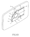
- a stopper part 3g which stops the sliding movement of the slide housing 30 when the stopper part 3g contacts the inside of the slide housing 30, as shown in Figs. 59 and 60.
- the second plate 4 is moved as the slide housing 30 is slid, the inside of the slide housing 30 contacts the stopper part 3g, and at the same time the sliding movement of the slide housing 30 is stopped.
- Latching protrusions 4c are formed at the lower ends of the guide parts 4a and 4b, as shown in Fig. 60, which are engaged with a latching member 3f of the first plate 3.
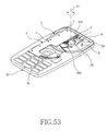
- the slide housing 30 is slid and then rotated as shown in Fig. 61, the sliding housing 30 and the body housing 20 are arranged in the shape of a "T".
- a ball guide groove 1b is formed around the first hinge frame side through-hole 1a, in the circumferential direction thereof, as shown in Figs. 62 to 64, along which a ball 2d is guided so that the slide housing 30 can be rotated.
- the ball 2d which is provided in the second hinge frame 2 is guided along the ball guide grooves 1b, whereby the second hinge frame 2 is rotated.
- At both ends of the ball guide groove 1b are formed ball grooves 1c, respectively, in which the ball 2d is securely located, as shown in Figs. 63 and 64.
- the ball 2d is disengaged from one of the ball grooves 1c, moved along the ball guided groove 1b, and engaged into the other ball groove 1c, so that the rotatability of the second hinge frame 2 is improved.
- a spring hole 2c is formed at the position next to the cylinder 2b of the second hinge frame 2 having a compression spring 570 disposed therein, as shown in Fig. 64.
- the ball 2d is disposed in the spring hole 2c such that the ball 2d emerges from the lower end of the spring hole 2c by means of the elastic force of the compression spring 570.
- the ball 2d is securely located in the ball guide groove 1b or the ball grooves 1c so that the slide housing 30 can be rotated or the rotation of the slide housing 30 can be stopped, respectively.
- a stopper hole 2e is formed between the second hinge frame side through-hole 2a and the spring hole 2c, along the circumference of the through-hole 2a, in which a stopper protrusion 1d is engaged so that the slide housing 30 is guided and simultaneously the rotation of the slide housing 30 is stopped.
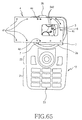
- the slide housing 30 is rotated as shown in Fig. 65, the slide housing 30 is rotated along a curved guide part 4b formed at the second plate 4.
- the plates 3 and 4 can be slid and rotated by means of the stopper pin 6 formed at the body housing 20. Also, the slid and rotated plates 3 and 4 are stopped by means of the stopper pin 6.
- An engaging surface 4c is formed at one end of the second plate 4, in which the stopper pin 6 is securely located. When the stopper pin 6 is securely located in the engaging surface 4c, the sliding movement and rotation of the plates 3 and 4 are stopped.
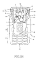
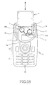
- the body housing 20 is provided with a microphone unit 23 and a plurality of keypads 21.
- the body housing 20 is also provided with a plurality of auxiliary keypads 22, which are arranged adjacent to the keypads 21.
- the sliding housing 30 is provided with a plurality of auxiliary keypads 33 and a speaker unit 32.
Applications Claiming Priority (4)
| Application Number | Priority Date | Filing Date | Title |
|---|---|---|---|
| KR20030080342 | 2003-11-13 | ||
| KR2003080342 | 2003-11-13 | ||
| KR1020040028590A KR100681068B1 (ko) | 2003-11-13 | 2004-04-26 | 슬라이딩/회전 타입 휴대 단말기의 슬라이딩/힌지 장치 |
| KR2004028590 | 2004-04-26 |
Publications (3)
| Publication Number | Publication Date |
|---|---|
| EP1531604A2 true EP1531604A2 (de) | 2005-05-18 |
| EP1531604A3 EP1531604A3 (de) | 2010-12-22 |
| EP1531604B1 EP1531604B1 (de) | 2012-12-19 |
Family
ID=34437031
Family Applications (1)
| Application Number | Title | Priority Date | Filing Date |
|---|---|---|---|
| EP04026954A Expired - Fee Related EP1531604B1 (de) | 2003-11-13 | 2004-11-12 | Verschiebbare Gelenkvorrichtung für drehbare und verschiebbare Mobilgeräte |
Country Status (5)
| Country | Link |
|---|---|
| US (1) | US7529571B2 (de) |
| EP (1) | EP1531604B1 (de) |
| JP (1) | JP4343817B2 (de) |
| CN (1) | CN100405801C (de) |
| AU (1) | AU2004229031B2 (de) |
Cited By (13)
| Publication number | Priority date | Publication date | Assignee | Title |
|---|---|---|---|---|
| WO2006127325A1 (en) * | 2005-05-25 | 2006-11-30 | Motorola Inc. | Wireless communication device and method of operation thereof |
| EP1703704A3 (de) * | 2005-03-17 | 2007-04-11 | Samsung Electronics Co., Ltd. | Verschiebbare und drehbare Vorrichtung für ein Mobilgerät |
| EP1773029A1 (de) * | 2005-10-07 | 2007-04-11 | Samsung Electronics Co., Ltd. | Schiebe-Typ, tragbares Kommunikationsgerät und Schiebegerät davon, oberer Teil des Geräts sich bewegend entlang einer Kurve |
| EP1798941A1 (de) * | 2005-12-19 | 2007-06-20 | Samsung Electronics Co., Ltd. | Gelenkvorrichtung und mobile Vorrichtung, die dieselbe hat |
| WO2007069834A1 (en) * | 2005-12-13 | 2007-06-21 | Laird Technologies Map Co., Ltd | A swing mechanism for display part of cellular phone |
| EP1814285A1 (de) * | 2006-01-26 | 2007-08-01 | Samsung Electronics Co.,Ltd. | Tragbares Endgerät mit Gleit-/Schwenk-Mechanismus und Funktion zur zentralen Positionierung der Flüssigkristallanzeige sowie Verwendungsverfahren dafür |
| EP1883206A1 (de) * | 2006-07-27 | 2008-01-30 | Sharp Kabushiki Kaisha | Zusammenklappbare und tragbare Kommunikationsvorrichtung |
| WO2009017313A2 (en) * | 2007-07-30 | 2009-02-05 | P & Tel Inc. | Combined mechanism for sliding movement and rotating movement and a portable electronic appliance employing the same |
| US7703177B2 (en) | 2005-12-19 | 2010-04-27 | Samsung Electronics Co., Ltd. | Hinge device and mobile apparatus having the same |
| CN101725620B (zh) * | 2008-10-29 | 2012-03-28 | 鸿富锦精密工业(深圳)有限公司 | 铰链结构及采用该铰链结构的电脑机箱 |
| EP1777920A3 (de) * | 2005-10-20 | 2012-08-08 | LG Electronics Inc. | Ein Mobilendgerät |
| DE102007046477B4 (de) * | 2006-09-29 | 2014-10-09 | Lg Electronics Inc. | Mobiles Endgerät sowie mit diesem gekoppelte Dreheinrichtung |
| EP2296354B1 (de) * | 2009-09-11 | 2015-10-14 | HTC Corporation | Tragbare elektronische Vorrichtung |
Families Citing this family (95)
| Publication number | Priority date | Publication date | Assignee | Title |
|---|---|---|---|---|
| USD652403S1 (en) | 2011-03-03 | 2012-01-17 | Nokia Corporation | Handset |
| US7079874B2 (en) * | 2002-12-20 | 2006-07-18 | Nokia Corporation | Transformer hinge design |
| US8155718B2 (en) * | 2003-09-03 | 2012-04-10 | Samsung Electronics Co., Ltd. | Sliding/hinge apparatus for sliding/rotating type mobile terminals |
| KR100566276B1 (ko) * | 2003-10-17 | 2006-03-30 | 삼성전자주식회사 | 휴대용 단말기 및 그의 스윙 힌지 모듈 |
| JP2005207562A (ja) * | 2004-01-26 | 2005-08-04 | Kato Electrical Mach Co Ltd | スライド機構 |
| WO2005091515A1 (en) * | 2004-02-10 | 2005-09-29 | Hansang Lee | Sliding mechanism apparatus and appliance integrated with the same |
| KR100704031B1 (ko) * | 2004-04-29 | 2007-04-04 | 삼성전자주식회사 | 이중 슬라이딩 타입 휴대용 통신 장치 |
| KR100616197B1 (ko) | 2004-08-24 | 2006-08-25 | 삼성전자주식회사 | 이중 슬라이딩 타입 휴대용 통신 장치의 슬라이딩 장치 |
| TWI254199B (en) * | 2004-08-31 | 2006-05-01 | Benq Corp | Slidable and automatic rotatable apparatus |
| KR100575947B1 (ko) * | 2004-09-17 | 2006-05-02 | 삼성전자주식회사 | 휴대 장치용 슬라이딩 스윙 장치 |
| EP1798940A4 (de) * | 2004-10-01 | 2010-03-17 | Sharp Kk | Mobil-informationsendgerät |
| KR100617673B1 (ko) * | 2004-12-06 | 2006-08-28 | 삼성전자주식회사 | 슬라이딩 타입 휴대 단말기의 슬라이딩 모듈 및 이를채용하는 슬라이딩 타입 휴대 단말기 |
| KR100721337B1 (ko) * | 2004-12-22 | 2007-05-28 | 엘지전자 주식회사 | 사이드 슬라이딩형 전자장치 |
| KR100675360B1 (ko) * | 2005-01-07 | 2007-01-29 | 삼성전자주식회사 | 슬라이드형 이동통신 단말기 |
| KR100678265B1 (ko) * | 2005-01-11 | 2007-02-02 | 삼성전자주식회사 | 휴대 단말기의 반 자동 스윙 장치 |
| KR100651471B1 (ko) * | 2005-01-12 | 2006-11-29 | 삼성전자주식회사 | 슬라이딩-폴딩 타입 휴대용 단말기 |
| KR100631897B1 (ko) * | 2005-01-19 | 2006-10-11 | 삼성전기주식회사 | 경사 개폐 방식 이동통신단말기 |
| KR100662869B1 (ko) * | 2005-02-04 | 2007-01-02 | 삼성전자주식회사 | 단말기 |
| WO2006092979A1 (ja) * | 2005-03-04 | 2006-09-08 | Matsushita Electric Industrial Co., Ltd. | 携帯無線装置 |
| KR20060098028A (ko) * | 2005-03-08 | 2006-09-18 | 피닉스코리아 주식회사 | 휴대전화기용 스윙힌지 |
| KR101106333B1 (ko) * | 2005-03-10 | 2012-01-19 | 엘지전자 주식회사 | 데이터 입력부 및 숫자 입력부를 갖는 복합 개폐형 이동통신 단말기 |
| KR100709808B1 (ko) * | 2005-03-31 | 2007-04-23 | 주식회사 팬택 | 회전 슬라이드형 이동통신 단말기 |
| US9203938B2 (en) * | 2005-04-06 | 2015-12-01 | Nokia Technologies Oy | Extensible mobile electronic device |
| US7447528B2 (en) * | 2005-04-12 | 2008-11-04 | Nokia Corporation | Multifunction electronic device |
| TWI333367B (en) * | 2005-04-14 | 2010-11-11 | High Tech Comp Corp | Hand-held wireless communication apparatus with ceramic screws |
| JP3936956B2 (ja) * | 2005-05-23 | 2007-06-27 | シャープ株式会社 | 携帯通信端末 |
| US8041405B2 (en) * | 2005-06-01 | 2011-10-18 | Panasonic Corporation | Stack type mobile terminal |
| JP4548238B2 (ja) * | 2005-06-20 | 2010-09-22 | パナソニック株式会社 | 開閉装置及びこれを用いた電子機器 |
| JP4537930B2 (ja) * | 2005-10-07 | 2010-09-08 | 加藤電機株式会社 | 携帯機器の水平回転機構 |
| KR100810263B1 (ko) * | 2005-10-11 | 2008-03-07 | 삼성전자주식회사 | 휴대용 단말기의 키패드, 슬라이딩 모듈 및 그의 연성 회로 |
| WO2007080639A1 (ja) * | 2006-01-12 | 2007-07-19 | Matsushita Electric Industrial Co., Ltd. | スライド装置、及びこれを備えた携帯端末 |
| KR100678215B1 (ko) * | 2006-04-07 | 2007-02-02 | 삼성전자주식회사 | 휴대 단말기 및 그의 슬라이딩 거치 장치 |
| KR100833241B1 (ko) * | 2006-04-28 | 2008-05-28 | 삼성전자주식회사 | 슬라이딩-틸트장치 및 이를 채용한 모바일 기기 |
| EP1887761A3 (de) * | 2006-08-08 | 2012-12-26 | Samsung Electronics Co., Ltd. | Mobile Kommunikationsvorrichtung mit einem eine Qwerty-Tastatur überdeckenden schieb- und drehbarem Gehäuse |
| TWI325712B (en) * | 2006-08-16 | 2010-06-01 | Htc Corp | Handheld electronic apparutus with mutiple opertaing configurations |
| KR100800677B1 (ko) * | 2006-09-07 | 2008-02-01 | 삼성전자주식회사 | 휴대 단말기의 다축 힌지 장치 및 이를 구비한 연결 부재 |
| JP2008076818A (ja) * | 2006-09-22 | 2008-04-03 | Fujitsu Ltd | 携帯端末装置 |
| JP4484859B2 (ja) | 2006-10-19 | 2010-06-16 | シャープ株式会社 | スライド式携帯機器 |
| KR101105770B1 (ko) * | 2006-10-20 | 2012-01-17 | 엘지전자 주식회사 | 색상 변화기능을 구비한 단말기 및 그 색상 변화방법 |
| TW200826606A (en) * | 2006-12-06 | 2008-06-16 | Benq Corp | Sliding hinge and electronic device using the same |
| KR100842626B1 (ko) * | 2007-04-10 | 2008-06-30 | 삼성전자주식회사 | 슬라이딩 스윙 타입 휴대 단말기의 락킹 장치 |
| US7646866B2 (en) * | 2007-04-16 | 2010-01-12 | Cheng Uei Precision Industry Co., Ltd. | Slide module for a slide type electronic device |
| JP4580958B2 (ja) * | 2007-04-27 | 2010-11-17 | 株式会社ストロベリーコーポレーション | スライド装置並びにスライド装置を用いた電子機器 |
| KR100842562B1 (ko) * | 2007-05-08 | 2008-07-01 | 삼성전자주식회사 | 슬라이딩 형 휴대 단말기의 슬라이딩 장치 |
| US8478368B2 (en) * | 2007-07-30 | 2013-07-02 | Htc Corporation | Portable electronic device |
| JP5439816B2 (ja) | 2007-10-11 | 2014-03-12 | 日本電気株式会社 | 携帯型情報処理端末 |
| CN101460033A (zh) * | 2007-12-11 | 2009-06-17 | 鸿富锦精密工业(深圳)有限公司 | 滑动机构 |
| US7752712B2 (en) * | 2008-01-21 | 2010-07-13 | Shin Zu Shing Co., Ltd. | Hinge |
| JP4899191B2 (ja) * | 2008-01-21 | 2012-03-21 | Necカシオモバイルコミュニケーションズ株式会社 | 携帯電子機器 |
| USD635142S1 (en) | 2008-01-22 | 2011-03-29 | Ymax Communications Corp. | USB device for facilitating VoIP calls |
| JP2009187059A (ja) * | 2008-02-01 | 2009-08-20 | Kato Electrical Mach Co Ltd | 電子機器 |
| US7991443B2 (en) * | 2008-02-04 | 2011-08-02 | Shin Zu Shing Co., Ltd. | Sliding hinge |
| JP4968157B2 (ja) * | 2008-04-15 | 2012-07-04 | 富士通株式会社 | 情報端末 |
| JP5112214B2 (ja) * | 2008-08-04 | 2013-01-09 | スタッフ株式会社 | スライド回転ヒンジ |
| JPWO2010023961A1 (ja) * | 2008-08-29 | 2012-01-26 | 日本電気株式会社 | スライド機構及びこれを備えた携帯型通信端末、並びにスライド移動方法 |
| US8504115B2 (en) * | 2008-11-21 | 2013-08-06 | Plantronics, Inc. | Automatic sidetone control |
| JP5135241B2 (ja) * | 2009-01-22 | 2013-02-06 | スタッフ株式会社 | スライド回転ヒンジ |
| JP5448143B2 (ja) * | 2009-01-23 | 2014-03-19 | Necカシオモバイルコミュニケーションズ株式会社 | 回転ヒンジ、及び携帯機器 |
| US8463326B2 (en) * | 2009-02-23 | 2013-06-11 | Research In Motion Limited | Handheld electronic device transitionable between different configurations |
| JP5124060B2 (ja) * | 2009-03-23 | 2013-01-23 | スタッフ株式会社 | スライド回転ヒンジ |
| US8023975B2 (en) * | 2009-03-23 | 2011-09-20 | T-Mobile Usa, Inc. | Secondary status display for mobile device |
| US8224407B2 (en) * | 2009-03-23 | 2012-07-17 | T-Mobile Usa, Inc. | Mobile device having a movable display and associated systems and methods |
| JP5110024B2 (ja) * | 2009-03-31 | 2012-12-26 | 富士通株式会社 | 情報処理端末 |
| KR101594179B1 (ko) * | 2009-07-30 | 2016-02-16 | 삼성전자주식회사 | 힌지 장치를 구비하는 휴대용 단말기 |
| KR101587138B1 (ko) * | 2009-08-27 | 2016-02-02 | 엘지전자 주식회사 | 이동 단말기 |
| US8305747B2 (en) * | 2010-01-08 | 2012-11-06 | Shin Zu Shing Co., Ltd. | Rotary hinge and a portable electronic device with the same |
| KR101621563B1 (ko) | 2010-02-08 | 2016-05-17 | 삼성전자주식회사 | 스윙 타입 휴대용 통신 장치 및 그의 힌지 장치 |
| US8437814B2 (en) * | 2010-02-10 | 2013-05-07 | Sony Corporation | Slide opening/closing device, method of restricting sliding movement of slide member, electronic apparatus, and mobile terminal device |
| JP5546975B2 (ja) * | 2010-07-05 | 2014-07-09 | 三菱製鋼株式会社 | 開閉機構 |
| WO2012011916A1 (en) * | 2010-07-23 | 2012-01-26 | Sony Ericsson Mobile Communications Ab | Double-folded flexible printed circuit board for slider devices |
| KR101750117B1 (ko) * | 2011-01-10 | 2017-06-22 | 삼성전자주식회사 | 휴대용 통신 장치의 거치 장치 |
| US8630089B2 (en) | 2011-01-21 | 2014-01-14 | Blackberry Limited | Resilient swivel coupling mechanism |
| CA141527S (en) * | 2011-02-15 | 2012-03-09 | Lg Electronics Inc | Mobile phone |
| US8498102B2 (en) | 2011-03-04 | 2013-07-30 | Research In Motion Limited | Rotatable coupling mechanism |
| JP5849414B2 (ja) * | 2011-03-18 | 2016-01-27 | 富士通株式会社 | 電子機器 |
| US8471820B2 (en) | 2011-03-28 | 2013-06-25 | Research In Motion Limited | Pivotable display guide mechanism for an electronic mobile device |
| US8693188B2 (en) | 2011-05-24 | 2014-04-08 | Blackberry Limited | Pivotable display guide mechanism for an electronic mobile device |
| USD665763S1 (en) * | 2011-07-15 | 2012-08-21 | Chi Mei Communication Systems, Inc. | Mobile phone |
| CN103153011B (zh) * | 2011-12-07 | 2017-02-15 | 富泰华工业(深圳)有限公司 | 滑动机构及带有该滑动机构的装置 |
| US9210242B2 (en) * | 2012-08-31 | 2015-12-08 | Apple Inc. | Device housings with hidden fasteners |
| TWI476569B (zh) * | 2012-09-24 | 2015-03-11 | Quanta Comp Inc | 攜帶式電子裝置 |
| USD735175S1 (en) * | 2013-01-30 | 2015-07-28 | Htc Corporation | Display module for an electronic device |
| USD735176S1 (en) * | 2013-01-30 | 2015-07-28 | Htc Corporation | Display module for an electronic device |
| USD746281S1 (en) * | 2014-02-03 | 2015-12-29 | Lg Electronics Inc. | Tablet computer |
| USD762628S1 (en) * | 2014-03-06 | 2016-08-02 | Lg Electronics Inc. | Cellular phone |
| USD770409S1 (en) * | 2014-04-09 | 2016-11-01 | Hisense Mobile Communications Technology Co., Ltd. | Handset |
| USD778252S1 (en) * | 2014-05-13 | 2017-02-07 | Isaac S. Daniel | Communication device with biometric verification means |
| USD779448S1 (en) * | 2014-05-13 | 2017-02-21 | Isaac S. Daniel | Communication device with biometric verification means |
| KR20170028719A (ko) * | 2015-09-04 | 2017-03-14 | 엘지전자 주식회사 | 이동 단말기 |
| USD786223S1 (en) * | 2016-03-04 | 2017-05-09 | Assa Abloy Ab | Reader module bracket |
| US10311265B2 (en) * | 2016-03-04 | 2019-06-04 | Assa Abloy Ab | Universal mounting ring |
| US10051749B2 (en) * | 2016-07-24 | 2018-08-14 | Lg Electronics Inc. | Display device |
| US10890288B2 (en) | 2018-04-13 | 2021-01-12 | Microsoft Technology Licensing, Llc | Systems and methods of providing a multipositional display |
| KR20200124989A (ko) * | 2019-04-25 | 2020-11-04 | 엘지전자 주식회사 | 롤-슬라이드 이동 단말기 |
| US11493953B2 (en) * | 2019-07-01 | 2022-11-08 | Microsoft Technology Licensing, Llc | Multi-position display with an unfixed center of rotation |
Citations (7)
| Publication number | Priority date | Publication date | Assignee | Title |
|---|---|---|---|---|
| WO2003050665A1 (en) * | 2001-12-06 | 2003-06-19 | Rast Associates, Llc | Articulated, rotatable expandable and contractive keyboard device |
| SE520967C2 (sv) * | 1999-03-17 | 2003-09-16 | Ericsson Telefon Ab L M | En handhållen apparat |
| EP1357726A1 (de) * | 2002-04-26 | 2003-10-29 | Nec Corporation | Tragbares Telefon mit einer drehbaren Anzeigevorrichtung und zwei Kameras |
| JP2003338866A (ja) * | 2002-05-22 | 2003-11-28 | Fujitsu Ltd | 携帯電話機 |
| US20040085739A1 (en) * | 2002-11-19 | 2004-05-06 | Jae-Gab Lee | Sliding-type portable wireless terminal |
| EP1577975A1 (de) * | 2004-03-18 | 2005-09-21 | Sagem SA | Zweiteiliges Telefon mit Planar-Antenne |
| EP1638295A1 (de) * | 2004-09-17 | 2006-03-22 | Samsung Electronics Co., Ltd. | Tragbares Gerät mit verschiebbaren Gehäuseteilen und einem drehbaren Gehäuseteil |
Family Cites Families (13)
| Publication number | Priority date | Publication date | Assignee | Title |
|---|---|---|---|---|
| JPS57127237A (en) | 1981-01-31 | 1982-08-07 | Pentel Kk | Character information input device |
| JP3751197B2 (ja) * | 2000-10-02 | 2006-03-01 | 株式会社ケンウッド | 移動体電話機 |
| JP2003174495A (ja) * | 2001-09-28 | 2003-06-20 | Nec Corp | 折り畳み式携帯情報端末 |
| JP2003179678A (ja) * | 2001-10-03 | 2003-06-27 | Nec Corp | 携帯電話機 |
| JP3856682B2 (ja) | 2001-10-15 | 2006-12-13 | 加藤電機株式会社 | スライド機構 |
| JP2003129942A (ja) | 2001-10-23 | 2003-05-08 | Toshiaki Hirai | ウォータージェット発電装置 |
| AU2002348838A1 (en) | 2001-11-27 | 2003-06-10 | Koninklijke Philips Electronics N.V. | Electronic portable device |
| JP4360593B2 (ja) | 2002-02-15 | 2009-11-11 | ソニー・エリクソン・モバイルコミュニケーションズ株式会社 | ヒンジ構造及びモバイル情報端末機器 |
| US6941618B2 (en) * | 2002-09-13 | 2005-09-13 | Samsung Electronics Co., Ltd. | Hinge device for portable wireless terminal |
| JP4125653B2 (ja) * | 2002-10-30 | 2008-07-30 | 日本電気株式会社 | 携帯型情報端末装置 |
| JP3796222B2 (ja) | 2003-01-08 | 2006-07-12 | 三洋電機株式会社 | 携帯型無線端末機 |
| JP4192024B2 (ja) | 2003-04-17 | 2008-12-03 | 加藤電機株式会社 | 携帯端末用取付装置 |
| US6845546B1 (en) * | 2003-06-20 | 2005-01-25 | Shin Zu Shing Co., Ltd. | Hinge assembly with a rotation seat available to rotate in both latitudinal and longitudinal directions with respect to a fixing seat |
-
2004
- 2004-08-13 US US10/917,353 patent/US7529571B2/en not_active Expired - Fee Related
- 2004-11-10 AU AU2004229031A patent/AU2004229031B2/en not_active Ceased
- 2004-11-12 EP EP04026954A patent/EP1531604B1/de not_active Expired - Fee Related
- 2004-11-12 CN CNB2004100926938A patent/CN100405801C/zh not_active Expired - Fee Related
- 2004-11-15 JP JP2004331154A patent/JP4343817B2/ja not_active Expired - Fee Related
Patent Citations (7)
| Publication number | Priority date | Publication date | Assignee | Title |
|---|---|---|---|---|
| SE520967C2 (sv) * | 1999-03-17 | 2003-09-16 | Ericsson Telefon Ab L M | En handhållen apparat |
| WO2003050665A1 (en) * | 2001-12-06 | 2003-06-19 | Rast Associates, Llc | Articulated, rotatable expandable and contractive keyboard device |
| EP1357726A1 (de) * | 2002-04-26 | 2003-10-29 | Nec Corporation | Tragbares Telefon mit einer drehbaren Anzeigevorrichtung und zwei Kameras |
| JP2003338866A (ja) * | 2002-05-22 | 2003-11-28 | Fujitsu Ltd | 携帯電話機 |
| US20040085739A1 (en) * | 2002-11-19 | 2004-05-06 | Jae-Gab Lee | Sliding-type portable wireless terminal |
| EP1577975A1 (de) * | 2004-03-18 | 2005-09-21 | Sagem SA | Zweiteiliges Telefon mit Planar-Antenne |
| EP1638295A1 (de) * | 2004-09-17 | 2006-03-22 | Samsung Electronics Co., Ltd. | Tragbares Gerät mit verschiebbaren Gehäuseteilen und einem drehbaren Gehäuseteil |
Cited By (16)
| Publication number | Priority date | Publication date | Assignee | Title |
|---|---|---|---|---|
| EP1703704A3 (de) * | 2005-03-17 | 2007-04-11 | Samsung Electronics Co., Ltd. | Verschiebbare und drehbare Vorrichtung für ein Mobilgerät |
| WO2006127325A1 (en) * | 2005-05-25 | 2006-11-30 | Motorola Inc. | Wireless communication device and method of operation thereof |
| EP1773029A1 (de) * | 2005-10-07 | 2007-04-11 | Samsung Electronics Co., Ltd. | Schiebe-Typ, tragbares Kommunikationsgerät und Schiebegerät davon, oberer Teil des Geräts sich bewegend entlang einer Kurve |
| EP1777920A3 (de) * | 2005-10-20 | 2012-08-08 | LG Electronics Inc. | Ein Mobilendgerät |
| WO2007069834A1 (en) * | 2005-12-13 | 2007-06-21 | Laird Technologies Map Co., Ltd | A swing mechanism for display part of cellular phone |
| EP1798941A1 (de) * | 2005-12-19 | 2007-06-20 | Samsung Electronics Co., Ltd. | Gelenkvorrichtung und mobile Vorrichtung, die dieselbe hat |
| US7703177B2 (en) | 2005-12-19 | 2010-04-27 | Samsung Electronics Co., Ltd. | Hinge device and mobile apparatus having the same |
| US7870645B2 (en) | 2005-12-19 | 2011-01-18 | Samsung Electronics Co., Ltd. | Hinge device and mobile apparatus having the same |
| EP1814285A1 (de) * | 2006-01-26 | 2007-08-01 | Samsung Electronics Co.,Ltd. | Tragbares Endgerät mit Gleit-/Schwenk-Mechanismus und Funktion zur zentralen Positionierung der Flüssigkristallanzeige sowie Verwendungsverfahren dafür |
| EP1883206A1 (de) * | 2006-07-27 | 2008-01-30 | Sharp Kabushiki Kaisha | Zusammenklappbare und tragbare Kommunikationsvorrichtung |
| US7957778B2 (en) | 2006-07-27 | 2011-06-07 | Sharp Kabushiki Kaisha | Folding portable communications device |
| DE102007046477B4 (de) * | 2006-09-29 | 2014-10-09 | Lg Electronics Inc. | Mobiles Endgerät sowie mit diesem gekoppelte Dreheinrichtung |
| WO2009017313A3 (en) * | 2007-07-30 | 2009-03-19 | P & Tel Inc | Combined mechanism for sliding movement and rotating movement and a portable electronic appliance employing the same |
| WO2009017313A2 (en) * | 2007-07-30 | 2009-02-05 | P & Tel Inc. | Combined mechanism for sliding movement and rotating movement and a portable electronic appliance employing the same |
| CN101725620B (zh) * | 2008-10-29 | 2012-03-28 | 鸿富锦精密工业(深圳)有限公司 | 铰链结构及采用该铰链结构的电脑机箱 |
| EP2296354B1 (de) * | 2009-09-11 | 2015-10-14 | HTC Corporation | Tragbare elektronische Vorrichtung |
Also Published As
| Publication number | Publication date |
|---|---|
| CN100405801C (zh) | 2008-07-23 |
| EP1531604A3 (de) | 2010-12-22 |
| AU2004229031B2 (en) | 2008-05-15 |
| US20050107137A1 (en) | 2005-05-19 |
| AU2004229031A1 (en) | 2005-06-02 |
| EP1531604B1 (de) | 2012-12-19 |
| CN1620238A (zh) | 2005-05-25 |
| US7529571B2 (en) | 2009-05-05 |
| JP2005147401A (ja) | 2005-06-09 |
| JP4343817B2 (ja) | 2009-10-14 |
Similar Documents
| Publication | Publication Date | Title |
|---|---|---|
| EP1531604B1 (de) | Verschiebbare Gelenkvorrichtung für drehbare und verschiebbare Mobilgeräte | |
| US8155718B2 (en) | Sliding/hinge apparatus for sliding/rotating type mobile terminals | |
| KR100790088B1 (ko) | 휴대 단말기의 슬라이딩 스윙 장치 | |
| US6941618B2 (en) | Hinge device for portable wireless terminal | |
| KR100617675B1 (ko) | 회전성 디스플레이 장치를 구비한 휴대용 통신 장치 및그의 힌지 장치 | |
| EP1484920B1 (de) | Tragbares Übertragungsgerät | |
| US7590435B2 (en) | Locking apparatus of swing hinge module for mobile communication terminals | |
| JP3722780B2 (ja) | マルチアングルヒンジカムを設けた携帯用端末機のヒンジ装置 | |
| US7450968B2 (en) | Mobile communication device with slide portion | |
| US9237212B2 (en) | Locking device for sliding/swing type mobile terminal | |
| US7330548B2 (en) | Mobile terminal and sliding module and a method thereof | |
| KR100640452B1 (ko) | 휴대용 통신 장치 | |
| KR100681068B1 (ko) | 슬라이딩/회전 타입 휴대 단말기의 슬라이딩/힌지 장치 | |
| KR100595640B1 (ko) | 휴대용 단말기의 폴더 이중회전 개폐장치 | |
| US20050020327A1 (en) | Speaker-up type portable terminal | |
| US7369178B2 (en) | Camera lens assembly for a portable terminal | |
| KR100753061B1 (ko) | 휴대폰용 슬라이드/회전 힌지 모듈 | |
| KR20040029705A (ko) | 휴대용 단말기의 키패드 결합장치 | |
| KR20050083235A (ko) | 슬라이딩 타입 휴대 단말기의 슬라이딩 장치 | |
| KR100690717B1 (ko) | 슬라이드형 이동통신 단말기의 회전 가능한 슬라이딩 장치 | |
| KR200410327Y1 (ko) | 마찰방지장치가 구비된 휴대 단말기의 힌지 장치 | |
| KR100547754B1 (ko) | 휴대용 무선 단말기의 힌지 장치 | |
| KR100600702B1 (ko) | 디스플레이장치용 회전모듈 | |
| KR100929076B1 (ko) | 액정표시장치를 중심에 위치시키는 슬라이딩/회전 타입휴대 단말기 | |
| KR20070069547A (ko) | 자동 안테나를 구비한 이동통신단말기 |
Legal Events
| Date | Code | Title | Description |
|---|---|---|---|
| PUAI | Public reference made under article 153(3) epc to a published international application that has entered the european phase |
Free format text: ORIGINAL CODE: 0009012 |
|
| 17P | Request for examination filed |
Effective date: 20041112 |
|
| AK | Designated contracting states |
Kind code of ref document: A2 Designated state(s): AT BE BG CH CY CZ DE DK EE ES FI FR GB GR HU IE IS IT LI LU MC NL PL PT RO SE SI SK TR |
|
| AX | Request for extension of the european patent |
Extension state: AL HR LT LV MK YU |
|
| PUAL | Search report despatched |
Free format text: ORIGINAL CODE: 0009013 |
|
| AK | Designated contracting states |
Kind code of ref document: A3 Designated state(s): AT BE BG CH CY CZ DE DK EE ES FI FR GB GR HU IE IS IT LI LU MC NL PL PT RO SE SI SK TR |
|
| AX | Request for extension of the european patent |
Extension state: AL HR LT LV MK YU |
|
| AKX | Designation fees paid |
Designated state(s): DE FR GB |
|
| 17Q | First examination report despatched |
Effective date: 20120117 |
|
| GRAP | Despatch of communication of intention to grant a patent |
Free format text: ORIGINAL CODE: EPIDOSNIGR1 |
|
| RAP1 | Party data changed (applicant data changed or rights of an application transferred) |
Owner name: SAMSUNG ELECTRONICS CO., LTD. |
|
| GRAS | Grant fee paid |
Free format text: ORIGINAL CODE: EPIDOSNIGR3 |
|
| GRAA | (expected) grant |
Free format text: ORIGINAL CODE: 0009210 |
|
| AK | Designated contracting states |
Kind code of ref document: B1 Designated state(s): DE FR GB |
|
| REG | Reference to a national code |
Ref country code: GB Ref legal event code: FG4D |
|
| REG | Reference to a national code |
Ref country code: DE Ref legal event code: R096 Ref document number: 602004040430 Country of ref document: DE Effective date: 20130214 |
|
| PLBE | No opposition filed within time limit |
Free format text: ORIGINAL CODE: 0009261 |
|
| STAA | Information on the status of an ep patent application or granted ep patent |
Free format text: STATUS: NO OPPOSITION FILED WITHIN TIME LIMIT |
|
| 26N | No opposition filed |
Effective date: 20130920 |
|
| REG | Reference to a national code |
Ref country code: DE Ref legal event code: R097 Ref document number: 602004040430 Country of ref document: DE Effective date: 20130920 |
|
| REG | Reference to a national code |
Ref country code: FR Ref legal event code: PLFP Year of fee payment: 13 |
|
| REG | Reference to a national code |
Ref country code: FR Ref legal event code: PLFP Year of fee payment: 14 |
|
| REG | Reference to a national code |
Ref country code: FR Ref legal event code: PLFP Year of fee payment: 15 |
|
| PGFP | Annual fee paid to national office [announced via postgrant information from national office to epo] |
Ref country code: DE Payment date: 20181022 Year of fee payment: 15 |
|
| PGFP | Annual fee paid to national office [announced via postgrant information from national office to epo] |
Ref country code: GB Payment date: 20181023 Year of fee payment: 15 Ref country code: FR Payment date: 20181029 Year of fee payment: 15 |
|
| REG | Reference to a national code |
Ref country code: DE Ref legal event code: R119 Ref document number: 602004040430 Country of ref document: DE |
|
| GBPC | Gb: european patent ceased through non-payment of renewal fee |
Effective date: 20191112 |
|
| PG25 | Lapsed in a contracting state [announced via postgrant information from national office to epo] |
Ref country code: GB Free format text: LAPSE BECAUSE OF NON-PAYMENT OF DUE FEES Effective date: 20191112 Ref country code: FR Free format text: LAPSE BECAUSE OF NON-PAYMENT OF DUE FEES Effective date: 20191130 Ref country code: DE Free format text: LAPSE BECAUSE OF NON-PAYMENT OF DUE FEES Effective date: 20200603 |