EP1531547A2 - Electronic device, remote control method therefor, and computer program for the electronic device - Google Patents
Electronic device, remote control method therefor, and computer program for the electronic device Download PDFInfo
- Publication number
- EP1531547A2 EP1531547A2 EP04026203A EP04026203A EP1531547A2 EP 1531547 A2 EP1531547 A2 EP 1531547A2 EP 04026203 A EP04026203 A EP 04026203A EP 04026203 A EP04026203 A EP 04026203A EP 1531547 A2 EP1531547 A2 EP 1531547A2
- Authority
- EP
- European Patent Office
- Prior art keywords
- electronic device
- signal
- remote control
- mobile phone
- terminal
- Prior art date
- Legal status (The legal status is an assumption and is not a legal conclusion. Google has not performed a legal analysis and makes no representation as to the accuracy of the status listed.)
- Withdrawn
Links
Images


Classifications
-
- H—ELECTRICITY
- H04—ELECTRIC COMMUNICATION TECHNIQUE
- H04B—TRANSMISSION
- H04B1/00—Details of transmission systems, not covered by a single one of groups H04B3/00 - H04B13/00; Details of transmission systems not characterised by the medium used for transmission
- H04B1/06—Receivers
- H04B1/16—Circuits
- H04B1/20—Circuits for coupling gramophone pick-up, recorder output, or microphone to receiver
- H04B1/202—Circuits for coupling gramophone pick-up, recorder output, or microphone to receiver by remote control
-
- H—ELECTRICITY
- H03—ELECTRONIC CIRCUITRY
- H03J—TUNING RESONANT CIRCUITS; SELECTING RESONANT CIRCUITS
- H03J1/00—Details of adjusting, driving, indicating, or mechanical control arrangements for resonant circuits in general
- H03J1/0008—Details of adjusting, driving, indicating, or mechanical control arrangements for resonant circuits in general using a central processing unit, e.g. a microprocessor
- H03J1/0025—Details of adjusting, driving, indicating, or mechanical control arrangements for resonant circuits in general using a central processing unit, e.g. a microprocessor in a remote control unit
-
- H—ELECTRICITY
- H04—ELECTRIC COMMUNICATION TECHNIQUE
- H04N—PICTORIAL COMMUNICATION, e.g. TELEVISION
- H04N1/00—Scanning, transmission or reproduction of documents or the like, e.g. facsimile transmission; Details thereof
- H04N1/21—Intermediate information storage
- H04N1/2104—Intermediate information storage for one or a few pictures
- H04N1/2112—Intermediate information storage for one or a few pictures using still video cameras
Definitions
- the present invention relates to a technical field of electronic devices such as a mobile phone and a video camera.
- the present invention relates to a technical field of an electronic device capable of remote control using an infrared signal and the like.
- a digital camera such as a digital camera, a video camera, and a digital versatile disc (DVD) recorder which are capable of remote control using an infrared signal.
- a manufacturer when introducing a product such an electronic device equipped with a remote control function on the market, a manufacturer adds a terminal dedicated to the remote control (hereinafter, referred to as an "RC terminal") for sale together with a main body of the electronic device.
- RC terminal a terminal dedicated to the remote control
- the manufacturer only sells the RC terminal as a single piece of an optional part separately from the electronic device.
- the RC terminal becomes a large obstacle to cost reduction of the entirety of the product.
- the RC terminals are frequently attached as dedicated terminals to the various kinds of electronic devices when the electronic devices are shipped although the RC terminals are less frequently used. Therefore, a user must use plural RC terminals properly at home or away from home, and feels troublesome. This problem becomes conspicuous in the electronic devices such as the digital camera, the video camera, and the mobile phone, which have a compact, lightweight body and are excellent in portability.
- JP 07-7771 A exists as a conventional technology present prior to this application.
- a general-purpose remote commander hereinafter, referred to as a "general-purpose RC terminal" capable of coping with plural kinds of electronic devices is proposed.
- This general-purpose RC terminal preset data is registered in advance.
- This preset data is information such as control codes, signal patterns, and the like which are employed for the remote control of the plural kinds of electronic devices in which manufacturers and types are mutually different.
- the same terminal can be set as a remote control terminal for an electronic device desired by the user.
- the user at the time of making a setting, the user first prepares the RC terminal dedicated to the desired electronic device (hereinafter, referred to as a "dedicated terminal"). Then, the user holds both of the dedicated terminal and the general-purpose RC terminal such that transmitting/receiving units of both of the terminals are physically opposed to each other. Then, in such a state, the user operates any operation key (for example, a channel operation key) for a remote control instruction to the dedicated terminal. In this case, the transmitting/receiving unit of the general-purpose RC terminal receives a signal sent out from the dedicated terminal.
- a dedicated terminal the RC terminal dedicated to the desired electronic device
- the general-purpose RC terminal refers to the preset data registered therein in advance based on a pattern of the signal received from the dedicated terminal, and thus automatically identifies a model of the dedicated terminal. Then, the general-purpose RC terminal according to JP 07-7771 A sets an operation mode thereof to be compatible with the identified model.
- the user can easily set the general-purpose RC terminal as the terminal for the electronic device desired by the user without performing a troublesome key operation.
- the general-purpose RC terminal according to JP 07-7771 A it is necessary to prepare therein preset data of which types are as many as possible in order to assure the salability. Accordingly, the general-purpose RC terminal according to JP 07-7771 A cannot solve the problem in terms of cost such as the development cost.
- the present invention has been made in view of the above-mentioned circumstances. It is an object of the present invention to easily and reliably realize remote control of an electronic device subjected to the remote control without using a remote control terminal (RC terminal) dedicated for the electronic device.
- RC terminal remote control terminal
- a remote control method of an electronic device is characterized by including the following configurations.
- the present invention relates to a remote control method for an electronic device (102), which includes:
- an electronic device is characterized by including the following configurations.
- the present invention relates to an electronic device (102) capable of accepting an operation instruction by remote control, which includes:
- the signal registration means includes sensing means (201, 202) for sensing the signal received from the outside.
- the electronic device is, for example, a mobile phone (102) having a camera function, and an image sensor (101) for the camera function may be used as the sensing means.
- the operation control means may store an image sensed by the image sensor as the predetermined operation.
- the same object can also be achieved by a computer program causing a computer to implement the electronic device and the remote control method therefor in the above-mentioned respective configurations, and by a computer-readable recording medium storing the computer program.
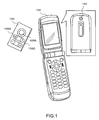
- FIG. 1 is an external view showing a mobile phone as an electronic device and an RC terminal for remote control (a remote control terminal) according to a first embodiment of the present invention.
- a mobile phone 102 shown in the same drawing is a so-called digital camera phone, which includes an image sensor 101.
- a user performs a setting operation to be described later for the mobile phone 102, and thus, by using an arbitrary RC terminal (105), can perform a shutter release operation by the remote control for an image taken by the image sensor 101.
- the RC terminal 105 is not one dedicatedly prepared for the remote control of the mobile phone 102, but is an RC terminal for another purpose.
- the RC terminal 105 may be, for example, an RC terminal for a television set equipped in a hotel where the user is staying in the case of using the mobile phone 102 at the hotel.
- the RC terminal 105 may be an RC terminal for operating a car navigation system equipped in a passenger car in the case of using the mobile phone 102 on the way to a destination to which the user is moving by the passenger car.
- PDAs personal digital assistances
- an RC terminal for such an electronic device may be used as the RC terminal 105.
- an RC terminal dedicated for the video camera may also be used.
- the description described hereinafter takes as an example the case of using, as a button for the shutter release operation of the image sensor 101 built in the mobile phone 102, a button 105A located on an upper center of the RC terminal 105 among plural buttons provided thereon.
- FIG. 2 is a block diagram showing an internal configuration of the mobile phone (in FIG. 1) according to the first embodiment.
- the mobile phone 102 includes a camera unit 201 (including the image sensor 101), an infrared receiving unit 202, a display device 203, a key input device 204, a microcomputer 205, a memory 206, a radio transmitting/receiving circuit 211, a microphone 212, and a speaker 213.
- the camera unit 201 creates digital image data corresponding to a video signal outputted from the image sensor 101.
- the infrared receiving unit 202 receives an infrared signal sent out from an external device (the RC terminal 105 in this embodiment). Moreover, the infrared receiving unit 202 creates information representing a signal pattern of the received infrared signal. This information is sent to the microcomputer 205.
- the display device 203 is a display device including a liquid crystal display unit and the like, and functions as a so-called finder when an operation mode of the mobile phone 102 is a "camera mode".
- the operation mode is simply the "camera mode”
- the mobile phone 102 can record an image taken by the image sensor 101 when a shutter release operation by use of a predetermined operation button is performed in response to the shutter release operation.
- the microcomputer 205 executes, in a central processing unit (CPU) 207, a software program read out from the memory 206, and thus administers an entire operation of the mobile phone 102.
- the microcomputer 205 controls the camera unit 201 in response to the shutter release operation of the user.
- the microcomputer 205 registers the signal pattern of the infrared signal, which is acquired from the external device in a "learning mode (signal registration mode) " that is a first operation mode, as information representing a signal pattern of an infrared signal instructing the shutter release operation.
- the microcomputer 205 allows the infrared receiving unit 202 to receive the infrared signal sent out from the RC terminal 105, in the "camera mode” and a "remote control standby mode", each of which is a second operation mode.
- This infrared signal corresponds to the shutter release operation by the user.
- the microcomputer 205 stores, in the memory 206, the digital image data outputted from the camera unit 201.
- the key input device 204 is an operation key (operation button) used for the user to issue an operation instruction to the mobile phone 102.
- the key input device 204 includes an operation key (not shown) which functions as a shutter in the camera mode.
- the memory 206 is a non-volatile memory (flash memory or the like), and records and stores the information representing the signal pattern of the infrared signal. Furthermore, the memory 206 stores, for example, an operation program of the microcomputer 205 (CPU 207), various kinds of parameters, and user data (for example, mail documents and phone numbers).
- the radio transmitting/receiving circuit 211 performs demodulation of a radio wave received from an antenna and phase modulation for a digital signal outputted from the microcomputer 205. Moreover, the radio transmitting/receiving circuit 211 has a function similar to that of a radio transmitting/receiving circuit of a publicly known wireless communication terminal.
- voice of the user is inputted to the microphone 212.
- the speaker 213 outputs voice (acoustic sound) to the user.
- ones generally used at present may be employed for the following:
- FIG. 3 is a block diagram explaining the software program executed by the microcomputer in the mobile phone according to the first embodiment.
- the respective functions shown in the same drawing are conceptually shown operation functions to be realized by the microcomputer 205 (CPU 207).
- a state switch function 11 is a function to switch the operation mode of the mobile phone 102 to the "learning mode”, the "remote control standby mode", or other operation modes (for example, a standby mode for a phone call and electronic mail).
- the "learning mode” is an operation mode for associating an operation (shutter release operation in this embodiment) of the mobile phone 102, which is desired to be executed by the remote control, with any operation key (button 105A of the RC terminal 105 in this embodiment) of the RC terminal desired by the user.
- the "remote control standby mode” is an operation mode of awaiting an input of the infrared signal from the outside to the infrared receiving unit 202 in order to realize the remote control in an operation mode ("camera mode” in this embodiment) other than the "learning mode".
- a learning function 12 is executed when the operation mode of the mobile phone 102 is the "learningmode (signal registration mode)".
- the learning function 12 is a function for learning (analyzing) the signal pattern of the infrared signal received from the RC terminal (RC terminal 105 shown in FIG. 1 in this embodiment) desired by the user.
- the infrared signal is one outputted from the RC terminal 105 as the user presses the button 105A.
- the learning function 12 is a function for registering, in the memory 206, the information representing the signal pattern as information corresponding to a predetermined operation instruction (shutter release operation in this embodiment) of the mobile phone 102.
- a comparison function 13 is executed when the operation mode of the mobile phone 102 is the "remote control standby mode".
- the comparison function 13 is a function for comparing the information representing the signal pattern registered in the memory 206 by the learning function 12 with the signal pattern (information representing the signal pattern) of the infrared signal received in the infrared receiving unit 202 in response to the operation of the button 105A in the RC terminal 105.
- an operation execution function 14 is executed when the operation mode of the mobile phone 102 is the "remote control standby mode".
- the operation execution function 14 is a function for executing the instructed predetermined operation (shutter release operation in this embodiment) of the mobile phone 102 when a comparison result by the comparison function 13 shows coincidence.
- FIG. 4 is a flowchart showing control processing (learning function 12) in the learning mode of the mobile phone according to the first embodiment. This flowchart shows a processing procedure of the software program executed by the CPU 207 in the microcomputer 205 shown in FIG. 1.
- the user performs a predetermined operation in the key input device 204, and thus instructs the mobile phone 102 to execute (condition) the "learning mode".
- the CPU 207 executes the state switch function 11, and thus shifts the operation mode of the mobile phone 102 to the "learning mode”.
- the CPU 207 starts the control processing (in FIG. 4) for associating the instruction on the predetermined operation (shutter release operation in this embodiment) of the mobile phone 102 with the button (button 105A of the RC terminal 105 in this embodiment) of the RC terminal desired by the user.
- the CPU 207 activates the infrared receiving unit 202 in order to receive an infrared signal (sample signal) to be used for the learning from the outside (Step S1).
- the infrared signal (sample signal) received in Step S1 is one for the learning.
- Such an infrared signal has the same signal pattern as that of an infrared signal received in the "remote control standby mode" to be described later.
- the user confirms that the operation mode of the mobile phone 102 has shifted to the "learning mode".
- the confirmation of the operation mode may be realized, for example, by display of a symbol on the display device 203, and output of a confirmation sound.
- the user who has confirmed that the mobile phone 102 is under operation in the "learning mode” directs the RC terminal 105 toward the image sensor 101, and operates the button 105A in this state.
- the infrared receiving unit 202 receives the infrared signal outputted from the RC terminal 105. Moreover, the infrared receiving unit 202 analyzes the signal pattern of the infrared signal received in Step S1, and thus creates information representing the signal pattern of the infrared signal (Step S2).
- the CPU 207 registers the information representing the signal pattern in the memory 206 in association with the information concerned with the information instructing the predetermined operation (shutter release operation of a digital camera function in this embodiment) in the mobile phone 102 (Step S3).
- the button 105A of the RC terminal 105 and the shutter release operation of the mobile phone 102 have been able to be associated with each other. Accordingly, in order to actually perform the shutter release operation by the remote control, the user performs the predetermined operation in the key input device 204, and thus instructs the mobile phone 102 to execute the "remote control standby mode" and the “camera mode". In this case, the state switch function 11 shifts the operation mode of the mobile phone 102 to the "remote control standby mode” and the "camera mode". In response to this shift, the CPU 207 starts control processing (in FIG. 5) for performing the instructedpredeterminedoperation (shutter release operation in this embodiment) of the mobile phone 102 by the remote control in the RC terminal (RC terminal 105) desired by the user.
- FIG. 5 is a flowchart showing control processing (the comparison function 13 and the operation execution function 14) in the remote control standby mode of the mobile phone according to the first embodiment.
- the CPU 207 activates the infrared receiving unit 202 in order to receive the infrared signal for the remote control from the outside (Step S11).
- the infrared receiving unit 202 receives the infrared signal outputted from the RC terminal 105. Moreover, the infrared receiving unit 202 analyzes the signal pattern of the infrared signal received in Step S11, and thus creates the information representing the signal pattern of the infrared signal (Step S12).
- the CPU 207 compares the information representing the signal pattern, which is created in Step S12, with the information representing the signal pattern registered in the memory 206 (Step S13).
- Step S13 When a result of the comparison in Step S13 shows coincidence (YES in Step S14), the infrared signal received in Step S11 can be determined to be one instructing the shutter release operation by the operation of the button 105A of the RC terminal 105. Accordingly, when the result of the comparison in Step S13 shows the coincidence, the CPU 207 instructs the camera unit 201 on the shutter release operation (Step S15). In this case, the image taken by the image sensor 101 is displayed on the display device 203. The camera unit 201 stores image data corresponding to the taken image in the memory 206 in response to the instruction from the CPU 207 in Step S15.
- Step S13 when the result of the comparison in Step S13 does not show the coincidence (NO in Step S14), the infrared signal received in Step S11 can be determined not to be one of the RC terminal registered normally. Accordingly, the CPU 207 returns the processing to Step S11.
- the mobile phone 102 it is possible for the mobile phone 102 to learn the infrared signal transmitted by the RC terminal.
- the mobile phone 102 can be easily and reliably subjected to the remote control by an RC terminal of the other electronic device or for the other purpose.
- this embodiment it is not necessary to attach the dedicated RC terminal to a product or to prepare the dedicated RC terminal as an optional part in realizing the remote control of the mobile phone 102. Hence, according to this embodiment, total cost of the mobile phone 102 can be reduced with no specification reduction. Hence, this embodiment is suitable in that salability of the mobile phone 102 can be enhanced.
- the RC terminal present close to the user can be easily and reliably registered as one for the remote control of the mobile phone 102, and thus this embodiment is excellent in usability.
- This embodiment is also described specifically with reference to the mobile phone 102 (in FIG. 1) having the built-in image sensor 101.
- the RC terminal 105 is not one dedicatedly prepared for the mobile phone 102, but for example, is the RC terminal for the video camera included in the personal effects of the user.
- buttons of the RC terminal 105 not only the button 105A located on the upper center thereof but also a button 105B for "W (wide-angle) " and a button 105C for "T (telephoto, telescopic)", which are located immediately under the button 105A, are used.
- the camera unit 201 of the mobile phone 102 is capable of a telescopic (T) operation and a wide-angle (W) operation.
- this embodiment is described taking as an example the case of realizing a correspondence to be described below, for convenience' sake of description.
- the button 105B for the wide-angle which is included in the RC terminal 105 for the video camera, is associated with the wide-angle operation of the mobile phone 102 (camera unit 201).
- the button 105C for the telescopic operation which is included in the RC terminal 105, is associated with the telescopic operation of the mobile phone 102 (camera unit 201). Owing to such association, in this embodiment, while an angle of view by the image sensor 101 of the mobile phone 102 is widened in response to an operation of the button 105B, the angle of view is narrowed in response to an operation of the button 105C.
- the user performs a predetermined operation in the key input device 204, and thus instructs the mobile phone 102 to execute the "learning mode".
- the state switch function 11 shifts the operation mode of the mobile phone 102 to the "learning mode”.
- the CPU 207 executes the control processing (learning function 12 in FIG. 4) in the learning mode.
- desired button operations are performed for the buttons 105A to 105C.
- the plural operations to be registered are the shutter release operation, the wide-angle operation, and the telescopic operation.
- Step S1 of the learning mode (in FIG. 4), which has been described in the first embodiment, may be set, for example, as the following processing.
- Step S1 of the learning mode the CPU 207 displays the plural registrable operations (functions) as alternatives on the display device 203.
- the user selects a desired operation from the displayed alternatives by a selection operation using the key input device 204.
- the CPU 207 displays operation guidance on the display device 203.
- this operation guidance includes guidance information, for example, such as: "Operation (function) to be registered was selected in this mobile phone. It is need to operate a desired button of a desired RC terminal so as to associate the selected operation with the desired button. Please, operate the desired button while directing the desired RC terminal toward this mobile phone".
- Step S1 above the CPU 207 executes the processing of Step S2 and Step S3 in a similar way to the first embodiment.
- the plural operations are registered in the memory 206, and accordingly, it is necessary to allocate different regions in the memory 206 for each registration operation.
- the RC terminal 105 sends out infrared signals of signal patterns different for each button. Therefore, the user repeats the registration operation in the "learning mode" according to this embodiment described above, and thus information is registered for each of the buttons in the memory 206 of the mobile phone 102. Specifically, in the memory 206, the information representing the signal patterns different for each of the buttons will be registered in a state of being associated individually with the corresponding operations. According to the above-mentioned specific example, information representing a signal pattern by the button 105A and the shutter release operation of the mobile phone 102 are registered in association with each other. Information representing a signal pattern by the button 105B and the wide-angle operation of the mobile phone 102 are registered in association with each other. Moreover, information representing a signal pattern by the button 105C and the telescopic operation of the mobile phone 102 are registered in association with each other.
- the user's operation for selecting any from the plural operations for a certain signal pattern is not limited to the processing performed in Step S1 (in FIG. 4).
- the processing may be arranged such that the user's operation is performed prior to the registration of the operation in the memory 206 in Step S3 (in FIG. 4).
- a man-machine interface provided by the mobile phone 102 upon the above-mentioned user's operation is not limited to the display device 203 and the key input device 204.
- the processing may be arranged such that an operation (function) which the user desires to select is selected by operating an operation key originally for an operation of the mobile phone 102.
- the buttons 105A to 105C of the RC terminal 105 and the shutter release operation, telescopic operation, and wide-angle operation of the mobile phone 102 have been able to be associated with each other, respectively. Accordingly, in order to actually perform the remote control of the camera unit 201, the user performs a predetermined operation in the key input device 204, and thus instructs the mobile phone 102 to execute the "remote control standby mode" and the “camera mode". In this case, the state switch function 11 shifts the operation mode of the mobile phone 102 to the "remote control standby mode” and the "camera mode". In response to such switch of the operation modes, the CPU 207 starts the control processing (in FIG. 5) for the remote control also in this embodiment. However, in this embodiment, there are plural operations to be executed. Therefore, this embodiment is different from the first embodiment in that there are plural signal patterns to be compared with the signal pattern of the received infrared signal in Step S13.
- infrared communication has been performed between the RC terminal 105 and the infrared receiving unit 202 (mobile phone 102), as an example of communication means for the remote control.
- a communication mode between the RC terminal and the mobile phone 102 is not limited to use of an infrared ray, and various communication modes using an electric wave, visible light, and the like can be employed.
- the high sensitivity image sensor 101 can be used as a sensing mechanism of the infrared signal which is the sample signal.
- the mobile phone 102 it is necessary for the mobile phone 102 to appropriately filter (remove), by internal image processing, the infrared signal received together with the visible light in the image sensor 101 in response to the shutter release operation of the user in an actual image taking operation after the "learning mode (registration)".
- a time difference is set between timing of sensing processing of the infrared signal by the shutter release operation and timing of starting creation processing (image recording operation) of a picture image in response to the shutter release operation, and thus the internal configuration of the mobile phone 102 may be simplified.
- the image sensor 101 originally provided in the mobile phone 102 can be used for the input of the infrared signal (sample signal) in the "learning mode" without providing a new sensing mechanism.
- addition of hardware greatly affects a size of the mobile phone.
- this modification example can be applied not only to the case of using the RC terminal for the infrared communication but also to the case of using an RC terminal in which visible light communication is employed.
- this case it is conceivable that there are many usage modes, where visible light pattern signals for the remote control are included in an angle of view desired by the user when the user who has selected the desired angle of view performs the shutter release operation. Accordingly, in the case of using the RC terminal employing the visible light communication, it is necessary to perform processing for appropriately subjecting the visible light pattern signal for the remote control, which is received by the image sensor 101 of the mobile phone 102, to color conversion by the internal image processing.
- a time difference is set between timing of sensing processing of the visible light pattern signal by the shutter release operation and timing of starting creation processing (image recording operation) of a picture image in response to the shutter release operation, and thus the internal configuration of the mobile phone 102 may be simplified.
- the above-mentioned respective embodiments have been described taking as an example the case of the mobile phone 102 which is an example of the electronic devices.
- the present invention is not limited to the mobile phone, and for example, can be applied to the electronic devices such as the digital camera and the video camera.
- the present invention is not exclusively limited to the electronic devices excellent in portability, such as the mobile phone and the digital cameras, and can also be applied to stationary electronic devices.
- a computer program capable of realizing the functions in the flowcharts (in FIGS. 4 and 5) referred to in the description of the mobile phone 102 is supplied to the mobile phone 102. Thereafter, the computer program is read out to the CPU 207 of the device concerned and executed. Moreover, the computer program supplied into the device concerned may be stored in a readable/writable storage device such as the memory 206.
- procedures generally used at present can be employed, such as a method of installing the computer program in the device concerned by using an appropriate jig and a method of downloading the computer program from the outside through a communication line such as the Internet at a manufacturing stage before the shipment, a maintenance stage after the shipment, or the like.
- the present invention is composed of codes of such a computer program or a storage medium therefor.
- the remote control of the electronic device as the remote control target can be easily and reliably realized without using the remote control terminal (RC terminal) dedicated for the electronic device concerned.
Landscapes
- Engineering & Computer Science (AREA)
- Signal Processing (AREA)
- Computer Networks & Wireless Communication (AREA)
- Multimedia (AREA)
- Computer Hardware Design (AREA)
- Microelectronics & Electronic Packaging (AREA)
- Selective Calling Equipment (AREA)
- Telephonic Communication Services (AREA)
- Telephone Function (AREA)
Abstract
Description
- method of receiving the infrared signal in the
infrared receiving unit 202; - pattern (pattern format) of the received signal;
- recording method of the information representing the
signal pattern in the
memory 206; and the like.
Claims (11)
- A remote control method for an electronic device (102), characterized by comprising:conditioning (11) the electronic device in a first operation mode;registering (12, S1 to S3) a signal pattern of a signal received from a remote control terminal (105) desired by a user in association with a predetermined operation of the electronic device when the electronic device conditions in the first operation mode;operating (11) the electronic device in a second operation mode different from the first operation mode; andexecuting (13, 14, S11 to S15) the predetermined operation in a case where a signal pattern of a signal received from the remote control terminal when the electronic device operates in the second operation mode and the signal pattern registered by the registration coincide with each other.
- The remote control method for an electronic device according to claim 1, characterized in that:the electronic device is a mobile phone having a camera function; andthe signal received by the remote control terminal is sensed by an image sensor (101) for the camera function upon the registering.
- The remote control method for an electronic device according to claim 2, characterized in that, as the predetermined operation, an image sensed by the image sensor is stored in a storage medium upon the executing of the predetermined operation.
- The remote control method for an electronic device according to any one of claims 1 to 3, characterized in that:the remote control terminal includes plural operation buttons (105A to 105C) in which signal patterns to be sent out are mutually different; andthe signal pattern different for each of the operation buttons, which has been received by the remote control terminal, is registered individually in association with any operation of plural operations of the electronic device upon the registering.
- An electronic device (102) capable of accepting an operation instruction by remote control, characterized by comprising:signal registration means (12, 101, 206, 207) for registering a signal pattern of a signal received from an outside in a first operation mode in association with a predetermined operation of the electronic device; andoperation control means (13, 14, 207) for executing the predetermined operation in a case where a signal pattern of a signal received from the outside in a second operation mode different from the first operation mode and the signal pattern registered by said signal registration means coincide with each other.
- The electronic device according to claim 5, characterized in that said signal registration means includes sensing means (201, 202) for sensing the signal received from the outside.
- The electronic device according to claim 6, characterized in that:said electronic device is a mobile phone (102) having a camera function; andsaid sensing means is an image sensor (101) for the camera function.
- The electronic device according to claim 7, characterized in that said operation control means stores an image sensed by the image sensor in a storage medium as the predetermined operation.
- The electronic device according to any one of claims 5 to 8, characterized in that said signal registration means registers each signal pattern of the signal received from the outside in association with any of different operations of said electronic device.
- The electronic device according to any one of claims 5 to 9, characterized in that:the signal received from the outside is an infrared signal, andsaid electronic device further comprising infrared receiving means for receiving the infrared signal.
- A computer program for operation control of an electronic device (102) capable of accepting an operation instruction by remote control, the computer program characterized by causing a computer to implement:a signal registration function (12) to register a signal pattern of a signal received from an outside in a first operation mode in association with a predetermined operation of the electronic device; andan operation control function (13, 14) to execute the predetermined operation in a case where a signal pattern of a signal received from the outside in a second operation mode different from the first operation mode and the signal pattern registered by the signal registration function coincide with each other.
Applications Claiming Priority (2)
| Application Number | Priority Date | Filing Date | Title |
|---|---|---|---|
| JP2003382036A JP2005150878A (en) | 2003-11-12 | 2003-11-12 | Portable information processing apparatus, information processing method |
| JP2003382036 | 2003-11-12 |
Publications (2)
| Publication Number | Publication Date |
|---|---|
| EP1531547A2 true EP1531547A2 (en) | 2005-05-18 |
| EP1531547A3 EP1531547A3 (en) | 2005-10-19 |
Family
ID=34431440
Family Applications (1)
| Application Number | Title | Priority Date | Filing Date |
|---|---|---|---|
| EP04026203A Withdrawn EP1531547A3 (en) | 2003-11-12 | 2004-11-04 | Electronic device, remote control method therefor, and computer program for the electronic device |
Country Status (4)
| Country | Link |
|---|---|
| US (1) | US20050099220A1 (en) |
| EP (1) | EP1531547A3 (en) |
| JP (1) | JP2005150878A (en) |
| CN (1) | CN1617628A (en) |
Families Citing this family (7)
| Publication number | Priority date | Publication date | Assignee | Title |
|---|---|---|---|---|
| US7634263B2 (en) | 2006-01-30 | 2009-12-15 | Apple Inc. | Remote control of electronic devices |
| US8798474B2 (en) * | 2008-03-10 | 2014-08-05 | Koninklijke Philips N.V. | Method and apparatus for communication in an illumination system using a liquid lens |
| US8299954B2 (en) | 2009-12-15 | 2012-10-30 | At&T Intellectual Property I, L.P. | Proxy remote control |
| KR101132951B1 (en) | 2010-10-06 | 2012-04-09 | 어보브반도체 주식회사 | Universal receiver and pattern recognition method thereof |
| US8971556B2 (en) * | 2012-06-10 | 2015-03-03 | Apple Inc. | Remotely controlling a hearing device |
| TWI488016B (en) * | 2012-11-16 | 2015-06-11 | 唐明中 | A portable remote interactive system |
| US10115185B2 (en) | 2014-12-05 | 2018-10-30 | At&T Intellectual Property I, L.P. | Dynamic image recognition model updates |
Family Cites Families (13)
| Publication number | Priority date | Publication date | Assignee | Title |
|---|---|---|---|---|
| JPH0728448B2 (en) * | 1986-02-07 | 1995-03-29 | アールシーエー トムソン ライセンシング コーポレイシヨン | Reconfigurable remote control transmitter |
| JPH0616601B2 (en) * | 1988-09-07 | 1994-03-02 | 三洋電機株式会社 | Power save circuit of received radio wave processing circuit and power save method thereof |
| JP2821174B2 (en) * | 1989-04-21 | 1998-11-05 | オリンパス光学工業株式会社 | Camera remote control device |
| JPH077771A (en) * | 1993-03-19 | 1995-01-10 | Sony Corp | Remote commander |
| US5386251A (en) * | 1993-06-03 | 1995-01-31 | Zilog, Inc. | Television receiver with learning remote control system capable of being controlled by a remote control device manufactured by different companies |
| US6298121B1 (en) * | 1994-06-24 | 2001-10-02 | Intel Corporation | Method and apparatus for making a voice and/or data call over a single analog phone line using a multi-modal DCE |
| US5500691A (en) * | 1995-01-04 | 1996-03-19 | Sony Corporation | Remote control identifier setup in a video system having both IR and RF transmitters |
| JPH09303019A (en) * | 1996-05-20 | 1997-11-25 | Sony Corp | Identification signal registration method and identification signal registration device |
| JP3798476B2 (en) * | 1996-08-30 | 2006-07-19 | 株式会社東芝 | Computer system and cache memory power-down control method in the system |
| AUPP702198A0 (en) * | 1998-11-09 | 1998-12-03 | Silverbrook Research Pty Ltd | Image creation method and apparatus (ART79) |
| US7006802B2 (en) * | 1998-11-09 | 2006-02-28 | Tsui Philip Y W | Universal transmitter |
| US6879806B2 (en) * | 2001-06-01 | 2005-04-12 | Zensys A/S | System and a method for building routing tables and for routing signals in an automation system |
| KR100871218B1 (en) * | 2002-03-21 | 2008-12-01 | 삼성전자주식회사 | Data transmission / reception device between main device and remote device of base station in mobile communication system |
-
2003
- 2003-11-12 JP JP2003382036A patent/JP2005150878A/en active Pending
-
2004
- 2004-10-27 US US10/973,908 patent/US20050099220A1/en not_active Abandoned
- 2004-11-04 EP EP04026203A patent/EP1531547A3/en not_active Withdrawn
- 2004-11-10 CN CN200410090902.5A patent/CN1617628A/en active Pending
Also Published As
| Publication number | Publication date |
|---|---|
| EP1531547A3 (en) | 2005-10-19 |
| US20050099220A1 (en) | 2005-05-12 |
| CN1617628A (en) | 2005-05-18 |
| JP2005150878A (en) | 2005-06-09 |
Similar Documents
| Publication | Publication Date | Title |
|---|---|---|
| CN1642177B (en) | Recording audio and video in a mobile communication terminal | |
| CN100474938C (en) | Remote control device | |
| US20070080845A1 (en) | Universal remote control device with touch screen | |
| US20110037694A1 (en) | Image processing apparatus and method | |
| JP2006146803A (en) | Operation device, and remote operation system | |
| EP1780630A2 (en) | Method and apparatus for displaying key information in portable terminal | |
| US20070174780A1 (en) | Control method for digital image processing apparatus for convenient movement mode and digital image processing apparatus using the method | |
| US20150138393A1 (en) | Electronic device, control method therefor and recording medium | |
| JP2002123349A (en) | Electronic appliance explanation display device and electronic appliance explanation display method | |
| EP1403833A1 (en) | Remote control system | |
| US20150116508A1 (en) | Information processing apparatus, imaging apparatus, imaging system, method of controlling information processing apparatus, method of controlling imaging apparatus, and program | |
| EP1531547A2 (en) | Electronic device, remote control method therefor, and computer program for the electronic device | |
| CN1578351B (en) | Mobile terminal and cursol position notification method | |
| KR101557354B1 (en) | Portable electronic device and method for controlling operational mode thereof | |
| JP4290828B2 (en) | Interface device | |
| CN101308438A (en) | Multifunctional device, function switching method thereof and related electronic device | |
| EP1723580B1 (en) | Image pickup apparatus, electronic tag reading apparatus, and program | |
| JP2009111878A (en) | Portable device and imaging device | |
| JP2008097151A (en) | Information processing apparatus, information processing system, information processing method, and program | |
| JP3993027B2 (en) | Digital camera and photographing system | |
| JP2000206482A (en) | Projection type liquid crystal display | |
| KR200352488Y1 (en) | Personal communication device with camera having a function of remote control | |
| JP2006128854A (en) | Portable terminal device and remote control program for portable terminal device | |
| JP4392161B2 (en) | Data processing system, data processing apparatus, and control method therefor | |
| JP4159270B2 (en) | Digital camera |
Legal Events
| Date | Code | Title | Description |
|---|---|---|---|
| PUAI | Public reference made under article 153(3) epc to a published international application that has entered the european phase |
Free format text: ORIGINAL CODE: 0009012 |
|
| AK | Designated contracting states |
Kind code of ref document: A2 Designated state(s): AT BE BG CH CY CZ DE DK EE ES FI FR GB GR HU IE IS IT LI LU MC NL PL PT RO SE SI SK TR |
|
| AX | Request for extension of the european patent |
Extension state: AL HR LT LV MK YU |
|
| PUAL | Search report despatched |
Free format text: ORIGINAL CODE: 0009013 |
|
| AK | Designated contracting states |
Kind code of ref document: A3 Designated state(s): AT BE BG CH CY CZ DE DK EE ES FI FR GB GR HU IE IS IT LI LU MC NL PL PT RO SE SI SK TR |
|
| AX | Request for extension of the european patent |
Extension state: AL HR LT LV MK YU |
|
| RIC1 | Information provided on ipc code assigned before grant |
Ipc: 7G 08C 19/00 B Ipc: 7G 08C 19/28 B Ipc: 7H 04N 1/21 B Ipc: 7H 04B 1/20 B Ipc: 7H 03J 1/00 A |
|
| 17P | Request for examination filed |
Effective date: 20050909 |
|
| AKX | Designation fees paid |
Designated state(s): DE FR GB IT |
|
| 17Q | First examination report despatched |
Effective date: 20060829 |
|
| STAA | Information on the status of an ep patent application or granted ep patent |
Free format text: STATUS: THE APPLICATION IS DEEMED TO BE WITHDRAWN |
|
| 18D | Application deemed to be withdrawn |
Effective date: 20070109 |