EP1531461A1 - Hologram system - Google Patents
Hologram system Download PDFInfo
- Publication number
- EP1531461A1 EP1531461A1 EP03730502A EP03730502A EP1531461A1 EP 1531461 A1 EP1531461 A1 EP 1531461A1 EP 03730502 A EP03730502 A EP 03730502A EP 03730502 A EP03730502 A EP 03730502A EP 1531461 A1 EP1531461 A1 EP 1531461A1
- Authority
- EP
- European Patent Office
- Prior art keywords
- data
- recording medium
- sector
- recording
- reproduced
- Prior art date
- Legal status (The legal status is an assumption and is not a legal conclusion. Google has not performed a legal analysis and makes no representation as to the accuracy of the status listed.)
- Withdrawn
Links
Images


Classifications
-
- G—PHYSICS
- G06—COMPUTING OR CALCULATING; COUNTING
- G06K—GRAPHICAL DATA READING; PRESENTATION OF DATA; RECORD CARRIERS; HANDLING RECORD CARRIERS
- G06K7/00—Methods or arrangements for sensing record carriers, e.g. for reading patterns
- G06K7/10—Methods or arrangements for sensing record carriers, e.g. for reading patterns by electromagnetic radiation, e.g. optical sensing; by corpuscular radiation
- G06K7/10544—Methods or arrangements for sensing record carriers, e.g. for reading patterns by electromagnetic radiation, e.g. optical sensing; by corpuscular radiation by scanning of the records by radiation in the optical part of the electromagnetic spectrum
- G06K7/10554—Moving beam scanning
- G06K7/10594—Beam path
- G06K7/10603—Basic scanning using moving elements
- G06K7/10663—Basic scanning using moving elements using hologram
-
- G—PHYSICS
- G11—INFORMATION STORAGE
- G11B—INFORMATION STORAGE BASED ON RELATIVE MOVEMENT BETWEEN RECORD CARRIER AND TRANSDUCER
- G11B7/00—Recording or reproducing by optical means, e.g. recording using a thermal beam of optical radiation by modifying optical properties or the physical structure, reproducing using an optical beam at lower power by sensing optical properties; Record carriers therefor
- G11B7/004—Recording, reproducing or erasing methods; Read, write or erase circuits therefor
- G11B7/0065—Recording, reproducing or erasing by using optical interference patterns, e.g. holograms
Definitions
- the present invention relates to a holographic recording medium and a recording and reproduction system utilizing the same.
- a holographic memory system is known as a digital recording system applying the principle of holography.
- the holographic memory system is for recording and reproducing light and shade dot pattern data in a recording medium of a photorefractive crystal such as lithium niobate, for example.
- data can be recorded and reproduced in units of two-dimensional plane pages and multiple recording can be performed using plural pages.
- recording medium as a kind of Fourier transform holograms, recording is performed in units of two-dimensional image pages while being dispersed within three-dimensional space of the recording medium.
- an encoder 25 converts digital data to be recorded in a recording medium 1 on a plane as a light and shade dot pattern image, and rearranges it in a data array of lengthwise 480 bits ⁇ widthwise 640 bits, for example, to produce unit page series data.
- This data is sent out to a spatial light modulator (SLM) 12 such as a panel of a transmissive TFT (Thin Film Transistor) liquid crystal display (hereinafter, also referred to as "LCD").
- SLM spatial light modulator
- LCD Thin Film Transistor
- the spatial light modulator 12 has a modulation processing unit of lengthwise 480 bits ⁇ widthwise 640 bits corresponding to one unit page.
- the spatial light modulator optically modulates an applied signal light beam to a spatial on/off signal of light in response to the unit page series data from the encoder 25, and guides the modulated signal light to a lens 13. More specifically, the spatial light modulator 12 allows the signal light beam to pass through in response to the logical value "1" of the unit page series data as an electrical signal and cuts off the signal light beam in response to the logical value "0". And thereby, electro-optic conversion according to the contents of the respective bits in the unit page data is achieved and the modulated signal light beam as unit page series signal light is produced.
- the signal light enters the recording medium 1 via the lens 13.
- reference light enters at an angle ⁇ (hereinafter, referred to as "incident angle ⁇ ") with a predetermined reference line perpendicular to the optical axis of the beam of the signal light.
- Interference occurs between the signal light and the reference light within the recording medium 1 and the interference fringes are stored as a refractive index grating within the recording medium 1, and thereby, recording of data is performed. Further, plural pieces of two-dimensional plane data is subjected to angle multiple recording by allowing the reference light to enter while changing the incident angle ⁇ , and thereby, a large amount of information can be recorded.
- the recorded data is reproduced from the recording medium 1
- only the reference light is entered into the refractive index grating of the recording medium 1 at the same incident angle ⁇ as that at the time of recording. That is, unlike at the time of recording, the signal light is not allowed to enter.
- the diffracted light from the refractive index grating recorded within the recording medium 1 is guided through a lens 21 to a photodetector 22 such as a CCD (Charge Coupled Device).
- the photodetector 22 converts the light and shade of the incident light into strength of the electrical signal and outputs an analog electrical signal having a level in response to the intensity of the incident light to a decoder 26.
- the decoder 26 compares the analog signal with a predetermined amplitude value (slice level) and reproduces corresponding data of "1" and "0".
- Optical strain, signal image displacement, and the like that occurs from the spatial light modulator to the photodetector by a recording medium when the recording medium is newly loaded must be allowed to fall within a predetermined range of specified values. Further, when a recording medium recorded by a certain recording and reproduction system is reproduced by another recording and reproduction system, the reproduced image is displaced largely due to, for example, variations of the positions from the recording medium to the CCD image pickup device at the times of recording and reproduction. Therefore, the CCD or the recording medium is required to be adjusted precisely according thereto. A defect that there is a problem in compatibility is taken for example.
- a hologram system of the invention has a supporting part for loadably supporting a recording medium made of a photosensitive material such as photorefractive polymer, a hole burning material, or a photochromic material, a signal light generating part for allowing a coherent beam modulated in response to predetermined data to enter the recording medium and providing a three-dimensional light interference pattern therewithin to produce a refractive index grating, and a data processing part for detecting reproduced data by diffracted light from the refractive index grating and demodulating the data to the predetermined data, and the hologram system is characterized in that the recording medium has a reference refractive index grating corresponding to a three-dimensional light interference pattern of a coherent light beam modulated in response to reference data in a reference data area in advance, and the reproduced data is corrected in response to the reference data reproduced from the reference refractive index grating of the reference data area and reference data provided within a reference memory, and demodulated to the predetermined data.
- the reproduced data is corrected based on the reference data held in a hologram recording and reproducing apparatus and a recording medium, respectively, and the original data is demodulated.
- the case where the recorded original data and the reproduced data are different to each other is a case where there is a difference between both of the data due to variations of recording information caused by the difference in recording formats such as the difference in amounts of page data, the individual difference between devices, recording error such as performance error of a recording medium, the individual difference between reproduction optical systems, and reproduction error such as changes due to disturbance.
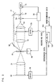
- Figs. 2 and 3 show an example of a recording medium according to the invention and a hologram system including a hologram recording and reproducing apparatus using the medium.
- a card type recording medium 10 made of a photorefractive polymer is shown.
- the card type recording medium 10 there are provided with a reference data area 301, a sector data area 302 and a user data area 303 in parallel.
- reference data 311, for example, R2 is recorded in the recording medium in advance before shipment.
- sector data area 302 respective pieces of sector data 312 are recorded in advance.
- user data 313 is recorded.
- reference data is defined with respect to each recording format.
- These formats are like that there are differences between floppy disks of 1DD, 2DD, and 2HD, for example.
- Various pieces of reference data 311 with respect to other recording media are defined and recorded in the reference data area 301 of the recording medium before shipment.
- respective pieces of reference data 102 are also recorded within a reference memory 101 of a data processing unit 103 in advance.
- the recording medium 10 When the recording medium 10 is loaded in a supporting part 19 of the hologram recording and reproducing apparatus, the reference data 311 of the reference data area 301 that has been recorded in advance before shipment is reproduced. And then, the discrimination of the kind of the recording medium 10 is performed, and then, the apparatus moves to each operation.
- the user data 313 is recorded and, at the same time, the reference data 312 (for example, R2) defined in its recording medium format is recorded in the sector data area 302 determined so as to correspond to the sector of the recording medium 10 in which the user data is recorded.
- the reference data 312 for example, R2
- the reference data 312 (here, R2) defined in the recording medium format recorded in the sector data area 302 is reproduced by either of hologram recording and reproducing apparatuses (by itself or another apparatus).
- the difference between the reproduced reference data and the reference data within the memory of the hologram recording and reproducing apparatus is the sum E1 of the recording error of the hologram recording and reproducing apparatus that has performed recording in the recording medium and the reproduction error of itself.
- the predetermined data can be recreated correctly.
- other sector information such as data indices, amounts of data, data formats, for example, can be recorded as the sector data.
- the light beam output from a laser 15 is split by a beam splitter 16 into two of a light beam for signal that linearly advances and a light beam for reference that is deflected upwardly, and the beams are guided to optical paths of signal and reference light beam optical systems, respectively.
- the light beam for signal that has passed through the beam splitter 16 enters the recording medium 10 through a shutter 6a, a light beam expander 14, the spatial light modulator 12, and the Fourier transform lens 13.
- the time for applying the signal light beam to the recording medium is controlled by an automatic shutter controlled by a controller, and the light beam is expanded into collimated light having a predetermined diameter by the beam expander 14.
- the spatial light modulator 12 is a two-dimensional flat LCD of lengthwise 480 ⁇ widthwise 640 pixels, for example, and converts the light beam from the beam expander 14 into signal light in response to the digital recording data supplied from the encoder 25.
- the light is spatially modulated in response to the recording page data by the spatial light modulator 12 so as to be transmitted or not transmitted with respect to each pixel according to a two-dimensional dot pattern such as a checkered pattern, for example, and then, Fourier transformed by the Fourier transform lens 13, condensed onto the recording medium 10, and thereby, is formed as a point image within the Fourier plane.
- the recording medium 10 is disposed so that the Fourier plane by the lens 13 may be in parallel with the surface of the recording medium 10.
- the reference light beam optical system the reference light beam is reflected by mirrors 17 and 18, entered into the recording medium 10, and allowed to intersect and interfere with the signal light beam from the lens 13 in a position within the recording medium to form three-dimensional interference fringes.
- the optical system of the mirror 18, the lens 13, etc. may be disposed so that the reference light and the signal light may interfere with each other, not on the Fourier plane, but before or behind the Fourier plane.
- the signal light and the reference light are simultaneously applied onto a predetermined region within the recording medium 10, and the interference pattern is recorded as a refractive index grating with the refractive indices changed.
- the time for forming a hologram is controlled by the automatic shutter of a laser light source device.
- the supporting part 19 that places the recording medium 10 in parallel with the plane perpendicular to the signal light optical axis, for example, is driven by a drive unit (not shown).
- the drive unit is controlled by a controller 20.
- the controller 20 drives the supporting part 19 to move and adjust the position of the recording medium 10 in response to the signal corresponding to the positioning data from the photodetector 22.
- the recorded recording medium 10 is disposed on the supporting part 19 as well as at the time of recording, and closing of the shutter 6a and the automatic shutter control of the laser light source device are performed by the control of the controller 20 to allow the reference light from the mirror 18 only to enter.
- the diffracted light from the interference fringes recorded within the recording medium 10 enters the photodetector 22 through an inverse Fourier transform lens 21 as reproduction light, and forms the reproduced image.
- the photodetector 22 has a two-dimensional flat light receiving surface of lengthwise 480 ⁇ widthwise 640 pixels same as that of the spatial light modulator 12, for example, converts the received reproduction light into an electrical signal, and outputs it to the decoder 26.
- the decoder 26 compares the input electrical signal with a predetermined slice level and outputs binary digital data.
- the card type recording medium 10 is used, however, the same recording and reproduction system can be realized using a recording medium having a disk shape or the like.
Landscapes
- Physics & Mathematics (AREA)
- Electromagnetism (AREA)
- Engineering & Computer Science (AREA)
- Health & Medical Sciences (AREA)
- General Health & Medical Sciences (AREA)
- Toxicology (AREA)
- Artificial Intelligence (AREA)
- Computer Vision & Pattern Recognition (AREA)
- General Physics & Mathematics (AREA)
- Theoretical Computer Science (AREA)
- Holo Graphy (AREA)
- Optical Recording Or Reproduction (AREA)
Abstract
A compatible hologram system has a supporting part for
loadably supporting a recording medium made of a photosensitive
material, a signal generating part for allowing a coherent beam
modulated in response to predetermined data to enter the
recording medium and providing a three-dimensional light
interference pattern therewithin to produce a diffraction
grating, and a data processing part for detecting reproduced data
by diffracted light from the diffraction grating and demodulating
the data to the predetermined data. The recording medium has
a reference data area in which a reference diffraction grating
corresponding to a three-dimensional light interference pattern
of a coherent light beam modulated in response to reference data
has been stored in advance, a sector data area in which sector
data is recorded, and a user data area in which user data is
recorded. The hologram system corrects the reproduced data in
response to the reference data reproduced from the reference
diffraction grating stored in the reference data area, the sector
data reproduced from the sector area, and reference data provided
within a reference memory of the data processing part, and
demodulates the data to the predetermined data.
Description
The present invention relates to a holographic recording
medium and a recording and reproduction system utilizing the
same.
Conventionally, as a digital recording system applying the
principle of holography, a holographic memory system is known.
The holographic memory system is for recording and reproducing
light and shade dot pattern data in a recording medium of a
photorefractive crystal such as lithium niobate, for example.
In the holographic memory system, data can be recorded and
reproduced in units of two-dimensional plane pages and multiple
recording can be performed using plural pages. In a recording
medium as a kind of Fourier transform holograms, recording is
performed in units of two-dimensional image pages while being
dispersed within three-dimensional space of the recording medium.
As below, an overview of a recording and reproduction system will
be described.
In Fig. 1, an encoder 25 converts digital data to be recorded
in a recording medium 1 on a plane as a light and shade dot pattern
image, and rearranges it in a data array of lengthwise 480 bits
× widthwise 640 bits, for example, to produce unit page series
data. This data is sent out to a spatial light modulator (SLM)
12 such as a panel of a transmissive TFT (Thin Film Transistor)
liquid crystal display (hereinafter, also referred to as "LCD").
The spatial light modulator 12 has a modulation processing
unit of lengthwise 480 bits × widthwise 640 bits corresponding
to one unit page. The spatial light modulator optically
modulates an applied signal light beam to a spatial on/off signal
of light in response to the unit page series data from the encoder
25, and guides the modulated signal light to a lens 13. More
specifically, the spatial light modulator 12 allows the signal
light beam to pass through in response to the logical value "1"
of the unit page series data as an electrical signal and cuts
off the signal light beam in response to the logical value "0".
And thereby, electro-optic conversion according to the contents
of the respective bits in the unit page data is achieved and the
modulated signal light beam as unit page series signal light is
produced.
The signal light enters the recording medium 1 via the lens
13. In to the recording medium 1, other than the signal light,
reference light enters at an angle β (hereinafter, referred to
as "incident angle β") with a predetermined reference line
perpendicular to the optical axis of the beam of the signal light.
Interference occurs between the signal light and the
reference light within the recording medium 1 and the
interference fringes are stored as a refractive index grating
within the recording medium 1, and thereby, recording of data
is performed. Further, plural pieces of two-dimensional plane
data is subjected to angle multiple recording by allowing the
reference light to enter while changing the incident angle β,
and thereby, a large amount of information can be recorded.
When the recorded data is reproduced from the recording
medium 1, only the reference light is entered into the refractive
index grating of the recording medium 1 at the same incident angle
β as that at the time of recording. That is, unlike at the time
of recording, the signal light is not allowed to enter. Thereby,
the diffracted light from the refractive index grating recorded
within the recording medium 1 is guided through a lens 21 to a
photodetector 22 such as a CCD (Charge Coupled Device). The
photodetector 22 converts the light and shade of the incident
light into strength of the electrical signal and outputs an analog
electrical signal having a level in response to the intensity
of the incident light to a decoder 26. The decoder 26 compares
the analog signal with a predetermined amplitude value (slice
level) and reproduces corresponding data of "1" and "0".
Optical strain, signal image displacement, and the like
that occurs from the spatial light modulator to the photodetector
by a recording medium when the recording medium is newly loaded
must be allowed to fall within a predetermined range of specified
values. Further, when a recording medium recorded by a certain
recording and reproduction system is reproduced by another
recording and reproduction system, the reproduced image is
displaced largely due to, for example, variations of the
positions from the recording medium to the CCD image pickup device
at the times of recording and reproduction. Therefore, the CCD
or the recording medium is required to be adjusted precisely
according thereto. A defect that there is a problem in
compatibility is taken for example.
Accordingly, as a problem of the invention to be solved,
to provide a compatible hologram system is taken for example.
A hologram system of the invention has a supporting part
for loadably supporting a recording medium made of a
photosensitive material such as photorefractive polymer, a hole
burning material, or a photochromic material, a signal light
generating part for allowing a coherent beam modulated in
response to predetermined data to enter the recording medium and
providing a three-dimensional light interference pattern
therewithin to produce a refractive index grating, and a data
processing part for detecting reproduced data by diffracted light
from the refractive index grating and demodulating the data to
the predetermined data, and the hologram system is characterized
in that
the recording medium has a reference refractive index grating corresponding to a three-dimensional light interference pattern of a coherent light beam modulated in response to reference data in a reference data area in advance, and
the reproduced data is corrected in response to the reference data reproduced from the reference refractive index grating of the reference data area and reference data provided within a reference memory, and demodulated to the predetermined data.
the recording medium has a reference refractive index grating corresponding to a three-dimensional light interference pattern of a coherent light beam modulated in response to reference data in a reference data area in advance, and
the reproduced data is corrected in response to the reference data reproduced from the reference refractive index grating of the reference data area and reference data provided within a reference memory, and demodulated to the predetermined data.
Hereinafter, an embodiment of the invention will be
described by referring to the drawings.
In a hologram system of the embodiment, when the recorded
original data and the reproduced data are different to each other,
the reproduced data is corrected based on the reference data held
in a hologram recording and reproducing apparatus and a recording
medium, respectively, and the original data is demodulated. The
case where the recorded original data and the reproduced data
are different to each other is a case where there is a difference
between both of the data due to variations of recording
information caused by the difference in recording formats such
as the difference in amounts of page data, the individual
difference between devices, recording error such as performance
error of a recording medium, the individual difference between
reproduction optical systems, and reproduction error such as
changes due to disturbance.
Figs. 2 and 3 show an example of a recording medium according
to the invention and a hologram system including a hologram
recording and reproducing apparatus using the medium.
In Fig. 3, a card type recording medium 10 made of a
photorefractive polymer is shown. In the card type recording
medium 10, there are provided with a reference data area 301,
a sector data area 302 and a user data area 303 in parallel. In
the reference data area 301, reference data 311, for example,
R2 is recorded in the recording medium in advance before shipment.
In the sector data area 302, respective pieces of sector data
312 are recorded in advance. In the user data area 303, user data
313 is recorded.
In the hologram system of the embodiment, reference data
is defined with respect to each recording format. The reference
data is recorded as recording format data with respect to each
recording format in such a manner that R1 is defined for a low
density recording medium having information of one page within
the recording medium of 256 × 256 = 65536 bits, R2 for a middle
density recording medium of 512 × 512 = 252144 bits, R3 for a
high density recording medium of 1024 × 1024 = 104856 bits. These
formats are like that there are differences between floppy disks
of 1DD, 2DD, and 2HD, for example. Various pieces of reference
data 311 with respect to other recording media are defined and
recorded in the reference data area 301 of the recording medium
before shipment.
Similarly, in the hologram recording and reproducing
apparatus shown in Fig. 2, respective pieces of reference data
102 are also recorded within a reference memory 101 of a data
processing unit 103 in advance.
When the recording medium 10 is loaded in a supporting part
19 of the hologram recording and reproducing apparatus, the
reference data 311 of the reference data area 301 that has been
recorded in advance before shipment is reproduced. And then,
the discrimination of the kind of the recording medium 10 is
performed, and then, the apparatus moves to each operation.
At the time of data recording, the user data 313 is recorded
and, at the same time, the reference data 312 (for example, R2)
defined in its recording medium format is recorded in the sector
data area 302 determined so as to correspond to the sector of
the recording medium 10 in which the user data is recorded.
At the time of data reproduction, the reference data 312
(here, R2) defined in the recording medium format recorded in
the sector data area 302 is reproduced by either of hologram
recording and reproducing apparatuses (by itself or another
apparatus). The difference between the reproduced reference
data and the reference data within the memory of the hologram
recording and reproducing apparatus is the sum E1 of the recording
error of the hologram recording and reproducing apparatus that
has performed recording in the recording medium and the
reproduction error of itself.
By performing demodulation on the reproduction of the data
recorded in the recording medium while taking the difference E1
into consideration, even when the reproduced data is different
from the predetermined data, the predetermined data can be
recreated correctly. In the sector data area 302, other sector
information such as data indices, amounts of data, data formats,
for example, can be recorded as the sector data.
At the time of recording, the light beam output from a laser
15 is split by a beam splitter 16 into two of a light beam for
signal that linearly advances and a light beam for reference that
is deflected upwardly, and the beams are guided to optical paths
of signal and reference light beam optical systems, respectively.
The light beam for signal that has passed through the beam
splitter 16 enters the recording medium 10 through a shutter 6a,
a light beam expander 14, the spatial light modulator 12, and
the Fourier transform lens 13. The time for applying the signal
light beam to the recording medium is controlled by an automatic
shutter controlled by a controller, and the light beam is expanded
into collimated light having a predetermined diameter by the beam
expander 14. The spatial light modulator 12 is a two-dimensional
flat LCD of lengthwise 480 × widthwise 640 pixels, for example,
and converts the light beam from the beam expander 14 into signal
light in response to the digital recording data supplied from
the encoder 25. The light is spatially modulated in response
to the recording page data by the spatial light modulator 12 so
as to be transmitted or not transmitted with respect to each pixel
according to a two-dimensional dot pattern such as a checkered
pattern, for example, and then, Fourier transformed by the
Fourier transform lens 13, condensed onto the recording medium
10, and thereby, is formed as a point image within the Fourier
plane. The recording medium 10 is disposed so that the Fourier
plane by the lens 13 may be in parallel with the surface of the
recording medium 10.
On the other hand, in the reference light beam optical
system, the reference light beam is reflected by mirrors 17 and
18, entered into the recording medium 10, and allowed to intersect
and interfere with the signal light beam from the lens 13 in a
position within the recording medium to form three-dimensional
interference fringes. Here, the optical system of the mirror
18, the lens 13, etc. may be disposed so that the reference light
and the signal light may interfere with each other, not on the
Fourier plane, but before or behind the Fourier plane.
Thus, at the time of data recording, the signal light and
the reference light are simultaneously applied onto a
predetermined region within the recording medium 10, and the
interference pattern is recorded as a refractive index grating
with the refractive indices changed. The time for forming a
hologram is controlled by the automatic shutter of a laser light
source device.
The supporting part 19 that places the recording medium
10 in parallel with the plane perpendicular to the signal light
optical axis, for example, is driven by a drive unit (not shown).
The drive unit is controlled by a controller 20. The controller
20 drives the supporting part 19 to move and adjust the position
of the recording medium 10 in response to the signal corresponding
to the positioning data from the photodetector 22.
On the other hand, at the time of reproduction, the recorded
recording medium 10 is disposed on the supporting part 19 as well
as at the time of recording, and closing of the shutter 6a and
the automatic shutter control of the laser light source device
are performed by the control of the controller 20 to allow the
reference light from the mirror 18 only to enter.
The diffracted light from the interference fringes
recorded within the recording medium 10 enters the photodetector
22 through an inverse Fourier transform lens 21 as reproduction
light, and forms the reproduced image. The photodetector 22 has
a two-dimensional flat light receiving surface of lengthwise 480
× widthwise 640 pixels same as that of the spatial light modulator
12, for example, converts the received reproduction light into
an electrical signal, and outputs it to the decoder 26. The
decoder 26 compares the input electrical signal with a
predetermined slice level and outputs binary digital data.
By the way, in the above example, the card type recording
medium 10 is used, however, the same recording and reproduction
system can be realized using a recording medium having a disk
shape or the like.
Claims (5)
- A hologram system having a supporting part for loadably supporting a recording medium made of a photosensitive material, a signal generating part for allowing a coherent beam modulated in response to predetermined data to enter said recording medium and providing a three-dimensional light interference pattern therewithin to produce a diffraction grating, and a data processing part for detecting reproduced data by diffracted light from said diffraction grating and demodulating the data to the predetermined data, the hologram system is characterized in that
said recording medium has a reference data area in which a reference diffraction grating corresponding to a three-dimensional light interference pattern of a coherent light beam modulated in response to reference data has been stored in advance, a sector data area in which sector data is recorded, and a user data area in which user data is recorded, and
said reproduced data is corrected in response to said reference data reproduced from said reference diffraction grating stored in said reference data area, said sector data reproduced from said sector area, and reference data provided within a reference memory of said data processing part, and demodulated to the predetermined data. - A hologram system according to claim 1, wherein said signal light generating part includes a reference light generating part for allowing a coherent reference light beam of a first wavelength as said coherent light beam to enter said recording medium, modulates a coherent signal light beam of the first wavelength as said coherent light beam in response to said data, allows the beam to enter said recording medium and intersect with said coherent reference light beam therewithin to produce a three-dimensional light interference pattern with said reference light.
- A hologram system according to claim 1 or 2, wherein said reference data within said reference memory of said data processing part includes various kinds of recording format data according to various recording media.
- A hologram system according to any one of claims 1 to 3, wherein reference data that said reference diffraction grating stored in said reference data area of said recording medium has includes recording format data of said recording medium.
- A hologram system according to any one of claims 1 to 4, wherein sector data recorded in said sector data area of said recording medium includes at least recording format data of said recording medium.
Applications Claiming Priority (3)
| Application Number | Priority Date | Filing Date | Title |
|---|---|---|---|
| JP2002225054A JP2004069771A (en) | 2002-08-01 | 2002-08-01 | Hologram system |
| JP2002225054 | 2002-08-01 | ||
| PCT/JP2003/006143 WO2004019330A1 (en) | 2002-08-01 | 2003-05-16 | Hologram system |
Publications (1)
| Publication Number | Publication Date |
|---|---|
| EP1531461A1 true EP1531461A1 (en) | 2005-05-18 |
Family
ID=31943810
Family Applications (1)
| Application Number | Title | Priority Date | Filing Date |
|---|---|---|---|
| EP03730502A Withdrawn EP1531461A1 (en) | 2002-08-01 | 2003-05-16 | Hologram system |
Country Status (5)
| Country | Link |
|---|---|
| US (1) | US20060164705A1 (en) |
| EP (1) | EP1531461A1 (en) |
| JP (1) | JP2004069771A (en) |
| AU (1) | AU2003242310A1 (en) |
| WO (1) | WO2004019330A1 (en) |
Families Citing this family (6)
| Publication number | Priority date | Publication date | Assignee | Title |
|---|---|---|---|---|
| JP2006251675A (en) * | 2005-03-14 | 2006-09-21 | Fujitsu Ltd | Optical recording medium reproducing apparatus, recording / reproducing apparatus, and reproducing method |
| JP2006268907A (en) * | 2005-03-22 | 2006-10-05 | Fujitsu Ltd | Hologram recording medium and recording / reproducing apparatus |
| US7898924B2 (en) * | 2006-09-07 | 2011-03-01 | International Business Machines Corporation | Apparatus, system, and method for calibrating a holographic storage device |
| JP6286546B2 (en) * | 2013-07-30 | 2018-02-28 | ドルビー ラボラトリーズ ライセンシング コーポレイション | Projector display system with non-mechanical mirror beam steering |
| US9049413B2 (en) | 2013-07-30 | 2015-06-02 | Dolby Laboratories Licensing Corporation | Multiple stage modulation projector display systems having efficient light utilization |
| CN107533318B (en) * | 2015-04-27 | 2021-06-29 | 索尼公司 | Holographic recording composition, holographic recording medium, and method for producing holographic recording medium |
Family Cites Families (4)
| Publication number | Priority date | Publication date | Assignee | Title |
|---|---|---|---|---|
| JP3758231B2 (en) * | 1995-07-25 | 2006-03-22 | ソニー株式会社 | Signal recording apparatus and method, and signal reproducing apparatus and method |
| JPH1093546A (en) * | 1996-09-19 | 1998-04-10 | Dainippon Printing Co Ltd | Encryption system using information recording medium and recording medium for encrypted information |
| US6081912A (en) * | 1996-12-26 | 2000-06-27 | Lucent Technologies Inc. | Method for modulating data for storage in page-wise memory |
| US6064586A (en) * | 1998-12-31 | 2000-05-16 | Siros Technologies, Inc. | Method for holographic data storage and retrieval |
-
2002
- 2002-08-01 JP JP2002225054A patent/JP2004069771A/en not_active Abandoned
-
2003
- 2003-05-16 AU AU2003242310A patent/AU2003242310A1/en not_active Abandoned
- 2003-05-16 US US10/522,679 patent/US20060164705A1/en not_active Abandoned
- 2003-05-16 EP EP03730502A patent/EP1531461A1/en not_active Withdrawn
- 2003-05-16 WO PCT/JP2003/006143 patent/WO2004019330A1/en not_active Ceased
Non-Patent Citations (1)
| Title |
|---|
| See references of WO2004019330A1 * |
Also Published As
| Publication number | Publication date |
|---|---|
| JP2004069771A (en) | 2004-03-04 |
| AU2003242310A1 (en) | 2004-03-11 |
| US20060164705A1 (en) | 2006-07-27 |
| WO2004019330A1 (en) | 2004-03-04 |
Similar Documents
| Publication | Publication Date | Title |
|---|---|---|
| EP1833048B1 (en) | Hologram recorder and hologram recording method | |
| US6909529B2 (en) | Method and apparatus for phase correlation holographic drive | |
| JP5466833B2 (en) | Method for performing page-based holographic recording and readout | |
| US9715426B2 (en) | Monocular holographic data storage system and method thereof | |
| EP1551011A1 (en) | Information recording method, reproducing method and recording/reproducig method utilizing holography | |
| US7633660B2 (en) | Hologram recording apparatus and method | |
| US7539116B2 (en) | Holographic digital data storage system compatible with holographic and reflective medium | |
| US6320683B1 (en) | Optical information recording and reproducing apparatus using a volume holographic memory | |
| EP1507177A1 (en) | Multiplex recording type hologram recording device, method, hologram reproduction device, and method | |
| JP2006154163A (en) | Hologram recording apparatus, hologram reproducing apparatus, hologram recording method, and hologram reproducing method | |
| KR20080112569A (en) | Holographic recording / playback device with variable aperture size | |
| US7079469B2 (en) | Hologram recording/reproducing system | |
| JP4059977B2 (en) | 3D holographic data storage system | |
| US6301028B1 (en) | Holographic memory and optical information recording and reproducing apparatus using the same | |
| EP1531461A1 (en) | Hologram system | |
| EP1708182A2 (en) | Hologram recorder | |
| EP2126907B1 (en) | Holographic storage system for reading a hologram stored on a holographic storage medium and a method carried out therewith | |
| US7428206B2 (en) | Holographic information recording apparatus | |
| US6181665B1 (en) | Volume holographic data storage system | |
| KR100381406B1 (en) | Holographic digital data storage system compatible with a cd/dvd player | |
| JP4631473B2 (en) | Hologram recording / reproducing apparatus and hologram recording / reproducing method | |
| JP2008123665A (en) | Beam shift element for optical storage system | |
| EP1850336B1 (en) | Optical information reproducing apparatus and optical information recording apparatus using holography | |
| KR20080064357A (en) | Angle Multiplexing Method of Holographic Information Recording / Playback Device | |
| US20100118682A1 (en) | Apparatus and method for recording data on holographic storage medium |
Legal Events
| Date | Code | Title | Description |
|---|---|---|---|
| PUAI | Public reference made under article 153(3) epc to a published international application that has entered the european phase |
Free format text: ORIGINAL CODE: 0009012 |
|
| 17P | Request for examination filed |
Effective date: 20050201 |
|
| AK | Designated contracting states |
Kind code of ref document: A1 Designated state(s): AT BE BG CH CY CZ DE DK EE ES FI FR GB GR HU IE IT LI LU MC NL PT RO SE SI SK TR |
|
| AX | Request for extension of the european patent |
Extension state: AL LT LV MK |
|
| DAX | Request for extension of the european patent (deleted) | ||
| RBV | Designated contracting states (corrected) |
Designated state(s): DE FR GB |
|
| STAA | Information on the status of an ep patent application or granted ep patent |
Free format text: STATUS: THE APPLICATION HAS BEEN WITHDRAWN |
|
| 18W | Application withdrawn |
Effective date: 20070702 |